EP1832680A2 - Switch machine with switch point connectors - Google Patents
Switch machine with switch point connectors Download PDFInfo
- Publication number
- EP1832680A2 EP1832680A2 EP07108998A EP07108998A EP1832680A2 EP 1832680 A2 EP1832680 A2 EP 1832680A2 EP 07108998 A EP07108998 A EP 07108998A EP 07108998 A EP07108998 A EP 07108998A EP 1832680 A2 EP1832680 A2 EP 1832680A2
- Authority
- EP
- European Patent Office
- Prior art keywords
- switch
- collar
- bore
- operating rod
- operating
- Prior art date
- Legal status (The legal status is an assumption and is not a legal conclusion. Google has not performed a legal analysis and makes no representation as to the accuracy of the status listed.)
- Granted
Links
- 230000033001 locomotion Effects 0.000 claims description 24
- 230000007246 mechanism Effects 0.000 claims description 14
- 230000008859 change Effects 0.000 claims description 4
- 230000000087 stabilizing effect Effects 0.000 description 11
- 238000006073 displacement reaction Methods 0.000 description 5
- 230000001788 irregular Effects 0.000 description 5
- 230000009471 action Effects 0.000 description 3
- 230000008901 benefit Effects 0.000 description 2
- 239000000356 contaminant Substances 0.000 description 2
- 230000004048 modification Effects 0.000 description 2
- 238000012986 modification Methods 0.000 description 2
- 230000002028 premature Effects 0.000 description 2
- XLYOFNOQVPJJNP-UHFFFAOYSA-N water Substances O XLYOFNOQVPJJNP-UHFFFAOYSA-N 0.000 description 2
- 230000006866 deterioration Effects 0.000 description 1
- 230000000694 effects Effects 0.000 description 1
- 230000005484 gravity Effects 0.000 description 1
- 230000004044 response Effects 0.000 description 1
- 230000000717 retained effect Effects 0.000 description 1
- 230000011664 signaling Effects 0.000 description 1
Images



Classifications
-
- B—PERFORMING OPERATIONS; TRANSPORTING
- B61—RAILWAYS
- B61L—GUIDING RAILWAY TRAFFIC; ENSURING THE SAFETY OF RAILWAY TRAFFIC
- B61L5/00—Local operating mechanisms for points or track-mounted scotch-blocks; Visible or audible signals; Local operating mechanisms for visible or audible signals
Definitions
- the present invention is in the field of railroad switching devices, namely the equipment which is used to displace railroad switch points. More specifically, the invention refers to a pivoting connector which connects each of the operating rods of the switching device to the associated switch point, in a non-binding relationship.
- a railroad switch point consists of tapered rail sections which are capable of being selectively displaced between two different lateral positions at a rail switch and then locked in the selected position, in order to facilitate the desired routing of a train passing through the switch.
- the two switch points are typically displaced by rods extending from an assembly which is referred to herein as a "switch machine". Inside the switch machine the rods are usually connected to a motive mechanism which provides reciprocating rectilinear motion, controlled by a power unit which is usually placed to one side of the rails.
- the switch machine combines the switch point movement and switch point locking functions into a single mechanism to reduce mechanical complexity, enclosing the mechanism in a weather-proof housing, incorporating sensors and other electrical control components in the housing and locating the housing and operating assembly beneath the switch points and the associated rails.
- binding may occur, as described below, when the operating rod does not move along its intended longitudinal line of action, but rather is subjected to lateral forces tending to cause it to bind at its attachment to the switch point and where the operating rod passes through the switch machine housing.
- a bearing and a seal are usually provided at the entry point into the housing, to align the operating rod and to seal out water and other contaminants.
- the outer end of each operating rod connects to an associated switch point, and as the operating rod is moved into and out of the switch machine housing, this substantially longitudinal movement of the operating rod is used to apply force to move the associated switch point laterally.
- the lateral movement of the switch point requires some change in the angle between the operating rod and the switch point, because the switch point is actually pivoting about a pivot point at the other end of the switch point rail section. So, this change in angle can apply a lateral reactive force on the outer end of the operating rod, causing the inner end of the operating rod to apply substantial lateral force to the bearing and seal mechanism through which the operating rod enters the switch machine housing. This lateral reactive force can cause premature failure of the seal and binding of the operating rod relative to the housing, which can cause the switch machine to lock up.
- the present invention is illustrated as implemented with a switch machine for operating a switch having switch points.
- Two operating rods extend from either side of a fixed housing positioned between intersecting rails, to the movable switch points, with the rods being capable of longitudinally sliding relative to the housing. Movement of the operating rods moves the switch points between two positions between the pair of rails.
- the switch machine operates to hold the rods in place to selectively lock the operating rods and the switch points in a desired position.
- a pivoting connector assembly is provided on the outer end of each operating rod.
- a socket mounted or formed on the outer end of the operating rod has a vertically oriented bore into which a pivot shaft is positioned, with a collar at the top of the vertical pivot shaft.
- a horizontal bore is formed in the collar, and the collar bore is adapted to pivot about the vertical axis of the pivot shaft.
- a horizontal pivot pin is attached essentially parallel to each switch point. This pivot pin is positioned through the collar bore, in a sliding arrangement.
- the collar slides along the horizontal pivot pin by a slight amount.
- the collar pivots about the vertical axis to maintain the alignment of the collar bore axis with the horizontal axis of the pivot pin. This prevents the pivot pin from imposing a lateral reactive force on the operating rod.
- Figures 11 and 12 show sectional views of a collar on the connector along line 11-11 of Figure 10.
- the switch machine includes three basic types of fixed components: a fixed housing 1; a plate 2 fixedly mounted within or otherwise attached to the housing 1; and two guides 3 fixedly mounted within or otherwise attached to the housing 1, below the level of the fixed upper plate 2.
- a capture mechanism including a plurality of capture elements and a shifting body, is used to selectively engage and disengage two operating rods 4, 5 to and from the fixed upper plate 2. More specifically, an upper set of interlocking or capture elements are provided to selectively interlock or engage the two operating rods 4, 5 with either the fixed upper plate 2 or the shifting body within the housing 1.
- the fixed upper plate 2 is provided with two ball seats 24 mounted on the upper side thereof.
- Each of the ball seats 24 houses a corresponding disk or follower plate 21 which can be completely inserted in its respective ball seat 24 against the action of a spring 22.
- a lower set of interlocking elements are also provided to selectively interlock the shifting body with either the two fixed lower guides 3 or a control rod 8.
- each of the two fixed lower guides 3 is provided with two transverse pin seats 32, with each pin seat 32 having sloping walls.
- the movable components include the two operating rods 4, 5 which slidingly contact the lower side of the fixed plate 2, and which move the two switch points A1, A2 transversely.
- the switch points A1, A2 are connected by one or more transverse bars 9, so that the switch points A1, A2 always move together and maintain their transverse spacing.
- the switch points A1, A2 can move so that they contact either of two stock rails C1, C2 for the purpose of directing a passing rail car along the desired track.
- Each operating rod 4, 5 is provided with a through hole 41, 51 sized to allow a ball 42 to pass therethrough, with each ball 42 being sized to pass into one of the ball seats 24.
- the thickness of each operating rod 4, 5 in the vicinity of its respective through hole 41, 51 is at least half the diameter of the ball 42.
- a pin of suitable configuration could be used instead of the ball 42, and it could pass through corresponding shaped slots instead of the through holes 41, 51.
- the shifting body within the housing 1 includes a skate 6 and an intermediate shift assembly 7.
- the skate 6, which slidingly contacts the lower sides of the operating rods 4, 5 is provided with two ball slots 61, 62 recessed into its upper surface, oriented transverse to the longitudinal axis of the skate 6.
- the wall of each ball slot 61, 62 closest to the center of the skate 6 slopes upwardly toward the center.
- Each ball slot 61, 62 is able to accept one of the balls 42, with the depth of the ball slot 61, 62 being no more than half the diameter of the ball 42.
- On the lower side of the skate 6 a semi-cylindrical lower central cavity 63 is provided, with the axis of the semi-cylindrical cavity 63 being parallel to the longitudinal axis of the skate 6.
- Two transversely oriented stabilizing recesses 65 are provided in the lower side of the skate 6, one stabilizing recess 65 being positioned beyond each end of the central cavity 63.
- Each stabilizing recess 65 is capable of housing one transversely oriented, cylindrical, end stroke stabilizing pin 66.
- the intermediate shift assembly 7 is positioned in contact with the lower side of the skate 6, with the longitudinal axis of the shift assembly 7 parallel to the longitudinal axis of the skate 6.
- the shift assembly 7 includes a hollow central cylinder 71, provided with a cylindrical sleeve 72 fixedly surrounding each end of the central cylinder 71.
- Each sleeve 72 has two symmetrical wings 73 extending radially therefrom, transverse to the longitudinal axis of the shift assembly 7.
- the upper portion of the central cylinder 71 and the cylindrical sleeves 72 of the shift assembly 7 can be securely inserted into the central cavity 63 on the lower side of the skate 6.
- the symmetrical wings 73 rest flat on the upper sides of the fixed guides 3, with the lower portions of the central cylinder 71 and the cylindrical sleeves 72 positioned between the fixed guides 3.
- Through slots 74 are provided in each of the wings 73, through which transversely oriented, cylindrical, shift pins 75 can pass in order to seat in the pin seats 32 in the upper sides of the fixed guides 3.
- the control rod 8 controlled by an external power unit not shown in the drawings, enters the housing 1 from one side.
- the control rod 8 can slide through the whole shift assembly 7, and it is provided with U-shaped right and left shift forks 81,_83 straddling the outer ends of the sleeves 72.
- the shift forks 81, 83 are fixedly mounted on, or integral with, the control rod 8, and they can partially slide over the tops of the wings 73 of the shift assembly 7.
- On the upper surface of each of the forks 81, 83 an approximately semi-cylindrical transverse groove 82 is provided, to receive the stabilizing pins 66 which are housed in the stabilizing recesses 65 in the lower side of the skate 6.
- An external power unit (not shown) can be provided outside the rails, and mounted to one side of the housing 1, with a drive shaft, as is known in the art, passing under the rails and connected to the control rod 8 for achieving bi-directional longitudinal movement of the control rod 8.
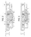
- FIGs 2 to 5 the sequential steps of the normal functioning of the switch machine are illustrated, and the relative positions of the switch machine components are shown.
- the right switch point A2 is in contact with the right stock rail C2 at the full right end position of the stroke, and the control rod 8 is stabilized relative to the skate 6 by the left end stroke stabilizing pin 66 which is seated in the groove 82 on top of the left fork 83 and partially housed in the left stabilizing recess 65 in the lower side of the skate 6.
- the right operating rod 5 is captured relative to the fixed plate 2 by the right ball 42, which is partially housed by the right through hole 51 in the rod 5 and partially housed in the right ball seat 24 of the plate 2.
- the left operating rod 4 is also held in place relative to the fixed plate 2. Therefore, in the configuration shown in Figure 2, the switch points A1, A2 are held in place at the right end of the stroke.
- the shift assembly 7 is captured or latched relative to the fixed guides 3 by the left shift pins 75, which are partially housed in the through slots 74 in the left wings 73, partially housed in the left pin seats 32 of the fixed guides 3, and held in place by the left fork 83 extending over the through slots 74.
- This latching prevents any movement of the shift assembly 7, such as might be caused by vibration, in order to lock the switch machine in this position.
- each left shift pin 75 is cleared by the displacement of the left fork 83 toward the left. It is at this point that the shift assembly 7 and the skate 6 are unlatched, and they can begin to move to the left relative to the fixed guide 3, in response to the force exerted by the right fork 81. Because of the extended length of the left ball slot 61, the control rod 8, the skate 6, and the shift assembly 7 can all move to the left relative to the left operating rod 4, even though the right ball 42 is still capturing the right operating rod 5 in place.
- the left shift pins 75 are pushed up the sloping left walls of the left pin seats 32 by the right walls of the through slots 74 in the left wings 73, until the shift assembly 7 is completely disengaged from the fixed guides 3.
- the assembly made of the operating rods 4, 5, the transverse bar 9, and the switch points A1, A2, is also then captured relative to the fixed plate 2 by the left ball 42.
- the right shift pins 75 have aligned with, and dropped into, the right pin seats 32 in the fixed guides 3.
- the right ball 42 has completed its displacement along the right ball slot 62, and it now abuts the right wall of the right ball slot 62. This abutment of the right ball 42 with the right wall of the right ball slot 62 has stopped the leftward movement of the skate 6 and the shift assembly 7 relative to the fixed plate 2.
- control rod 8 and the forks 81, 83 have continued to move leftward until the right shift pins 75 are captured within the right pin seats 32 of the fixed guides 3 by the right fork 81, securely latching or capturing the shift assembly 7 and the skate 6 relative to the fixed guides 3. Further, the right end stroke stabilizing pin 66 has dropped partially into the groove 82 on top of the fork 81, stabilizing the control rod 8 relative to the skate 6. This locks and latches the switch machine at the full left end of its stroke.
- the control rod 8 is not affected by possible loads which may be exerted on the detached right switch point A2. Such loads are transmitted to the switch point A1 via the transverse bar 9, and to the operating rod 4, and they are then absorbed by the plate 2, to which the left operating rod 4 is captured. Furthermore, since the right fork 81 captures the right shift pins 75 in the right pin seats 32, this prevents accidental shifting of the switch machine, which could be caused, for example, by vibrations.
- Shifting of the mechanism back to the right is accomplished in a similar fashion to the leftward shifting.
- Electrical sensors incorporated in locations in the mechanism such as the forks 81, 83 act to monitor the correct or incorrect positioning of the mechanism at the right and left end points of its stroke. That is, as can readily be seen from Figure 2, an electrical sensor in the left fork 83 senses attainment of its rightmost position relative to the left operating rod 4, at the right end point of the stroke of the switch machine. Similarly, an electrical sensor in the right fork 81 senses attainment of its leftmost position relative to the right operating rod 5, at the left end point of the stroke of the switch machine.
- These sensors may be any suitable sensor such as shown for example in U. S. Patent No. 6,149,106 and may be engageable with the forks 81, 83 and the operating rods 4, 5. Alternatively, the sensors may be mounted elsewhere within the switch machine so as to sense the position of one element relative to another element within the switch machine.
- an obstacle between the left switch point A1 and the left stock rail C1 can prevent the full displacement of the switch point A1 to abut the left stock rail C1.
- the obstacle causes the switch point A1 to stop advancing, and the displacement of the control rod 8 can not reach the predetermined end-stroke point.
- a sensor in the right fork 81 will readily indicate that the control rod 8 has not reached the end of its stroke relative to the operating rods 4, 5, so that this type of irregular condition is made evident.
- This irregular functioning may then be communicated to associated wayside signalling equipment or remotely to a data center communicating with the switch.
- a second type of irregular functioning can be caused by the absence of the stroke rail C1 in the correct position.
- the displacement of the switch point A1 is not opposed by the stock rail C1; therefore, the left side of the left through hole 41 never offers sufficient resistance to the movement of the left ball 42 to cause the left ball 42 to react against the sloped wall of the left ball slot 61 and move upwardly, compressing the spring 22 and entering the left ball seat 24. Therefore, the skate 6 is not released from its engagement with the left operating rod 4, and the operating rods 4, 5 continue to move to the left with the control rod 8.
- a sensor in the right fork 81 will readily indicate that the control rod 8 has not reached the end of its stroke relative to the operating rods 4, 5, so that this type of irregular condition is made evident. Such event is then communicated to other wayside equipment or a remote data center.
- Figures 6 through 12 illustrate connectors, according to the present invention, for the switch machine.
- Figure 6 shows a side elevation view of a switch machine incorporating this modification, with the switch machine housing 1 itself being shown in section, to show the location of a bearing 102 and a seal 104 on each operating rod 4, 5.
- the bearing 102 aligns the operating rod 4, 5 to move along a line of action on the axis of the internal mechanism of the switch machine, while the seal 104 seals out water and other contaminants which could cause deterioration or even malfunctioning of the switch machine.
- a socket 106 is provided at the outer end of each operating rod 4, 5.
- Each operating rod socket 106 is pivotably connected to its associated switch point A1, A2, by a yoke 112, a pivot pin 108, and a mounting clip 110.
- each switch point A1, A2 along with the respective section of rail to which it is attached pivots around an axis, such as the axis 200 shown in Figure 7A when the switch point is moved.
- the pivot radius of the rail is relatively large compared to the dimensions of the other elements shown in Figure 6, and thus the location of the axis 200 is not shown to scale.
- the angle 140 will change slightly. That is, for example, if the operating rod 5 moves to the right, the angle 140 between the operating rod 5 and the switch point A2 will increase slightly.
- the connectors are also operative with and provide benefit for other between-the-rail switch machines, in which the switch points are not tied together, other than via the operating rods.
- the socket 106, the yoke 112, and the pivot pin 108 have features which allow the switch point A2 to pivot freely relative to the operating rod 5, without imposing a reactive pivoting force on the operating rod 5.
- the same arrangement is provided at the connection between the operating rod 4 and its associated switch point A1.
- the operating rod socket 106 has a vertical bore 118 therethrough, with the bore 118 being centered on a vertical axis 120.
- a clevis pin hole 124 can be provided laterally through the socket 106, and transversely through the socket bore 118, for use with some embodiments, as discussed below.
- the yoke 112 has a vertical shaft 116, which is positionable in the socket bore 118, centered on the vertical axis 120. If not pinned to the socket 106, the yoke 112 can pivot about the vertical axis 120 of the vertical shaft 116, relative to the vertical bore 118 of the socket 106.
- the pivot pin 108 is rigidly mounted to the switch point by means of the mounting clip 110, with the longitudinal axis 122 of the pivot pin 108 being oriented horizontally and substantially parallel to the axis of the switch point.
- the yoke 112 is slidingly attached to the pivot pin 108, by means of a collar 114 at the top of the vertical shaft 116 of the yoke 112. That is, the collar 114 at the top of the yoke 112 has a horizontal bore into which the pivot pin 108 is received, and the collar 114 is free to slide along the pivot pin 108.
- the yoke 112 has a vertical shaft 116, at the top of which is mounted a pivoting collar 114.
- the collar 114 pivots about the vertical axis 120, relative to the vertical shaft 116 via a vertical pivot pin (not shown), or alternatively, it could be fixedly mounted to the vertical shaft 116, in which case the collar 114 pivots with the shaft 116.
- a horizontal bore 126 is provided through the collar 114, with the collar bore 126 being centered on the horizontal axis 122 of the pivot pin 108. It can be seen that, as the collar 114 pivots, the horizontal axis 122 of the collar bore 126 pivots about the vertical axis 120 of the vertical shaft 116.
- the yoke 112 has a vertical shaft 116 and a collar 114, as before.
- the collar 114 has an inner collar member 128 and an outer collar member 132, as shown in Figures 11 and 12.
- the collar bore 126 in this instance passes through the inner collar member 128.
- the inner collar member 128 can be a truncated spherical member as shown, positioned in a spherical cavity 134 within the outer collar member 132. It will be seen that this allows the inner collar member 128 to pivot relative to the outer collar member 132, with the result that the horizontal axis 122 of the collar bore 126 pivots about the vertical axis 120. In fact, pivoting of the collar bore 126 relative to the outer collar member 132 can also have a vertical component as well as a horizontal component. If the plane of the switch point movement is not exactly orthogonal to the vertical axis 120, this vertical component of the pivoting of the collar bore 126 can be important to further prevent binding of the operating rods 4, 5. In this embodiment, as before, the outer collar member 132 may be fixedly attached to the vertical shaft 116, or it may be allowed to pivot relative thereto.
- the yoke 112 is adapted to allow the axis 122 of the collar bore 126 to pivot about the vertical axis 120, in a substantially horizontal plane. This can be accomplished by allowing the vertical shaft 116 to pivot in the socket bore 118, by allowing the collar 114 to pivot relative to the vertical shaft 116, by allowing an inner collar member 128 to pivot relative to an outer collar member 132, or by any combination of these three mechanisms. Where some portion of the collar 114 is adapted to pivot relative to the vertical shaft 116, the vertical shaft 116 can be retained to the operating rod socket 118, by a retainer pin placed in the clevis pin hole 130. Where pivoting is accomplished by allowing the shaft 116 to pivot relative to the socket 106, the clevis pin hole 130 may not be used.
Landscapes
- Engineering & Computer Science (AREA)
- Mechanical Engineering (AREA)
- Railway Tracks (AREA)
- Rotary Switch, Piano Key Switch, And Lever Switch (AREA)
- Mechanical Control Devices (AREA)
- Train Traffic Observation, Control, And Security (AREA)
- Switches With Compound Operations (AREA)
- Switch Cases, Indication, And Locking (AREA)
- Nonwoven Fabrics (AREA)
- Driving Mechanisms And Operating Circuits Of Arc-Extinguishing High-Tension Switches (AREA)
- Seats For Vehicles (AREA)
Abstract
Description
- Not Applicable
- Not Applicable
- Field of the Invention - The present invention is in the field of railroad switching devices, namely the equipment which is used to displace railroad switch points. More specifically, the invention refers to a pivoting connector which connects each of the operating rods of the switching device to the associated switch point, in a non-binding relationship.
- Background Art - A railroad switch point consists of tapered rail sections which are capable of being selectively displaced between two different lateral positions at a rail switch and then locked in the selected position, in order to facilitate the desired routing of a train passing through the switch. The two switch points are typically displaced by rods extending from an assembly which is referred to herein as a "switch machine". Inside the switch machine the rods are usually connected to a motive mechanism which provides reciprocating rectilinear motion, controlled by a power unit which is usually placed to one side of the rails.
- Such a device is described in
Italian Patent No. IT1246656 5,806,809 and6,149,106 . - The switch machine combines the switch point movement and switch point locking functions into a single mechanism to reduce mechanical complexity, enclosing the mechanism in a weather-proof housing, incorporating sensors and other electrical control components in the housing and locating the housing and operating assembly beneath the switch points and the associated rails.
- In such switch machines, binding may occur, as described below, when the operating rod does not move along its intended longitudinal line of action, but rather is subjected to lateral forces tending to cause it to bind at its attachment to the switch point and where the operating rod passes through the switch machine housing. A bearing and a seal are usually provided at the entry point into the housing, to align the operating rod and to seal out water and other contaminants. The outer end of each operating rod connects to an associated switch point, and as the operating rod is moved into and out of the switch machine housing, this substantially longitudinal movement of the operating rod is used to apply force to move the associated switch point laterally. The lateral movement of the switch point requires some change in the angle between the operating rod and the switch point, because the switch point is actually pivoting about a pivot point at the other end of the switch point rail section. So, this change in angle can apply a lateral reactive force on the outer end of the operating rod, causing the inner end of the operating rod to apply substantial lateral force to the bearing and seal mechanism through which the operating rod enters the switch machine housing. This lateral reactive force can cause premature failure of the seal and binding of the operating rod relative to the housing, which can cause the switch machine to lock up.
- It would be desirable to have a means for preventing this application of lateral force to the outer end of the operating rod, in order to eliminate the binding of the operating rod at the housing, and in order to preserve the condition of the housing seal.
- The present invention is illustrated as implemented with a switch machine for operating a switch having switch points. Two operating rods extend from either side of a fixed housing positioned between intersecting rails, to the movable switch points, with the rods being capable of longitudinally sliding relative to the housing. Movement of the operating rods moves the switch points between two positions between the pair of rails. The switch machine operates to hold the rods in place to selectively lock the operating rods and the switch points in a desired position.
- In accordance with the present invention, a pivoting connector assembly is provided on the outer end of each operating rod. In one form of the invention, a socket mounted or formed on the outer end of the operating rod has a vertically oriented bore into which a pivot shaft is positioned, with a collar at the top of the vertical pivot shaft. A horizontal bore is formed in the collar, and the collar bore is adapted to pivot about the vertical axis of the pivot shaft. A horizontal pivot pin is attached essentially parallel to each switch point. This pivot pin is positioned through the collar bore, in a sliding arrangement. As the operating rod moves the switch point laterally, the collar slides along the horizontal pivot pin by a slight amount. Further, as the switch point moves laterally, the collar pivots about the vertical axis to maintain the alignment of the collar bore axis with the horizontal axis of the pivot pin. This prevents the pivot pin from imposing a lateral reactive force on the operating rod.
- The novel features of this invention, as well as the invention itself, will be best understood from the attached drawings, taken along with the following description, in which similar reference characters refer to similar parts, and in which:
-
- Figure 1 is an exploded view of the lower components of a switch machine which can implement the present invention;
- Figure 2 shows the switch mechanism holding the switch points in the full right position in the locked mode;
- Figure 3 shows the switch machine in the full right position of Figure 2, but with the control rod moved to the left to unlock the switch machine to move the switch points;
- Figure 4 shows the switch machine with the control rod moved further to the left to move the switch points from the full right position toward the full left position;
- Figure 5 shows the switch points moved to the full left position;
- Figure 6 shows a switch machine incorporating a modification according to the present invention;
- Figure 7A shows a schematic view of the rail layout of a switch point;
- Figure 7B shows a top plan view of the apparatus in Figure 6;
- Figure 8 shows a perspective view of a pivoting connector according to the present invention;
- Figure 9 shows a first form of the connector according to the present invention;
- Figure 10 shows another form of the connector according to the present invention; and
- Figures 11 and 12 show sectional views of a collar on the connector along line 11-11 of Figure 10.
- As seen in the attached drawings, the switch machine includes three basic types of fixed components: a fixed housing 1; a
plate 2 fixedly mounted within or otherwise attached to the housing 1; and two guides 3 fixedly mounted within or otherwise attached to the housing 1, below the level of the fixedupper plate 2. A capture mechanism, including a plurality of capture elements and a shifting body, is used to selectively engage and disengage twooperating rods upper plate 2. More specifically, an upper set of interlocking or capture elements are provided to selectively interlock or engage the twooperating rods upper plate 2 or the shifting body within the housing 1. As part of the upper set of interlocking elements, the fixedupper plate 2 is provided with twoball seats 24 mounted on the upper side thereof. Each of theball seats 24 houses a corresponding disk orfollower plate 21 which can be completely inserted in itsrespective ball seat 24 against the action of aspring 22. A lower set of interlocking elements are also provided to selectively interlock the shifting body with either the two fixed lower guides 3 or acontrol rod 8. As part of the lower set of interlocking elements, each of the two fixed lower guides 3 is provided with twotransverse pin seats 32, with eachpin seat 32 having sloping walls. - The movable components include the two
operating rods fixed plate 2, and which move the two switch points A1, A2 transversely. The switch points A1, A2 are connected by one or moretransverse bars 9, so that the switch points A1, A2 always move together and maintain their transverse spacing. The switch points A1, A2 can move so that they contact either of two stock rails C1, C2 for the purpose of directing a passing rail car along the desired track. Eachoperating rod hole ball 42 to pass therethrough, with eachball 42 being sized to pass into one of theball seats 24. The thickness of eachoperating rod hole ball 42. One skilled in the art will recognize that a pin of suitable configuration could be used instead of theball 42, and it could pass through corresponding shaped slots instead of the throughholes - The shifting body within the housing 1 includes a
skate 6 and anintermediate shift assembly 7. Theskate 6, which slidingly contacts the lower sides of theoperating rods ball slots skate 6. The wall of eachball slot skate 6 slopes upwardly toward the center. Eachball slot balls 42, with the depth of theball slot ball 42. On the lower side of the skate 6 a semi-cylindrical lowercentral cavity 63 is provided, with the axis of thesemi-cylindrical cavity 63 being parallel to the longitudinal axis of theskate 6. Two transversely oriented stabilizingrecesses 65 are provided in the lower side of theskate 6, one stabilizingrecess 65 being positioned beyond each end of thecentral cavity 63. Each stabilizingrecess 65 is capable of housing one transversely oriented, cylindrical, endstroke stabilizing pin 66. - The
intermediate shift assembly 7 is positioned in contact with the lower side of theskate 6, with the longitudinal axis of theshift assembly 7 parallel to the longitudinal axis of theskate 6. Theshift assembly 7 includes a hollowcentral cylinder 71, provided with acylindrical sleeve 72 fixedly surrounding each end of thecentral cylinder 71. Eachsleeve 72 has twosymmetrical wings 73 extending radially therefrom, transverse to the longitudinal axis of theshift assembly 7. The upper portion of thecentral cylinder 71 and thecylindrical sleeves 72 of theshift assembly 7 can be securely inserted into thecentral cavity 63 on the lower side of theskate 6. Thesymmetrical wings 73 rest flat on the upper sides of the fixed guides 3, with the lower portions of thecentral cylinder 71 and thecylindrical sleeves 72 positioned between the fixed guides 3. Throughslots 74 are provided in each of thewings 73, through which transversely oriented, cylindrical, shift pins 75 can pass in order to seat in the pin seats 32 in the upper sides of the fixed guides 3. - The
control rod 8, controlled by an external power unit not shown in the drawings, enters the housing 1 from one side. Thecontrol rod 8 can slide through thewhole shift assembly 7, and it is provided with U-shaped right and leftshift forks 81,_83 straddling the outer ends of thesleeves 72. Theshift forks control rod 8, and they can partially slide over the tops of thewings 73 of theshift assembly 7. On the upper surface of each of theforks transverse groove 82 is provided, to receive the stabilizingpins 66 which are housed in the stabilizingrecesses 65 in the lower side of theskate 6. - An external power unit (not shown) can be provided outside the rails, and mounted to one side of the housing 1, with a drive shaft, as is known in the art, passing under the rails and connected to the
control rod 8 for achieving bi-directional longitudinal movement of thecontrol rod 8. - In Figures 2 to 5, the sequential steps of the normal functioning of the switch machine are illustrated, and the relative positions of the switch machine components are shown. In Figure 2, the right switch point A2 is in contact with the right stock rail C2 at the full right end position of the stroke, and the
control rod 8 is stabilized relative to theskate 6 by the left endstroke stabilizing pin 66 which is seated in thegroove 82 on top of theleft fork 83 and partially housed in theleft stabilizing recess 65 in the lower side of theskate 6. In this position, theright operating rod 5 is captured relative to the fixedplate 2 by theright ball 42, which is partially housed by the right throughhole 51 in therod 5 and partially housed in theright ball seat 24 of theplate 2. Of course, because of the rigid connection between the switch points A1,_A2 effected by thetransverse bar 9, theleft operating rod 4 is also held in place relative to the fixedplate 2. Therefore, in the configuration shown in Figure 2, the switch points A1, A2 are held in place at the right end of the stroke. Further, in this configuration, theshift assembly 7 is captured or latched relative to the fixed guides 3 by the left shift pins 75, which are partially housed in the throughslots 74 in theleft wings 73, partially housed in the left pin seats 32 of the fixed guides 3, and held in place by theleft fork 83 extending over the throughslots 74. This latching prevents any movement of theshift assembly 7, such as might be caused by vibration, in order to lock the switch machine in this position. - When it is desired to move the switch points A1, A2 from the right end position toward the left end position, movement of the
control rod 8 toward the left part of the drawing, as indicated by the arrow in Figure 2, is caused by the aforementioned power unit. This movement of thecontrol rod 8 first forces the left endstroke stabilizing pin 66 upwardly out of the leftsemi-cylindrical groove 82 into theleft recess 65, allowing thecontrol rod 8 to move leftward. In Figure 3, shortly after this movement toward the left is initiated, it can be seen that the inner edge of theright fork 81 is abutting the right shift pins 75 which in turn exert a force to the left on the left walls of the throughslots 74 in theright wings 73 of theassembly 7. Further, the region over eachleft shift pin 75 is cleared by the displacement of theleft fork 83 toward the left. It is at this point that theshift assembly 7 and theskate 6 are unlatched, and they can begin to move to the left relative to the fixed guide 3, in response to the force exerted by theright fork 81. Because of the extended length of theleft ball slot 61, thecontrol rod 8, theskate 6, and theshift assembly 7 can all move to the left relative to theleft operating rod 4, even though theright ball 42 is still capturing theright operating rod 5 in place. As theshift assembly 7 moves to the left, the left shift pins 75 are pushed up the sloping left walls of theleft pin seats 32 by the right walls of the throughslots 74 in theleft wings 73, until theshift assembly 7 is completely disengaged from the fixed guides 3. - As the
control rod 8 continues to move to the left, theright fork 81 pushes theshift assembly 7 and theskate 6 to the left, with respect to theoperating rods right ball 42 is eventually expelled, by gravity and thespring 22, from theright ball seat 24 into theright ball slot 62 in the upper side of theskate 6. This releases theright operating rod 5 from the fixedplate 2; at the same time, theleft ball 42 runs along the whole length of theleft ball slot 61 on theskate 6. This sequence of movements, all initiated by the movement of thecontrol rod 8 to the left, has the effect of unlocking the operatingrods transverse bar 9, and the switch points A1, A2 for movement to their respective left positions. Continued leftward movement of thecontrol rod 8, theshift assembly 7, and theskate 6 pushes theleft operating rod 4 to the left, because of theleft ball 42 being abutted by the right wall of theleft ball slot 61 and captured in theleft ball slot 61 by the fixedplate 2. This configuration is shown in Figure 4. Leftward movement of the operatingrods transverse bar 9. The switch points A1, A2 are thus moved away from the full right position and toward the left position. - As seen in Figure 5, leftward movement has continued until the left switch point A1 abuts the left stock rail C1, and the
left ball 42 is positioned directly under theleft disk 21 and theleft ball seat 24. This positions the operatingrods - At this left end point of the operating
rods control rod 8 causes theleft ball 42 to be forced upwardly against thedisk 21, because of the slope of the right wall of theleft ball seat 61 and resistance to further movement of theball 42 by the left side of the throughhole 41. As theleft ball 42 is forced upwardly, it compresses thespring 22, until theleft ball 42 enters theleft ball seat 24. Once theleft ball 42 rises at least partially into the left throughhole 41, it creates an interference which prevents the operatingrods plate 2. However, the operatingrod 8, theskate 6, and theshift assembly 7 can continue moving to the left because of the extended length of theright ball slot 62, until the right shift pins 75 engage theshift assembly 7 with the right pin seats 32 in the fixed guides 3. - The assembly made of the operating
rods transverse bar 9, and the switch points A1, A2, is also then captured relative to the fixedplate 2 by theleft ball 42. At this point, the right shift pins 75 have aligned with, and dropped into, the right pin seats 32 in the fixed guides 3. Also, theright ball 42 has completed its displacement along theright ball slot 62, and it now abuts the right wall of theright ball slot 62. This abutment of theright ball 42 with the right wall of theright ball slot 62 has stopped the leftward movement of theskate 6 and theshift assembly 7 relative to the fixedplate 2. However, thecontrol rod 8 and theforks right fork 81, securely latching or capturing theshift assembly 7 and theskate 6 relative to the fixed guides 3. Further, the right endstroke stabilizing pin 66 has dropped partially into thegroove 82 on top of thefork 81, stabilizing thecontrol rod 8 relative to theskate 6. This locks and latches the switch machine at the full left end of its stroke. - It can be seen that, in this locked and latched configuration, the
control rod 8 is not affected by possible loads which may be exerted on the detached right switch point A2. Such loads are transmitted to the switch point A1 via thetransverse bar 9, and to the operatingrod 4, and they are then absorbed by theplate 2, to which theleft operating rod 4 is captured. Furthermore, since theright fork 81 captures the right shift pins 75 in the right pin seats 32, this prevents accidental shifting of the switch machine, which could be caused, for example, by vibrations. - Shifting of the mechanism back to the right is accomplished in a similar fashion to the leftward shifting.
- Electrical sensors incorporated in locations in the mechanism such as the
forks left fork 83 senses attainment of its rightmost position relative to theleft operating rod 4, at the right end point of the stroke of the switch machine. Similarly, an electrical sensor in theright fork 81 senses attainment of its leftmost position relative to theright operating rod 5, at the left end point of the stroke of the switch machine. These sensors may be any suitable sensor such as shown for example in U. S. Patent No.6,149,106 and may be engageable with theforks rods - In a first type of irregular functioning of the switch machine, an obstacle between the left switch point A1 and the left stock rail C1 can prevent the full displacement of the switch point A1 to abut the left stock rail C1. The obstacle causes the switch point A1 to stop advancing, and the displacement of the
control rod 8 can not reach the predetermined end-stroke point. A sensor in theright fork 81 will readily indicate that thecontrol rod 8 has not reached the end of its stroke relative to theoperating rods - A second type of irregular functioning can be caused by the absence of the stroke rail C1 in the correct position. In that case, the displacement of the switch point A1 is not opposed by the stock rail C1; therefore, the left side of the left through
hole 41 never offers sufficient resistance to the movement of theleft ball 42 to cause theleft ball 42 to react against the sloped wall of theleft ball slot 61 and move upwardly, compressing thespring 22 and entering theleft ball seat 24. Therefore, theskate 6 is not released from its engagement with theleft operating rod 4, and the operatingrods control rod 8. As in the previous example, a sensor in theright fork 81, for example, will readily indicate that thecontrol rod 8 has not reached the end of its stroke relative to theoperating rods - Figures 6 through 12 illustrate connectors, according to the present invention, for the switch machine. Figure 6 shows a side elevation view of a switch machine incorporating this modification, with the switch machine housing 1 itself being shown in section, to show the location of a
bearing 102 and aseal 104 on each operatingrod bearing 102 aligns the operatingrod seal 104 seals out water and other contaminants which could cause deterioration or even malfunctioning of the switch machine. Asocket 106 is provided at the outer end of each operatingrod rod socket 106 is pivotably connected to its associated switch point A1, A2, by ayoke 112, apivot pin 108, and a mountingclip 110. - Assume that each switch point A1, A2, along with the respective section of rail to which it is attached pivots around an axis, such as the
axis 200 shown in Figure 7A when the switch point is moved. However, it should be noted that the pivot radius of the rail is relatively large compared to the dimensions of the other elements shown in Figure 6, and thus the location of theaxis 200 is not shown to scale. As shown in Figures 7A and 7B, as the operatingrod angle 140, will change slightly. That is, for example, if the operatingrod 5 moves to the right, theangle 140 between the operatingrod 5 and the switch point A2 will increase slightly. If the operatingrod 5 were locked at a given angle relative to the switch point A2, the lateral reactive force imposed on the operatingrod 5 by the pivoting switch point A2 would cause the operating rod to try to pivot in a counter-clockwise direction, as viewed in Figure 7B. Similarly, if the operatingrod 5 were fixedly attached at a given point on thepin 108, pivoting of the switch point would pull theoperating rod 5 to one side. These types of lateral or pivoting force on the operatingrod 5 would cause it to bind in thebearing 102 and theseal 104. This binding would, at the very least, cause accelerated wear and premature failure of thebearing 102 and theseal 104. Further, this binding could actually lock up the entire switch machine, especially in the case where the two switch points are tied together as discussed hereinabove. - However, the connectors, as described below, are also operative with and provide benefit for other between-the-rail switch machines, in which the switch points are not tied together, other than via the operating rods.
- To prevent this binding, the
socket 106, theyoke 112, and thepivot pin 108 have features which allow the switch point A2 to pivot freely relative to the operatingrod 5, without imposing a reactive pivoting force on the operatingrod 5. The same arrangement is provided at the connection between the operatingrod 4 and its associated switch point A1. As seen better in Figure 8, the operatingrod socket 106 has avertical bore 118 therethrough, with thebore 118 being centered on avertical axis 120. Aclevis pin hole 124 can be provided laterally through thesocket 106, and transversely through the socket bore 118, for use with some embodiments, as discussed below. - The
yoke 112 has avertical shaft 116, which is positionable in the socket bore 118, centered on thevertical axis 120. If not pinned to thesocket 106, theyoke 112 can pivot about thevertical axis 120 of thevertical shaft 116, relative to thevertical bore 118 of thesocket 106. Thepivot pin 108 is rigidly mounted to the switch point by means of the mountingclip 110, with thelongitudinal axis 122 of thepivot pin 108 being oriented horizontally and substantially parallel to the axis of the switch point. Theyoke 112 is slidingly attached to thepivot pin 108, by means of acollar 114 at the top of thevertical shaft 116 of theyoke 112. That is, thecollar 114 at the top of theyoke 112 has a horizontal bore into which thepivot pin 108 is received, and thecollar 114 is free to slide along thepivot pin 108. - As seen in Figure 9, the
yoke 112 has avertical shaft 116, at the top of which is mounted apivoting collar 114. Thecollar 114 pivots about thevertical axis 120, relative to thevertical shaft 116 via a vertical pivot pin (not shown), or alternatively, it could be fixedly mounted to thevertical shaft 116, in which case thecollar 114 pivots with theshaft 116. In all cases, ahorizontal bore 126 is provided through thecollar 114, with the collar bore 126 being centered on thehorizontal axis 122 of thepivot pin 108. It can be seen that, as thecollar 114 pivots, thehorizontal axis 122 of the collar bore 126 pivots about thevertical axis 120 of thevertical shaft 116. - In a further embodiment, seen in Figure 10, the
yoke 112 has avertical shaft 116 and acollar 114, as before. However, in this embodiment, thecollar 114 has aninner collar member 128 and anouter collar member 132, as shown in Figures 11 and 12. The collar bore 126 in this instance passes through theinner collar member 128. - The
inner collar member 128 can be a truncated spherical member as shown, positioned in aspherical cavity 134 within theouter collar member 132. It will be seen that this allows theinner collar member 128 to pivot relative to theouter collar member 132, with the result that thehorizontal axis 122 of the collar bore 126 pivots about thevertical axis 120. In fact, pivoting of the collar bore 126 relative to theouter collar member 132 can also have a vertical component as well as a horizontal component. If the plane of the switch point movement is not exactly orthogonal to thevertical axis 120, this vertical component of the pivoting of the collar bore 126 can be important to further prevent binding of the operatingrods outer collar member 132 may be fixedly attached to thevertical shaft 116, or it may be allowed to pivot relative thereto. - It should be understood that, whichever embodiment of the
yoke 112 is used, theyoke 112 is adapted to allow theaxis 122 of the collar bore 126 to pivot about thevertical axis 120, in a substantially horizontal plane. This can be accomplished by allowing thevertical shaft 116 to pivot in the socket bore 118, by allowing thecollar 114 to pivot relative to thevertical shaft 116, by allowing aninner collar member 128 to pivot relative to anouter collar member 132, or by any combination of these three mechanisms. Where some portion of thecollar 114 is adapted to pivot relative to thevertical shaft 116, thevertical shaft 116 can be retained to theoperating rod socket 118, by a retainer pin placed in theclevis pin hole 130. Where pivoting is accomplished by allowing theshaft 116 to pivot relative to thesocket 106, theclevis pin hole 130 may not be used. - It can be seen, then, that as the operating
rod 5 extends, for instance, to move its associated switch point A2 laterally to the right, thecollar 114 slides along thehorizontal axis 122 of thepivot pin 108, toward the free end of the switch point A2. Simultaneously, the collar bore 126 pivots about thevertical axis 120, relative to theoperating rod socket 106. The combination of this sliding movement and this pivoting movement prevents the imposition of lateral reactive forces on the operating rods tending to bend or pivot the operatingrod 5 relative to thebearing 102 and theseal 104. - While the particular invention as herein shown and disclosed in detail is fully capable of obtaining the objects and providing the advantages hereinbefore stated, it is to be understood that this disclosure is merely illustrative of the presently preferred embodiments of the invention and that no limitations are intended other than as described in the appended claims.
Claims (6)
- A switch machine for operating a railroad switch with two switch points (A1,A2)at intersecting railroad rails, said switch machine comprising:a housing (1) mounted between said two switch points;two operating rods (4,5), each one of said operating rods having an inner end within said housing and an outer end extending from said housing for repositioning one of said switch points, each one of said operating rods and its associated switch point establishing an angle (140) therebetween for the application of lateral force to the switch point to move the switch point;a shifting mechanism (7) within said housing, said shifting mechanism being engageable to said inner end of each one of said operating rods, said shifting mechanism being adapted to simultaneously shift said operating rods between two positions relative to said housing (1), resulting in simultaneous repositioning of said two switch points (A1,A2); anda connector assembly (112) connecting each one of said extending operating rod ends to its associated switch point (A1,A2), said connector assembly having freedom of movement in the horizontal direction extending substantially parallel to the switch point and being pivotable about a vertical axis (120) to allow said angle between said operating rod (4,5) and said associated switch point (A1,A2) to change as said associated switch point is repositioned;whereby said switch machine is adapted to move said switch points (A1,A2) by extending and retracting said operating rods (4,5) by the application of said force acting substantially along the longitudinal axes of said operating rods.
- The switch machine recited in claim 1, wherein each said connector assembly (112) comprises:a horizontal pivot pin (108) mounted on the associated switch point, with its longitudinal axis extending substantially parallel to said switch point;a socket (106) on said operating rod at the outer end thereof, said socket having an open bore with a vertical axis;a vertical shaft (116) in said operating rod socket bore; anda collar (114) on said vertical shaft, said collar having an open bore (126) adapted to receive said pivot pin therethrough in longitudinally sliding engagement, said collar bore being rotatable about said vertical axis of said socket bore.
- The switch machine recited in claim 2, wherein each said vertical shaft (116) is adapted to pivot about its axis, relative to its associated said operating rod socket.
- The switch machine recited in claim 2, wherein:each said vertical shaft (116) is fixedly mounted in its associated said socket bore (118); andeach said collar bore (126) is adapted to pivot relative to its associated said vertical shaft (116).
- The switch machine recited in claim 2, wherein each said collar (114) comprises:an outer collar member fixedly mounted to the associated said vertical shaft; (116) andan inner collar member within said outer collar member, said collar bore (126) being formed in said inner collar member, said inner collar member being rotatable about said vertical axis relative to said outer collar member.
- The switch machine recited in claim 1, wherein each said connector assembly (112) comprises:a horizontal pivot pin (108) mounted on the associated switch point, with its longitudinal axis extending substantially parallel to said switch point; anda collar (114) on a respective said operating rod (4,5), said collar having an open bore (126) adapted to receive said pivot pin therethrough in longitudinally sliding engagement, said collar bore being pivotable about a vertical axis (120).
Applications Claiming Priority (2)
| Application Number | Priority Date | Filing Date | Title |
|---|---|---|---|
| US10/780,116 US20050178929A1 (en) | 2004-02-17 | 2004-02-17 | Switch machine with improved switch point connectors |
| EP05712112A EP1718803B1 (en) | 2004-02-17 | 2005-01-26 | Pivoting connector assembly for a railroad switch |
Related Parent Applications (1)
| Application Number | Title | Priority Date | Filing Date |
|---|---|---|---|
| EP05712112A Division EP1718803B1 (en) | 2004-02-17 | 2005-01-26 | Pivoting connector assembly for a railroad switch |
Publications (3)
| Publication Number | Publication Date |
|---|---|
| EP1832680A2 true EP1832680A2 (en) | 2007-09-12 |
| EP1832680A3 EP1832680A3 (en) | 2007-09-26 |
| EP1832680B1 EP1832680B1 (en) | 2015-12-30 |
Family
ID=34838510
Family Applications (2)
| Application Number | Title | Priority Date | Filing Date |
|---|---|---|---|
| EP05712112A Expired - Lifetime EP1718803B1 (en) | 2004-02-17 | 2005-01-26 | Pivoting connector assembly for a railroad switch |
| EP07108998.1A Ceased EP1832680B1 (en) | 2004-02-17 | 2005-01-26 | Switch machine with switch point connectors |
Family Applications Before (1)
| Application Number | Title | Priority Date | Filing Date |
|---|---|---|---|
| EP05712112A Expired - Lifetime EP1718803B1 (en) | 2004-02-17 | 2005-01-26 | Pivoting connector assembly for a railroad switch |
Country Status (10)
| Country | Link |
|---|---|
| US (1) | US20050178929A1 (en) |
| EP (2) | EP1718803B1 (en) |
| CN (2) | CN102139703A (en) |
| AU (1) | AU2005217383B2 (en) |
| BR (1) | BRPI0506612B1 (en) |
| CA (1) | CA2555727C (en) |
| DE (1) | DE602005003796T2 (en) |
| RU (1) | RU2358057C2 (en) |
| WO (1) | WO2005083177A1 (en) |
| ZA (1) | ZA200607346B (en) |
Families Citing this family (11)
| Publication number | Priority date | Publication date | Assignee | Title |
|---|---|---|---|---|
| DK1960244T3 (en) * | 2005-12-07 | 2011-05-16 | Gen Electric | Lubrication-free track branch system |
| US20080251649A1 (en) * | 2007-04-10 | 2008-10-16 | Justin Salmans | Railway Switching System |
| US8020493B2 (en) * | 2008-12-29 | 2011-09-20 | Universal City Studios Llc | Track-switching device and method |
| US7946538B1 (en) * | 2009-12-09 | 2011-05-24 | Donald Coy Beaman | External point spring locking device |
| DE102012017627B4 (en) * | 2012-09-06 | 2022-08-04 | Schwihag Ag | spring rocker |
| ES2495090A1 (en) * | 2013-03-15 | 2014-09-16 | Talleres Alegría S.A. | Retention device for mobile elements in railway equipment (Machine-translation by Google Translate, not legally binding) |
| JP2016053758A (en) * | 2014-09-02 | 2016-04-14 | 村田機械株式会社 | Travelling vehicle system |
| US9592842B1 (en) * | 2015-09-03 | 2017-03-14 | John Mercer | Railroad locomotive control system having switch position indication and method of use |
| US9932054B2 (en) * | 2016-02-19 | 2018-04-03 | Progress Rail Services Corporation | Double point derail switch |
| CN108263435B (en) * | 2016-12-30 | 2020-11-20 | 比亚迪股份有限公司 | Turnout locking device and rail transit system having the same |
| US10822005B2 (en) * | 2018-03-12 | 2020-11-03 | Twinco Manufacturing Co., Inc. | Submersible switch point machine |
Citations (4)
| Publication number | Priority date | Publication date | Assignee | Title |
|---|---|---|---|---|
| EP0480303A2 (en) | 1990-10-10 | 1992-04-15 | SASIB S.p.A. | Operating device for railway switches, particularly for high-speed lines |
| IT1246656B (en) | 1991-01-10 | 1994-11-24 | Siliani Angiolo Spa | Equipment for operating the tongues of railway points |
| US5806809A (en) | 1997-03-12 | 1998-09-15 | Danner; Don D. | Railroad switch point position sensing system and method |
| US6149106A (en) | 1998-09-03 | 2000-11-21 | Union Switch & Signal Inc. | Railroad switch point position indicator |
Family Cites Families (15)
| Publication number | Priority date | Publication date | Assignee | Title |
|---|---|---|---|---|
| SU46602A1 (en) * | 1935-09-04 | 1936-04-30 | М.С. Кулик | Arrow switch |
| FR828268A (en) * | 1937-10-25 | 1938-05-13 | D Aiguillages Et App De Voie D | Safety device for switching points and crossings |
| FR1279988A (en) * | 1960-11-04 | 1961-12-29 | S N C Grandi Antonio Di Dante | Ball joint for railway installations |
| SE396425B (en) * | 1976-01-19 | 1977-09-19 | Elektromekano Bredaryd | SPARVEXEL |
| IT1213950B (en) * | 1987-12-16 | 1990-01-05 | Sasib Spa | UNIVERSAL EXTERNAL CHANGEOVER DEVICE FOR RAILWAY SWITCHES |
| DE4014248A1 (en) * | 1990-05-04 | 1991-11-07 | Butzbacher Weichenbau Gmbh | DEVICE FOR LOCKING A SWITCH TONGUE WITH A JAW RAIL |
| DE69104431T2 (en) * | 1990-07-19 | 1995-04-20 | Siliani Angiolo Spa | Device for operating the switch tongues of a railway switch. |
| SE506183C2 (en) * | 1993-05-27 | 1997-11-17 | Abb Daimler Benz Transp | Device at railroad tracks for the change of track gear |
| FR2741365B1 (en) * | 1995-11-22 | 1997-12-26 | Gec Alsthom Transport Sa | DEVICE FOR LOCKING A NEEDLE BLADE OF A NEEDLE, DEVICE FOR OPERATING AND LOCKING A NEEDLE BLADE, METHOD OF INSTALLING SUCH A DEVICE |
| CN2272395Y (en) * | 1996-02-08 | 1998-01-14 | 北京铁路局榆次工务器材厂 | Driving-aid positioner for switches |
| DE19623269A1 (en) * | 1996-06-11 | 1997-12-18 | Schwihag Gmbh | Switch tongues |
| IT1298019B1 (en) * | 1997-10-22 | 1999-12-20 | Sasib Railway Spa | CASE OF OPERATION FOR RAILWAY, RAILWAY, OR SIMILAR EXCHANGES. |
| AT407984B (en) * | 1999-05-14 | 2001-07-25 | Vae Ag | DEVICE FOR ADJUSTING AND ELASTICALLY LOCKING MOVABLE SECTION PARTS |
| US6158698A (en) * | 1999-12-09 | 2000-12-12 | Vae Nortrak North America, Inc. | Hollow tie switch assembly |
| ITFI20010028U1 (en) * | 2001-03-27 | 2002-09-27 | Siliani Harmon S P A | CASE OF OPERATION FOR EXCHANGES |
-
2004
- 2004-02-17 US US10/780,116 patent/US20050178929A1/en not_active Abandoned
-
2005
- 2005-01-26 CN CN2011100377786A patent/CN102139703A/en active Pending
- 2005-01-26 RU RU2006133314/11A patent/RU2358057C2/en active
- 2005-01-26 CA CA2555727A patent/CA2555727C/en not_active Expired - Lifetime
- 2005-01-26 DE DE602005003796T patent/DE602005003796T2/en not_active Expired - Lifetime
- 2005-01-26 WO PCT/US2005/002513 patent/WO2005083177A1/en not_active Ceased
- 2005-01-26 EP EP05712112A patent/EP1718803B1/en not_active Expired - Lifetime
- 2005-01-26 EP EP07108998.1A patent/EP1832680B1/en not_active Ceased
- 2005-01-26 AU AU2005217383A patent/AU2005217383B2/en not_active Ceased
- 2005-01-26 CN CN2005800050599A patent/CN1918340B/en not_active Expired - Fee Related
- 2005-01-26 BR BRPI0506612A patent/BRPI0506612B1/en not_active IP Right Cessation
-
2006
- 2006-09-01 ZA ZA200607346A patent/ZA200607346B/en unknown
Patent Citations (4)
| Publication number | Priority date | Publication date | Assignee | Title |
|---|---|---|---|---|
| EP0480303A2 (en) | 1990-10-10 | 1992-04-15 | SASIB S.p.A. | Operating device for railway switches, particularly for high-speed lines |
| IT1246656B (en) | 1991-01-10 | 1994-11-24 | Siliani Angiolo Spa | Equipment for operating the tongues of railway points |
| US5806809A (en) | 1997-03-12 | 1998-09-15 | Danner; Don D. | Railroad switch point position sensing system and method |
| US6149106A (en) | 1998-09-03 | 2000-11-21 | Union Switch & Signal Inc. | Railroad switch point position indicator |
Also Published As
| Publication number | Publication date |
|---|---|
| US20050178929A1 (en) | 2005-08-18 |
| WO2005083177A1 (en) | 2005-09-09 |
| AU2005217383B2 (en) | 2010-12-23 |
| RU2006133314A (en) | 2008-03-27 |
| CN1918340B (en) | 2011-04-06 |
| EP1832680A3 (en) | 2007-09-26 |
| DE602005003796T2 (en) | 2008-11-27 |
| EP1718803B1 (en) | 2007-12-12 |
| AU2005217383A1 (en) | 2005-09-09 |
| BRPI0506612A (en) | 2007-05-02 |
| DE602005003796D1 (en) | 2008-01-24 |
| CN102139703A (en) | 2011-08-03 |
| CA2555727C (en) | 2013-03-12 |
| ZA200607346B (en) | 2008-04-30 |
| BRPI0506612B1 (en) | 2016-09-27 |
| RU2358057C2 (en) | 2009-06-10 |
| CA2555727A1 (en) | 2005-09-09 |
| EP1718803A1 (en) | 2006-11-08 |
| EP1832680B1 (en) | 2015-12-30 |
| CN1918340A (en) | 2007-02-21 |
Similar Documents
| Publication | Publication Date | Title |
|---|---|---|
| US6691958B2 (en) | Switch machine | |
| EP1718803B1 (en) | Pivoting connector assembly for a railroad switch | |
| JP4102578B2 (en) | Rapid fitting | |
| PL189739B1 (en) | Railway, tramway etc. track switch box | |
| CN112125181B (en) | Electric actuation assembly for a crane's pinned boom | |
| US7300023B2 (en) | Machine for railway switching | |
| KR20070051735A (en) | Patient Bed Device | |
| US20060175800A1 (en) | Coupling device for tractive vehicles | |
| PL204220B1 (en) | Central bumper coupling | |
| EP1960244B1 (en) | A system for a greaseless switch assembly | |
| CZ288995B6 (en) | Operating device for railway switch | |
| WO2006004422A1 (en) | System for shifting gears | |
| MXPA06009129A (en) | Switch machine with switch point connectors | |
| EP1470983A1 (en) | Point regulator | |
| EP3835168A1 (en) | Railway switch machine with adjustable stroke | |
| AU2015391064B2 (en) | Method and apparatus for switching device | |
| PT1883568E (en) | Drive and locking system for a rail switch | |
| JP2001180491A (en) | Switch box for rail way/line switch and the like | |
| DE102004038304A1 (en) | Locking system for switches | |
| TH2401008393A (en) | Switching setting device | |
| HK40118743A (en) | Switch machine |
Legal Events
| Date | Code | Title | Description |
|---|---|---|---|
| PUAI | Public reference made under article 153(3) epc to a published international application that has entered the european phase |
Free format text: ORIGINAL CODE: 0009012 |
|
| PUAL | Search report despatched |
Free format text: ORIGINAL CODE: 0009013 |
|
| AC | Divisional application: reference to earlier application |
Ref document number: 1718803 Country of ref document: EP Kind code of ref document: P |
|
| AK | Designated contracting states |
Kind code of ref document: A2 Designated state(s): DE FR GB IT |
|
| AK | Designated contracting states |
Kind code of ref document: A3 Designated state(s): DE FR GB IT |
|
| 17P | Request for examination filed |
Effective date: 20080326 |
|
| AKX | Designation fees paid |
Designated state(s): DE FR GB IT |
|
| 17Q | First examination report despatched |
Effective date: 20100224 |
|
| REG | Reference to a national code |
Ref country code: DE Ref legal event code: R079 Ref document number: 602005048219 Country of ref document: DE Free format text: PREVIOUS MAIN CLASS: E01B0007020000 Ipc: B61L0005000000 |
|
| GRAP | Despatch of communication of intention to grant a patent |
Free format text: ORIGINAL CODE: EPIDOSNIGR1 |
|
| RIC1 | Information provided on ipc code assigned before grant |
Ipc: B61L 5/00 20060101AFI20150630BHEP |
|
| INTG | Intention to grant announced |
Effective date: 20150730 |
|
| GRAS | Grant fee paid |
Free format text: ORIGINAL CODE: EPIDOSNIGR3 |
|
| GRAA | (expected) grant |
Free format text: ORIGINAL CODE: 0009210 |
|
| AC | Divisional application: reference to earlier application |
Ref document number: 1718803 Country of ref document: EP Kind code of ref document: P |
|
| AK | Designated contracting states |
Kind code of ref document: B1 Designated state(s): DE FR GB IT |
|
| REG | Reference to a national code |
Ref country code: GB Ref legal event code: FG4D |
|
| REG | Reference to a national code |
Ref country code: DE Ref legal event code: R096 Ref document number: 602005048219 Country of ref document: DE |
|
| REG | Reference to a national code |
Ref country code: FR Ref legal event code: PLFP Year of fee payment: 12 |
|
| RAP2 | Party data changed (patent owner data changed or rights of a patent transferred) |
Owner name: ALSTOM TRANSPORT TECHNOLOGIES |
|
| REG | Reference to a national code |
Ref country code: DE Ref legal event code: R097 Ref document number: 602005048219 Country of ref document: DE |
|
| PLBE | No opposition filed within time limit |
Free format text: ORIGINAL CODE: 0009261 |
|
| STAA | Information on the status of an ep patent application or granted ep patent |
Free format text: STATUS: NO OPPOSITION FILED WITHIN TIME LIMIT |
|
| 26N | No opposition filed |
Effective date: 20161003 |
|
| REG | Reference to a national code |
Ref country code: FR Ref legal event code: PLFP Year of fee payment: 13 |
|
| REG | Reference to a national code |
Ref country code: FR Ref legal event code: PLFP Year of fee payment: 14 |
|
| PGFP | Annual fee paid to national office [announced via postgrant information from national office to epo] |
Ref country code: FR Payment date: 20210121 Year of fee payment: 17 |
|
| PGFP | Annual fee paid to national office [announced via postgrant information from national office to epo] |
Ref country code: DE Payment date: 20210120 Year of fee payment: 17 Ref country code: GB Payment date: 20210121 Year of fee payment: 17 |
|
| PGFP | Annual fee paid to national office [announced via postgrant information from national office to epo] |
Ref country code: IT Payment date: 20220120 Year of fee payment: 18 |
|
| REG | Reference to a national code |
Ref country code: DE Ref legal event code: R119 Ref document number: 602005048219 Country of ref document: DE |
|
| GBPC | Gb: european patent ceased through non-payment of renewal fee |
Effective date: 20220126 |
|
| PG25 | Lapsed in a contracting state [announced via postgrant information from national office to epo] |
Ref country code: GB Free format text: LAPSE BECAUSE OF NON-PAYMENT OF DUE FEES Effective date: 20220126 Ref country code: DE Free format text: LAPSE BECAUSE OF NON-PAYMENT OF DUE FEES Effective date: 20220802 |
|
| PG25 | Lapsed in a contracting state [announced via postgrant information from national office to epo] |
Ref country code: FR Free format text: LAPSE BECAUSE OF NON-PAYMENT OF DUE FEES Effective date: 20220131 |
|
| PG25 | Lapsed in a contracting state [announced via postgrant information from national office to epo] |
Ref country code: IT Free format text: LAPSE BECAUSE OF NON-PAYMENT OF DUE FEES Effective date: 20230126 |