EP1832507A1 - Deceleration device - Google Patents
Deceleration device Download PDFInfo
- Publication number
- EP1832507A1 EP1832507A1 EP06004706A EP06004706A EP1832507A1 EP 1832507 A1 EP1832507 A1 EP 1832507A1 EP 06004706 A EP06004706 A EP 06004706A EP 06004706 A EP06004706 A EP 06004706A EP 1832507 A1 EP1832507 A1 EP 1832507A1
- Authority
- EP
- European Patent Office
- Prior art keywords
- deceleration device
- collet
- fixed bearing
- door
- spool reel
- Prior art date
- Legal status (The legal status is an assumption and is not a legal conclusion. Google has not performed a legal analysis and makes no representation as to the accuracy of the status listed.)
- Granted
Links
Images


Classifications
-
- B—PERFORMING OPERATIONS; TRANSPORTING
- B64—AIRCRAFT; AVIATION; COSMONAUTICS
- B64C—AEROPLANES; HELICOPTERS
- B64C1/00—Fuselages; Constructional features common to fuselages, wings, stabilising surfaces or the like
- B64C1/14—Windows; Doors; Hatch covers or access panels; Surrounding frame structures; Canopies; Windscreens accessories therefor, e.g. pressure sensors, water deflectors, hinges, seals, handles, latches, windscreen wipers
- B64C1/1407—Doors; surrounding frames
- B64C1/1469—Doors between cockpit and cabin
-
- B—PERFORMING OPERATIONS; TRANSPORTING
- B64—AIRCRAFT; AVIATION; COSMONAUTICS
- B64C—AEROPLANES; HELICOPTERS
- B64C1/00—Fuselages; Constructional features common to fuselages, wings, stabilising surfaces or the like
- B64C2001/009—Fuselages; Constructional features common to fuselages, wings, stabilising surfaces or the like comprising decompression panels or valves for pressure equalisation in fuselages or floors
Definitions
- the present invention relates to dissipation of energy.
- the present invention relates to a deceleration device which is adapted to gradually dissipate kinetic energy.
- the present invention relates to a cockpit door which is adapted to be connected to the deceleration device as well as to an aircraft being provided with a cockpit door comprising the deceleration device of the present invention.
- the cockpit door aboard an aircraft provides the primary means of dissipating pressure from the cabin to the cockpit during a cockpit decompression case.
- a cockpit decompression case may occur as a minimal opening involving relatively slow bleed of pressure up to a maximum opening (as defined by aviation authorities) involving a rapid loss of pressure.
- the cockpit door must release and open to a specific venting area within a short time frame. Delay of the door to provide adequate venting may result in catastrophic structural failure.
- the total time frame for the door to provide an effective venting area may be defined as the time [ms] for releasing the door lock and the time [ms] for rotating the door open, for example to an opening angle of more than 80°.
- JAR 25.365(e) (2) specifies that the aircraft structure must be able to withstand the depressurisation caused by an instant opening of a predetermined area in the pressurised shell, at any operating altitude.
- the cockpit doors should unlock rapidly and rotate through to a minimum venting area (for example more than 80°) as quickly as possible in the event of a cockpit decompression.
- the door Once the door has rotated open sufficient to provide effective venting it must be decelerated, wherefore the energy present in the door must be dissipated without the door detaching (from its hinges) and without damage to the airframe.
- a seat may be installed in the path of the rotating door, it must be ensured that no injuries will be caused to a flight crew member on that seat. Otherwise, without an effective means of energy dissipation, the door, once it has passed 90 degrees, will collide with the seat causing potential injury to occupant and possible detachment of the seat and/or detach the door from its hinges, causing unacceptable structural/equipment damage and possible crew injury.
- the energy present in the door must be absorbed without adversely affecting the cockpit wall pressure difference. Allowing the door to rotate open unhindered to the minimum free venting area would advantageously limit the pressure difference load upon the cockpit wall. However the distance to decelerate the door before impact with the adjacent seat is minimal and amounts to approximately 13° of rotation in A 380 aircraft only. In this case, the resultant equivalent static reaction load applied at the centre of area of the door would be in excess of 4500 daN (4.500 kg), whereby the door as well as the adjacent seat might be damaged.
- the above-mentioned object which forms a basis of the present invention, may be met by a deceleration device which is adapted for gradually dissipating the kinetic energy of a swivelling door, for example, in the event of a cockpit decompression.
- the deceleration device comprises a spool reel which is designed to carry a belt which is wound up on the spool reel.
- the belt of the spool reel is adapted to be automatically connected to the cockpit door in the event of a cockpit decompression in order to absorb the kinetic energy of the cockpit door.
- the deceleration device moreover comprises an elevating spindle which is adapted to be driven by said spool reel in the event that the belt is being retracted from the spool reel.
- the deceleration device includes at least one collet which is screwed to the elevating spindle so that the collet may move in a longitudinal direction of the elevating spindle due to a rotation of the spool reel.
- the deceleration device includes at least one spring assembly which is installed between the collet and a fixed bearing portion of the deceleration device.
- the at least one collet will be screwed towards the fixed bearing portion by retraction of the belt from the spool reel whereby the spring assembly will be compressed, so that a reaction load is generated by the spring assembly counteracting the retraction of the belt.
- the deceleration device it is possible to decelerate the acceleration of a cockpit door, for example, in the event of a cockpit decompression by generating a reacting force which partially counteracts the movement of the door.
- the spring assembly comprises a plurality of compression springs which are situated between the collet and the spring bearing housing thereby surrounding the elevating spindle.
- the provision of a plurality of compression springs may be useful since in the event that a single spring should break down, the deceleration device will remain operative.
- the plurality of compression springs may coaxially surround the elevating spindle.
- the plurality of compression springs may be disposed in regular intervals around the elevating spindle.
- the collet may be shaped in the form of a polygon in plan view which comprises a plurality of rounded edges which form receptacles for the plurality of compression springs which are disposed at regular intervals around the elevating spindle.
- the deceleration device may further comprise at least one cup-shaped housing comprising a cam profile which matches the polygonal shape of the collet to allow the collet to slide into the housing and to avoid rotation of the collet.
- the fixed bearing portion mentioned above forms part of the base of the housing, so that the plurality of compression springs is situated between the base of the cup-shaped housing and the collet.
- the elevating spindle comprises a bearing shaft which is rotatably mounted in the fixed bearing portion and a threaded shaft sleeve surrounding the bearing shaft.
- the bearing shaft, the bearing sleeve and the spool reel surrounding the elevating spindle are connected to each other by means of a single shear pin.
- the connection of these three elements by means of a single shear pin may be useful, since in case that the total travel of the collet along the elevating spindle should be exploited, further rotation of the spool reel will not damage the elevating spindle as a whole.
- shear pin will be sheared off whereby it is possible that only the shaft sleeve will be damaged and the bearing shaft will remain intact.
- the provision of a single shear pin may be useful since in case that the total travel of the collet along the elevating spindle should be exploited, further kinetic energy will be dissipated by shearing the shear pin or the elevating shaft.
- the deceleration device may further comprise at least one energy-absorbing tube surrounding the elevating spindle which is arranged to come prior into contact with the fixed bearing portion than the at least one collet to dissipate further energy by deformation of the at least one energy absorbing tube.
- the energy absorbing tube may be connected to the collet surrounding the elevating spindle.
- the deceleration device may comprise a plurality of wave spring washers, which have a negligible spring constant.
- the plurality of spring washers is connected in series with the plurality of compression springs, so that during an initial rotation of the spool reel no reaction load will be generated due to the negligible spring constant of the plurality of the wave spring washers.
- the provision of the wave spring washers may be useful since it may be advantageous to allow the door to open and to initially accelerate as quickly as possible during a first opening angle so that in case of a cockpit decompression the pressure load across the door will not adversely increase.
- the whole deceleration device is symmetrically and redundantly designed.
- the deceleration device comprises an elevating spindle which features right-hand and left-hand threads at either side of a central portion which is surrounded by the spool reel. Due to a retraction force, the spool reel screws a first collet toward a first fixed bearing portion, thereby compressing a first spring assembly situated between the first collet and the first fixed bearing portion.
- the spool reel screws a second collet toward a second fixed bearing portion, thereby compressing a second spring assembly situated between the first collet and the first fixed bearing portion.
- a cockpit door is provided which is adapted to be connected to the deceleration device as is illustrated in the preceding paragraphs to decelerate the cockpit door in the event of a cockpit decompression in order to dissipate their kinetic energy.
- aircraft comprising a cockpit door assembly including a deceleration device as illustrated in the preceding paragraphs.
- the deceleration device 2 which is mounted within doorpost 15.
- the deceleration device 2 comprises a housing 7 in which the main components of the device 2 are installed.
- an elevating spindle 16 extends in a vertical direction and rotates in two bearings 14 which are supported on housing 7.
- the elevating spindle 16 may consist of two mating parts, a bearing shaft 11 and a shaft sleeve 12 featuring both right hand and left hand threads either side of a short central plain shank 17.
- the deceleration device 2 moreover comprises a spool reel 4 which surrounds the plain shank 17 of the elevating spindle 17.
- a belt 3 is wound up on the spool reel 4 and is connected to a buckle 5 which is positively held in position by means of two ball catches 6.
- the shaft assembly 11, 12 slides into the spool reel 4 and is locked to the spool reel 4 by means of a single shear pin 8. At either end the shaft is supported by the plain bearings 14 which are in turn supported to the main housing 7.
- collets 10 screw down the threads of the shaft sleeve 12.
- the collets 10 may be profile milled to a rounded hexagonal shape and fit within a matching profile of the housing 7.
- six compression springs are installed on either side of the plain shank 17 in recessed pockets in both collet and housing, such that they are held in position by the collets 10 and the housing 7.
- the collective spring force is set to react to a load such that a predetermined constant force is required to extract the belt 3 from the spool reel 4.
- the springs 9 might be designed to have a constant spring rate such that the force remains constant through the angular rotation of the spool 4.
- the diameter of the belt on spool reel 4 decreases.
- each successive rotation requires less length of belt due to the geometry of the belt on the spool reel 4. So by virtue of the belt geometry the reaction force to the door movement may be described as progressive.
- the first rotation of the spool reel 4 does not compress the springs 9 but brings both collets 10 into engagement. This is to allow a single free rotation of the spool reel 4 with minimal force.
- a plurality of wave spring washers 18 having a negligible spring constant may be connected in series with the plurality of compression springs 9, so that during an initial rotation of the spool reel 4 minimal reaction load will be generated due to the negligible spring constant of the plurality of spring washers 18.
- the first complete rotation may be equivalent to the door opening by approximately 10° (belt extracted by 150mm).
- This first free movement is intended to allow the door 3 to open and to initially accelerate as quickly as possible so as not to adversely increase the pressure load across the door 3 and is timed to a point where the pressure load peaks and begins to fall whereas the door energy overtakes the peak pressure load and begins to accelerate rapidly (cf. Fig. 1).
- the first free rotation allows the door to open sufficient to allow detachment of the belt from the cabin side.
- the belt is self retracting by means of a drive spring situated at one end of the shaft assembly.
- the drive spring is set to retract the belt by one revolution and is connected to the shaft by means of a sprung loaded gear that will slip freely on the shaft if rotation exceeds one revolution.
- the total travel of the collet 10 along the shaft assembly may be 10,5 mm which translates to 7 full turns (760 mm of belt extension). This allows the door to rotate through to its maximum venting area at 80°.
- a further method of energy absorption may be employed by incorporating an energy absorbing tube 13 into the end of the collets 10 such that the collets 10 contact the housing 7 before the maximum travel of 10,5 mm. Hence, the force which is necessary to collapse the energy absorbing tube 13 is dissipated due to the deformation of the energy absorbing tube 13.
- the intention is to absorb the maximum energy from the travelling door throughout its rotation from 10° onwards, without adversely increasing the pressure load, whilst limiting the maximum reaction load.
- the deceleration device of the present invention has been described within the context of a dissipation of kinetic energy of a cockpit door. However, the deceleration device of the present invention may be used for other purposes in other applications as well, as it will be easily understood by the skilled person.
Landscapes
- Engineering & Computer Science (AREA)
- Mechanical Engineering (AREA)
- Aviation & Aerospace Engineering (AREA)
- Closing And Opening Devices For Wings, And Checks For Wings (AREA)
Abstract
Description
- The present invention relates to dissipation of energy. In particular, the present invention relates to a deceleration device which is adapted to gradually dissipate kinetic energy. Moreover, the present invention relates to a cockpit door which is adapted to be connected to the deceleration device as well as to an aircraft being provided with a cockpit door comprising the deceleration device of the present invention.
- The cockpit door aboard an aircraft provides the primary means of dissipating pressure from the cabin to the cockpit during a cockpit decompression case. A cockpit decompression case may occur as a minimal opening involving relatively slow bleed of pressure up to a maximum opening (as defined by aviation authorities) involving a rapid loss of pressure. To ensure that the delta pressure build up upon the monuments and structure that form the physical barrier between the cabin and cockpit does not exceed the structural limitations, the cockpit door must release and open to a specific venting area within a short time frame. Delay of the door to provide adequate venting may result in catastrophic structural failure.
- The total time frame for the door to provide an effective venting area may be defined as the time [ms] for releasing the door lock and the time [ms] for rotating the door open, for example to an opening angle of more than 80°.
- To satisfy certain certification requirements defined by aviation authorities, it has to be demonstrated that an aircraft can survive a decompression case without subsequent loss of essential structure/equipment and life. For example, JAR 25.365(e) (2) specifies that the aircraft structure must be able to withstand the depressurisation caused by an instant opening of a predetermined area in the pressurised shell, at any operating altitude.
- From the beginning of a cockpit decompression event to the point of door lock release delta air pressure is acting upon the door, as time from the decompression event increases, so the delta air pressure load upon the door increases. The delta air pressure load causes the door to rotate open and accelerate, imparting kinetic energy into the door. In this connection, the resultant kinetic energy is dependant upon the air pressure load over time and the moment of inertia (MOI) of the door. This means that the slower the door is unlocked the higher the delta air pressure load at the point of release and that the higher the MOI of the door the longer the duration of (high) air pressure upon the door. Both factors increase the final kinetic energy of the door. Thus cockpit doors that are compliant with post the 9/11 security rules have a high kinetic energy due to the reinforced construction of the door.
- Therefore, the cockpit doors should unlock rapidly and rotate through to a minimum venting area (for example more than 80°) as quickly as possible in the event of a cockpit decompression.
- Once the door has rotated open sufficient to provide effective venting it must be decelerated, wherefore the energy present in the door must be dissipated without the door detaching (from its hinges) and without damage to the airframe. In particular, since a seat may be installed in the path of the rotating door, it must be ensured that no injuries will be caused to a flight crew member on that seat. Otherwise, without an effective means of energy dissipation, the door, once it has passed 90 degrees, will collide with the seat causing potential injury to occupant and possible detachment of the seat and/or detach the door from its hinges, causing unacceptable structural/equipment damage and possible crew injury.
- The energy present in the door must be absorbed without adversely affecting the cockpit wall pressure difference. Allowing the door to rotate open unhindered to the minimum free venting area would advantageously limit the pressure difference load upon the cockpit wall. However the distance to decelerate the door before impact with the adjacent seat is minimal and amounts to approximately 13° of rotation in A 380 aircraft only. In this case, the resultant equivalent static reaction load applied at the centre of area of the door would be in excess of 4500 daN (4.500 kg), whereby the door as well as the adjacent seat might be damaged.
- Amongst other things, it may be an object of the present invention to provide a realization, which is adapted to generate a reacting force to gradually reduce the end energy of a cockpit door in the event of a cockpit decompression.
- Amongst other things, the above-mentioned object, which forms a basis of the present invention, may be met by a deceleration device which is adapted for gradually dissipating the kinetic energy of a swivelling door, for example, in the event of a cockpit decompression. Inter alia, the deceleration device comprises a spool reel which is designed to carry a belt which is wound up on the spool reel. The belt of the spool reel is adapted to be automatically connected to the cockpit door in the event of a cockpit decompression in order to absorb the kinetic energy of the cockpit door. The deceleration device moreover comprises an elevating spindle which is adapted to be driven by said spool reel in the event that the belt is being retracted from the spool reel. The deceleration device includes at least one collet which is screwed to the elevating spindle so that the collet may move in a longitudinal direction of the elevating spindle due to a rotation of the spool reel. For purposes of dissipating kinetic energy, the deceleration device includes at least one spring assembly which is installed between the collet and a fixed bearing portion of the deceleration device. Hence, the at least one collet will be screwed towards the fixed bearing portion by retraction of the belt from the spool reel whereby the spring assembly will be compressed, so that a reaction load is generated by the spring assembly counteracting the retraction of the belt.
- Therefore, by means of the deceleration device it is possible to decelerate the acceleration of a cockpit door, for example, in the event of a cockpit decompression by generating a reacting force which partially counteracts the movement of the door.
- According to another exemplary embodiment of the present invention, the spring assembly comprises a plurality of compression springs which are situated between the collet and the spring bearing housing thereby surrounding the elevating spindle. The provision of a plurality of compression springs may be useful since in the event that a single spring should break down, the deceleration device will remain operative. For example, the plurality of compression springs may coaxially surround the elevating spindle. As an alternative, the plurality of compression springs may be disposed in regular intervals around the elevating spindle.
- According to a further embodiment of the invention, the collet may be shaped in the form of a polygon in plan view which comprises a plurality of rounded edges which form receptacles for the plurality of compression springs which are disposed at regular intervals around the elevating spindle.
- To avoid a rotation of the collet due to rotation of the elevating spindle, the deceleration device may further comprise at least one cup-shaped housing comprising a cam profile which matches the polygonal shape of the collet to allow the collet to slide into the housing and to avoid rotation of the collet. In this embodiment, the fixed bearing portion mentioned above forms part of the base of the housing, so that the plurality of compression springs is situated between the base of the cup-shaped housing and the collet. Instead of providing a cup-shaped housing for purposes of guiding the collet in the longitudinal direction of the elevating spindle, it may be possible to provide other guiding means for guiding the collet in longitudinal direction of the elevating spin thereby exclusively avoiding a rotation of the collet with respect to the bearing portion.
- According to another exemplary embodiment, the elevating spindle comprises a bearing shaft which is rotatably mounted in the fixed bearing portion and a threaded shaft sleeve surrounding the bearing shaft. In this embodiment, the bearing shaft, the bearing sleeve and the spool reel surrounding the elevating spindle are connected to each other by means of a single shear pin. The connection of these three elements by means of a single shear pin may be useful, since in case that the total travel of the collet along the elevating spindle should be exploited, further rotation of the spool reel will not damage the elevating spindle as a whole. Rather, the shear pin will be sheared off whereby it is possible that only the shaft sleeve will be damaged and the bearing shaft will remain intact. Moreover, the provision of a single shear pin may be useful since in case that the total travel of the collet along the elevating spindle should be exploited, further kinetic energy will be dissipated by shearing the shear pin or the elevating shaft.
- To provide a further means for dissipating kinetic energy in the event that the total travel of the collet along the elevating shaft should be exploited, the deceleration device may further comprise at least one energy-absorbing tube surrounding the elevating spindle which is arranged to come prior into contact with the fixed bearing portion than the at least one collet to dissipate further energy by deformation of the at least one energy absorbing tube. For example, the energy absorbing tube may be connected to the collet surrounding the elevating spindle.
- According to yet another exemplary embodiment, the deceleration device may comprise a plurality of wave spring washers, which have a negligible spring constant. In this connection, the plurality of spring washers is connected in series with the plurality of compression springs, so that during an initial rotation of the spool reel no reaction load will be generated due to the negligible spring constant of the plurality of the wave spring washers.
- The provision of the wave spring washers may be useful since it may be advantageous to allow the door to open and to initially accelerate as quickly as possible during a first opening angle so that in case of a cockpit decompression the pressure load across the door will not adversely increase.
- According to another exemplary embodiment of the present invention, the whole deceleration device is symmetrically and redundantly designed. In this connection, the deceleration device comprises an elevating spindle which features right-hand and left-hand threads at either side of a central portion which is surrounded by the spool reel. Due to a retraction force, the spool reel screws a first collet toward a first fixed bearing portion, thereby compressing a first spring assembly situated between the first collet and the first fixed bearing portion. Accordingly, due to the rotation of the spool reel initiated by the retraction force applied to the belt, the spool reel screws a second collet toward a second fixed bearing portion, thereby compressing a second spring assembly situated between the first collet and the first fixed bearing portion.
- According to a yet another exemplary embodiment of the present invention, a cockpit door is provided which is adapted to be connected to the deceleration device as is illustrated in the preceding paragraphs to decelerate the cockpit door in the event of a cockpit decompression in order to dissipate their kinetic energy.
- Finally, according to a last exemplary embodiment aircraft is provided comprising a cockpit door assembly including a deceleration device as illustrated in the preceding paragraphs.
- In the following, the present invention will be illustrated with reference to the drawings enclosed herewith.
- In the drawings:
- Fig. 1
- shows a diagram illustrating pressure versus energy over door angle;
- Fig. 2
- shows a cross section of the deceleration device of the present invention;
- Fig. 3
- shows a diagram illustrating the effect of the deceleration device with respect to the door energy;
- Fig. 4
- shows a diagram illustrating the effect of the deceleration device with respect to the door opening time; and
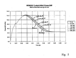
- Fig. 5
- shows a diagram illustrating the effect of the deceleration device with respect to the differential pressure.
- In the following description of the figures, the same reference characters are used for identical or similar elements.
- The following paragraphs detail the deceleration device 2, which is mounted within doorpost 15. As will become apparent from Fig. 2, the deceleration device 2 comprises a housing 7 in which the main components of the device 2 are installed. In particular, an elevating spindle 16 extends in a vertical direction and rotates in two bearings 14 which are supported on housing 7. The elevating spindle 16 may consist of two mating parts, a bearing shaft 11 and a shaft sleeve 12 featuring both right hand and left hand threads either side of a short central plain shank 17.
- The deceleration device 2 moreover comprises a spool reel 4 which surrounds the plain shank 17 of the elevating spindle 17. A belt 3 is wound up on the spool reel 4 and is connected to a buckle 5 which is positively held in position by means of two ball catches 6. The shaft assembly 11, 12 slides into the spool reel 4 and is locked to the spool reel 4 by means of a
single shear pin 8. At either end the shaft is supported by the plain bearings 14 which are in turn supported to the main housing 7. - On each side of the spool reel 4,
steel collets 10 screw down the threads of the shaft sleeve 12. Thecollets 10 may be profile milled to a rounded hexagonal shape and fit within a matching profile of the housing 7. Betweencollet 10 and housing 7 six compression springs are installed on either side of the plain shank 17 in recessed pockets in both collet and housing, such that they are held in position by thecollets 10 and the housing 7. - For example, in the event that a traction force is applied to the
buckle 20 being connected to belt 19,belt 19 will be retracted from the spool reel 4 causing the spool reel 4 to rotate. This rotation will be directly transferred (via the shear pin) to the shaft assembly. As each of thecollets 10 is captivated by its conforming profile in its respective housing 7, the rotational movement of the spool reel 4 and shaft assembly 11, 12 is transferred to the linear movement of thecollets 10. The movement of thecollets 10 is outwards from the spool reel 4 in the direction of the housing 7 such that the captivated springs are compressed along their free length. Thus for each 360° of rotation 1,5 mm of linear travel (standard 10,0 mm metric thread = 1,5 mm pitch) may be achieved. The collective spring force is set to react to a load such that a predetermined constant force is required to extract the belt 3 from the spool reel 4. For example, the springs 9 might be designed to have a constant spring rate such that the force remains constant through the angular rotation of the spool 4. However as thebelt 19 retracts from the spool 4 the diameter of the belt on spool reel 4 decreases. Hence, each successive rotation requires less length of belt due to the geometry of the belt on the spool reel 4. So by virtue of the belt geometry the reaction force to the door movement may be described as progressive. - The first rotation of the spool reel 4 does not compress the springs 9 but brings both
collets 10 into engagement. This is to allow a single free rotation of the spool reel 4 with minimal force. To this effect, a plurality of wave spring washers 18 having a negligible spring constant may be connected in series with the plurality of compression springs 9, so that during an initial rotation of the spool reel 4 minimal reaction load will be generated due to the negligible spring constant of the plurality of spring washers 18. The first complete rotation may be equivalent to the door opening by approximately 10° (belt extracted by 150mm). This first free movement is intended to allow the door 3 to open and to initially accelerate as quickly as possible so as not to adversely increase the pressure load across the door 3 and is timed to a point where the pressure load peaks and begins to fall whereas the door energy overtakes the peak pressure load and begins to accelerate rapidly (cf. Fig. 1). - Additionally, where maintenance inspection or unit failure or accidental engagement of the belt 3 occurs during normal use, the first free rotation allows the door to open sufficient to allow detachment of the belt from the cabin side. The belt is self retracting by means of a drive spring situated at one end of the shaft assembly. The drive spring is set to retract the belt by one revolution and is connected to the shaft by means of a sprung loaded gear that will slip freely on the shaft if rotation exceeds one revolution.
- The total travel of the
collet 10 along the shaft assembly may be 10,5 mm which translates to 7 full turns (760 mm of belt extension). This allows the door to rotate through to its maximum venting area at 80°. - Prior to reaching the end stop a further method of energy absorption may be employed by incorporating an energy absorbing tube 13 into the end of the
collets 10 such that thecollets 10 contact the housing 7 before the maximum travel of 10,5 mm. Hence, the force which is necessary to collapse the energy absorbing tube 13 is dissipated due to the deformation of the energy absorbing tube 13. - Finally, further kinetic energy may be absorbed from the travelling door 3 at an angle close to its maximum vent area due to the two part design of the elevating spindle 16. The shaft assembly 11, 12 is designed as two parts to allow shearing of the threaded sleeve 12 from the spool reel 4 without affecting the structural integrity of the main support bearing shaft 11. Hence, due to the relative movement of threaded sleeve 12 from the spool reel 4 shearing the single shear pin 9, further kinetic energy may be absorbed.
- The intention is to absorb the maximum energy from the travelling door throughout its rotation from 10° onwards, without adversely increasing the pressure load, whilst limiting the maximum reaction load.
- In the following, the effect of the deceleration device 2 on the door 3 will be illustrated. It can be seen from the following graph of Fig. 16 that reacting a force (normal to door plane) at the door centre of area by means of the deceleration device 2 throughout the doors rotation under decompression load will reduce the end energy. In particular:
- Reacting a load of 50daN at the door centre of area will reduce the end energy by 8% (2684J to 2473J).
- Reacting a load of 100daN at the door centre of area will reduce the end energy by 16% (2684J to 2263J).
- Reacting a load of 150daN at the door centre of area will reduce the end energy by 24% (2684J to 2054J).
- Reacting a load of 200daN at the door centre of area will reduce the end energy by 32% (2684J to 1840J).
- Reacting a load of 250daN at the door centre of area will reduce the end energy by 40% (2684J to 1630J).
- Assuming a series of reaction loads as described in the foregoing paragraph, the effect of door opening time is shown in Fig. 17. As will become apparent from Fig. 17,
- Reacting a load of 50daN at the door centre of area increases the time taken to reach the minimum venting area (80°) by 3% (0.067ms to 0.069ms);
- Reacting a load of 100daN at the door centre of area increases the time taken to reach the minimum venting area (80°) by 4.5% (0.067ms to 0.070ms);
- Reacting a load of 150daN at the door centre of area increases the time taken to reach the minimum venting area (80°) by 7.5% (0.067ms to 0.072ms);
- Reacting a load of 200daN at the door centre of area increases the time taken to reach the minimum venting area (80°) by 10.5% (0.067ms to 0.074ms);
- Reacting a load of 250daN at the door centre of area increases the time taken to reach the minimum venting area (80°) by 13% (0.067ms to 0.076ms).
- Assuming a series of reaction loads as described above, the effect on the cockpit wall pressure difference is shown in Fig. 18, which shows that
- Reacting a load of 50daN at the door centre of area increases the differential pressure by 0.67% (119 hPa to 119.8 hPa);
- Reacting a load of 100daN at the door centre of area increases the differential pressure by 1.26% (119 hPa to 120.5 hPa);
- Reacting a load of 150daN at the door centre of area increases the differential pressure by 1.85% (119 hPa to 121.2 hPa);
- Reacting a load of 200daN at the door centre of area increases the differential pressure by 2.5% (119 hPa to 122.0 hPa);
- Reacting a load of 250daN at the door centre of area increases the differential pressure by 3.2% (119hPa to 122.8hPa).
- Hence, reacting a load equivalent to 250daN at the door Centre of Area reduces the end energy by over 1000 Joules (40%) but increases the cockpit wall differential pressure by just 3.8 hPa (3.2%). Thus a method for controlling and reducing the end energy of the door without substantially increasing the pressure load upon the monuments can be realised by means of the present operation mechanism.
- The deceleration device of the present invention has been described within the context of a dissipation of kinetic energy of a cockpit door. However, the deceleration device of the present invention may be used for other purposes in other applications as well, as it will be easily understood by the skilled person.
- In addition it should be pointed out that "comprising" does not exclude other elements or steps, and "a" or "one" does not exclude a plural number. Furthermore, it should be pointed out that characteristics or steps which have been described with reference to one of the above embodiments can also be used in combination with other characteristics or steps of other embodiments described above. Reference characters in the claims are not to be interpreted as limitations.
-
- 2
- deceleration device
- 19
- belt
- 20
- buckle
- 26
- doorpost
- 104
- spool reel
- 107
- housing
- 108
- shear pin
- 109
- spring
- 110
- collet
- 111
- bearing shaft
- 112
- Shaft sleeve
- 113
- energy absorbing tube
- 114
- bearing
- 115
- elevating spindle
- 116
- plain shank
- 117
- wave spring washer
Claims (10)
- A deceleration device adapted for gradual dissipation of kinetic energy, comprising:- a spool reel (104) carrying a belt (19) being wound up on the spool reel (104);- an elevating spindle (115) being driven by the spool reel (104) when the belt (19) is being retracted from the spool reel (104);- at least one collet (110) screwed to the elevating spindle (115); and- at least one spring assembly (109) being installed between the collet (110) and a fixed bearing portion (107) of the deceleration device (2);wherein the at least one collet (110) is screwed towards the fixed bearing portion by retraction of the belt (19) from the spool reel (104) thereby compressing the spring assembly (109), whereby a reaction load is generated by the spring assembly (109) counteracting the retraction of the belt (19).
- The deceleration device according to claim 1,
wherein the spring assembly (109) comprises a plurality of compression springs (109) being situated between the collet (110) and the fixed bearing portion and surrounding the elevating spindle (115). - The deceleration device according to claim 1 or 2,
wherein the collet (110) is shaped in the form of a polygon in plan view having a plurality of rounded edges forming receptacles for the plurality of compression springs (109). - The deceleration device according to one of claims 11 to 3, the deceleration device (2) further comprising:- at least one cup-shaped housing comprising a profile matching the polygonal shape of the collet to allow the collet (110) to slide into the housing,wherein the fixed bearing portion forms part of the base of the housing, so that the plurality of compression springs (109) being situated between the base and the collet (110).
- The deceleration device according to one of claims 1 to 4,
wherein the elevating spindle (115) comprises a bearing shaft (111) being rotatably mounted in the fixed bearing portion and a threaded shaft sleeve (112) surrounding the bearing shaft (111), wherein the bearing shaft (111), the shaft sleeve (112) and the spool reel (104) surrounding the elevating spindle (115) are locked to each other by means of a single shear pin (108). - The deceleration device according to one of claims 1 to 5, the deceleration device (2) further comprising:- at least one energy absorbing tube (113) surrounding the elevating spindle (115) to come prior into contact with the fixed bearing portion than the at least one collet (110), to dissipate further energy by deformation of the at least one energy absorbing tube (113).
- The deceleration device according to one of claims 2 to 6, the deceleration device (2) further comprising:- of plurality of spring washers (117) having a negligible spring constant,wherein the plurality of spring washers (117) is connected in series with the plurality of compression springs (109), so that during an initial rotation of the spool reel (104) no reaction load will be generated due to the negligible spring constant of the plurality of spring washers (117).
- The deceleration device of claim 1,
wherein the deceleration device (2) is symmetrically designed comprising an elevating spindle (115) featuring right hand and left hand threads at either side of a central portion being surrounded by the spool reel (104), which due to a retraction force screws a first collet (110) towards a first fixed bearing portion thereby compressing a first spring assembly (109) situated between the first collet (110) and the first fixed bearing and screws a second collet (110) towards a second fixed bearing portion thereby compressing a second spring assembly (109) situated between the first collet and the first fixed bearing portion. - A cockpit door which is adapted to be connected to the deceleration device (2) according to one of claims 1 to 8 in the event of a cockpit decompression.
- An aircraft being provided with a cockpit door assembly comprising the deceleration device (2) of one of claims 1 to 8.
Priority Applications (3)
| Application Number | Priority Date | Filing Date | Title |
|---|---|---|---|
| DE200660006542 DE602006006542D1 (en) | 2006-03-08 | 2006-03-08 | decelerating |
| EP20060004706 EP1832507B1 (en) | 2006-03-08 | 2006-03-08 | Deceleration device |
| US11/715,285 US7712705B2 (en) | 2006-03-08 | 2007-03-07 | Deceleration device |
Applications Claiming Priority (1)
| Application Number | Priority Date | Filing Date | Title |
|---|---|---|---|
| EP20060004706 EP1832507B1 (en) | 2006-03-08 | 2006-03-08 | Deceleration device |
Publications (2)
| Publication Number | Publication Date |
|---|---|
| EP1832507A1 true EP1832507A1 (en) | 2007-09-12 |
| EP1832507B1 EP1832507B1 (en) | 2009-04-29 |
Family
ID=36699184
Family Applications (1)
| Application Number | Title | Priority Date | Filing Date |
|---|---|---|---|
| EP20060004706 Expired - Lifetime EP1832507B1 (en) | 2006-03-08 | 2006-03-08 | Deceleration device |
Country Status (2)
| Country | Link |
|---|---|
| EP (1) | EP1832507B1 (en) |
| DE (1) | DE602006006542D1 (en) |
Citations (5)
| Publication number | Priority date | Publication date | Assignee | Title |
|---|---|---|---|---|
| DE516627C (en) * | 1928-10-31 | 1931-01-24 | Heinrich Illig | Device for damping the vibrations of two bodies moving against one another, especially for motor vehicles |
| US2659573A (en) * | 1951-01-26 | 1953-11-17 | Sr Joel D Smith | Safety belt cable take-up and shock absorber |
| US3182935A (en) * | 1964-07-30 | 1965-05-11 | William J G Wischhoefer | Vehicle arresting gear system |
| FR2002658A1 (en) * | 1968-02-27 | 1969-10-31 | Virkki Jalmari | |
| US20050082433A1 (en) * | 2003-10-02 | 2005-04-21 | Jamco Corporation | Cockpit door of aircraft |
-
2006
- 2006-03-08 EP EP20060004706 patent/EP1832507B1/en not_active Expired - Lifetime
- 2006-03-08 DE DE200660006542 patent/DE602006006542D1/en not_active Expired - Lifetime
Patent Citations (5)
| Publication number | Priority date | Publication date | Assignee | Title |
|---|---|---|---|---|
| DE516627C (en) * | 1928-10-31 | 1931-01-24 | Heinrich Illig | Device for damping the vibrations of two bodies moving against one another, especially for motor vehicles |
| US2659573A (en) * | 1951-01-26 | 1953-11-17 | Sr Joel D Smith | Safety belt cable take-up and shock absorber |
| US3182935A (en) * | 1964-07-30 | 1965-05-11 | William J G Wischhoefer | Vehicle arresting gear system |
| FR2002658A1 (en) * | 1968-02-27 | 1969-10-31 | Virkki Jalmari | |
| US20050082433A1 (en) * | 2003-10-02 | 2005-04-21 | Jamco Corporation | Cockpit door of aircraft |
Also Published As
| Publication number | Publication date |
|---|---|
| DE602006006542D1 (en) | 2009-06-10 |
| EP1832507B1 (en) | 2009-04-29 |
Similar Documents
| Publication | Publication Date | Title |
|---|---|---|
| US7571877B2 (en) | Operation mechanism for activating a deceleration device | |
| US7712705B2 (en) | Deceleration device | |
| US3143321A (en) | Frangible tube energy dissipation | |
| EP2944562B1 (en) | Passenger aircraft with an emergency exit door | |
| US20200346743A1 (en) | Energy Absorbing Landing Systems for Aircraft | |
| CN105940237B (en) | Collision buffer | |
| US11274484B2 (en) | Door system with a deceleration mechanism | |
| CN110803285A (en) | Landing disengaging lock and automatic unlocking method | |
| US7527221B2 (en) | Mounting device for interior equipment in aircraft | |
| EP1832507B1 (en) | Deceleration device | |
| EP4033111B1 (en) | Frangible fastener system | |
| CN113624090B (en) | Explosion-proof device and aircraft | |
| JP6774762B2 (en) | Shock absorber assembly for vehicle power drive | |
| EP3636540B1 (en) | A door opening system with a deceleration mechanism | |
| US20090107324A1 (en) | Rotating suspension lug | |
| US11208837B2 (en) | Door system with a deceleration mechanism | |
| US7931428B2 (en) | Aircraft payload retention system for interior loads | |
| US6886779B2 (en) | Impact-absorbing, load-limiting connection device and rotary wing aircraft having such a connection device | |
| CN210370189U (en) | Inner handle with locking function | |
| US20250092902A1 (en) | Ball lock pin with fail-safe locking mechanism | |
| DE102020119847B4 (en) | Landing platform for an aircraft | |
| US20200270919A1 (en) | Hold Open Rod Having a Lock Mechanism for Securely Locking the Hold Open Rod in an Extended Configuration |
Legal Events
| Date | Code | Title | Description |
|---|---|---|---|
| PUAI | Public reference made under article 153(3) epc to a published international application that has entered the european phase |
Free format text: ORIGINAL CODE: 0009012 |
|
| AK | Designated contracting states |
Kind code of ref document: A1 Designated state(s): AT BE BG CH CY CZ DE DK EE ES FI FR GB GR HU IE IS IT LI LT LU LV MC NL PL PT RO SE SI SK TR |
|
| AX | Request for extension of the european patent |
Extension state: AL BA HR MK YU |
|
| 17P | Request for examination filed |
Effective date: 20080220 |
|
| AKX | Designation fees paid |
Designated state(s): DE FR GB IT SE |
|
| 17Q | First examination report despatched |
Effective date: 20080620 |
|
| GRAP | Despatch of communication of intention to grant a patent |
Free format text: ORIGINAL CODE: EPIDOSNIGR1 |
|
| GRAS | Grant fee paid |
Free format text: ORIGINAL CODE: EPIDOSNIGR3 |
|
| GRAA | (expected) grant |
Free format text: ORIGINAL CODE: 0009210 |
|
| AK | Designated contracting states |
Kind code of ref document: B1 Designated state(s): DE FR GB IT SE |
|
| REG | Reference to a national code |
Ref country code: GB Ref legal event code: FG4D |
|
| REF | Corresponds to: |
Ref document number: 602006006542 Country of ref document: DE Date of ref document: 20090610 Kind code of ref document: P |
|
| REG | Reference to a national code |
Ref country code: SE Ref legal event code: TRGR |
|
| PLBE | No opposition filed within time limit |
Free format text: ORIGINAL CODE: 0009261 |
|
| STAA | Information on the status of an ep patent application or granted ep patent |
Free format text: STATUS: NO OPPOSITION FILED WITHIN TIME LIMIT |
|
| 26N | No opposition filed |
Effective date: 20100201 |
|
| REG | Reference to a national code |
Ref country code: FR Ref legal event code: CD Owner name: AIRBUS OPERATIONS GMBH Effective date: 20111118 |
|
| REG | Reference to a national code |
Ref country code: FR Ref legal event code: PLFP Year of fee payment: 11 |
|
| PGFP | Annual fee paid to national office [announced via postgrant information from national office to epo] |
Ref country code: GB Payment date: 20160321 Year of fee payment: 11 Ref country code: SE Payment date: 20160321 Year of fee payment: 11 |
|
| PGFP | Annual fee paid to national office [announced via postgrant information from national office to epo] |
Ref country code: IT Payment date: 20160324 Year of fee payment: 11 |
|
| REG | Reference to a national code |
Ref country code: DE Ref legal event code: R082 Ref document number: 602006006542 Country of ref document: DE Representative=s name: LKGLOBAL | LORENZ & KOPF PARTG MBB PATENTANWAE, DE Ref country code: DE Ref legal event code: R082 Ref document number: 602006006542 Country of ref document: DE Representative=s name: KOPF WESTENBERGER WACHENHAUSEN PATENTANWAELTE , DE |
|
| REG | Reference to a national code |
Ref country code: FR Ref legal event code: PLFP Year of fee payment: 12 |
|
| REG | Reference to a national code |
Ref country code: SE Ref legal event code: EUG |
|
| GBPC | Gb: european patent ceased through non-payment of renewal fee |
Effective date: 20170308 |
|
| PG25 | Lapsed in a contracting state [announced via postgrant information from national office to epo] |
Ref country code: SE Free format text: LAPSE BECAUSE OF NON-PAYMENT OF DUE FEES Effective date: 20170309 |
|
| PG25 | Lapsed in a contracting state [announced via postgrant information from national office to epo] |
Ref country code: IT Free format text: LAPSE BECAUSE OF NON-PAYMENT OF DUE FEES Effective date: 20170308 Ref country code: GB Free format text: LAPSE BECAUSE OF NON-PAYMENT OF DUE FEES Effective date: 20170308 |
|
| REG | Reference to a national code |
Ref country code: FR Ref legal event code: PLFP Year of fee payment: 13 |
|
| PGFP | Annual fee paid to national office [announced via postgrant information from national office to epo] |
Ref country code: DE Payment date: 20200320 Year of fee payment: 15 |
|
| REG | Reference to a national code |
Ref country code: DE Ref legal event code: R119 Ref document number: 602006006542 Country of ref document: DE |
|
| PG25 | Lapsed in a contracting state [announced via postgrant information from national office to epo] |
Ref country code: DE Free format text: LAPSE BECAUSE OF NON-PAYMENT OF DUE FEES Effective date: 20211001 |
|
| PGFP | Annual fee paid to national office [announced via postgrant information from national office to epo] |
Ref country code: FR Payment date: 20220322 Year of fee payment: 17 |
|
| PG25 | Lapsed in a contracting state [announced via postgrant information from national office to epo] |
Ref country code: FR Free format text: LAPSE BECAUSE OF NON-PAYMENT OF DUE FEES Effective date: 20230331 |