EP1832435B1 - Process for marking surfaces by laser - Google Patents
Process for marking surfaces by laser Download PDFInfo
- Publication number
- EP1832435B1 EP1832435B1 EP07380059A EP07380059A EP1832435B1 EP 1832435 B1 EP1832435 B1 EP 1832435B1 EP 07380059 A EP07380059 A EP 07380059A EP 07380059 A EP07380059 A EP 07380059A EP 1832435 B1 EP1832435 B1 EP 1832435B1
- Authority
- EP
- European Patent Office
- Prior art keywords
- marking
- points
- laser
- individual
- characters
- Prior art date
- Legal status (The legal status is an assumption and is not a legal conclusion. Google has not performed a legal analysis and makes no representation as to the accuracy of the status listed.)
- Not-in-force
Links
- 238000000034 method Methods 0.000 title claims abstract description 23
- 238000005286 illumination Methods 0.000 abstract description 2
- 238000002679 ablation Methods 0.000 description 4
- 239000000463 material Substances 0.000 description 3
- 239000002184 metal Substances 0.000 description 3
- 229910052751 metal Inorganic materials 0.000 description 3
- 239000003973 paint Substances 0.000 description 3
- 239000002344 surface layer Substances 0.000 description 3
- 238000010330 laser marking Methods 0.000 description 2
- 238000002844 melting Methods 0.000 description 2
- 230000008018 melting Effects 0.000 description 2
- 239000000126 substance Substances 0.000 description 2
- 230000000007 visual effect Effects 0.000 description 2
- 230000001174 ascending effect Effects 0.000 description 1
- 239000011521 glass Substances 0.000 description 1
- 239000010410 layer Substances 0.000 description 1
- 238000004519 manufacturing process Methods 0.000 description 1
- 150000002739 metals Chemical class 0.000 description 1
- 230000003287 optical effect Effects 0.000 description 1
- 238000000926 separation method Methods 0.000 description 1
- 239000012780 transparent material Substances 0.000 description 1
Images


Classifications
-
- B—PERFORMING OPERATIONS; TRANSPORTING
- B41—PRINTING; LINING MACHINES; TYPEWRITERS; STAMPS
- B41M—PRINTING, DUPLICATING, MARKING, OR COPYING PROCESSES; COLOUR PRINTING
- B41M5/00—Duplicating or marking methods; Sheet materials for use therein
- B41M5/24—Ablative recording, e.g. by burning marks; Spark recording
-
- B—PERFORMING OPERATIONS; TRANSPORTING
- B41—PRINTING; LINING MACHINES; TYPEWRITERS; STAMPS
- B41M—PRINTING, DUPLICATING, MARKING, OR COPYING PROCESSES; COLOUR PRINTING
- B41M5/00—Duplicating or marking methods; Sheet materials for use therein
- B41M5/26—Thermography ; Marking by high energetic means, e.g. laser otherwise than by burning, and characterised by the material used
Definitions
- the present invention relates to a process for marking surfaces by the application of laser beams.
- the laser beam marking equipment has means for storing information relating to different types of marking characters, means for selecting the different types of marking, means for controlling the movements of the laser beam projector unit apart from the laser beam projector itself, which may be of the type provided with galvanometers.
- the process performed by the equipment consists of interpreting instructions on the types of writing and lettering to use so that the equipment control device generates instructions for moving the laser beam projector and switching on and off said laser beam projector to perform the marking to be produced.
- the different processes will be used optionally by the technician depending on the characteristics of the surface on which marking is required.
- surfaces that allow a chemical change of colour do not necessarily require an ablation process and surfaces with a surface layer of paint require a special process for the local removal of said layer of paint to form the characters or signs.
- the surfaces of materials such as glass or metal will preferably be marked by ablation, a process in which material is specifically removed in the part of the surface to be marked according to the characteristics of the laser beam projected.
- US Patent application publication n° 2005/0123864 A1 discloses a system to convert graphic images converting an image by means of progressively smaller contours of the image.
- the contours are defined by continuous lines with points therealong.
- US Patent 6400037 discloses a marking method in which each sign is made by melting of the surface layer of the metal, which is re-solidified and smoothed to differentiate a mirror-like surface from the areas engaged by melting.
- the visual impression is one of very little contrast. This occurs mainly on transparent materials marked by laser, but also on metals, etc. This optical effect is produced by light reflection, reflected only in the direction of the vector, and as a result the visual marking is poor.
- the inventors have developed a new process to which the present invention relates, based fundamentally on marking characters avoiding the continuous tracing currently known which produces little distinction by light reflection on lines produced individually by the laser device, by substituting said marking for marking by individual points which successively form each of the sections of the characters or signs to be marked. Accordingly the different points corresponding to each character are defined in such a way that the number of points, their separation and the characteristics of the points for each character to be marked are predetermined.
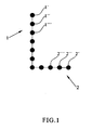
- the process according to the present invention is based on substituting the individual determinant outlines of a written character, for example, the arms -1- and -2- of a letter, in the case illustrated the letter "L", for respective series of individual points such as the points -1'-, -1"-, -1-"', etc. for the arm -1- and the points -2'-, -2"-, -2"'-, etc. for the arm -2- of said character.
- the number of points will be defined beforehand so that the characters or character source of the system will comprise the definition of the individual characters by series of points that are predetermined in number, arrangement and characteristics, for example, the marking trajectories, to obtain characters with a great capacity to reflect the ambient light in different directions which, as has been proven experimentally, very significantly increases the visibility of the marking.
- FIG. 2 An illustration of the process described can be seen in Fig. 2 , showing the power applied in ordinates and the process time in abscissae.
- a waiting period -4- to improve the precision of point positioning and avoid imprecision due to inertia and times of increased power, moving next to the specific marking period -5- in which the maximum power indicated by the abscissa -6- is reached after an ascending curve -7-, which then descends following the curve -8- to no power, in other words, the switched-off position.
- the process continues for another period -9- of movement and a waiting period -10- to another marking period -11- and so on.
- the values of the different parameters for different signs will have been predetermined and stored in the control equipment of the laser equipment so that they can be selected at the required time, to produce the specific marking required.
- the process according to the present invention can also be applied to marking applications such as two-dimensional code, using the same process, allowing very high precision marking to be performed owing to the application of the waiting time between each two marking points.
- a two-dimensional figure -12- has been shown arranged on a rectangular frame with sides -13- and -14-, each individual outline having also been defined in said Fig. by means of series of predetermined points similar to what has been indicated above.
- the operation would basically be the same as has been indicated for the marking of each of the points, after its corresponding period of movement and waiting.
Landscapes
- Physics & Mathematics (AREA)
- Optics & Photonics (AREA)
- Laser Beam Processing (AREA)
- Treatment Of Fiber Materials (AREA)
Abstract
Description
- The present invention relates to a process for marking surfaces by the application of laser beams.
- As is already known, marking different types of surface is of great industrial interest as in many types of manufacture there is a requirement to mark the article on its surface. To solve the problem of marking the article surfaces, where it may be difficult to achieve permanent marking, laser marking processes have been used for a long time. These processes produce marking by means of a laser beam projector which controls the laser beam itself in such a way that the selected path to outline the characters is travelled. In other words, lines are traced using a particular model of direction, length and form, to suit the different characters or signs to be traced. To do this, the laser beam marking equipment has means for storing information relating to different types of marking characters, means for selecting the different types of marking, means for controlling the movements of the laser beam projector unit apart from the laser beam projector itself, which may be of the type provided with galvanometers. The process performed by the equipment consists of interpreting instructions on the types of writing and lettering to use so that the equipment control device generates instructions for moving the laser beam projector and switching on and off said laser beam projector to perform the marking to be produced.
- With the equipment and methods currently known laser marking of the required surface can be carried out by any of three processes.
- Ablation
- Chemical change of colour
- Removing a surface layer of paint
- Clearly, the different processes will be used optionally by the technician depending on the characteristics of the surface on which marking is required. Thus, for example, surfaces that allow a chemical change of colour do not necessarily require an ablation process and surfaces with a surface layer of paint require a special process for the local removal of said layer of paint to form the characters or signs. However, the surfaces of materials such as glass or metal will preferably be marked by ablation, a process in which material is specifically removed in the part of the surface to be marked according to the characteristics of the laser beam projected.
-
US Patent application publication n° 2005/0123864 A1 discloses a system to convert graphic images converting an image by means of progressively smaller contours of the image. The contours are defined by continuous lines with points therealong. -
US Patent 6400037 discloses a marking method in which each sign is made by melting of the surface layer of the metal, which is re-solidified and smoothed to differentiate a mirror-like surface from the areas engaged by melting. - In the case of ablation the main problem is that despite having penetrated deep into the material, the visual impression is one of very little contrast. This occurs mainly on transparent materials marked by laser, but also on metals, etc. This optical effect is produced by light reflection, reflected only in the direction of the vector, and as a result the visual marking is poor.
- To avoid the aforementioned problem and achieve satisfactory marking from the point of view of the ability to see the marked signs in spite of the existing ambient light, the inventors have developed a new process to which the present invention relates, based fundamentally on marking characters avoiding the continuous tracing currently known which produces little distinction by light reflection on lines produced individually by the laser device, by substituting said marking for marking by individual points which successively form each of the sections of the characters or signs to be marked. Accordingly the different points corresponding to each character are defined in such a way that the number of points, their separation and the characteristics of the points for each character to be marked are predetermined. In this way the individual characters are determined for each section of their outline, by series of previously determined points which reflect light in a plurality of directions, producing a much more visible result, which improves marking quality, since ultimately this quality can be defined by the ability to be read in the ambient illumination.
- The invention will be better understood with the help of the accompanying drawings illustrating the present process, given as an explanatory but not limiting example.
-
Fig. 1 shows diagrammatically the outline of a letter according to the present process. -
Fig. 2 also shows diagrammatically the functional operation of marking according to the present invention. -
Fig. 3 also shows diagrammatically a marking application for two-dimensional code. - As illustrated in
Fig. 1 , the process according to the present invention is based on substituting the individual determinant outlines of a written character, for example, the arms -1- and -2- of a letter, in the case illustrated the letter "L", for respective series of individual points such as the points -1'-, -1"-, -1-"', etc. for the arm -1- and the points -2'-, -2"-, -2"'-, etc. for the arm -2- of said character. The number of points will be defined beforehand so that the characters or character source of the system will comprise the definition of the individual characters by series of points that are predetermined in number, arrangement and characteristics, for example, the marking trajectories, to obtain characters with a great capacity to reflect the ambient light in different directions which, as has been proven experimentally, very significantly increases the visibility of the marking. - When marking by laser with galvanometers the following operations are carried out, using the previously determined character source described in outline above:
- the galvanometer is moved to the marking position for the first point (moving)
- a waiting time is defined to ensure that the galvanometer is in the correct position (wait)
- emission of the beam begins for an adjustable period (dot)
- the galvanometer is moved to the marking position for the second point (moving)
- and so on for all the points that make up the marking.
- An illustration of the process described can be seen in
Fig. 2 , showing the power applied in ordinates and the process time in abscissae. Thus, for example, starting from a first time period -3- when the galvanometer moves, there will be a waiting period -4- to improve the precision of point positioning and avoid imprecision due to inertia and times of increased power, moving next to the specific marking period -5- in which the maximum power indicated by the abscissa -6- is reached after an ascending curve -7-, which then descends following the curve -8- to no power, in other words, the switched-off position. Next, the process continues for another period -9- of movement and a waiting period -10- to another marking period -11- and so on. - As has been shown, the values of the different parameters for different signs, for example, alphanumeric signs, will have been predetermined and stored in the control equipment of the laser equipment so that they can be selected at the required time, to produce the specific marking required.
- The process according to the present invention can also be applied to marking applications such as two-dimensional code, using the same process, allowing very high precision marking to be performed owing to the application of the waiting time between each two marking points. For example, in
Fig. 3 a two-dimensional figure -12- has been shown arranged on a rectangular frame with sides -13- and -14-, each individual outline having also been defined in said Fig. by means of series of predetermined points similar to what has been indicated above. Clearly, the operation would basically be the same as has been indicated for the marking of each of the points, after its corresponding period of movement and waiting. - As will be understood, although the invention makes known the functional examples illustrated and described above, it is not limited to these examples but on the contrary, may be extended to many other variants included within the scope of the following claims including the introduction of equivalent elements.
Claims (1)
- Process for marking surfaces by laser whereby :a) Signs or characters are to be marked on a surface;b) The outlines of the signs or characters are substituted by series of individual points whereby the number, arrangement and characteristics of the points are predetermined in order that the points, once created, will reflect ambient light in different directions;c) The values of the parameters for the points are stored in the control equipment of the laser equipment andd) The specific marking required is created by laser.
Applications Claiming Priority (1)
| Application Number | Priority Date | Filing Date | Title |
|---|---|---|---|
| ES200600554A ES2325608B1 (en) | 2006-03-07 | 2006-03-07 | PROCEDURE FOR MARKING SURFACES THROUGH LASER. |
Publications (3)
| Publication Number | Publication Date |
|---|---|
| EP1832435A2 EP1832435A2 (en) | 2007-09-12 |
| EP1832435A3 EP1832435A3 (en) | 2010-06-23 |
| EP1832435B1 true EP1832435B1 (en) | 2012-04-11 |
Family
ID=38091771
Family Applications (1)
| Application Number | Title | Priority Date | Filing Date |
|---|---|---|---|
| EP07380059A Not-in-force EP1832435B1 (en) | 2006-03-07 | 2007-03-05 | Process for marking surfaces by laser |
Country Status (3)
| Country | Link |
|---|---|
| EP (1) | EP1832435B1 (en) |
| AT (1) | ATE552983T1 (en) |
| ES (2) | ES2325608B1 (en) |
Family Cites Families (7)
| Publication number | Priority date | Publication date | Assignee | Title |
|---|---|---|---|---|
| JPH02211989A (en) * | 1989-02-10 | 1990-08-23 | Nec Corp | Method for controlling dot interval at time of finishing laser beam marking |
| JPH03208678A (en) * | 1990-01-12 | 1991-09-11 | Komatsu Ltd | Scanning type liquid crystal mask printing device and scanning method |
| JPH0732168A (en) * | 1993-07-20 | 1995-02-03 | Hitachi Ltd | Pulse control printing method and device |
| JP3406817B2 (en) * | 1997-11-28 | 2003-05-19 | 株式会社東芝 | Method for marking metal layer and semiconductor device |
| US6819349B2 (en) * | 2000-11-14 | 2004-11-16 | Toto Ltd. | Mark forming method and product using the same method |
| US6753501B1 (en) * | 2001-11-03 | 2004-06-22 | Darryl Costin, Sr. | Processing of textile materials using laser beams and material sized in larger widths |
| US6958762B2 (en) * | 2003-12-09 | 2005-10-25 | Markem Corporation | Filling an area of an image marked on a material with a laser |
-
2006
- 2006-03-07 ES ES200600554A patent/ES2325608B1/en not_active Expired - Fee Related
-
2007
- 2007-03-05 AT AT07380059T patent/ATE552983T1/en active
- 2007-03-05 EP EP07380059A patent/EP1832435B1/en not_active Not-in-force
- 2007-03-05 ES ES07380059T patent/ES2385675T3/en active Active
Also Published As
| Publication number | Publication date |
|---|---|
| EP1832435A2 (en) | 2007-09-12 |
| ES2325608B1 (en) | 2010-06-10 |
| ATE552983T1 (en) | 2012-04-15 |
| EP1832435A3 (en) | 2010-06-23 |
| ES2385675T3 (en) | 2012-07-30 |
| ES2325608A1 (en) | 2009-09-09 |
Similar Documents
| Publication | Publication Date | Title |
|---|---|---|
| US8232502B2 (en) | Laser engraving of ceramic articles | |
| EP0854761B1 (en) | Co2 laser marking of coated surfaces for product identification | |
| US4467525A (en) | Automated sign generator | |
| CA2444109A1 (en) | Method for laser beam-assisted application of metal ions in glass for producing colorless and color pixels | |
| US10124442B2 (en) | Colour marking metal surfaces | |
| CA2097744C (en) | Marking apparatus with multiple marking modes | |
| KR20150110071A (en) | Laser marking apparatus for Large Area | |
| US11524360B2 (en) | Marking system for decorating workpieces | |
| CN2557432Y (en) | High-speed laser mark-making machine | |
| WO1989007302A1 (en) | Method of marking an object using a laser beam, and method and device for use in reading a machine-readable data marking | |
| US20110181680A1 (en) | Method for laser marking and device for carrying out said method | |
| EP1832435A2 (en) | Process for marking surfaces by laser | |
| CN111983896B (en) | High-precision alignment method for 3D exposure machine | |
| JP2002178173A (en) | Laser marking method and apparatus | |
| CN201807491U (en) | Casting blank identification system | |
| CN106042613A (en) | Solder paste printer and printing method thereof | |
| JP2021181112A (en) | Laser color marking device | |
| TW201703911A (en) | Image-rendering device | |
| Raikar et al. | Open source LaserGRBL–Arduino based laser engraver | |
| JPS61283101A (en) | Impartment of display to electronic component | |
| EP2921306B1 (en) | Load estimation apparatus, laser light irradiation system, and load estimation method | |
| TWM583788U (en) | Laser marking system for continuous bounded marking | |
| JP2010240924A (en) | Marking system | |
| FI12112U1 (en) | Educational equipment for Braille | |
| JP6433106B1 (en) | Printing method |
Legal Events
| Date | Code | Title | Description |
|---|---|---|---|
| PUAI | Public reference made under article 153(3) epc to a published international application that has entered the european phase |
Free format text: ORIGINAL CODE: 0009012 |
|
| AK | Designated contracting states |
Kind code of ref document: A2 Designated state(s): AT BE BG CH CY CZ DE DK EE ES FI FR GB GR HU IE IS IT LI LT LU LV MC MT NL PL PT RO SE SI SK TR |
|
| AX | Request for extension of the european patent |
Extension state: AL BA HR MK YU |
|
| PUAL | Search report despatched |
Free format text: ORIGINAL CODE: 0009013 |
|
| AK | Designated contracting states |
Kind code of ref document: A3 Designated state(s): AT BE BG CH CY CZ DE DK EE ES FI FR GB GR HU IE IS IT LI LT LU LV MC MT NL PL PT RO SE SI SK TR |
|
| AX | Request for extension of the european patent |
Extension state: AL BA HR MK RS |
|
| 17P | Request for examination filed |
Effective date: 20101221 |
|
| AKX | Designation fees paid |
Designated state(s): AT BE BG CH CY CZ DE DK EE ES FI FR GB GR HU IE IS IT LI LT LU LV MC MT NL PL PT RO SE SI SK TR |
|
| 17Q | First examination report despatched |
Effective date: 20110627 |
|
| GRAP | Despatch of communication of intention to grant a patent |
Free format text: ORIGINAL CODE: EPIDOSNIGR1 |
|
| GRAS | Grant fee paid |
Free format text: ORIGINAL CODE: EPIDOSNIGR3 |
|
| GRAA | (expected) grant |
Free format text: ORIGINAL CODE: 0009210 |
|
| AK | Designated contracting states |
Kind code of ref document: B1 Designated state(s): AT BE BG CH CY CZ DE DK EE ES FI FR GB GR HU IE IS IT LI LT LU LV MC MT NL PL PT RO SE SI SK TR |
|
| REG | Reference to a national code |
Ref country code: GB Ref legal event code: FG4D |
|
| REG | Reference to a national code |
Ref country code: CH Ref legal event code: EP |
|
| REG | Reference to a national code |
Ref country code: AT Ref legal event code: REF Ref document number: 552983 Country of ref document: AT Kind code of ref document: T Effective date: 20120415 |
|
| REG | Reference to a national code |
Ref country code: IE Ref legal event code: FG4D |
|
| REG | Reference to a national code |
Ref country code: DE Ref legal event code: R096 Ref document number: 602007021867 Country of ref document: DE Effective date: 20120606 |
|
| REG | Reference to a national code |
Ref country code: ES Ref legal event code: FG2A Ref document number: 2385675 Country of ref document: ES Kind code of ref document: T3 Effective date: 20120730 |
|
| REG | Reference to a national code |
Ref country code: NL Ref legal event code: VDEP Effective date: 20120411 |
|
| REG | Reference to a national code |
Ref country code: AT Ref legal event code: MK05 Ref document number: 552983 Country of ref document: AT Kind code of ref document: T Effective date: 20120411 |
|
| LTIE | Lt: invalidation of european patent or patent extension |
Effective date: 20120411 |
|
| PG25 | Lapsed in a contracting state [announced via postgrant information from national office to epo] |
Ref country code: CY Free format text: LAPSE BECAUSE OF FAILURE TO SUBMIT A TRANSLATION OF THE DESCRIPTION OR TO PAY THE FEE WITHIN THE PRESCRIBED TIME-LIMIT Effective date: 20120411 Ref country code: IS Free format text: LAPSE BECAUSE OF FAILURE TO SUBMIT A TRANSLATION OF THE DESCRIPTION OR TO PAY THE FEE WITHIN THE PRESCRIBED TIME-LIMIT Effective date: 20120811 Ref country code: SE Free format text: LAPSE BECAUSE OF FAILURE TO SUBMIT A TRANSLATION OF THE DESCRIPTION OR TO PAY THE FEE WITHIN THE PRESCRIBED TIME-LIMIT Effective date: 20120411 Ref country code: FI Free format text: LAPSE BECAUSE OF FAILURE TO SUBMIT A TRANSLATION OF THE DESCRIPTION OR TO PAY THE FEE WITHIN THE PRESCRIBED TIME-LIMIT Effective date: 20120411 Ref country code: PL Free format text: LAPSE BECAUSE OF FAILURE TO SUBMIT A TRANSLATION OF THE DESCRIPTION OR TO PAY THE FEE WITHIN THE PRESCRIBED TIME-LIMIT Effective date: 20120411 Ref country code: LT Free format text: LAPSE BECAUSE OF FAILURE TO SUBMIT A TRANSLATION OF THE DESCRIPTION OR TO PAY THE FEE WITHIN THE PRESCRIBED TIME-LIMIT Effective date: 20120411 |
|
| PG25 | Lapsed in a contracting state [announced via postgrant information from national office to epo] |
Ref country code: PT Free format text: LAPSE BECAUSE OF FAILURE TO SUBMIT A TRANSLATION OF THE DESCRIPTION OR TO PAY THE FEE WITHIN THE PRESCRIBED TIME-LIMIT Effective date: 20120813 Ref country code: LV Free format text: LAPSE BECAUSE OF FAILURE TO SUBMIT A TRANSLATION OF THE DESCRIPTION OR TO PAY THE FEE WITHIN THE PRESCRIBED TIME-LIMIT Effective date: 20120411 Ref country code: GR Free format text: LAPSE BECAUSE OF FAILURE TO SUBMIT A TRANSLATION OF THE DESCRIPTION OR TO PAY THE FEE WITHIN THE PRESCRIBED TIME-LIMIT Effective date: 20120712 Ref country code: SI Free format text: LAPSE BECAUSE OF FAILURE TO SUBMIT A TRANSLATION OF THE DESCRIPTION OR TO PAY THE FEE WITHIN THE PRESCRIBED TIME-LIMIT Effective date: 20120411 |
|
| PG25 | Lapsed in a contracting state [announced via postgrant information from national office to epo] |
Ref country code: BE Free format text: LAPSE BECAUSE OF FAILURE TO SUBMIT A TRANSLATION OF THE DESCRIPTION OR TO PAY THE FEE WITHIN THE PRESCRIBED TIME-LIMIT Effective date: 20120411 |
|
| PG25 | Lapsed in a contracting state [announced via postgrant information from national office to epo] |
Ref country code: RO Free format text: LAPSE BECAUSE OF FAILURE TO SUBMIT A TRANSLATION OF THE DESCRIPTION OR TO PAY THE FEE WITHIN THE PRESCRIBED TIME-LIMIT Effective date: 20120411 Ref country code: SK Free format text: LAPSE BECAUSE OF FAILURE TO SUBMIT A TRANSLATION OF THE DESCRIPTION OR TO PAY THE FEE WITHIN THE PRESCRIBED TIME-LIMIT Effective date: 20120411 Ref country code: CZ Free format text: LAPSE BECAUSE OF FAILURE TO SUBMIT A TRANSLATION OF THE DESCRIPTION OR TO PAY THE FEE WITHIN THE PRESCRIBED TIME-LIMIT Effective date: 20120411 Ref country code: NL Free format text: LAPSE BECAUSE OF FAILURE TO SUBMIT A TRANSLATION OF THE DESCRIPTION OR TO PAY THE FEE WITHIN THE PRESCRIBED TIME-LIMIT Effective date: 20120411 Ref country code: AT Free format text: LAPSE BECAUSE OF FAILURE TO SUBMIT A TRANSLATION OF THE DESCRIPTION OR TO PAY THE FEE WITHIN THE PRESCRIBED TIME-LIMIT Effective date: 20120411 Ref country code: DK Free format text: LAPSE BECAUSE OF FAILURE TO SUBMIT A TRANSLATION OF THE DESCRIPTION OR TO PAY THE FEE WITHIN THE PRESCRIBED TIME-LIMIT Effective date: 20120411 Ref country code: EE Free format text: LAPSE BECAUSE OF FAILURE TO SUBMIT A TRANSLATION OF THE DESCRIPTION OR TO PAY THE FEE WITHIN THE PRESCRIBED TIME-LIMIT Effective date: 20120411 |
|
| PLBE | No opposition filed within time limit |
Free format text: ORIGINAL CODE: 0009261 |
|
| STAA | Information on the status of an ep patent application or granted ep patent |
Free format text: STATUS: NO OPPOSITION FILED WITHIN TIME LIMIT |
|
| 26N | No opposition filed |
Effective date: 20130114 |
|
| REG | Reference to a national code |
Ref country code: DE Ref legal event code: R097 Ref document number: 602007021867 Country of ref document: DE Effective date: 20130114 |
|
| PG25 | Lapsed in a contracting state [announced via postgrant information from national office to epo] |
Ref country code: BG Free format text: LAPSE BECAUSE OF FAILURE TO SUBMIT A TRANSLATION OF THE DESCRIPTION OR TO PAY THE FEE WITHIN THE PRESCRIBED TIME-LIMIT Effective date: 20120711 |
|
| PG25 | Lapsed in a contracting state [announced via postgrant information from national office to epo] |
Ref country code: MC Free format text: LAPSE BECAUSE OF NON-PAYMENT OF DUE FEES Effective date: 20130331 |
|
| REG | Reference to a national code |
Ref country code: CH Ref legal event code: PL |
|
| REG | Reference to a national code |
Ref country code: IE Ref legal event code: MM4A |
|
| PG25 | Lapsed in a contracting state [announced via postgrant information from national office to epo] |
Ref country code: IE Free format text: LAPSE BECAUSE OF NON-PAYMENT OF DUE FEES Effective date: 20130305 Ref country code: LI Free format text: LAPSE BECAUSE OF NON-PAYMENT OF DUE FEES Effective date: 20130331 Ref country code: CH Free format text: LAPSE BECAUSE OF NON-PAYMENT OF DUE FEES Effective date: 20130331 |
|
| PG25 | Lapsed in a contracting state [announced via postgrant information from national office to epo] |
Ref country code: MT Free format text: LAPSE BECAUSE OF FAILURE TO SUBMIT A TRANSLATION OF THE DESCRIPTION OR TO PAY THE FEE WITHIN THE PRESCRIBED TIME-LIMIT Effective date: 20120411 |
|
| REG | Reference to a national code |
Ref country code: FR Ref legal event code: PLFP Year of fee payment: 9 |
|
| PGFP | Annual fee paid to national office [announced via postgrant information from national office to epo] |
Ref country code: IT Payment date: 20150320 Year of fee payment: 9 Ref country code: ES Payment date: 20150130 Year of fee payment: 9 Ref country code: DE Payment date: 20150319 Year of fee payment: 9 |
|
| PGFP | Annual fee paid to national office [announced via postgrant information from national office to epo] |
Ref country code: GB Payment date: 20150320 Year of fee payment: 9 |
|
| PG25 | Lapsed in a contracting state [announced via postgrant information from national office to epo] |
Ref country code: TR Free format text: LAPSE BECAUSE OF FAILURE TO SUBMIT A TRANSLATION OF THE DESCRIPTION OR TO PAY THE FEE WITHIN THE PRESCRIBED TIME-LIMIT Effective date: 20120411 |
|
| PG25 | Lapsed in a contracting state [announced via postgrant information from national office to epo] |
Ref country code: HU Free format text: LAPSE BECAUSE OF FAILURE TO SUBMIT A TRANSLATION OF THE DESCRIPTION OR TO PAY THE FEE WITHIN THE PRESCRIBED TIME-LIMIT; INVALID AB INITIO Effective date: 20070305 Ref country code: LU Free format text: LAPSE BECAUSE OF NON-PAYMENT OF DUE FEES Effective date: 20130305 |
|
| PGFP | Annual fee paid to national office [announced via postgrant information from national office to epo] |
Ref country code: FR Payment date: 20150327 Year of fee payment: 9 |
|
| REG | Reference to a national code |
Ref country code: DE Ref legal event code: R119 Ref document number: 602007021867 Country of ref document: DE |
|
| GBPC | Gb: european patent ceased through non-payment of renewal fee |
Effective date: 20160305 |
|
| REG | Reference to a national code |
Ref country code: FR Ref legal event code: ST Effective date: 20161130 |
|
| PG25 | Lapsed in a contracting state [announced via postgrant information from national office to epo] |
Ref country code: DE Free format text: LAPSE BECAUSE OF NON-PAYMENT OF DUE FEES Effective date: 20161001 Ref country code: FR Free format text: LAPSE BECAUSE OF NON-PAYMENT OF DUE FEES Effective date: 20160331 Ref country code: GB Free format text: LAPSE BECAUSE OF NON-PAYMENT OF DUE FEES Effective date: 20160305 |
|
| PG25 | Lapsed in a contracting state [announced via postgrant information from national office to epo] |
Ref country code: IT Free format text: LAPSE BECAUSE OF NON-PAYMENT OF DUE FEES Effective date: 20160305 |
|
| PG25 | Lapsed in a contracting state [announced via postgrant information from national office to epo] |
Ref country code: ES Free format text: LAPSE BECAUSE OF NON-PAYMENT OF DUE FEES Effective date: 20160306 |
|
| REG | Reference to a national code |
Ref country code: ES Ref legal event code: FD2A Effective date: 20181207 |