EP1832396A1 - Handle assembly for tool - Google Patents
Handle assembly for tool Download PDFInfo
- Publication number
- EP1832396A1 EP1832396A1 EP07111374A EP07111374A EP1832396A1 EP 1832396 A1 EP1832396 A1 EP 1832396A1 EP 07111374 A EP07111374 A EP 07111374A EP 07111374 A EP07111374 A EP 07111374A EP 1832396 A1 EP1832396 A1 EP 1832396A1
- Authority
- EP
- European Patent Office
- Prior art keywords
- handle
- tool
- gel
- chamber
- drill
- Prior art date
- Legal status (The legal status is an assumption and is not a legal conclusion. Google has not performed a legal analysis and makes no representation as to the accuracy of the status listed.)
- Granted
Links
- 239000000463 material Substances 0.000 claims abstract description 29
- 230000007704 transition Effects 0.000 claims description 6
- 238000013016 damping Methods 0.000 abstract description 21
- 230000008901 benefit Effects 0.000 description 9
- 238000004519 manufacturing process Methods 0.000 description 4
- 230000000712 assembly Effects 0.000 description 3
- 238000000429 assembly Methods 0.000 description 3
- 239000004033 plastic Substances 0.000 description 3
- 229920003023 plastic Polymers 0.000 description 3
- 238000009423 ventilation Methods 0.000 description 3
- 239000004433 Thermoplastic polyurethane Substances 0.000 description 2
- 239000002783 friction material Substances 0.000 description 2
- 238000000034 method Methods 0.000 description 2
- 229920002635 polyurethane Polymers 0.000 description 2
- 239000004814 polyurethane Substances 0.000 description 2
- 229920002725 thermoplastic elastomer Polymers 0.000 description 2
- 229920002803 thermoplastic polyurethane Polymers 0.000 description 2
- 230000004075 alteration Effects 0.000 description 1
- 238000010276 construction Methods 0.000 description 1
- 238000001816 cooling Methods 0.000 description 1
- 230000009977 dual effect Effects 0.000 description 1
- 239000013536 elastomeric material Substances 0.000 description 1
- 230000004048 modification Effects 0.000 description 1
- 238000012986 modification Methods 0.000 description 1
- 238000000465 moulding Methods 0.000 description 1
- 229920002379 silicone rubber Polymers 0.000 description 1
- 239000004945 silicone rubber Substances 0.000 description 1
- 239000007787 solid Substances 0.000 description 1
- 230000002459 sustained effect Effects 0.000 description 1
- 229920001169 thermoplastic Polymers 0.000 description 1
- 239000004416 thermosoftening plastic Substances 0.000 description 1
- 230000000007 visual effect Effects 0.000 description 1
- 238000003466 welding Methods 0.000 description 1
Images


Classifications
-
- B—PERFORMING OPERATIONS; TRANSPORTING
- B25—HAND TOOLS; PORTABLE POWER-DRIVEN TOOLS; MANIPULATORS
- B25F—COMBINATION OR MULTI-PURPOSE TOOLS NOT OTHERWISE PROVIDED FOR; DETAILS OR COMPONENTS OF PORTABLE POWER-DRIVEN TOOLS NOT PARTICULARLY RELATED TO THE OPERATIONS PERFORMED AND NOT OTHERWISE PROVIDED FOR
- B25F5/00—Details or components of portable power-driven tools not particularly related to the operations performed and not otherwise provided for
- B25F5/006—Vibration damping means
Definitions
- the present invention relates to handle assemblies for tools, and relates particularly, but not exclusively, to handle assemblies having combined friction gripping and vibration damping properties, for power tools in which an output shaft is driven by a motor.
- Powered tools such as power drills in which a drill bit is rotated by an output shaft which is in turn rotated by means of an electric motor, generate significant amounts of vibration, which can under certain circumstances limit the length of time during which the tool can be used continuously.
- the housing of such tools is generally made from a durable plastics material on which it can be difficult for a user of the tool to maintain a grip when the tool is in use for a sustained period.
- US 6308378 discloses a gripping arrangement for a handle of a power tool in which the sides of the handle are provided with frictional gripping zones, each side of the handle including a plurality of alternating gripping zones of a softer material and a harder material.
- the softer material used is generally a thermoplastic elastomer or rubber material
- the harder material is generally the same material as that from which the tool housing is formed.
- WO02/38341 discloses a grip handle for a hand-held machine tool in which a hand grip is separated from the remainder of the housing by a vibration damping element consisting of an inflatable annular air filled cushion.
- An additional handle is provided which has a tubular grip element surrounding a further annular air cushion.
- Preferred embodiments of the present invention seek to overcome the above disadvantages of the prior art.
- a gripping portion for a power tool having a housing and a motor within said housing for actuating an output member of the tool, the gripping portion adapted to be engaged by a hand of a user of the tool and comprising:
- this provides the advantage of enabling the material of the flexible member to be chosen to have the optimum frictional properties to enable a user to maintain a grip on the tool, and the vibration damping gel material at the same time to have the optimum vibration damping properties.
- This also provides the advantage of simplifying construction of the assembly, which in turn reduces the cost of manufacture of the assembly, as well as providing the advantage of further reducing the cost of manufacture of the assembly by providing one or more components which perform more than one function.
- At least one said blister pack may be foldable.
- At least one said blister pack may be perforated between at least one pair of adjacent chambers.
- This provides the advantage of facilitating folding of the blister pack.
- At least one said blister pack may further comprise locating means for enabling the blister pack to be mounted to a support.
- Said locating means may comprise at least one aperture through said blister pack at a respective location remote from the or each said chamber.
- the assembly may further comprise support means adapted to be located on a side of at least one said blister pack remote from the corresponding said engaging portion.
- At least one said chamber containing the or each said gel material may be at least partially transparent in use.
- This provides the advantage of enabling visible indicia, such as decorative features or trade marks, or electrical indicators, for example indicating that the tool of which the assembly forms part is actuated, to be seen while the tool is in use.
- the assembly may further comprise at least one visible indicium located in at least one said chamber.
- At least one said visible indicium may be electrically operated in use.
- This provides the advantage of enabling said indicium to provide an indication of an operating condition of a power tool, such as whether the tool is actuated.
- At least one said indicium may be at least one light emitting diode.
- the assembly may further comprise at least one electrical switch for actuating the tool.
- a tool comprising:
- Said gripping portion may have an outer surface including at least one material of higher coefficient of friction than the material of the housing of the tool.
- the housing 2 is formed from a generally durable plastics material, as will be familiar to persons skilled in the art, and has a recessed portion 5 on a generally smooth upper surface of the handle 4, the recessed portion 5 being provided with a recess 6 containing an actuating switch (not shown) for turning the tool 1 on and off.
- the housing 2 is provided with ventilation apertures 7 at one end of the recessed portion 5 to allow cooling of the interior of the housing 2.
- a flexible sheet 8, of thermoplastic elastomeric material, such as a thin layer of polyurethane, having a coefficient of friction higher than that of the material from which the housing 2 is made, is formed by means of a suitable method such as moulding.
- the sheet 8 has a periphery shaped to fit inside the periphery of recessed portion 5 to cover all of the recessed portion 5 except that part in which the ventilation apertures 7 are provided, and the flexible sheet 8 is provided with a through-aperture 9 to allow access to the actuating switch in recess 6.
- the flexible sheet 8 is also provided with a series of protrusions 10, each of which defines a chamber between the sheet 8 and the upper surface of the handle 4 of the housing 2 when the sheet 8 is placed in position on the upper surface of the recessed portion 5.
- Each of the chambers underneath the protrusions 10 accommodates a vibration damping gel contained in a blister pack 20 ( Figures 3A to 3C).
- the flexible sheet 8 may be bonded to a backing sheet (not shown) to define the chambers containing the vibration damping gel.
- a cover plate 11 of durable plastics material such as the material from which the housing 2 is constructed, has an internal surface 12 corresponding generally to the external (i.e. upper) surface of the flexible sheet 8.
- the cover plate 11 is provided with a series of first apertures 13 for allowing the protrusions 10 of the sheet 8 to protrude therethrough when the plate 11 is mounted to the handle 4 to secure the flexible sheet 8 in place, a second aperture 14 co-operating with the aperture 9 to allow access to the actuating switch in recess 6, and a series of third apertures 15 cooperating with the ventilation apertures 7 in the housing 2.
- a gel blister pack 20 for use in the embodiment of Figures 1 and 2 is formed from a thin, flexible backing piece 21 of thermoplastic polyurethane film on which one or more pieces 22 of a vibration damping gel formed from a semi-solid silicone rubber or polyurethane material are provided.
- the pieces 22 of gel may be translucent and/or semi transparent and/or coloured, for reasons which will be explained in greater detail below.
- the backing layer 21 with the pieces 22 of gel are then covered by a generally transparent layer 23 of thin, thermoplastic polyurethane film, which is pulled down tightly over the gel pieces 22 by means of a combination of heat and pressure, and then secured to the backing piece 21 at the periphery 24 of each gel piece 22 to form discrete chambers encapsulating each gel piece by suitable welding techniques, such as heat staking and/or ultrasonic vibration, which will be familiar to persons skilled in the art.
- the gel material 22 can be poured or injected into a pre-formed transparent sheet 23 and then covered by backing piece 21 and welded.
- the upper surface of the backing piece 21 may be printed with decorative or trade mark information which is visible through the transparent layer 23 and gel 22.
- the backing piece 121 of the blister pack 120 is provided with a series of raised portions 125 which may be decorative matter and/or trade marks or raised lettering.
- the raised portions 125 define recesses 126, which may accommodate light emitting diodes which can be illuminated to provide a visual indication of an operating parameter of the tool incorporating the blister pack 120, for example to indicate whether the tool is switched on.
- the raised portions 225 defining recesses 226 may be formed by a separate layer 227, which is encapsulated along with gel material 222 by transparent sheet 223 and backing piece 221.
- handle 404 of power tool 401 of a second embodiment of the invention is defined by two halves 402A, 402B of housing 402.
- Drill 401 includes an upper motor housing 430 disposed above handle 404.
- Housing 430 may extend along or at a small angle to the horizontal direction, while handle 404 may extend along or at a small angle to the vertical direction.
- both housing 430 and handle 404 are slightly angled to the horizontal and vertical directions when the drill rests on a horizontal surface.
- the lower surface of motor housing 430 transitions into handle 404 at fillet 404a.
- handle 404 transitions into battery receiving portion 435 at a second fillet 404b.
- Battery 440 is slidably received in the receiving portion.
- the drill shown is a cordless drill receiving a removable battery which when inserted in the receiving portion forms the lower end of the drill, the invention could also be directed to a corded drill as well in which there is not a substantial part of the drill housing which is removable.
- Gel pieces 422a-c protrude from the rear of handle 404 and extend through cover plate 411, which may be formed in one or two pieces. Both gel pieces 422a-c and cover plate 411 may have the same structure as the cover plate and gel pieces described with respect to the embodiment of Figures 1-3.
- Gel pieces 422a-c encompass the rear of handle 404 and extend partially around both sides of handle 404 and preferably terminate rearwardly of the center axis Y-Y of handle 404, which extends at a slight angle to the vertical.
- upper gel piece 422a is positioned relatively high on handle 404, encompassing upper fillet 404a, opposite depressible trigger 429 which is disposed through the front of handle 404. Upper gel piece 422a extends downwardly for substantially the same distance as trigger 429 to provide the maximum cushioning benefit when the user actuates trigger 429.
- the overall gripping region of the tool extends generally from upper fillet 404a towards lower fillet 404b in a range of 80-100mm as measured in the vertical direction.
- Upper gel piece 422a may extend in the vertical direction of handle 404 for 36 mm. At its maximum, upper gel piece 422a extends along each side of handle 404 in the direction which is transverse to the centerline Y-Y to a location which is 11 mm rearward of centerline Y-Y. The distance in the vertical direction between upper gel piece 422a and middle gel piece 422b may be 8 mm.
- the dimension of the middle and lower gel pieces 422b and 422c in the vertical direction may be 15mm, and each may extend along each side of handle 404 in the direction which is transverse to the centerline Y-Y to a location which is 13 mm rearward of the centerline Y-Y.
- the distance in the vertical direction between middle gel piece 422b and lower gel piece 422c may be 7 mm.
- the distance in the vertical direction between lower gel piece 422c and lower fillet 404b may be 15 mm.
- the thickness of gel pieces 422a-c may be between 5-10 mm.
- Cover plate 411 may be formed as one saddle-shaped piece which extends about the rear and partially along each side of handle 404. Alternatively cover plate 411 may be formed as two pieces, with one piece disposed on each handle half. As measured in the vertical direction, cover plate 411 may extend from a location which is 6 mm above upper gel piece 422a to a location which is 8 mm below lower gel piece 422c. The openings in cover plate 411 have dimensions corresponding to those of gel pieces 422a-c. As shown, at an upper location cover plate 411 may extend forwardly of centerline Y-Y for 12 mm at its maximum.
- cover plate 411 narrows such that it only extends to a location which is 4 mm to the rear of centerline Y-Y.
- gel piece 422c may project outwardly from cover plate 411 by 3 mm.
- Gel pieces 422a and 422b also project outwardly from cover plate 411 by 3 mm.
- Figure 4E shows an alternative to the embodiment shown in Figures 4A-4D.
- Gel piece 422' may have a saddle shape and wrap around the rear of handle 404', and extend forwardly on both side of handle 404', terminating to the rear of centerline Y-Y.
- two gel pieces 422' which jointly form a saddle shape and wrap around the rear of handle 404' may be used.
- the overall dimensions of gel piece 422' are similar to those of the three gel pieces 422a-c of Figures 4A-C.
- gel piece 422' also occupies the regions of handle 404' between each of gel pieces 422a-c.
- the overall dimensions of cover plate 411' is similar to the overall dimensions of cover plate 411.
Landscapes
- Engineering & Computer Science (AREA)
- Mechanical Engineering (AREA)
- Percussion Or Vibration Massage (AREA)
- Packaging Of Annular Or Rod-Shaped Articles, Wearing Apparel, Cassettes, Or The Like (AREA)
- Food-Manufacturing Devices (AREA)
- Table Equipment (AREA)
Abstract
Description
- The present invention relates to handle assemblies for tools, and relates particularly, but not exclusively, to handle assemblies having combined friction gripping and vibration damping properties, for power tools in which an output shaft is driven by a motor.
- Known power tools, such as power drills in which a drill bit is rotated by an output shaft which is in turn rotated by means of an electric motor, generate significant amounts of vibration, which can under certain circumstances limit the length of time during which the tool can be used continuously. In addition, the housing of such tools is generally made from a durable plastics material on which it can be difficult for a user of the tool to maintain a grip when the tool is in use for a sustained period.
-
US 6308378 discloses a gripping arrangement for a handle of a power tool in which the sides of the handle are provided with frictional gripping zones, each side of the handle including a plurality of alternating gripping zones of a softer material and a harder material. The softer material used is generally a thermoplastic elastomer or rubber material, and the harder material is generally the same material as that from which the tool housing is formed. - This known arrangement suffers from the drawback that because the softer material performs the dual functions of providing a friction grip and vibration damping, the choice of material constitutes a compromise in that although it will have acceptable friction reducing and vibration damping properties, the performance of the handle is limited because a material having optimum frictional properties will generally have unacceptable vibration damping properties, and vice versa.
-
WO02/38341 - This known arrangement suffers from the drawback that the vibration damping properties of air can only be varied by adjusting the air pressure within a chamber containing the air, and even then, the range of vibration damping properties achievable is limited. Furthermore, it is difficult, and therefore expensive, to manufacture a sealed chamber containing air having a predetermined pressure.
- Preferred embodiments of the present invention seek to overcome the above disadvantages of the prior art.
- According to an aspect of the present invention, there is provided a gripping portion for a power tool having a housing and a motor within said housing for actuating an output member of the tool, the gripping portion adapted to be engaged by a hand of a user of the tool and comprising:
- at least one blister pack comprising respective first and second flexible sheets defining at least one gel-containing chamber therebetween, wherein the or each said gel-containing chamber contains a vibration damping gel material and said first and second sheets are sealed to each other at the periphery of the or each said gel containing chamber; and
- at least one clamping member for clamping at least one said blister pack to said housing and having at least one aperture therethrough such that at least one said gel-containing chamber protrudes in use through a respective said aperture and substantially none of said vibration damping gel is located in use between a said clamping member and the housing.
- By providing at least one flexible member and at least one chamber containing at least one vibration damping gel material between the engaging portion and the surface of the handle in use, this provides the advantage of enabling the material of the flexible member to be chosen to have the optimum frictional properties to enable a user to maintain a grip on the tool, and the vibration damping gel material at the same time to have the optimum vibration damping properties. In particular, it is possible to provide gel materials having a wide range of vibration damping properties compared with air. This also provides the advantage of simplifying construction of the assembly, which in turn reduces the cost of manufacture of the assembly, as well as providing the advantage of further reducing the cost of manufacture of the assembly by providing one or more components which perform more than one function.
- At least one said blister pack may be foldable.
- This provides the advantage of enabling the blister pack to conform to the shape of the tool handle.
- At least one said blister pack may be perforated between at least one pair of adjacent chambers.
- This provides the advantage of facilitating folding of the blister pack.
- At least one said blister pack may further comprise locating means for enabling the blister pack to be mounted to a support.
- Said locating means may comprise at least one aperture through said blister pack at a respective location remote from the or each said chamber.
- The assembly may further comprise support means adapted to be located on a side of at least one said blister pack remote from the corresponding said engaging portion.
- At least one said chamber containing the or each said gel material may be at least partially transparent in use.
- This provides the advantage of enabling visible indicia, such as decorative features or trade marks, or electrical indicators, for example indicating that the tool of which the assembly forms part is actuated, to be seen while the tool is in use.
- The assembly may further comprise at least one visible indicium located in at least one said chamber.
- At least one said visible indicium may be electrically operated in use.
- This provides the advantage of enabling said indicium to provide an indication of an operating condition of a power tool, such as whether the tool is actuated.
- At least one said indicium may be at least one light emitting diode.
- The assembly may further comprise at least one electrical switch for actuating the tool.
- This provides the advantage of simplifying assembly of the tool, which in turn further reduces the cost of manufacture of the tool.
- According to another aspect of the present invention, there is provided a tool comprising:
- a housing;
- a motor within the housing adapted to actuate an output member of the tool; and
- a gripping portion as defined above.
- Said gripping portion may have an outer surface including at least one material of higher coefficient of friction than the material of the housing of the tool.
- Preferred embodiments of the invention will now be described, by way of example only and not in any limitative sense, with reference to the accompanying drawings, in which:-
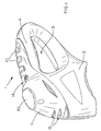
- Figure 1 is a perspective view of part of a housing of a power tool of a first embodiment of the present invention;
- Figure 2 is an exploded perspective view of the housing of the embodiment of Figure 1;
- Figures 3A to 3C show side cross-sectional views of three alternative forms of gel blister pack for use in the embodiment of Figures 1 and 2;
- Figure 4A is a side view of a handle assembly of a power tool of a second embodiment of the present invention;
- Figure 4B is a rear view of the handle assembly of Figure 4A;
- Figure 4C is a perspective view of the handle assembly of Figure 4A
- Figure 4D is a partial cross-sectional view showing the relation between the gel piece and the handle for the power tool shown in Figures 4A-C.
- Figure 4E is a side view showing an alternative embodiment of the power tool shown in Figure 4A.
- Referring to Figures 1 and 2, a
power tool 1 such as a drill or jigsaw comprises ahousing 2 defining an aperture 3 bounded on one side thereof by ahandle 4, thehousing 2 containing a motor (not shown) for actuating an output member such as a drill bit or jigsaw blade (not shown). - The
housing 2 is formed from a generally durable plastics material, as will be familiar to persons skilled in the art, and has arecessed portion 5 on a generally smooth upper surface of thehandle 4, therecessed portion 5 being provided with arecess 6 containing an actuating switch (not shown) for turning thetool 1 on and off. Thehousing 2 is provided with ventilation apertures 7 at one end of therecessed portion 5 to allow cooling of the interior of thehousing 2. - A
flexible sheet 8, of thermoplastic elastomeric material, such as a thin layer of polyurethane, having a coefficient of friction higher than that of the material from which thehousing 2 is made, is formed by means of a suitable method such as moulding. Thesheet 8 has a periphery shaped to fit inside the periphery ofrecessed portion 5 to cover all of therecessed portion 5 except that part in which the ventilation apertures 7 are provided, and theflexible sheet 8 is provided with a through-aperture 9 to allow access to the actuating switch inrecess 6. Theflexible sheet 8 is also provided with a series ofprotrusions 10, each of which defines a chamber between thesheet 8 and the upper surface of thehandle 4 of thehousing 2 when thesheet 8 is placed in position on the upper surface of the recessedportion 5. Each of the chambers underneath theprotrusions 10 accommodates a vibration damping gel contained in a blister pack 20 (Figures 3A to 3C). Alternatively, theflexible sheet 8 may be bonded to a backing sheet (not shown) to define the chambers containing the vibration damping gel. - A cover plate 11 of durable plastics material, such as the material from which the
housing 2 is constructed, has aninternal surface 12 corresponding generally to the external (i.e. upper) surface of theflexible sheet 8. The cover plate 11 is provided with a series offirst apertures 13 for allowing theprotrusions 10 of thesheet 8 to protrude therethrough when the plate 11 is mounted to thehandle 4 to secure theflexible sheet 8 in place, asecond aperture 14 co-operating with the aperture 9 to allow access to the actuating switch inrecess 6, and a series ofthird apertures 15 cooperating with the ventilation apertures 7 in thehousing 2. - Referring now to Figure 3A, a
gel blister pack 20 for use in the embodiment of Figures 1 and 2 is formed from a thin,flexible backing piece 21 of thermoplastic polyurethane film on which one ormore pieces 22 of a vibration damping gel formed from a semi-solid silicone rubber or polyurethane material are provided. Thepieces 22 of gel may be translucent and/or semi transparent and/or coloured, for reasons which will be explained in greater detail below. Thebacking layer 21 with thepieces 22 of gel are then covered by a generallytransparent layer 23 of thin, thermoplastic polyurethane film, which is pulled down tightly over thegel pieces 22 by means of a combination of heat and pressure, and then secured to thebacking piece 21 at theperiphery 24 of eachgel piece 22 to form discrete chambers encapsulating each gel piece by suitable welding techniques, such as heat staking and/or ultrasonic vibration, which will be familiar to persons skilled in the art. Alternatively, thegel material 22 can be poured or injected into a pre-formedtransparent sheet 23 and then covered bybacking piece 21 and welded. The upper surface of thebacking piece 21 may be printed with decorative or trade mark information which is visible through thetransparent layer 23 andgel 22. - Referring to Figure 3B, in which parts common to the embodiment of Figure 3A are denoted by like reference numerals but increased by 100 and will therefore not be described in greater detail herein, the
backing piece 121 of theblister pack 120 is provided with a series of raisedportions 125 which may be decorative matter and/or trade marks or raised lettering. The raisedportions 125 definerecesses 126, which may accommodate light emitting diodes which can be illuminated to provide a visual indication of an operating parameter of the tool incorporating theblister pack 120, for example to indicate whether the tool is switched on. - In the arrangement of Figure 3C, in which parts common to the embodiment of Figure 3B are denoted by like reference numerals but increased by 100, the raised
portions 225 definingrecesses 226 may be formed by aseparate layer 227, which is encapsulated along withgel material 222 bytransparent sheet 223 andbacking piece 221. - The operation of the
handle 4 of thetool 1 of Figures 1 to 3 will now be described. - When a user's hand (not shown) grips the
tool 1 when in use, the user's hand comes into contact with the cover plate 11 and theprotrusions 10 beneath which one ormore blister packs tool housing 2 are damped by the vibration damping gel underneathprotrusions 10, and the user's grip on the tool is maintained by contact between the user's hand and the high friction material of theflexible sheet 8. It can therefore be seen that by suitable choice of material of theflexible sheet 8, the frictional properties of thesheet 8 can be optimized, while the vibration damping properties of the gel-filledblister packs - Referring to Figures 4A to 4D, handle 404 of
power tool 401 of a second embodiment of the invention, for example, a drill, is defined by two halves 402A, 402B ofhousing 402.Drill 401 includes anupper motor housing 430 disposed abovehandle 404.Housing 430 may extend along or at a small angle to the horizontal direction, whilehandle 404 may extend along or at a small angle to the vertical direction. As shown, bothhousing 430 and handle 404 are slightly angled to the horizontal and vertical directions when the drill rests on a horizontal surface. The lower surface ofmotor housing 430 transitions intohandle 404 atfillet 404a. At its lower end handle 404 transitions intobattery receiving portion 435 at asecond fillet 404b.Battery 440 is slidably received in the receiving portion. Although the drill shown is a cordless drill receiving a removable battery which when inserted in the receiving portion forms the lower end of the drill, the invention could also be directed to a corded drill as well in which there is not a substantial part of the drill housing which is removable. - Three
gel pieces 422a-c protrude from the rear ofhandle 404 and extend throughcover plate 411, which may be formed in one or two pieces. Bothgel pieces 422a-c andcover plate 411 may have the same structure as the cover plate and gel pieces described with respect to the embodiment of Figures 1-3.Gel pieces 422a-c encompass the rear ofhandle 404 and extend partially around both sides ofhandle 404 and preferably terminate rearwardly of the center axis Y-Y ofhandle 404, which extends at a slight angle to the vertical. Preferably,upper gel piece 422a is positioned relatively high onhandle 404, encompassingupper fillet 404a, oppositedepressible trigger 429 which is disposed through the front ofhandle 404.Upper gel piece 422a extends downwardly for substantially the same distance astrigger 429 to provide the maximum cushioning benefit when the user actuatestrigger 429. - In a preferred embodiment, the overall gripping region of the tool extends generally from
upper fillet 404a towardslower fillet 404b in a range of 80-100mm as measured in the vertical direction. Preferablylower gel piece 422c terminates above and adjacentlower fillet 404b.Upper gel piece 422a may extend in the vertical direction ofhandle 404 for 36 mm. At its maximum,upper gel piece 422a extends along each side ofhandle 404 in the direction which is transverse to the centerline Y-Y to a location which is 11 mm rearward of centerline Y-Y. The distance in the vertical direction betweenupper gel piece 422a andmiddle gel piece 422b may be 8 mm. The dimension of the middle andlower gel pieces handle 404 in the direction which is transverse to the centerline Y-Y to a location which is 13 mm rearward of the centerline Y-Y. The distance in the vertical direction betweenmiddle gel piece 422b andlower gel piece 422c may be 7 mm. The distance in the vertical direction betweenlower gel piece 422c andlower fillet 404b may be 15 mm. The thickness ofgel pieces 422a-c may be between 5-10 mm. -
Cover plate 411 may be formed as one saddle-shaped piece which extends about the rear and partially along each side ofhandle 404. Alternatively coverplate 411 may be formed as two pieces, with one piece disposed on each handle half. As measured in the vertical direction,cover plate 411 may extend from a location which is 6 mm aboveupper gel piece 422a to a location which is 8 mm belowlower gel piece 422c. The openings incover plate 411 have dimensions corresponding to those ofgel pieces 422a-c. As shown, at an upperlocation cover plate 411 may extend forwardly of centerline Y-Y for 12 mm at its maximum. At a location which is about 32 mm below the upper edge ofcover plate 411,cover plate 411 narrows such that it only extends to a location which is 4 mm to the rear of centerline Y-Y. As shown in Figure 4D,gel piece 422c may project outwardly fromcover plate 411 by 3 mm.Gel pieces cover plate 411 by 3 mm. - Figure 4E shows an alternative to the embodiment shown in Figures 4A-4D. In Figure 4E, only a single gel piece 422' is disposed on handle 404'. Gel piece 422' may have a saddle shape and wrap around the rear of handle 404', and extend forwardly on both side of handle 404', terminating to the rear of centerline Y-Y. Alternatively, two gel pieces 422' which jointly form a saddle shape and wrap around the rear of handle 404' may be used. With respect to the portion of handle 404,404' covered by the gel piece(s), the overall dimensions of gel piece 422' are similar to those of the three
gel pieces 422a-c of Figures 4A-C. However, in the present embodiment, gel piece 422' also occupies the regions of handle 404' between each ofgel pieces 422a-c. Similarly, the overall dimensions of cover plate 411' is similar to the overall dimensions ofcover plate 411. - It will be appreciated skilled in the art that the above embodiments have been described by way of example only, and not in any limitative sense, and that various alterations and modifications are possible without departure from the scope of the invention as defined by the appended claims.
Claims (6)
- A drill comprising:a motor housing;a handle extending downwardly from said motor housing, said handle having a front surface, a rear surface and side surfaces;a chamber enclosing a gel material disposed on said handle, said chamber disposed about the rear surface of said handle and extending forwardly along both said side surfaces;and a cover plate made of a material which is relatively hard as compared to said chamber, said cover plate disposed on said handle and including an aperture through which said chamber protrudes.
- The drill recited in claim 1 further comprising a trigger switch extending through said front surface, said chamber disposed on said handle at a location opposite said trigger switch.
- The drill recited in claim 1, an upper transition defined between said motor housing and said handle, said chamber disposed so as to encompass said transition.
- The drill recited in claim 3, said drill comprising a lower housing structure disposed below said handle, a lower transition defined between said handle and said lower housing structure, said chamber terminating at a location adjacent said lower transition.
- The drill recited in claim 4, said lower housing structure comprising a battery receiving housing.
- The drill recited in claim 1, said handle having a longitudinal center axis, said chamber extending along said side surfaces so as to terminate rearwardly of said center axis.
Applications Claiming Priority (2)
| Application Number | Priority Date | Filing Date | Title |
|---|---|---|---|
| US10/849,709 US7930572B2 (en) | 2003-12-24 | 2004-05-19 | Method and apparatus for reducing memory current leakage a mobile device |
| EP05009808A EP1602453B1 (en) | 2004-05-20 | 2005-05-05 | Handle assembly for tool |
Related Parent Applications (1)
| Application Number | Title | Priority Date | Filing Date |
|---|---|---|---|
| EP05009808A Division EP1602453B1 (en) | 2004-05-19 | 2005-05-05 | Handle assembly for tool |
Publications (2)
| Publication Number | Publication Date |
|---|---|
| EP1832396A1 true EP1832396A1 (en) | 2007-09-12 |
| EP1832396B1 EP1832396B1 (en) | 2008-07-09 |
Family
ID=39616559
Family Applications (1)
| Application Number | Title | Priority Date | Filing Date |
|---|---|---|---|
| EP07111374A Expired - Lifetime EP1832396B1 (en) | 2004-05-19 | 2005-05-05 | Handle assembly for tool |
Country Status (3)
| Country | Link |
|---|---|
| EP (1) | EP1832396B1 (en) |
| AT (1) | ATE400409T1 (en) |
| DE (1) | DE602005008108D1 (en) |
Cited By (1)
| Publication number | Priority date | Publication date | Assignee | Title |
|---|---|---|---|---|
| US12257671B2 (en) | 2022-06-16 | 2025-03-25 | Milwaukee Electric Tool Corporation | Power tool with battery vibration mitigation |
Citations (2)
| Publication number | Priority date | Publication date | Assignee | Title |
|---|---|---|---|---|
| US20030159251A1 (en) * | 2002-02-28 | 2003-08-28 | Robinson Josh M. | Hand pressure abatement apparatus for use with a power tool |
| US20040078936A1 (en) * | 2002-10-28 | 2004-04-29 | Andrew Walker | Handle assembly for tool |
-
2005
- 2005-05-05 AT AT07111374T patent/ATE400409T1/en not_active IP Right Cessation
- 2005-05-05 DE DE602005008108T patent/DE602005008108D1/en not_active Expired - Lifetime
- 2005-05-05 EP EP07111374A patent/EP1832396B1/en not_active Expired - Lifetime
Patent Citations (2)
| Publication number | Priority date | Publication date | Assignee | Title |
|---|---|---|---|---|
| US20030159251A1 (en) * | 2002-02-28 | 2003-08-28 | Robinson Josh M. | Hand pressure abatement apparatus for use with a power tool |
| US20040078936A1 (en) * | 2002-10-28 | 2004-04-29 | Andrew Walker | Handle assembly for tool |
Cited By (1)
| Publication number | Priority date | Publication date | Assignee | Title |
|---|---|---|---|---|
| US12257671B2 (en) | 2022-06-16 | 2025-03-25 | Milwaukee Electric Tool Corporation | Power tool with battery vibration mitigation |
Also Published As
| Publication number | Publication date |
|---|---|
| EP1832396B1 (en) | 2008-07-09 |
| ATE400409T1 (en) | 2008-07-15 |
| DE602005008108D1 (en) | 2008-08-21 |
Similar Documents
| Publication | Publication Date | Title |
|---|---|---|
| EP1419856B1 (en) | Handle assembly for tool | |
| EP1602453B1 (en) | Handle assembly for tool | |
| EP2027975B1 (en) | Power tool | |
| CN101687318B (en) | Electric tool | |
| US20050155778A1 (en) | Power tool having outer protection layer | |
| US20060220612A1 (en) | Modular panel for a power tool | |
| EP2075095B1 (en) | Power tool | |
| US7201643B2 (en) | Handle assembly for tool | |
| EP1415769A1 (en) | Handle assembly for tool | |
| JP5413039B2 (en) | Portable tools | |
| US20060003680A1 (en) | Power tool | |
| EP1832396B1 (en) | Handle assembly for tool | |
| JP4529550B2 (en) | Portable power tools | |
| AU2004200441B2 (en) | Handle assembly for tool | |
| JP2009113131A (en) | Tool with soft touch elastic layer | |
| JP2008155300A (en) | Portable power tool | |
| CA2507475A1 (en) | Modular panel for a power tool |
Legal Events
| Date | Code | Title | Description |
|---|---|---|---|
| PUAI | Public reference made under article 153(3) epc to a published international application that has entered the european phase |
Free format text: ORIGINAL CODE: 0009012 |
|
| 17P | Request for examination filed |
Effective date: 20070629 |
|
| AC | Divisional application: reference to earlier application |
Ref document number: 1602453 Country of ref document: EP Kind code of ref document: P |
|
| AK | Designated contracting states |
Kind code of ref document: A1 Designated state(s): AT BE BG CH CY CZ DE DK EE ES FI FR GB GR HU IE IS IT LI LT LU LV MC MT NL PL PT RO SE SI SK TR |
|
| AX | Request for extension of the european patent |
Extension state: AL BA HR MK YU |
|
| RAP1 | Party data changed (applicant data changed or rights of an application transferred) |
Owner name: BLACK & DECKER, INC. |
|
| GRAP | Despatch of communication of intention to grant a patent |
Free format text: ORIGINAL CODE: EPIDOSNIGR1 |
|
| GRAS | Grant fee paid |
Free format text: ORIGINAL CODE: EPIDOSNIGR3 |
|
| AKX | Designation fees paid |
Designated state(s): AT BE BG CH CY CZ DE DK EE ES FI FR GB GR HU IE IS IT LI LT LU MC NL PL PT RO SE SI SK TR |
|
| GRAA | (expected) grant |
Free format text: ORIGINAL CODE: 0009210 |
|
| AC | Divisional application: reference to earlier application |
Ref document number: 1602453 Country of ref document: EP Kind code of ref document: P |
|
| AK | Designated contracting states |
Kind code of ref document: B1 Designated state(s): AT BE BG CH CY CZ DE DK EE ES FI FR GB GR HU IE IS IT LI LT LU MC NL PL PT RO SE SI SK TR |
|
| REG | Reference to a national code |
Ref country code: GB Ref legal event code: FG4D |
|
| REG | Reference to a national code |
Ref country code: CH Ref legal event code: EP |
|
| REF | Corresponds to: |
Ref document number: 602005008108 Country of ref document: DE Date of ref document: 20080821 Kind code of ref document: P |
|
| REG | Reference to a national code |
Ref country code: IE Ref legal event code: FG4D |
|
| NLV1 | Nl: lapsed or annulled due to failure to fulfill the requirements of art. 29p and 29m of the patents act | ||
| PG25 | Lapsed in a contracting state [announced via postgrant information from national office to epo] |
Ref country code: NL Free format text: LAPSE BECAUSE OF FAILURE TO SUBMIT A TRANSLATION OF THE DESCRIPTION OR TO PAY THE FEE WITHIN THE PRESCRIBED TIME-LIMIT Effective date: 20080709 Ref country code: LT Free format text: LAPSE BECAUSE OF FAILURE TO SUBMIT A TRANSLATION OF THE DESCRIPTION OR TO PAY THE FEE WITHIN THE PRESCRIBED TIME-LIMIT Effective date: 20080709 Ref country code: IS Free format text: LAPSE BECAUSE OF FAILURE TO SUBMIT A TRANSLATION OF THE DESCRIPTION OR TO PAY THE FEE WITHIN THE PRESCRIBED TIME-LIMIT Effective date: 20081109 |
|
| PG25 | Lapsed in a contracting state [announced via postgrant information from national office to epo] |
Ref country code: FI Free format text: LAPSE BECAUSE OF FAILURE TO SUBMIT A TRANSLATION OF THE DESCRIPTION OR TO PAY THE FEE WITHIN THE PRESCRIBED TIME-LIMIT Effective date: 20080709 Ref country code: ES Free format text: LAPSE BECAUSE OF FAILURE TO SUBMIT A TRANSLATION OF THE DESCRIPTION OR TO PAY THE FEE WITHIN THE PRESCRIBED TIME-LIMIT Effective date: 20081020 Ref country code: SI Free format text: LAPSE BECAUSE OF FAILURE TO SUBMIT A TRANSLATION OF THE DESCRIPTION OR TO PAY THE FEE WITHIN THE PRESCRIBED TIME-LIMIT Effective date: 20080709 Ref country code: BG Free format text: LAPSE BECAUSE OF FAILURE TO SUBMIT A TRANSLATION OF THE DESCRIPTION OR TO PAY THE FEE WITHIN THE PRESCRIBED TIME-LIMIT Effective date: 20081009 Ref country code: PT Free format text: LAPSE BECAUSE OF FAILURE TO SUBMIT A TRANSLATION OF THE DESCRIPTION OR TO PAY THE FEE WITHIN THE PRESCRIBED TIME-LIMIT Effective date: 20081209 Ref country code: AT Free format text: LAPSE BECAUSE OF FAILURE TO SUBMIT A TRANSLATION OF THE DESCRIPTION OR TO PAY THE FEE WITHIN THE PRESCRIBED TIME-LIMIT Effective date: 20080709 |
|
| PG25 | Lapsed in a contracting state [announced via postgrant information from national office to epo] |
Ref country code: BE Free format text: LAPSE BECAUSE OF FAILURE TO SUBMIT A TRANSLATION OF THE DESCRIPTION OR TO PAY THE FEE WITHIN THE PRESCRIBED TIME-LIMIT Effective date: 20080709 |
|
| PG25 | Lapsed in a contracting state [announced via postgrant information from national office to epo] |
Ref country code: DK Free format text: LAPSE BECAUSE OF FAILURE TO SUBMIT A TRANSLATION OF THE DESCRIPTION OR TO PAY THE FEE WITHIN THE PRESCRIBED TIME-LIMIT Effective date: 20080709 Ref country code: EE Free format text: LAPSE BECAUSE OF FAILURE TO SUBMIT A TRANSLATION OF THE DESCRIPTION OR TO PAY THE FEE WITHIN THE PRESCRIBED TIME-LIMIT Effective date: 20080709 |
|
| PLBE | No opposition filed within time limit |
Free format text: ORIGINAL CODE: 0009261 |
|
| STAA | Information on the status of an ep patent application or granted ep patent |
Free format text: STATUS: NO OPPOSITION FILED WITHIN TIME LIMIT |
|
| PG25 | Lapsed in a contracting state [announced via postgrant information from national office to epo] |
Ref country code: CZ Free format text: LAPSE BECAUSE OF FAILURE TO SUBMIT A TRANSLATION OF THE DESCRIPTION OR TO PAY THE FEE WITHIN THE PRESCRIBED TIME-LIMIT Effective date: 20080709 Ref country code: SK Free format text: LAPSE BECAUSE OF FAILURE TO SUBMIT A TRANSLATION OF THE DESCRIPTION OR TO PAY THE FEE WITHIN THE PRESCRIBED TIME-LIMIT Effective date: 20080709 Ref country code: RO Free format text: LAPSE BECAUSE OF FAILURE TO SUBMIT A TRANSLATION OF THE DESCRIPTION OR TO PAY THE FEE WITHIN THE PRESCRIBED TIME-LIMIT Effective date: 20080709 |
|
| 26N | No opposition filed |
Effective date: 20090414 |
|
| PG25 | Lapsed in a contracting state [announced via postgrant information from national office to epo] |
Ref country code: IT Free format text: LAPSE BECAUSE OF FAILURE TO SUBMIT A TRANSLATION OF THE DESCRIPTION OR TO PAY THE FEE WITHIN THE PRESCRIBED TIME-LIMIT Effective date: 20080709 |
|
| PG25 | Lapsed in a contracting state [announced via postgrant information from national office to epo] |
Ref country code: MC Free format text: LAPSE BECAUSE OF NON-PAYMENT OF DUE FEES Effective date: 20090531 |
|
| REG | Reference to a national code |
Ref country code: CH Ref legal event code: PL |
|
| PG25 | Lapsed in a contracting state [announced via postgrant information from national office to epo] |
Ref country code: SE Free format text: LAPSE BECAUSE OF FAILURE TO SUBMIT A TRANSLATION OF THE DESCRIPTION OR TO PAY THE FEE WITHIN THE PRESCRIBED TIME-LIMIT Effective date: 20081009 Ref country code: LI Free format text: LAPSE BECAUSE OF NON-PAYMENT OF DUE FEES Effective date: 20090531 Ref country code: CH Free format text: LAPSE BECAUSE OF NON-PAYMENT OF DUE FEES Effective date: 20090531 |
|
| PG25 | Lapsed in a contracting state [announced via postgrant information from national office to epo] |
Ref country code: IE Free format text: LAPSE BECAUSE OF NON-PAYMENT OF DUE FEES Effective date: 20090505 |
|
| PG25 | Lapsed in a contracting state [announced via postgrant information from national office to epo] |
Ref country code: PL Free format text: LAPSE BECAUSE OF FAILURE TO SUBMIT A TRANSLATION OF THE DESCRIPTION OR TO PAY THE FEE WITHIN THE PRESCRIBED TIME-LIMIT Effective date: 20080709 |
|
| PG25 | Lapsed in a contracting state [announced via postgrant information from national office to epo] |
Ref country code: GR Free format text: LAPSE BECAUSE OF FAILURE TO SUBMIT A TRANSLATION OF THE DESCRIPTION OR TO PAY THE FEE WITHIN THE PRESCRIBED TIME-LIMIT Effective date: 20081010 |
|
| PG25 | Lapsed in a contracting state [announced via postgrant information from national office to epo] |
Ref country code: LU Free format text: LAPSE BECAUSE OF NON-PAYMENT OF DUE FEES Effective date: 20090505 |
|
| PG25 | Lapsed in a contracting state [announced via postgrant information from national office to epo] |
Ref country code: HU Free format text: LAPSE BECAUSE OF FAILURE TO SUBMIT A TRANSLATION OF THE DESCRIPTION OR TO PAY THE FEE WITHIN THE PRESCRIBED TIME-LIMIT Effective date: 20090110 |
|
| PG25 | Lapsed in a contracting state [announced via postgrant information from national office to epo] |
Ref country code: TR Free format text: LAPSE BECAUSE OF FAILURE TO SUBMIT A TRANSLATION OF THE DESCRIPTION OR TO PAY THE FEE WITHIN THE PRESCRIBED TIME-LIMIT Effective date: 20080709 |
|
| PG25 | Lapsed in a contracting state [announced via postgrant information from national office to epo] |
Ref country code: CY Free format text: LAPSE BECAUSE OF FAILURE TO SUBMIT A TRANSLATION OF THE DESCRIPTION OR TO PAY THE FEE WITHIN THE PRESCRIBED TIME-LIMIT Effective date: 20080709 |
|
| REG | Reference to a national code |
Ref country code: FR Ref legal event code: PLFP Year of fee payment: 12 |
|
| REG | Reference to a national code |
Ref country code: FR Ref legal event code: PLFP Year of fee payment: 13 |
|
| REG | Reference to a national code |
Ref country code: FR Ref legal event code: PLFP Year of fee payment: 14 |
|
| PGFP | Annual fee paid to national office [announced via postgrant information from national office to epo] |
Ref country code: GB Payment date: 20180329 Year of fee payment: 14 |
|
| PGFP | Annual fee paid to national office [announced via postgrant information from national office to epo] |
Ref country code: DE Payment date: 20180424 Year of fee payment: 14 |
|
| PGFP | Annual fee paid to national office [announced via postgrant information from national office to epo] |
Ref country code: FR Payment date: 20180411 Year of fee payment: 14 |
|
| REG | Reference to a national code |
Ref country code: DE Ref legal event code: R119 Ref document number: 602005008108 Country of ref document: DE |
|
| GBPC | Gb: european patent ceased through non-payment of renewal fee |
Effective date: 20190505 |
|
| PG25 | Lapsed in a contracting state [announced via postgrant information from national office to epo] |
Ref country code: GB Free format text: LAPSE BECAUSE OF NON-PAYMENT OF DUE FEES Effective date: 20190505 Ref country code: DE Free format text: LAPSE BECAUSE OF NON-PAYMENT OF DUE FEES Effective date: 20191203 |
|
| PG25 | Lapsed in a contracting state [announced via postgrant information from national office to epo] |
Ref country code: FR Free format text: LAPSE BECAUSE OF NON-PAYMENT OF DUE FEES Effective date: 20190531 |