EP1831936B1 - Piezoelectric bimorph actuator and method of manufacturing thereof - Google Patents
Piezoelectric bimorph actuator and method of manufacturing thereof Download PDFInfo
- Publication number
- EP1831936B1 EP1831936B1 EP05854138.4A EP05854138A EP1831936B1 EP 1831936 B1 EP1831936 B1 EP 1831936B1 EP 05854138 A EP05854138 A EP 05854138A EP 1831936 B1 EP1831936 B1 EP 1831936B1
- Authority
- EP
- European Patent Office
- Prior art keywords
- bimorph
- actuator
- piezoelectric bimorph
- packaging
- carrier
- Prior art date
- Legal status (The legal status is an assumption and is not a legal conclusion. Google has not performed a legal analysis and makes no representation as to the accuracy of the status listed.)
- Expired - Lifetime
Links
Images


Classifications
-
- H—ELECTRICITY
- H10—SEMICONDUCTOR DEVICES; ELECTRIC SOLID-STATE DEVICES NOT OTHERWISE PROVIDED FOR
- H10N—ELECTRIC SOLID-STATE DEVICES NOT OTHERWISE PROVIDED FOR
- H10N30/00—Piezoelectric or electrostrictive devices
- H10N30/80—Constructional details
- H10N30/88—Mounts; Supports; Enclosures; Casings
-
- H—ELECTRICITY
- H10—SEMICONDUCTOR DEVICES; ELECTRIC SOLID-STATE DEVICES NOT OTHERWISE PROVIDED FOR
- H10N—ELECTRIC SOLID-STATE DEVICES NOT OTHERWISE PROVIDED FOR
- H10N30/00—Piezoelectric or electrostrictive devices
- H10N30/20—Piezoelectric or electrostrictive devices with electrical input and mechanical output, e.g. functioning as actuators or vibrators
- H10N30/204—Piezoelectric or electrostrictive devices with electrical input and mechanical output, e.g. functioning as actuators or vibrators using bending displacement, e.g. unimorph, bimorph or multimorph cantilever or membrane benders
Definitions
- the present disclosure relates to piezoelectric bimorph actuators encased in an insulating shell to ensure that the actuator is substantially moisture impervious.
- Bimorphs are piezoelectric elements which change their shape under application of electrical energy. Bimorphs are widely used in a variety of actuators, such as in shutter mechanisms of cameras, head assemblies of hard drive disks, etc. In particular, bimorph type actuators are also used in gas transducers. Gas transducers are utilized in a variety of industries, such as pipeline, chemical, distillery, food processing, petrochemical, pharmaceutical and other industries where precise control of various valves and other equipment is desired. Gas transducers operate by controlling gas flow and/or pressure, which in turn actuates other equipment (e.g., valves, louvers, etc.). However, use of piezoelectric bimorph actuators where the gas stream may contain a significant amount of moisture can be problematic.
- bimorph actuators develop electrical problems and in certain situations stop functioning altogether (e.g., arcing across energized regions of the bimorph). More particularly, electrical malfunction is especially dangerous when bimorph actuators are used in combustible atmosphere (e.g., natural gas)-electrical arcing may result in ignition.
- combustible atmosphere e.g., natural gas
- the present disclosure provides for an actuator having a piezoelectric bimorph disposed within substantially moisture impervious and electrically insulating packaging.
- the bimorph is disposed within a cavity of the packaging and provides a predetermined clearance around the bimorph allowing the bimorph to move freely therein.
- transducer is disdosed as specified in claim 9.
- the present disclosure provides for a piezoelectric bimorph actuator in a gas transducer. More specifically, the bimorph actuator according to the present invention includes a free-floating packaged bimorph which is not affected by the movement of its packaging. Moreover, the packaging renders the actuator substantially moisture impervious and electrically insulated.
- the bimorph actuator includes a piezoelectric bimorph disposed within a packaging.
- the packaging includes a carrier having first and second surfaces and first and second cover films disposed on the first and second surfaces respectively. More specifically, the bimorph is disposed within an aperture of the carrier.
- the actuator further includes first and second adhesive layers disposed on the first and second surfaces of the carrier respectively so that the adhesive is not in contact with the bimorph.
- First and second flex circuits are disposed within the first and second adhesive layers and are configured to conduct electrical energy to the bimorph.
- the actuator also includes first and second cover films disposed on top of the first and second adhesive layers and the first and second flex circuits thereby encapsulating the bimorph.
- the packaging (e.g., the carrier and/or the cover films) forms a cavity around the bimorph of a predetermined size which provides for sufficient clearance around the bimorph.
- the clearance allows the bimorph not to be constricted by the packaging during extreme temperatures (e.g., thermal expansion of the carrier and/or cover films).
- Figure 1 shows a fully-assembled piezoelectric bimorph actuator 2 having a packaging 3 which includes a first cover film 4 and a second cover film 8 as shown in Figure 2 .
- the packaging 3 includes a plurality of holes 5 which are used to attach the actuator 2 to a gas transducer and/or during assembly of the packaging 3 (e.g., to attach the components of the packaging 3 together).
- the holes 5 are optional and it is envisioned that other mechanisms may be used to secure the actuator 2 to the transducer or other devices. It is also envisioned that the holes may be used for pressure equalization and/or for gas bypass.
- the actuator 2 also includes flex circuits 7, 9 as shown in Figure 2 .
- the actuator 2 activates through the activation of the bimorph 16. More specifically, the flex circuits 7, 9 are in contact with the bimorph 16 and supply electrical energy thereto. Once the bimorph 16 receives electricity, the bimorph 16 is activated and affects the movement of the packaging 3.
- the flex circuits 7, 9 are sufficiently flexible and can maintain contact with the bimorph 16 during activation.
- the flex circuits 7, 9 may be die cut from copper foil of about 0.05mm thickness.
- a piezoelectric bimorph 16 is disposed within the packaging 3, which includes a carrier 14 having first and second surfaces 11, 13, first and second adhesive layers 10, 12 disposed on the first and second surfaces 11, 13, and the aperture 15 is of a predetermined size which provides for sufficient clearance around the bimorph 16, and first and second the cover films 4, 8 are disposed on the first and second adhesive layers 10, 12 respectively.
- the bimorph 16 may be formed from a variety of piezoelectric materials, such as lead zirconate titanate (PZT), quartz, barium titanate, and the like. It is also envisioned that magnetostrictives and electrostrictives may be suitable.
- the bimorph 16 is disposed within an aperture 15 of the carrier 14 as shown in Figure 3 .
- the aperture 15 is of substantially the same shape as the bimorph 16 (e.g., circular) but the aperture 15 is sufficiently larger than the bimorph 16 to provide for a clearance "C" between the bimorph 16 and the carrier 14.
- the clearance "C” provides greater freedom of motion for the bimorph 16 (e.g., float freely) within the carrier 14 and the packaging 3 since the bimorph 16 is not secured and/or attached to any of the components (e.g., carrier 14, the adhesive layers 10, 12, and the cover films 4, 8) of the packaging 3.
- the carrier 14 and the first and second cover films 4, 8 are formed from a suitable polymer (e.g., polymide laminate, polyester, Transilwrap(TM) corona treated 92 gauge Mylar, etc.) and are machined and/or stamped to produce the desired shape.
- the thickness of the carrier 14 depends on the thickness of the bimorph 16 and is from about 0.1mm to about 2.5mm.
- the thickness of the first and second cover films 4, 8 is from about 0.01mm to about 0.12mm.
- the carrier 14 and the first and second cover films 4, 8 are machined and/or stamped to have a circular shape to encapsulate the bimorph 16 which has a circular shape.
- holes are created (e.g., drilled, stamped, etc.), through which attachment mechanisms (e.g., bolts) attach the actuator 2 to the intended device. The drilling step may be performed once the actuator 2 is fully assembled.
- the carrier 14 and the first and second cover films 4, 8 can be formed through a plurality of processes (e.g., curtain extrusion to a film form, injection molding, casting, etc.).
- the holes 5 may be of different diameter to accommodate attachment mechanisms (e.g., bolts, rivets, etc.) of various sizes. This is particularly useful if the components of the packaging 3 (e.g., the carrier 14, the first and second cover films 4, 8, etc.) are attached to each other using various attachment mechanisms (e.g., bolts, rivets, etc.).
- attachment mechanisms e.g., bolts, rivets, etc.
- the carrier 14 is machined and/or stamped to create the aperture 15 of a predetermined size which provides for sufficient clearance "C" around the bimorph 16.
- the first cover film 4 is selectively attached to the carrier 14 using the first adhesive layer 10, to avoid attachment to the bimorph 16.
- the flex circuit 7 is adjacent to the bimorph 16 so that the flex circuit 7 is in contact with the bimorph 16. The flex circuit 7 is held between the first cover film 4 and the adhesive layers 10.
- the bimorph 16 is inserted within the assembled portion of the packaging 3, namely the carrier 14 and the first cover film 4 attached together with the flex circuit 7 disposed between the cover film 4 and the adhesive layer 10.
- the flex circuits 7, 9 contact the bimorph 16 by way of the force developed on the cover films 4, 8 respectively.
- the second cover film 8 is selectively attached to the carrier 14, also to avoid attachment to the bimorph 16, at the second surface 13 via the second adhesive layer 12.
- the flex circuit 9 is disposed between the second surface 13 and the second cover film 8 and is in contact with the bimorph 16.
- the assembly of the actuator 2 may be accomplished by attaching the first and second cover films 4, 8 in any order (e.g., attaching the second cover film 8 initially, inserting the bimorph 16 into the resulting portion, thereafter attaching the first cover film 4) and on any of the surfaces 11, 13.
- the adhesive layers 10, 12 may be tacked to the carrier 14
- the adhesive layers 10, 12 may be formed from a thermal active adhesive or another type, such as thermally activated double sided laminating films (e.g., Transilwrap(TM) PAM K 3 1/1/1).
- the first and second adhesive layers 10, 12 have a substantially similar shape as the first and second surfaces 11, 13 of the carrier 14 to ensure that the adhesive layers 10, 12 selectively attach the carrier 14 to the first and second cover films 4, 8. Namely, that the carrier 14 and the first and second cover films 4, 8 are bonded to each other and not to the bimorph 16. This allows the bimorph 16 to be enclosed within the cavity 17 ( FIG. 4 ).
- the bimorph 16 is free to flex when electrically activated through the flex circuits 7, 9 and thereby effect (e.g., through flexing activate) the packaging 3, while packaging 3 cannot effect the movement of the bimorph 16 (e.g., through expansion or contraction affected by extreme temperatures).
- the first and second cover films 4, 8 are not immediately bonded to the carrier 14 since the adhesive layers 10, 12 are thermally activated. Therefore, the cover films 4, 8 are temporarily attached to the carrier 14 and the adhesive layers 10, 12 (e.g., tacked). Thereafter, the assembled actuator is processed through a laminator operating at a temperature from about 80 degrees Celsius to about 200 degrees Celsius and at a pressure from about 35kPa to about 1.4 MPa, ensuring that the temperature does not drop below the operational temperature of the bimorph 16 and does not exceed the Curie point while the pressure is not excessive and does not crack the bimorph 16.
- the adhesive layers 10, 12 secure the flex circuits 7, 9 and the first and second cover films 4, 8 to the carrier 14, enclosing the bimorph 16 therein.
- the actuator 2 may be cooled and then machined to remove excess peripheral material.
- holes 5 may be drilled. The machining may be performed by a carbide end mill, rotating to produce at least 4.6 square metres per minute (50 square feet per minute).
- the packaging 3 may be assembled using a variety of other attachment mechanisms, such as for example rivets and/or bolts.
- the carrier 14 and the first and second cover films 4, 8 are selectively attached using attachment mechanisms so that the bimorph 16 is encapsulated by the packaging 3 within the cavity 17 without being attached to the carrier 14 and/or the first and second cover films 4, 8 as shown in Figure 4 .
- the carrier 14 may include a relief 21 cut therein to support the bimorph 16 (not shown).
- the relief 21 has the same shape as the bimorph 16, in the present embodiment, it is circular, in order to allow for mispositioning of the bimorph 16.
- the relief 21 is separated from the carrier 14 by the clearance "C" which allows the bimorph 16 not to be in contact with the side portions of the carrier 14.
- a rectangular bimorph 30 is inserted into a rectangular carrier 22.
- the carrier 22 and the first and second cover films (not shown), which are also rectangular, are assembled in substantially the same manner to form a rectangular actuator 20.
- the first and second cover films are selectively attached to the carrier 22 using the first and second adhesive layers (not shown) which bond the first and second cover films to the first and second surfaces 32, 33 of the carrier 22, respectively.
- the adhesive layers also attach flex circuits 26, 28 to the actuator 20 and are connected to the bimorph 30.
- holes 24 are drilled through the actuator 20 allowing the actuator 20 to be mounted within a device or for other attachment mechanisms to be used to assemble the actuator 20.
Landscapes
- General Electrical Machinery Utilizing Piezoelectricity, Electrostriction Or Magnetostriction (AREA)
Description
- The present disclosure relates to piezoelectric bimorph actuators encased in an insulating shell to ensure that the actuator is substantially moisture impervious.
- Bimorphs are piezoelectric elements which change their shape under application of electrical energy. Bimorphs are widely used in a variety of actuators, such as in shutter mechanisms of cameras, head assemblies of hard drive disks, etc. In particular, bimorph type actuators are also used in gas transducers. Gas transducers are utilized in a variety of industries, such as pipeline, chemical, distillery, food processing, petrochemical, pharmaceutical and other industries where precise control of various valves and other equipment is desired. Gas transducers operate by controlling gas flow and/or pressure, which in turn actuates other equipment (e.g., valves, louvers, etc.). However, use of piezoelectric bimorph actuators where the gas stream may contain a significant amount of moisture can be problematic. High moisture content degrades the bimorph actuators, wherein the bimorphs develop electrical problems and in certain situations stop functioning altogether (e.g., arcing across energized regions of the bimorph). More particularly, electrical malfunction is especially dangerous when bimorph actuators are used in combustible atmosphere (e.g., natural gas)-electrical arcing may result in ignition.
- Attempts have been made to create moisture-proof piezoelectric bimorph actuators which are insulated to prevent arcing. However these attempts generally involved actuators having bonded monolithic packaging requiring that the actuator deform the entire packaging to operate. Furthermore, in gas transducers, operating temperatures range from about -40 to about 70 degrees Celsius. The extreme temperatures expand and contract the packaging thereby constricting movement of the bimorph as well. This imparts a significant strain upon the actuator rendering the device inoperable.
- Therefore, there is a need for a free-floating piezoelectric bimorph actuator which is substantially moisture impervious and electrically insulated as well as protected from extraneous strain stemming from deleterious effects of a monolithically formed bimorph package.
- The present disclosure provides for an actuator having a piezoelectric bimorph disposed within substantially moisture impervious and electrically insulating packaging. The bimorph is disposed within a cavity of the packaging and provides a predetermined clearance around the bimorph allowing the bimorph to move freely therein.
- It is known from
US 4857887 to provide a laminated keyboard that employs piezoelectric elements to generate an electrical signal in response to the application of finger pressure to one of the keys. - is an According to the invention there is provided an actuator as specified in claim 1.
- According to another aspect of the disclosure a transducer is disdosed as specified in
claim 9. - According to a further aspect of the disclosure a method for manufacturing an actuator is disclosed as specified in claim 18.
- The above and other aspects, features, and advantages of the present disclosure will become more apparent in light of the following detailed description when taken in conjunction with the accompanying drawings in which:
-
Figure 1 is an isometric view of a piezoelectric bimorph actuator according to the present disclosure; -
Figure 2 is an exploded isometric view of the piezoelectric bimorph actuator according to the present disclosure; -
Figure 3 is an isometric view of the piezoelectric bimorph within a carrier according to the present disclosure; -
Figure 4 is a cross-sectional view of the piezoelectric bimorph actuator according to the present disclosure; -
Figure 5 is an isometric view of the carrier according to the present disclosure; and -
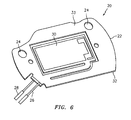
Figure 6 is an isometric view of an alternate embodiment of a piezoelectric bimorph within a carrier according to the present disclosure. - Specific embodiments of the present disclosure will be described herein below with reference to the accompanying drawings. In the following description, well-known functions or constructions are not described in detail to avoid obscuring the present disclosure in unnecessary detail.
- It is desirable for actuators used in gas transducers to have minimal stress imparted thereon. The actuator must be free to move through its travel to control the stream of gas passing through the gas transducer. Therefore, the present disclosure provides for a piezoelectric bimorph actuator in a gas transducer. More specifically, the bimorph actuator according to the present invention includes a free-floating packaged bimorph which is not affected by the movement of its packaging. Moreover, the packaging renders the actuator substantially moisture impervious and electrically insulated.
- The bimorph actuator includes a piezoelectric bimorph disposed within a packaging. The packaging includes a carrier having first and second surfaces and first and second cover films disposed on the first and second surfaces respectively. More specifically, the bimorph is disposed within an aperture of the carrier. The actuator further includes first and second adhesive layers disposed on the first and second surfaces of the carrier respectively so that the adhesive is not in contact with the bimorph. First and second flex circuits are disposed within the first and second adhesive layers and are configured to conduct electrical energy to the bimorph. The actuator also includes first and second cover films disposed on top of the first and second adhesive layers and the first and second flex circuits thereby encapsulating the bimorph. The packaging (e.g., the carrier and/or the cover films) forms a cavity around the bimorph of a predetermined size which provides for sufficient clearance around the bimorph. The clearance allows the bimorph not to be constricted by the packaging during extreme temperatures (e.g., thermal expansion of the carrier and/or cover films).
-
Figure 1 shows a fully-assembledpiezoelectric bimorph actuator 2 having apackaging 3 which includes afirst cover film 4 and asecond cover film 8 as shown inFigure 2 . Thepackaging 3 includes a plurality ofholes 5 which are used to attach theactuator 2 to a gas transducer and/or during assembly of the packaging 3 (e.g., to attach the components of thepackaging 3 together). Theholes 5 are optional and it is envisioned that other mechanisms may be used to secure theactuator 2 to the transducer or other devices. It is also envisioned that the holes may be used for pressure equalization and/or for gas bypass. Theactuator 2 also includesflex circuits Figure 2 . - The
actuator 2 activates through the activation of thebimorph 16. More specifically, theflex circuits bimorph 16 and supply electrical energy thereto. Once thebimorph 16 receives electricity, thebimorph 16 is activated and affects the movement of thepackaging 3. Theflex circuits bimorph 16 during activation. Theflex circuits - With reference to
Figure 2 , apiezoelectric bimorph 16 is disposed within thepackaging 3, which includes acarrier 14 having first andsecond surfaces adhesive layers second surfaces aperture 15 is of a predetermined size which provides for sufficient clearance around thebimorph 16, and first and second thecover films adhesive layers bimorph 16 may be formed from a variety of piezoelectric materials, such as lead zirconate titanate (PZT), quartz, barium titanate, and the like. It is also envisioned that magnetostrictives and electrostrictives may be suitable. - More specifically, the
bimorph 16 is disposed within anaperture 15 of thecarrier 14 as shown inFigure 3 . Theaperture 15 is of substantially the same shape as the bimorph 16 (e.g., circular) but theaperture 15 is sufficiently larger than thebimorph 16 to provide for a clearance "C" between thebimorph 16 and thecarrier 14. The clearance "C" provides greater freedom of motion for the bimorph 16 (e.g., float freely) within thecarrier 14 and thepackaging 3 since thebimorph 16 is not secured and/or attached to any of the components (e.g.,carrier 14, theadhesive layers cover films 4, 8) of thepackaging 3. Once thepackaging 3 is assembled from thecarrier 14 and the first andsecond cover films 4, 8 acavity 17 is formed around thebimorph 16 as shown inFigure 4 . - With reference to
Figure 2 , assembly of theactuator 2 will be discussed. Thecarrier 14 and the first andsecond cover films carrier 14 depends on the thickness of thebimorph 16 and is from about 0.1mm to about 2.5mm. The thickness of the first andsecond cover films - In the embodiment shown in
Figure 2 , thecarrier 14 and the first andsecond cover films bimorph 16 which has a circular shape. In addition, holes are created (e.g., drilled, stamped, etc.), through which attachment mechanisms (e.g., bolts) attach theactuator 2 to the intended device. The drilling step may be performed once theactuator 2 is fully assembled. Those skilled in the art will understand that thecarrier 14 and the first andsecond cover films holes 5 may be of different diameter to accommodate attachment mechanisms (e.g., bolts, rivets, etc.) of various sizes. This is particularly useful if the components of the packaging 3 (e.g., thecarrier 14, the first andsecond cover films - The
carrier 14 is machined and/or stamped to create theaperture 15 of a predetermined size which provides for sufficient clearance "C" around thebimorph 16. Thefirst cover film 4 is selectively attached to thecarrier 14 using the firstadhesive layer 10, to avoid attachment to thebimorph 16. Theflex circuit 7 is adjacent to thebimorph 16 so that theflex circuit 7 is in contact with thebimorph 16. Theflex circuit 7 is held between thefirst cover film 4 and the adhesive layers 10. - The
bimorph 16 is inserted within the assembled portion of thepackaging 3, namely thecarrier 14 and thefirst cover film 4 attached together with theflex circuit 7 disposed between thecover film 4 and theadhesive layer 10. Theflex circuits bimorph 16 by way of the force developed on thecover films - Thereafter, the
second cover film 8 is selectively attached to thecarrier 14, also to avoid attachment to thebimorph 16, at thesecond surface 13 via the secondadhesive layer 12. Theflex circuit 9 is disposed between thesecond surface 13 and thesecond cover film 8 and is in contact with thebimorph 16. - Those skilled in the art will appreciate that the assembly of the
actuator 2 may be accomplished by attaching the first andsecond cover films second cover film 8 initially, inserting thebimorph 16 into the resulting portion, thereafter attaching the first cover film 4) and on any of thesurfaces adhesive layers carrier 14 - The adhesive layers 10, 12 may be formed from a thermal active adhesive or another type, such as thermally activated double sided laminating films (e.g., Transilwrap(TM) PAM K3 1/1/1). The first and second
adhesive layers second surfaces carrier 14 to ensure that theadhesive layers carrier 14 to the first andsecond cover films carrier 14 and the first andsecond cover films bimorph 16. This allows thebimorph 16 to be enclosed within the cavity 17 (FIG. 4 ). Consequently, thebimorph 16 is free to flex when electrically activated through theflex circuits packaging 3, while packaging 3 cannot effect the movement of the bimorph 16 (e.g., through expansion or contraction affected by extreme temperatures). - When using the
adhesive layers packaging 3, the first andsecond cover films carrier 14 since theadhesive layers cover films carrier 14 and theadhesive layers 10, 12 (e.g., tacked). Thereafter, the assembled actuator is processed through a laminator operating at a temperature from about 80 degrees Celsius to about 200 degrees Celsius and at a pressure from about 35kPa to about 1.4 MPa, ensuring that the temperature does not drop below the operational temperature of thebimorph 16 and does not exceed the Curie point while the pressure is not excessive and does not crack thebimorph 16. During this treatment theadhesive layers flex circuits second cover films carrier 14, enclosing thebimorph 16 therein. Theactuator 2 may be cooled and then machined to remove excess peripheral material. In addition, holes 5 may be drilled. The machining may be performed by a carbide end mill, rotating to produce at least 4.6 square metres per minute (50 square feet per minute). - Those skilled in the art will understand that the
packaging 3 may be assembled using a variety of other attachment mechanisms, such as for example rivets and/or bolts. Thecarrier 14 and the first andsecond cover films bimorph 16 is encapsulated by thepackaging 3 within thecavity 17 without being attached to thecarrier 14 and/or the first andsecond cover films Figure 4 . - In other embodiments, as shown in
Figure 5 , thecarrier 14 may include arelief 21 cut therein to support the bimorph 16 (not shown). Therelief 21 has the same shape as thebimorph 16, in the present embodiment, it is circular, in order to allow for mispositioning of thebimorph 16. Therelief 21 is separated from thecarrier 14 by the clearance "C" which allows thebimorph 16 not to be in contact with the side portions of thecarrier 14. - Other shapes of the
bimorph 16 and thepackaging 3 and/or theactuator 2 as a whole are possible. As shown inFigure 6 , arectangular bimorph 30 is inserted into arectangular carrier 22. Thecarrier 22 and the first and second cover films (not shown), which are also rectangular, are assembled in substantially the same manner to form arectangular actuator 20. More specifically, the first and second cover films are selectively attached to thecarrier 22 using the first and second adhesive layers (not shown) which bond the first and second cover films to the first andsecond surfaces 32, 33 of thecarrier 22, respectively. The adhesive layers also attachflex circuits actuator 20 and are connected to thebimorph 30. In addition, holes 24 are drilled through theactuator 20 allowing theactuator 20 to be mounted within a device or for other attachment mechanisms to be used to assemble theactuator 20.
Claims (25)
- An actuator for a gas transducer that controls the flow of a gas comprising:a piezoelectric bimorph (16);a substantially moisture impervious and electrically insulating packaging comprising a cavity around the piezoelectric bimorph (16) providing for a clearance around the piezoelectric bimorph (16), the packaging comprising a carrier (14) having first and second surfaces (11, 13) and an aperture wherein the bimorph (16) is disposed, the packaging further comprising first and second cover films (4, 8) selectively attached to the first and second surfaces (11, 13) respectively; andat least one flex circuit (7) is connected to the piezoelectric bimorph (16) to supply electrical energy thereto to activate the piezoelectric bimorph (16) and effect movement of the packaging to operate a gas transducer to control the flow of gas, wherein the carrier (14) and the cover films (4,8) form the cavity to provide clearance around the piezoelectric bimorph (16) such that the piezoelectric biomorph (16) floats freely within the cavity and is not affected by movement of the packaging.
- An actuator as in claim 1, wherein first and second adhesive films (11, 12) selectively attach the first and second cover films (4, 8) to the first and second surfaces (11, 13) respectively.
- An actuator as in claim 2, wherein the first and second adhesive films (11, 12) are formed from a thermal active adhesive.
- An actuator as in claim 1, wherein at least one attachment mechanism attaches the first and second cover films (4, 8) to the first and second surfaces (11, 13) respectively.
- An actuator as in claim 1, wherein the piezoelectric bimorph (16) is formed from a material selected from the group of lead zirconate titanate, quartz, and barium titanate.
- An actuator as in claim 1, wherein the carrier and the first and second cover films (4, 8) are formed from a polymer.
- An actuator as in claim 6, wherein the polymer is polymide laminate.
- An actuator as in claim 6, wherein the polymer is polyester.
- A gas transducer comprising:a housing; anddisposed within the housing, an actuator as in claim 1.
- A gas transducer as in claim 9, wherein first and second adhesive films selectively attach the first and second cover films (4, 8) to the first and second surfaces (11, 13) respectively.
- A gas transducer as in claim 10, wherein the first and second adhesive films are formed from a thermal active adhesive.
- A gas transducer as in claim 9, wherein at least one attachment mechanism attaches the first and second cover films (4, 8) to the first and second surfaces (11, 13) respectively.
- A gas transducer as in claim 9, wherein the piezoelectric bimorph (16) is formed from a material selected from the group of lead zirconate titanate, quartz, and barium titanate.
- A gas transducer as in claim 9, wherein the carrier (14) and the first and second cover films (4, 8) are formed from a polymer.
- A gas transducer as in claim 14, wherein the polymer is polymide laminate.
- A gas transducer as in claim 14, wherein the polymer is polyester.
- A gas transducer as in claim 9, wherein the packaging includes at least one hole for attachment to the housing.
- A method for manufacturing an actuator for a gas transducer comprising:assembling a substantially moisture impervious and electrically insulating packaging comprising a carrier (14) having first and second surfaces (11, 13) and an aperture,selectively attaching a first cover film (4) to the first surface;inserting a piezoelectric bimorph (16) within the packaging;connecting at least one flex circuit (7) to the bimorph for supplying electrical energy thereto to cause the piezoelectric bimorph (16) to change its shape thereby flexing the cover films (4,8) and effecting actuation of the actuator to operate a gas transducer to control the flow of gas;andselectively attaching a second cover film (8) to the second surface (11, 13) to form a cavity around the bimorph (16) providing for a clearance around the bimorph (16), wherein the method includes selecting the carrier (14) and the first and second cover films (4,8) so that a cavity is formed around the piezoelectric bimorph (16) to provide clearance around the piezoelectric bimorph (16) such that the piezoelectric bimorph (16) floats freely within the cavity and is not affected by movement of the packaging.
- A method as in claim 18, wherein first and second adhesive films selectively attach the first and second cover films (4, 8) to the first and second surfaces (11, 13) respectively.
- A method as in claim 19, wherein the first and second adhesive films are formed from a thermal active adhesive.
- A method as in claim 18, wherein at least one attachment mechanism attaches the first and second cover films (4, 8) to the first and second surfaces (11, 13) respectively.
- A method as in claim 18, wherein the piezoelectric bimorph (16) is formed from a material selected from the group of lead zirconate titanate, quartz, and barium titanate.
- A method as in claim 18, wherein the carrier and the first and second cover films (4, 8) are formed from a polymer.
- A method as in claim 23, wherein the polymer is polymide laminate.
- A method as in claim 23, wherein the polymer is polyester.
Applications Claiming Priority (3)
| Application Number | Priority Date | Filing Date | Title |
|---|---|---|---|
| US63855904P | 2004-12-23 | 2004-12-23 | |
| US11/262,004 US7259499B2 (en) | 2004-12-23 | 2005-10-28 | Piezoelectric bimorph actuator and method of manufacturing thereof |
| PCT/US2005/045363 WO2006071545A2 (en) | 2004-12-23 | 2005-12-15 | Piezoelectric bimorph actuator and method of manufacturing thereof |
Publications (4)
| Publication Number | Publication Date |
|---|---|
| EP1831936A2 EP1831936A2 (en) | 2007-09-12 |
| EP1831936A4 EP1831936A4 (en) | 2011-08-31 |
| EP1831936B1 true EP1831936B1 (en) | 2014-03-26 |
| EP1831936B8 EP1831936B8 (en) | 2014-06-04 |
Family
ID=36610628
Family Applications (1)
| Application Number | Title | Priority Date | Filing Date |
|---|---|---|---|
| EP05854138.4A Expired - Lifetime EP1831936B8 (en) | 2004-12-23 | 2005-12-15 | Piezoelectric bimorph actuator and method of manufacturing thereof |
Country Status (4)
| Country | Link |
|---|---|
| US (1) | US7259499B2 (en) |
| EP (1) | EP1831936B8 (en) |
| JP (1) | JP4997118B2 (en) |
| WO (1) | WO2006071545A2 (en) |
Families Citing this family (8)
| Publication number | Priority date | Publication date | Assignee | Title |
|---|---|---|---|---|
| JP4231879B2 (en) * | 2006-07-20 | 2009-03-04 | ホシデン株式会社 | Piezoelectric electroacoustic transducer |
| CN102460938B (en) * | 2009-05-11 | 2015-04-01 | 日本电气株式会社 | Piezo Actuators and Audio Components |
| EP2418705B1 (en) * | 2010-08-11 | 2013-07-03 | Research In Motion Limited | Actuator assembly and electronic device including same |
| EP2418706B1 (en) * | 2010-08-11 | 2013-10-02 | BlackBerry Limited | Actuator assembly and electronic device including same |
| US8320131B2 (en) * | 2010-08-11 | 2012-11-27 | Research In Motion Limited | Actuator assembly and electronic device including same |
| RU2472253C1 (en) * | 2011-08-17 | 2013-01-10 | Федеральное государственное бюджетное образовательное учреждение высшего профессионального образования "Тверской государственный университет" | Piezoelectric instrument and method for its manufacturing |
| DE102016121587B4 (en) * | 2016-11-10 | 2023-06-01 | Pi Ceramic Gmbh | Piezoelectric drive, especially for use in humid environments |
| CN113451499B (en) * | 2021-07-05 | 2024-02-13 | 大连理工大学 | Piezoelectric wafer active sensor packaging structure |
Family Cites Families (148)
| Publication number | Priority date | Publication date | Assignee | Title |
|---|---|---|---|---|
| US5339291A (en) | 1969-05-07 | 1994-08-16 | The United States Of America As Represented By The Secretary Of The Navy | Flexible component sheet embedding operational components |
| US4737767A (en) | 1982-11-12 | 1988-04-12 | Kdc Corporation | Solid state keyboard |
| US4878057A (en) | 1982-09-13 | 1989-10-31 | Kdc Corporation | Typewriter keyboard |
| JPS6196812A (en) | 1984-10-17 | 1986-05-15 | Murata Mfg Co Ltd | Electronic component |
| DE3517242A1 (en) | 1985-05-13 | 1986-11-13 | Vdo Adolf Schindling Ag, 6000 Frankfurt | ELECTRICALLY OPERABLE FUEL INJECTION VALVE FOR INTERNAL COMBUSTION ENGINES |
| US4769795A (en) | 1985-05-16 | 1988-09-06 | F. Massa | Method of making an underwater electroacoustic transducer with long-lasting high leakage resistance |
| CH667763A5 (en) | 1985-07-23 | 1988-10-31 | Schenk & Co | FILM KEYBOARD. |
| JPS6297418A (en) | 1985-10-23 | 1987-05-06 | Clarion Co Ltd | Packaging method for surface acoustic wave device |
| DE3539504A1 (en) | 1985-11-07 | 1987-05-21 | Schott Glaswerke | FLAT HOUSING FOR THE HERMETIC ENCLOSURE OF PIEZOELECTRIC COMPONENTS |
| DE3787746T2 (en) | 1986-04-02 | 1994-02-17 | Matsushita Electric Ind Co Ltd | Ultrasound transducer with an ultrasound propagation medium. |
| US5029375A (en) | 1986-04-28 | 1991-07-09 | Fishman Lawrence R | Method of fabricating a stringed instrument piezoelectric transducer |
| US5319153A (en) | 1986-04-28 | 1994-06-07 | Lawrence Fishman | Musical instrument transducer assembly having a piezoelectric sheet |
| JPS62262675A (en) * | 1986-05-09 | 1987-11-14 | Canon Inc | Oscillatory wave motor |
| US4807294A (en) | 1986-06-20 | 1989-02-21 | Mitubishi Petrochemical Co., Ltd. | Piezoelectric and foam resin sheet speaker |
| US5392006A (en) | 1987-02-27 | 1995-02-21 | Seiko Epson Corporation | Pressure seal type piezoelectric resonator |
| US4823802A (en) | 1987-04-03 | 1989-04-25 | Vsesojuzny Nauchno-Issledovatelsky I Ispytatelny Institut Meditsinskoi Tekhniki | Device for measurement of arterial blood pressure |
| US4998549A (en) | 1987-04-29 | 1991-03-12 | Verteq, Inc. | Megasonic cleaning apparatus |
| US4869278A (en) | 1987-04-29 | 1989-09-26 | Bran Mario E | Megasonic cleaning apparatus |
| US4849668A (en) | 1987-05-19 | 1989-07-18 | Massachusetts Institute Of Technology | Embedded piezoelectric structure and control |
| US4850534A (en) | 1987-05-30 | 1989-07-25 | Tdk Corporation | Ultrasonic wave nebulizer |
| JPH01174278A (en) | 1987-12-28 | 1989-07-10 | Misuzu Erii:Kk | Inverter |
| US4859897A (en) | 1988-04-07 | 1989-08-22 | Frank Massa | Directional waterproof ultrasonic transducer for operating in air |
| US4869578A (en) * | 1988-06-01 | 1989-09-26 | Fukuda Robert C | Gasdynamic phase-conjugated mirror |
| JPH07105688B2 (en) | 1988-07-09 | 1995-11-13 | 株式会社村田製作所 | Piezoelectric vibration parts |
| US4958101A (en) | 1988-08-29 | 1990-09-18 | Toyota Jidosha Kabushiki Kaisha | Piezoelectric actuator |
| US5113108A (en) | 1988-11-04 | 1992-05-12 | Nec Corporation | Hermetically sealed electrostrictive actuator |
| US4952836A (en) | 1989-04-27 | 1990-08-28 | The United States Of America As Represented By The Administrator Of The National Aeronautics And Space Administration | Piezoelectrostatic generator |
| JPH02312310A (en) | 1989-05-27 | 1990-12-27 | Murata Mfg Co Ltd | Piezoelectric parts and manufacture thereof |
| US4906917A (en) | 1989-06-01 | 1990-03-06 | The United States Of America As Represented By The United States Department Of Energy | Elastomer degradation sensor using a piezoelectric material |
| US4991150A (en) | 1989-08-10 | 1991-02-05 | Wixom Michael R | Electroluminescent optical fiber shock sensor |
| JP2508321B2 (en) | 1989-12-04 | 1996-06-19 | 日本電気株式会社 | Piezoelectric actuator and manufacturing method thereof |
| US5184043A (en) | 1989-12-05 | 1993-02-02 | Murata Manufacturing Co., Ltd. | Piezoelectric resonator |
| US5003824A (en) | 1989-12-26 | 1991-04-02 | Matsushita Electric Industrial Co., Ltd. | Vibration/acceleration sensor |
| DE69104349T2 (en) * | 1990-02-14 | 1995-05-24 | Endevco Corp | SURFACE MOUNTABLE PIEZOCERAMIC ACCELEROMETER AND METHOD FOR THE PRODUCTION THEREOF. |
| ATE155601T1 (en) | 1990-04-09 | 1997-08-15 | Siemens Ag | FREQUENCY SELECTIVE ULTRASONIC SLIM TRANSDUCER |
| US5166570A (en) | 1990-06-08 | 1992-11-24 | Murata Manufacturing Co. Ltd. | Electronic component |
| JPH0434755U (en) * | 1990-07-19 | 1992-03-23 | ||
| US5478756A (en) | 1990-07-24 | 1995-12-26 | Fisons Plc | Chemical sensor for detecting binding reactions |
| JP2545639B2 (en) | 1990-07-30 | 1996-10-23 | 富士通株式会社 | Multilayer piezoelectric element |
| US5159228A (en) | 1990-08-24 | 1992-10-27 | Siemens Aktiengesellschaft | Pressure wave sensor |
| JPH0446564U (en) * | 1990-08-24 | 1992-04-21 | ||
| TW394454U (en) | 1990-09-14 | 2000-06-11 | Cts Corp | Piezoelectric component-mounting foil |
| US5148077A (en) | 1990-09-28 | 1992-09-15 | Caterpillar Inc. | Coating surrounding a piezoelectric solid state motor stack |
| SE468656B (en) | 1990-10-19 | 1993-02-22 | Rydborn S A O | DEVICE FOR CONVERSION OF MECHANICAL POWER TO AN ELECTRICAL SIGNAL |
| US5894651A (en) | 1990-10-29 | 1999-04-20 | Trw Inc. | Method for encapsulating a ceramic device for embedding in composite structures |
| US5305507A (en) | 1990-10-29 | 1994-04-26 | Trw Inc. | Method for encapsulating a ceramic device for embedding in composite structures |
| US5198716A (en) * | 1991-12-09 | 1993-03-30 | The United States Of America As Represented By The United States Department Of Energy | Micro-machined resonator |
| JPH0559955U (en) | 1992-01-09 | 1993-08-06 | 株式会社村田製作所 | Piezoelectric resonator |
| US5196755A (en) | 1992-04-27 | 1993-03-23 | Shields F Douglas | Piezoelectric panel speaker |
| JP3098858B2 (en) | 1992-06-08 | 2000-10-16 | オリンパス光学工業株式会社 | Ultrasonic motor |
| JP3089851B2 (en) | 1992-09-16 | 2000-09-18 | 株式会社村田製作所 | Manufacturing method of chip type piezoelectric resonator |
| US5271133A (en) | 1992-09-21 | 1993-12-21 | Caterpillar Inc. | Method for making a piezoelectric stack |
| KR0158469B1 (en) | 1992-10-15 | 1999-03-20 | 모리시타 요이찌 | Oscillator |
| JP3222220B2 (en) | 1992-10-19 | 2001-10-22 | 株式会社村田製作所 | Manufacturing method of chip type piezoelectric resonator |
| JPH06132769A (en) | 1992-10-19 | 1994-05-13 | Murata Mfg Co Ltd | Piezoelectric resonator and its production |
| EP0596522A1 (en) | 1992-11-06 | 1994-05-11 | AVANCE TECHNOLOGY, Inc. | High frequency crystal resonator |
| US5410789A (en) | 1992-11-13 | 1995-05-02 | Murata Manufacturing Co., Ltd. | Method of manufacturing piezoelectric-resonator having vibrating spaces formed therein |
| US5365960A (en) | 1993-04-05 | 1994-11-22 | Verteq, Inc. | Megasonic transducer assembly |
| JP3013650B2 (en) | 1993-05-11 | 2000-02-28 | 株式会社村田製作所 | Resin packaging method for electronic components |
| JPH06339939A (en) | 1993-05-31 | 1994-12-13 | Murata Mfg Co Ltd | Electronic component manufacturing method |
| JPH08511096A (en) | 1993-06-01 | 1996-11-19 | イー・アイ・デユポン・ドウ・ヌムール・アンド・カンパニー | Analyte-responsive KTP compositions and methods |
| US5355048A (en) | 1993-07-21 | 1994-10-11 | Fsi International, Inc. | Megasonic transducer for cleaning substrate surfaces |
| US5455477A (en) | 1993-09-13 | 1995-10-03 | Nec Corporation | Encased piezoelectric actuator |
| US5412621A (en) | 1993-09-23 | 1995-05-02 | Whitehall Corporation | Encapsulated hydrophone element for towed hydrophone array |
| US5332944A (en) | 1993-10-06 | 1994-07-26 | Cline David J | Environmentally sealed piezoelectric switch assembly |
| US5889871A (en) | 1993-10-18 | 1999-03-30 | The United States Of America As Represented By The Secretary Of The Navy | Surface-laminated piezoelectric-film sound transducer |
| JPH07193294A (en) * | 1993-11-01 | 1995-07-28 | Matsushita Electric Ind Co Ltd | Electronic component and manufacturing method thereof |
| JP2830724B2 (en) | 1993-12-20 | 1998-12-02 | 日本電気株式会社 | Manufacturing method of piezoelectric actuator |
| US6781285B1 (en) | 1994-01-27 | 2004-08-24 | Cymer, Inc. | Packaged strain actuator |
| US6420819B1 (en) | 1994-01-27 | 2002-07-16 | Active Control Experts, Inc. | Packaged strain actuator |
| US6404107B1 (en) | 1994-01-27 | 2002-06-11 | Active Control Experts, Inc. | Packaged strain actuator |
| FI964394A7 (en) | 1994-05-02 | 1996-10-31 | Siemens Matsushita Components Gmbh & Co Kg | Electronic components housing |
| US5705399A (en) | 1994-05-20 | 1998-01-06 | The Cooper Union For Advancement Of Science And Art | Sensor and method for detecting predetermined chemical species in solution |
| JPH088682A (en) | 1994-06-17 | 1996-01-12 | Fujitsu Ltd | Series resonant device and manufacturing method and test method thereof |
| DE4423893C2 (en) | 1994-07-07 | 1996-09-05 | Freudenberg Carl Fa | Flat gasket with flexible circuit board |
| JP3261922B2 (en) | 1994-07-26 | 2002-03-04 | 株式会社村田製作所 | Manufacturing method of piezoelectric resonance component |
| JP3221253B2 (en) | 1994-09-13 | 2001-10-22 | 株式会社村田製作所 | Manufacturing method of composite electronic components |
| US5545942A (en) | 1994-11-21 | 1996-08-13 | General Electric Company | Method and apparatus for dissipating heat from a transducer element array of an ultrasound probe |
| FI97577C (en) | 1994-12-28 | 1997-01-10 | Screentec Ky | Keyboard |
| US5578890A (en) | 1994-12-29 | 1996-11-26 | The United States Of America As Represented By The Secretary Of The Army | Crystal resonator package |
| US5550790A (en) | 1995-02-10 | 1996-08-27 | Kistler-Morse Corporation | Acoustic transducer for level measurement in corrosive chemical environments |
| US5674258A (en) | 1995-03-08 | 1997-10-07 | Medtronic, Inc. | Packaged integrated accelerometer |
| US5629578A (en) | 1995-03-20 | 1997-05-13 | Martin Marietta Corp. | Integrated composite acoustic transducer array |
| US5760526A (en) | 1995-04-03 | 1998-06-02 | Motorola, Inc. | Plastic encapsulated SAW device |
| US5568006A (en) | 1995-04-28 | 1996-10-22 | Motorola, Inc. | Surface mount crystal package with receptacle mounting |
| US6005329A (en) | 1995-05-11 | 1999-12-21 | Seiko Epson Corporation | Method and apparatus for sealing piezoelectric resonator via laser welding |
| JP3186510B2 (en) | 1995-06-09 | 2001-07-11 | 株式会社村田製作所 | Piezoelectric resonance component and method of manufacturing the same |
| JP3825475B2 (en) | 1995-06-30 | 2006-09-27 | 株式会社 東芝 | Manufacturing method of electronic parts |
| CA2229926C (en) | 1995-08-31 | 2002-02-26 | Alcan International Limited | Ultrasonic probes for use in harsh environments |
| US5702775A (en) | 1995-12-26 | 1997-12-30 | Motorola, Inc. | Microelectronic device package and method |
| US5814525A (en) | 1996-01-25 | 1998-09-29 | Sandia Corporation | Piezoelectric biosensor with a ladder polymer substrate coating |
| JPH09232351A (en) | 1996-02-23 | 1997-09-05 | Fujitsu Ltd | Electronic device package |
| JPH09247967A (en) | 1996-03-06 | 1997-09-19 | Minolta Co Ltd | Driving gear using electromechanical transducer |
| US5918354A (en) | 1996-04-02 | 1999-07-06 | Seiko Epson Corporation | Method of making a piezoelectric element |
| JP3183169B2 (en) | 1996-05-09 | 2001-07-03 | 株式会社村田製作所 | Electronic component manufacturing method |
| DE59704079D1 (en) | 1996-05-24 | 2001-08-23 | Epcos Ag | ELECTRONIC COMPONENT, IN PARTICULAR WORKING COMPONENT WITH ACOUSTIC SURFACE WAVES - SAW COMPONENT |
| JP3671382B2 (en) | 1996-06-21 | 2005-07-13 | Necトーキン株式会社 | Piezoelectric transformer and piezoelectric transformer power supply |
| EP0907965A1 (en) | 1996-06-28 | 1999-04-14 | Siemens Aktiengesellschaft | Component housing for surface mounting a semiconductor component |
| US5920145A (en) | 1996-09-09 | 1999-07-06 | Mcdonnell Douglas Corporation | Method and structure for embedding piezoelectric transducers in thermoplastic composites |
| DE19637299A1 (en) | 1996-09-13 | 1998-03-19 | Daimler Benz Ag | Filter system especially for the lubricant of an internal combustion engine |
| JP2974622B2 (en) | 1996-09-20 | 1999-11-10 | 松下電器産業株式会社 | Oscillator |
| US6033852A (en) | 1996-09-27 | 2000-03-07 | University Of Maine | Monolithic piezoelectric sensor (MPS) for sensing chemical, biochemical and physical measurands |
| SE9604575D0 (en) | 1996-12-12 | 1996-12-12 | Biacore Ab | Method and system for analyte determination |
| US5892417A (en) | 1996-12-27 | 1999-04-06 | Motorola Inc. | Saw device package and method |
| US5844349A (en) | 1997-02-11 | 1998-12-01 | Tetrad Corporation | Composite autoclavable ultrasonic transducers and methods of making |
| US6087198A (en) | 1998-02-12 | 2000-07-11 | Texas Instruments Incorporated | Low cost packaging for thin-film resonators and thin-film resonator-based filters |
| JPH10276056A (en) | 1997-03-28 | 1998-10-13 | Seiko Instr Inc | Surface mount crystal resonator and method of manufacturing the same |
| JPH10308643A (en) * | 1997-05-07 | 1998-11-17 | Murata Mfg Co Ltd | Electronic parts |
| JPH1141062A (en) | 1997-07-17 | 1999-02-12 | Murata Mfg Co Ltd | Piezoelectric filter |
| JP3456380B2 (en) | 1997-09-02 | 2003-10-14 | 株式会社村田製作所 | Piezo actuator |
| DE19738407C2 (en) | 1997-09-03 | 1999-11-04 | Daimler Chrysler Ag | Electrostrictive actuator |
| DE69821969T2 (en) | 1997-11-12 | 2004-12-09 | Deka Products Ltd. Partnership | PIEZOELECTRIC DRIVE OPERATING IN ELECTROLYTIC LIQUID |
| JPH11234077A (en) | 1998-02-16 | 1999-08-27 | Murata Mfg Co Ltd | Surface mounted piezoelectric part |
| JPH11239037A (en) | 1998-02-20 | 1999-08-31 | Nec Corp | Surface acoustic wave device |
| US6198206B1 (en) | 1998-03-20 | 2001-03-06 | Active Control Experts, Inc. | Inertial/audio unit and construction |
| US5969461A (en) | 1998-04-08 | 1999-10-19 | Cts Corporation | Surface acoustic wave device package and method |
| US6215231B1 (en) | 1998-05-04 | 2001-04-10 | The Penn State Research Foundation | Hollow sphere transducers |
| US6661162B1 (en) | 1998-07-24 | 2003-12-09 | Seiko Epson Corporation | Piezoelectric resonator and method of producing the same |
| JP2000058593A (en) | 1998-08-03 | 2000-02-25 | Nec Corp | Mounting structure of surface acoustic wave device and mounting method thereof |
| TW427059B (en) | 1998-08-07 | 2001-03-21 | Tdk Corp | Resonator, piezoelectric resonator and the manufacturing method thereof |
| US6198207B1 (en) | 1998-09-01 | 2001-03-06 | Oceana Sensor Technologies | High-volume production, low cost piezoelectric transducer using low-shrink solder of bismuth or antimony alloy |
| JP2000114918A (en) | 1998-10-05 | 2000-04-21 | Mitsubishi Electric Corp | Surface acoustic wave device and method of manufacturing the same |
| JP3438655B2 (en) | 1998-10-20 | 2003-08-18 | 株式会社村田製作所 | Piezoelectric component and method of manufacturing the same |
| DE19856186A1 (en) | 1998-12-05 | 2000-06-15 | Bosch Gmbh Robert | Piezoelectric actuator |
| JP3511929B2 (en) | 1999-01-25 | 2004-03-29 | 株式会社村田製作所 | Electronic component manufacturing method, piezoelectric resonance component manufacturing method, electronic component, and piezoelectric resonance component |
| JP4060972B2 (en) | 1999-01-29 | 2008-03-12 | セイコーインスツル株式会社 | Piezoelectric vibrator and manufacturing method thereof |
| FR2789822B1 (en) | 1999-02-12 | 2001-06-08 | Thomson Csf | SURFACE WAVE DEVICE CONNECTED TO A BASE WITH A CONDUCTIVE ADHESIVE |
| DE19914411A1 (en) | 1999-03-30 | 2000-10-12 | Bosch Gmbh Robert | Piezoelectric actuator |
| US6182342B1 (en) | 1999-04-02 | 2001-02-06 | Andersen Laboratories, Inc. | Method of encapsulating a saw device |
| JP3755564B2 (en) | 1999-05-24 | 2006-03-15 | 株式会社村田製作所 | Piezoelectric resonant component and manufacturing method thereof |
| JP2001017917A (en) * | 1999-07-07 | 2001-01-23 | Matsushita Electric Ind Co Ltd | Piezoelectric actuator, piezoelectric vibrator and mobile terminal |
| JP3427789B2 (en) | 1999-07-29 | 2003-07-22 | 株式会社村田製作所 | Chip type piezoelectric filter |
| US6215227B1 (en) | 1999-11-16 | 2001-04-10 | Face International Corp. | Thickness mode piezoelectric transformer with end-masses |
| JP3438689B2 (en) | 1999-12-20 | 2003-08-18 | 株式会社村田製作所 | Piezoelectric resonator and piezoelectric oscillator |
| JP3913463B2 (en) | 1999-12-27 | 2007-05-09 | セイコーインスツル株式会社 | Pulse detection device and manufacturing method thereof |
| US6512323B2 (en) * | 2000-03-22 | 2003-01-28 | Caterpillar Inc. | Piezoelectric actuator device |
| US6653762B2 (en) | 2000-04-19 | 2003-11-25 | Murata Manufacturing Co., Ltd. | Piezoelectric type electric acoustic converter |
| US6539952B2 (en) | 2000-04-25 | 2003-04-01 | Solid State Equipment Corp. | Megasonic treatment apparatus |
| DE10023310A1 (en) | 2000-05-15 | 2001-11-29 | Festo Ag & Co | Piezo bending transducer and use of the same |
| EP1168463A1 (en) | 2000-06-23 | 2002-01-02 | DORNIER GmbH | Fiber composite with integrated piezoelectric actor or sensor |
| US6393681B1 (en) | 2001-01-19 | 2002-05-28 | Magnecomp Corp. | PZT microactuator processing |
| DE10104604A1 (en) | 2001-02-02 | 2002-08-22 | Daimler Chrysler Ag | Component with vibration-damping properties, batch for producing the component, and method for producing such a component |
| JP2002319838A (en) | 2001-02-19 | 2002-10-31 | Seiko Epson Corp | Piezoelectric device and its package |
| JP3743302B2 (en) | 2001-04-25 | 2006-02-08 | 株式会社村田製作所 | Electronic component and method for forming substrate electrode of electronic component |
| TW567664B (en) | 2001-10-09 | 2003-12-21 | Ebauchesfabrik Eta Ag | Piezoelectric resonator and assembly comprising the same enclosed in a case |
| US7656071B2 (en) * | 2002-10-21 | 2010-02-02 | Hrl Laboratories, Llc | Piezoelectric actuator for tunable electronic components |
| JP4103682B2 (en) * | 2003-05-27 | 2008-06-18 | 松下電工株式会社 | Piezoelectric diaphragm pump |
| WO2005041464A2 (en) * | 2003-10-24 | 2005-05-06 | Face Bradbury R | Self-powered, electronic keyed, multifunction switching system |
-
2005
- 2005-10-28 US US11/262,004 patent/US7259499B2/en not_active Expired - Lifetime
- 2005-12-15 JP JP2007548307A patent/JP4997118B2/en not_active Expired - Lifetime
- 2005-12-15 WO PCT/US2005/045363 patent/WO2006071545A2/en not_active Ceased
- 2005-12-15 EP EP05854138.4A patent/EP1831936B8/en not_active Expired - Lifetime
Also Published As
| Publication number | Publication date |
|---|---|
| JP2008526178A (en) | 2008-07-17 |
| EP1831936B8 (en) | 2014-06-04 |
| JP4997118B2 (en) | 2012-08-08 |
| WO2006071545A3 (en) | 2006-10-26 |
| EP1831936A4 (en) | 2011-08-31 |
| WO2006071545A2 (en) | 2006-07-06 |
| US7259499B2 (en) | 2007-08-21 |
| US20060138903A1 (en) | 2006-06-29 |
| EP1831936A2 (en) | 2007-09-12 |
Similar Documents
| Publication | Publication Date | Title |
|---|---|---|
| EP2667141B1 (en) | Heat dissipation switch | |
| EP3196952B1 (en) | Mems piezoelectric transducer formed at a pcb support structure | |
| US5849125A (en) | Method of manufacturing flextensional transducer using pre-curved piezoelectric ceramic layer | |
| Newnham et al. | Smart electroceramics | |
| JP2001326399A (en) | Actuator device | |
| US5632841A (en) | Thin layer composite unimorph ferroelectric driver and sensor | |
| JP4139434B2 (en) | Packaged strain actuator | |
| US5295288A (en) | Method of making coating surrounding a piezoelectric solid state motor stack | |
| US7665300B2 (en) | Thin, flexible actuator array to produce complex shapes and force distributions | |
| US6762536B2 (en) | Piezoceramic bending transducer and use thereof | |
| WO2003047008A1 (en) | Curved shape actuator device composed of electro active layer and fiber composite layers | |
| US7259499B2 (en) | Piezoelectric bimorph actuator and method of manufacturing thereof | |
| KR20030001510A (en) | Piezoelectric bending transducer and use thereof | |
| KR20030001488A (en) | Piezoelectric flexion converter and use thereof | |
| US6507140B1 (en) | Piezoelectric actuator with an outer electrode that is adapted for thermal expansion | |
| US5155709A (en) | Electro-acoustic transducers | |
| WO2002073318A3 (en) | Method and device for vibration control | |
| WO2001031716A1 (en) | Membrane tension control | |
| JP2006509337A (en) | Foil-type switching element having multilayer carrier foil | |
| Dogan et al. | Solid-state ceramic actuator designs | |
| CZ2001598A3 (en) | Piezoelectric controller | |
| US7045933B2 (en) | Flat actuator or sensor with internal prestress | |
| US7105988B2 (en) | Piezoelectric device and method to manufacture a piezoelectric device | |
| JP2000357824A (en) | Piezoelectric damping unit and damping structure using the same | |
| Tressler et al. | A comparison of the underwater acoustic performance of cymbal-based projectors to 1-3 piezocomposite materials |
Legal Events
| Date | Code | Title | Description |
|---|---|---|---|
| PUAI | Public reference made under article 153(3) epc to a published international application that has entered the european phase |
Free format text: ORIGINAL CODE: 0009012 |
|
| 17P | Request for examination filed |
Effective date: 20070716 |
|
| AK | Designated contracting states |
Kind code of ref document: A2 Designated state(s): AT BE BG CH CY CZ DE DK EE ES FI FR GB GR HU IE IS IT LI LT LU LV MC NL PL PT RO SE SI SK TR |
|
| DAX | Request for extension of the european patent (deleted) | ||
| A4 | Supplementary search report drawn up and despatched |
Effective date: 20110729 |
|
| RIC1 | Information provided on ipc code assigned before grant |
Ipc: H01L 41/08 20060101AFI20110725BHEP |
|
| 17Q | First examination report despatched |
Effective date: 20120412 |
|
| REG | Reference to a national code |
Ref country code: DE Ref legal event code: R079 Ref document number: 602005043126 Country of ref document: DE Free format text: PREVIOUS MAIN CLASS: H01L0041080000 Ipc: H01L0041053000 |
|
| RIC1 | Information provided on ipc code assigned before grant |
Ipc: H01L 41/09 20060101ALI20130618BHEP Ipc: H01L 41/053 20060101AFI20130618BHEP |
|
| GRAP | Despatch of communication of intention to grant a patent |
Free format text: ORIGINAL CODE: EPIDOSNIGR1 |
|
| INTG | Intention to grant announced |
Effective date: 20131002 |
|
| GRAS | Grant fee paid |
Free format text: ORIGINAL CODE: EPIDOSNIGR3 |
|
| GRAA | (expected) grant |
Free format text: ORIGINAL CODE: 0009210 |
|
| AK | Designated contracting states |
Kind code of ref document: B1 Designated state(s): AT BE BG CH CY CZ DE DK EE ES FI FR GB GR HU IE IS IT LI LT LU LV MC NL PL PT RO SE SI SK TR |
|
| REG | Reference to a national code |
Ref country code: GB Ref legal event code: FG4D |
|
| REG | Reference to a national code |
Ref country code: CH Ref legal event code: EP |
|
| REG | Reference to a national code |
Ref country code: AT Ref legal event code: REF Ref document number: 659375 Country of ref document: AT Kind code of ref document: T Effective date: 20140415 |
|
| RAP2 | Party data changed (patent owner data changed or rights of a patent transferred) |
Owner name: FAIRCHILD INDUSTRIAL PRODUCTS COMPANY |
|
| RIN2 | Information on inventor provided after grant (corrected) |
Inventor name: ASKEW, ANDY R. Inventor name: LYON, GREGORY S. |
|
| REG | Reference to a national code |
Ref country code: IE Ref legal event code: FG4D |
|
| REG | Reference to a national code |
Ref country code: DE Ref legal event code: R096 Ref document number: 602005043126 Country of ref document: DE Effective date: 20140508 |
|
| PG25 | Lapsed in a contracting state [announced via postgrant information from national office to epo] |
Ref country code: LT Free format text: LAPSE BECAUSE OF FAILURE TO SUBMIT A TRANSLATION OF THE DESCRIPTION OR TO PAY THE FEE WITHIN THE PRESCRIBED TIME-LIMIT Effective date: 20140326 |
|
| REG | Reference to a national code |
Ref country code: AT Ref legal event code: MK05 Ref document number: 659375 Country of ref document: AT Kind code of ref document: T Effective date: 20140326 |
|
| REG | Reference to a national code |
Ref country code: NL Ref legal event code: VDEP Effective date: 20140326 |
|
| REG | Reference to a national code |
Ref country code: LT Ref legal event code: MG4D |
|
| PG25 | Lapsed in a contracting state [announced via postgrant information from national office to epo] |
Ref country code: FI Free format text: LAPSE BECAUSE OF FAILURE TO SUBMIT A TRANSLATION OF THE DESCRIPTION OR TO PAY THE FEE WITHIN THE PRESCRIBED TIME-LIMIT Effective date: 20140326 Ref country code: SE Free format text: LAPSE BECAUSE OF FAILURE TO SUBMIT A TRANSLATION OF THE DESCRIPTION OR TO PAY THE FEE WITHIN THE PRESCRIBED TIME-LIMIT Effective date: 20140326 |
|
| PG25 | Lapsed in a contracting state [announced via postgrant information from national office to epo] |
Ref country code: LV Free format text: LAPSE BECAUSE OF FAILURE TO SUBMIT A TRANSLATION OF THE DESCRIPTION OR TO PAY THE FEE WITHIN THE PRESCRIBED TIME-LIMIT Effective date: 20140326 |
|
| PG25 | Lapsed in a contracting state [announced via postgrant information from national office to epo] |
Ref country code: RO Free format text: LAPSE BECAUSE OF FAILURE TO SUBMIT A TRANSLATION OF THE DESCRIPTION OR TO PAY THE FEE WITHIN THE PRESCRIBED TIME-LIMIT Effective date: 20140326 Ref country code: NL Free format text: LAPSE BECAUSE OF FAILURE TO SUBMIT A TRANSLATION OF THE DESCRIPTION OR TO PAY THE FEE WITHIN THE PRESCRIBED TIME-LIMIT Effective date: 20140326 Ref country code: CY Free format text: LAPSE BECAUSE OF FAILURE TO SUBMIT A TRANSLATION OF THE DESCRIPTION OR TO PAY THE FEE WITHIN THE PRESCRIBED TIME-LIMIT Effective date: 20140326 Ref country code: BG Free format text: LAPSE BECAUSE OF FAILURE TO SUBMIT A TRANSLATION OF THE DESCRIPTION OR TO PAY THE FEE WITHIN THE PRESCRIBED TIME-LIMIT Effective date: 20140626 Ref country code: BE Free format text: LAPSE BECAUSE OF FAILURE TO SUBMIT A TRANSLATION OF THE DESCRIPTION OR TO PAY THE FEE WITHIN THE PRESCRIBED TIME-LIMIT Effective date: 20140326 Ref country code: IS Free format text: LAPSE BECAUSE OF FAILURE TO SUBMIT A TRANSLATION OF THE DESCRIPTION OR TO PAY THE FEE WITHIN THE PRESCRIBED TIME-LIMIT Effective date: 20140726 Ref country code: CZ Free format text: LAPSE BECAUSE OF FAILURE TO SUBMIT A TRANSLATION OF THE DESCRIPTION OR TO PAY THE FEE WITHIN THE PRESCRIBED TIME-LIMIT Effective date: 20140326 Ref country code: EE Free format text: LAPSE BECAUSE OF FAILURE TO SUBMIT A TRANSLATION OF THE DESCRIPTION OR TO PAY THE FEE WITHIN THE PRESCRIBED TIME-LIMIT Effective date: 20140326 |
|
| PG25 | Lapsed in a contracting state [announced via postgrant information from national office to epo] |
Ref country code: ES Free format text: LAPSE BECAUSE OF FAILURE TO SUBMIT A TRANSLATION OF THE DESCRIPTION OR TO PAY THE FEE WITHIN THE PRESCRIBED TIME-LIMIT Effective date: 20140326 Ref country code: SK Free format text: LAPSE BECAUSE OF FAILURE TO SUBMIT A TRANSLATION OF THE DESCRIPTION OR TO PAY THE FEE WITHIN THE PRESCRIBED TIME-LIMIT Effective date: 20140326 Ref country code: PL Free format text: LAPSE BECAUSE OF FAILURE TO SUBMIT A TRANSLATION OF THE DESCRIPTION OR TO PAY THE FEE WITHIN THE PRESCRIBED TIME-LIMIT Effective date: 20140326 Ref country code: AT Free format text: LAPSE BECAUSE OF FAILURE TO SUBMIT A TRANSLATION OF THE DESCRIPTION OR TO PAY THE FEE WITHIN THE PRESCRIBED TIME-LIMIT Effective date: 20140326 |
|
| PG25 | Lapsed in a contracting state [announced via postgrant information from national office to epo] |
Ref country code: PT Free format text: LAPSE BECAUSE OF FAILURE TO SUBMIT A TRANSLATION OF THE DESCRIPTION OR TO PAY THE FEE WITHIN THE PRESCRIBED TIME-LIMIT Effective date: 20140728 |
|
| REG | Reference to a national code |
Ref country code: DE Ref legal event code: R097 Ref document number: 602005043126 Country of ref document: DE |
|
| PG25 | Lapsed in a contracting state [announced via postgrant information from national office to epo] |
Ref country code: DK Free format text: LAPSE BECAUSE OF FAILURE TO SUBMIT A TRANSLATION OF THE DESCRIPTION OR TO PAY THE FEE WITHIN THE PRESCRIBED TIME-LIMIT Effective date: 20140326 |
|
| PLBE | No opposition filed within time limit |
Free format text: ORIGINAL CODE: 0009261 |
|
| STAA | Information on the status of an ep patent application or granted ep patent |
Free format text: STATUS: NO OPPOSITION FILED WITHIN TIME LIMIT |
|
| 26N | No opposition filed |
Effective date: 20150106 |
|
| REG | Reference to a national code |
Ref country code: DE Ref legal event code: R097 Ref document number: 602005043126 Country of ref document: DE Effective date: 20150106 |
|
| PG25 | Lapsed in a contracting state [announced via postgrant information from national office to epo] |
Ref country code: SI Free format text: LAPSE BECAUSE OF FAILURE TO SUBMIT A TRANSLATION OF THE DESCRIPTION OR TO PAY THE FEE WITHIN THE PRESCRIBED TIME-LIMIT Effective date: 20140326 Ref country code: LU Free format text: LAPSE BECAUSE OF FAILURE TO SUBMIT A TRANSLATION OF THE DESCRIPTION OR TO PAY THE FEE WITHIN THE PRESCRIBED TIME-LIMIT Effective date: 20141215 |
|
| REG | Reference to a national code |
Ref country code: CH Ref legal event code: PL |
|
| REG | Reference to a national code |
Ref country code: IE Ref legal event code: MM4A |
|
| REG | Reference to a national code |
Ref country code: FR Ref legal event code: ST Effective date: 20150831 |
|
| PG25 | Lapsed in a contracting state [announced via postgrant information from national office to epo] |
Ref country code: LI Free format text: LAPSE BECAUSE OF NON-PAYMENT OF DUE FEES Effective date: 20141231 Ref country code: CH Free format text: LAPSE BECAUSE OF NON-PAYMENT OF DUE FEES Effective date: 20141231 Ref country code: IE Free format text: LAPSE BECAUSE OF NON-PAYMENT OF DUE FEES Effective date: 20141215 |
|
| PG25 | Lapsed in a contracting state [announced via postgrant information from national office to epo] |
Ref country code: FR Free format text: LAPSE BECAUSE OF NON-PAYMENT OF DUE FEES Effective date: 20141231 |
|
| PG25 | Lapsed in a contracting state [announced via postgrant information from national office to epo] |
Ref country code: MC Free format text: LAPSE BECAUSE OF FAILURE TO SUBMIT A TRANSLATION OF THE DESCRIPTION OR TO PAY THE FEE WITHIN THE PRESCRIBED TIME-LIMIT Effective date: 20140326 |
|
| PG25 | Lapsed in a contracting state [announced via postgrant information from national office to epo] |
Ref country code: GR Free format text: LAPSE BECAUSE OF FAILURE TO SUBMIT A TRANSLATION OF THE DESCRIPTION OR TO PAY THE FEE WITHIN THE PRESCRIBED TIME-LIMIT Effective date: 20140627 |
|
| PG25 | Lapsed in a contracting state [announced via postgrant information from national office to epo] |
Ref country code: HU Free format text: LAPSE BECAUSE OF FAILURE TO SUBMIT A TRANSLATION OF THE DESCRIPTION OR TO PAY THE FEE WITHIN THE PRESCRIBED TIME-LIMIT; INVALID AB INITIO Effective date: 20051215 Ref country code: TR Free format text: LAPSE BECAUSE OF FAILURE TO SUBMIT A TRANSLATION OF THE DESCRIPTION OR TO PAY THE FEE WITHIN THE PRESCRIBED TIME-LIMIT Effective date: 20140326 |
|
| REG | Reference to a national code |
Ref country code: DE Ref legal event code: R082 Ref document number: 602005043126 Country of ref document: DE Representative=s name: VENNER SHIPLEY GERMANY LLP, DE Ref country code: DE Ref legal event code: R082 Ref document number: 602005043126 Country of ref document: DE Representative=s name: VENNER SHIPLEY LLP, DE |
|
| REG | Reference to a national code |
Ref country code: DE Ref legal event code: R079 Ref document number: 602005043126 Country of ref document: DE Free format text: PREVIOUS MAIN CLASS: H01L0041053000 Ipc: H10N0030880000 |
|
| P01 | Opt-out of the competence of the unified patent court (upc) registered |
Effective date: 20230816 |
|
| PGFP | Annual fee paid to national office [announced via postgrant information from national office to epo] |
Ref country code: DE Payment date: 20241216 Year of fee payment: 20 |
|
| PGFP | Annual fee paid to national office [announced via postgrant information from national office to epo] |
Ref country code: GB Payment date: 20241112 Year of fee payment: 20 |
|
| PGFP | Annual fee paid to national office [announced via postgrant information from national office to epo] |
Ref country code: IT Payment date: 20241216 Year of fee payment: 20 |
|
| REG | Reference to a national code |
Ref country code: DE Ref legal event code: R071 Ref document number: 602005043126 Country of ref document: DE |
|
| REG | Reference to a national code |
Ref country code: GB Ref legal event code: PE20 Expiry date: 20251214 |