EP1831637B1 - Tape measure with two winding handles - Google Patents
Tape measure with two winding handles Download PDFInfo
- Publication number
- EP1831637B1 EP1831637B1 EP05818579A EP05818579A EP1831637B1 EP 1831637 B1 EP1831637 B1 EP 1831637B1 EP 05818579 A EP05818579 A EP 05818579A EP 05818579 A EP05818579 A EP 05818579A EP 1831637 B1 EP1831637 B1 EP 1831637B1
- Authority
- EP
- European Patent Office
- Prior art keywords
- winding
- drum
- tape
- casing
- tape measure
- Prior art date
- Legal status (The legal status is an assumption and is not a legal conclusion. Google has not performed a legal analysis and makes no representation as to the accuracy of the status listed.)
- Expired - Lifetime
Links
Images



Classifications
-
- G—PHYSICS
- G01—MEASURING; TESTING
- G01B—MEASURING LENGTH, THICKNESS OR SIMILAR LINEAR DIMENSIONS; MEASURING ANGLES; MEASURING AREAS; MEASURING IRREGULARITIES OF SURFACES OR CONTOURS
- G01B3/00—Measuring instruments characterised by the use of mechanical techniques
- G01B3/10—Measuring tapes
- G01B3/1005—Means for controlling winding or unwinding of tapes
-
- G—PHYSICS
- G01—MEASURING; TESTING
- G01B—MEASURING LENGTH, THICKNESS OR SIMILAR LINEAR DIMENSIONS; MEASURING ANGLES; MEASURING AREAS; MEASURING IRREGULARITIES OF SURFACES OR CONTOURS
- G01B3/00—Measuring instruments characterised by the use of mechanical techniques
- G01B3/10—Measuring tapes
- G01B3/1005—Means for controlling winding or unwinding of tapes
- G01B2003/1023—Winding mechanisms
- G01B2003/1025—Winding mechanisms operated manually, e.g. crank-handles
-
- G—PHYSICS
- G01—MEASURING; TESTING
- G01B—MEASURING LENGTH, THICKNESS OR SIMILAR LINEAR DIMENSIONS; MEASURING ANGLES; MEASURING AREAS; MEASURING IRREGULARITIES OF SURFACES OR CONTOURS
- G01B3/00—Measuring instruments characterised by the use of mechanical techniques
- G01B3/10—Measuring tapes
- G01B3/1041—Measuring tapes characterised by casings
- G01B3/1046—Details of external structure thereof, e.g. shapes for ensuring firmer hold
- G01B3/1048—Integrated means for affixing or holding
Definitions
- the present invention relates to tape measures of a type requiring a winding handle.
- Tape measures for distances of 10 metres or greater tend to differ from those for shorter distances in that the measure blade is not sprung so that the blade returns to a spooled condition, but instead have a winding handle to spool the blade.
- Winding return handles can also be provided on tapes for a shorter distance.
- One conventional form of 'long tape' measure has a case with first and second circular side walls spaced apart from each other with their peripheries connected by an edge wall, so as to define a generally disc shaped enclosure.
- a winding drum or spool is rotatably mounted between the side walls, the axis of the drum passing through the centre of both side walls.
- One side face of the drum is exposed at a central aperture in the first side wall.
- a winding handle is attached to the exposed part of the side of the winding drum.
- the other side face of the drum may be exposed in a similar fashion on the second side wall.
- the drum may be a single moulding trapped within the case, or may be formed from two halves which are inserted through apertures in the first and second side walls.
- the measuring tape is attached at one end to the drum so that it can be coiled around the drum within the casing. It can be drawn out from the casing through a slot in the edge wall of the casing. To unwind the tape, the required length of tape is simply pulled out through the slot. To rewind the tape, the casing is gripped and the winding handle turned in the appropriate direction.
- Another conventional form of 'long tape' measure does not have an enclosing case, but rather a frame on which the winding drum or spool is mounted.
- a winding handle is attached to the winding drum to allow the tape to return to its spooled condition.
- the winding drum is mounted to the frame by means of a centre moulding. In this instance, the winding handle is attached to the centre moulding.
- the present inventors have solved this problem by providing a tape measure with a winding handle on both sides.
- the present invention provides a tape measure having a rotatably mounted winding drum or reel, a measuring tape attached to the drum so as to be coilable thereon, and a winding handle acting on each side of the drum.
- Both winding handles are preferably retractable, to avoid impact whilst the tape is being extended, and such that when used for winding the tape back, only one handle need be extended.
- the tape measure comprises a casing 1 made from three injection moulded plastic parts.
- the two main parts are first and second casing halves 2, 5.
- Each half comprises a teardrop-shaped side wall 3, 6 which is slightly outwardly dished.
- the periphery of each side wall defines the circumference of a sector of a circle - approximately three-quarters, i.e. subtending approximately 270°. At each end of that sector, the periphery follows an approximately tangential path towards the point of the teardrop shape.
- the radius of the circle is approximately 8cm, similar to that for conventional tape measure cases.
- other embodiments may have different sizes depending on the length and thickness of the tape measure blade.
- the casing has an edge wall formed from half walls (4, 7) which runs around the periphery of respective side walls 3, 6.
- the two casing halves 2, 5 may be joined together by screws (not shown), or by ultrasonic welding, or by snap-fitting projections, as described in GB 2 369 103 .
- each casing half 2, 5 does not extend to the point 9 of the teardrop. Instead, a curved edge 15, 16 on each casing half 2, 5 meets the periphery at approximately 90°.
- a one-piece moulding 14 forms the tip of the teardrop shaped casing.
- the moulding 14 is shaped to provide a smooth continuation of the casing halves 2, 5.
- the moulding has a skirt (not shown) joined to the exposed parts of the moulding, such that when the casing is assembled the skirt lies against inside surfaces of the casing halves 2, 5 and their edges 15, 16 fit against a step.
- the inside faces of the casing halves 2, 5 incorporate studs which engage holes in the skirt.
- the peripheral wall of the moulding 14 includes a slot 19 through which the measuring tape can be drawn out, for use.
- a winding drum 22, shown in cross-section in Fig. 8 fits within the casing 1.
- One end of the measuring tape (not shown) is attached to this drum 22, and the tape coils up around the outer surface 24 of this drum.
- This measuring tape may be made of material conventionally used for long tapes, such as steel or glass-reinforced fibre.
- the drum 22 comprises two parts 25, 26 which screw together through holes in the casing haves 2, 5. Annular surfaces 30 and 37 abut the outer of the casing around the holes thereby retaining the drum 22 axially within the case.
- One side of the drum 22 has a slightly domed surface 31.
- a channel 32 bounded by parallel side walls 33 runs diametrically across the domed surface 31.
- a lip 34 with a concave inner wall 35 closes one end of the channel.
- Pin 36 runs perpendicularly between the two channel side walls near, but spaced from, the opposite end of the channel 32.
- One end of a first winding handle 38 is hinged on this pin 36.
- the first winding handle when it is not in use it lies within the channel 32 and its upper surface is generally flush with the domes surface 31 of the drum 22.
- the handle 38 When it is required to wind in the tape, the handle 38 is turned outwards around the hinge pin 36 until its surface 40 abuts a stop surface 39 on the floor of the channel 32. This exposes a winding knob 41 rotatable on a spindle 42 projecting from the handle. When the handle 38 is not in use this spindle 42 and winding knob fit into a recess 46 in the drum 22.
- the second winding handle 68 operates in exactly the same manner as the first winding handle 38.
- the casing halves 2, 5 include respective zones, opposite to each other, in which the two halves are specially shaped to assist the user in gripping the casing. These zones extend radially inwardly from the edge walls 4, 7 part way towards the central regions of the faces 3, 6.
- these shaped zones of the casing halves 2, 5 incorporate slight axially outward bulges 53 and 55. These meet the remainder of the faces 3, 6 of the casing along curved lines 54, 56.
- a belt clip is provided by a tongue 60 overlies a matching area cut out from the side wall 6. It is at an approximately uniform spacing from the level of the side wall, thus defining a slot between the tongue 60 and the side wall 6.
- the tongue 60 is attached to the remainder of the casing half 5 by an extension 62 from the edge wall 7.
- the tongue can be hooked over the belt of a user.
- the belt then fits in the slot between the tongue 60 and the side wall 6.
Landscapes
- Physics & Mathematics (AREA)
- General Physics & Mathematics (AREA)
- Tape Measures (AREA)
- Materials For Medical Uses (AREA)
- Catching Or Destruction (AREA)
- Toys (AREA)
Abstract
Description
- The present invention relates to tape measures of a type requiring a winding handle.
- Tape measures for distances of 10 metres or greater (so-called 'long tapes') tend to differ from those for shorter distances in that the measure blade is not sprung so that the blade returns to a spooled condition, but instead have a winding handle to spool the blade. Winding return handles can also be provided on tapes for a shorter distance.
- One conventional form of 'long tape' measure has a case with first and second circular side walls spaced apart from each other with their peripheries connected by an edge wall, so as to define a generally disc shaped enclosure. A winding drum or spool is rotatably mounted between the side walls, the axis of the drum passing through the centre of both side walls. One side face of the drum is exposed at a central aperture in the first side wall. A winding handle is attached to the exposed part of the side of the winding drum. The other side face of the drum may be exposed in a similar fashion on the second side wall. The drum may be a single moulding trapped within the case, or may be formed from two halves which are inserted through apertures in the first and second side walls.
- The measuring tape is attached at one end to the drum so that it can be coiled around the drum within the casing. It can be drawn out from the casing through a slot in the edge wall of the casing. To unwind the tape, the required length of tape is simply pulled out through the slot. To rewind the tape, the casing is gripped and the winding handle turned in the appropriate direction.
- Another conventional form of 'long tape' measure does not have an enclosing case, but rather a frame on which the winding drum or spool is mounted. As in the above form of measure, a winding handle is attached to the winding drum to allow the tape to return to its spooled condition. Sometimes, the winding drum is mounted to the frame by means of a centre moulding. In this instance, the winding handle is attached to the centre moulding.
- Many 'long tapes' are used by professionals, such as surveyors, estates agents and builders, and are often shared by a number of people. The present inventors have realised that the sharing a single measure can cause difficulties when different users wish to wind the tape back onto the spool in different manners. Long tapes tend to be designed to be held in the user's left hand, such that the winding handle is operated by the user's right hand. However, some users prefer to hold the tape in their right hand and operate the winding handle with their left hand. This is difficult as, with conventional tapes, the measuring blade is then upside down as it enters the casing, causing it to twist. Some tape measures solve this problem by having a winding handle that can be mounted on either side of the measure, but this is not convenient for a measure which is shared as the winding handle would be continually changed from one side to the other.
- The present inventors have solved this problem by providing a tape measure with a winding handle on both sides.
- According, the present invention provides a tape measure having a rotatably mounted winding drum or reel, a measuring tape attached to the drum so as to be coilable thereon, and a winding handle acting on each side of the drum.
- Both winding handles are preferably retractable, to avoid impact whilst the tape is being extended, and such that when used for winding the tape back, only one handle need be extended.
- An embodiment of the present invention will now be described by way of example only with reference to the accompanying drawings, in which:-
-
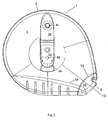
Fig. 1 is a plan view of a tape measure viewed from a first side, shown with the first winding handle retracted; -
Fig. 2 is a plan view of the tape measure viewed from the first side, shown with the first winding handle extended; -
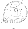
Fig. 3 is a plan view of the tape measure viewed from a second side, shown with the second winding handle retracted; -
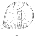
Fig. 4 is a plan view of the tape measure viewed from the second side, shown with the second winding handle extended; -
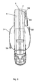
Fig. 5 is a plan view of an edge of the tape measure, shown with the first and second winding handles retracted; -
Fig. 6 is a plan view of an edge of the tape measure, shown with the first winding handle extended and the second winding handle retracted; -
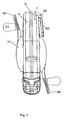
Fig. 7 is a plan view of an edge of the tape measure, shown with the first and second winding handles extended; and -
Fig. 8 is a cross-sectional view of a winding drum contained in the tape measure. - As shown in
Figs. 1 and2 , the tape measure comprises acasing 1 made from three injection moulded plastic parts. The two main parts are first andsecond casing halves shaped side wall - The casing has an edge wall formed from half walls (4, 7) which runs around the periphery of
respective side walls casing halves GB 2 369 103 - The tangential periphery of each
casing half point 9 of the teardrop. Instead, acurved edge casing half - A one-piece moulding 14 forms the tip of the teardrop shaped casing. As can be seen, the
moulding 14 is shaped to provide a smooth continuation of thecasing halves casing halves edges casing halves - The peripheral wall of the
moulding 14 includes aslot 19 through which the measuring tape can be drawn out, for use. - A
winding drum 22, shown in cross-section inFig. 8 , fits within thecasing 1. One end of the measuring tape (not shown) is attached to thisdrum 22, and the tape coils up around theouter surface 24 of this drum. This measuring tape may be made of material conventionally used for long tapes, such as steel or glass-reinforced fibre. - The
drum 22 comprises twoparts Annular surfaces drum 22 axially within the case. - One side of the
drum 22 has a slightlydomed surface 31. Achannel 32 bounded byparallel side walls 33 runs diametrically across thedomed surface 31. Alip 34 with a concave inner wall 35 closes one end of the channel.Pin 36 runs perpendicularly between the two channel side walls near, but spaced from, the opposite end of thechannel 32. One end of a first windinghandle 38 is hinged on thispin 36. - As shown in
Figs. 1 and5 when the first winding handle is not in use it lies within thechannel 32 and its upper surface is generally flush with the domes surface 31 of thedrum 22. When it is required to wind in the tape, thehandle 38 is turned outwards around thehinge pin 36 until its surface 40 abuts astop surface 39 on the floor of thechannel 32. This exposes a windingknob 41 rotatable on aspindle 42 projecting from the handle. When thehandle 38 is not in use thisspindle 42 and winding knob fit into arecess 46 in thedrum 22. - The second winding
handle 68 operates in exactly the same manner as the first windinghandle 38. - The casing halves 2, 5 include respective zones, opposite to each other, in which the two halves are specially shaped to assist the user in gripping the casing. These zones extend radially inwardly from the
edge walls faces - As seen in
Figs. 5 ,6 and7 , these shaped zones of the casing halves 2, 5 incorporate slight axially outward bulges 53 and 55. These meet the remainder of thefaces curved lines - As shown in the figures, a belt clip is provided by a
tongue 60 overlies a matching area cut out from theside wall 6. It is at an approximately uniform spacing from the level of the side wall, thus defining a slot between thetongue 60 and theside wall 6. Thetongue 60 is attached to the remainder of thecasing half 5 by anextension 62 from theedge wall 7. - To facilitate moulding the area of the
side wall 6 directly beneath thetongue 60 is cut out. The appearance is that this area of the side wall has been displaced outwards to form thetongue 60. - The tongue can be hooked over the belt of a user. The belt then fits in the slot between the
tongue 60 and theside wall 6.
Claims (3)
- A tape measure having a rotatably mounted winding drum or reel, and a measuring tape attached to the drum so as to be coilable thereon, characterised in that the tape measure has two winding handles (38, 68), one handle acting on each side of the drum.
- A tape measure according to claim 1, wherein at least one winding handle is retractable.
- A tape measure according to claim 2; wherein both winding handles are retractable.
Applications Claiming Priority (2)
| Application Number | Priority Date | Filing Date | Title |
|---|---|---|---|
| GBGB0427007.0A GB0427007D0 (en) | 2004-12-09 | 2004-12-09 | Tape measures |
| PCT/GB2005/004750 WO2006061641A1 (en) | 2004-12-09 | 2005-12-08 | Tape measure with two winding handles |
Publications (2)
| Publication Number | Publication Date |
|---|---|
| EP1831637A1 EP1831637A1 (en) | 2007-09-12 |
| EP1831637B1 true EP1831637B1 (en) | 2008-08-06 |
Family
ID=34073451
Family Applications (1)
| Application Number | Title | Priority Date | Filing Date |
|---|---|---|---|
| EP05818579A Expired - Lifetime EP1831637B1 (en) | 2004-12-09 | 2005-12-08 | Tape measure with two winding handles |
Country Status (7)
| Country | Link |
|---|---|
| US (1) | US20080010849A1 (en) |
| EP (1) | EP1831637B1 (en) |
| CN (1) | CN101087988A (en) |
| AT (1) | ATE403843T1 (en) |
| DE (1) | DE602005008772D1 (en) |
| GB (1) | GB0427007D0 (en) |
| WO (1) | WO2006061641A1 (en) |
Families Citing this family (3)
| Publication number | Priority date | Publication date | Assignee | Title |
|---|---|---|---|---|
| DE202006000836U1 (en) * | 2006-01-19 | 2007-05-24 | STABILA Messgeräte Gustav Ullrich GmbH | tape measure |
| US8356418B1 (en) * | 2011-07-16 | 2013-01-22 | Bruce Hall | Speed/agility/quickness (SAQ) skill measurement set-up assistant |
| WO2021178518A1 (en) * | 2020-03-04 | 2021-09-10 | Apex Brands, Inc. | Injection molded hinged knob |
Family Cites Families (10)
| Publication number | Priority date | Publication date | Assignee | Title |
|---|---|---|---|---|
| US308287A (en) * | 1884-11-18 | Tape-measure | ||
| US446487A (en) * | 1891-02-17 | Wire-reel | ||
| GB189401821A (en) * | 1894-01-27 | 1894-03-10 | Thomas Bedington | Improvements in Measuring Tapes. |
| GB191309015A (en) * | 1913-04-17 | 1914-03-26 | John Kenneth Rabone | Improvements in Tape Measures. |
| US3313498A (en) * | 1964-11-27 | 1967-04-11 | Lawrence W Wasson | Tie wire dispenser |
| US3347487A (en) * | 1965-10-22 | 1967-10-17 | Keuffel & Esser Co | Measuring tape device |
| US3630464A (en) * | 1968-10-30 | 1971-12-28 | William E Fagan | Reel device |
| US3844058A (en) * | 1973-06-08 | 1974-10-29 | J King | Down-rigger reel |
| US4251038A (en) * | 1978-04-03 | 1981-02-17 | Popeil Brothers, Inc. | Hose reel |
| GB9501562D0 (en) * | 1995-01-26 | 1995-03-15 | Fisco Products Ltd | Tape measure |
-
2004
- 2004-12-09 GB GBGB0427007.0A patent/GB0427007D0/en not_active Ceased
-
2005
- 2005-12-08 CN CNA2005800424385A patent/CN101087988A/en active Pending
- 2005-12-08 WO PCT/GB2005/004750 patent/WO2006061641A1/en not_active Ceased
- 2005-12-08 US US11/792,489 patent/US20080010849A1/en not_active Abandoned
- 2005-12-08 DE DE602005008772T patent/DE602005008772D1/en not_active Expired - Fee Related
- 2005-12-08 EP EP05818579A patent/EP1831637B1/en not_active Expired - Lifetime
- 2005-12-08 AT AT05818579T patent/ATE403843T1/en not_active IP Right Cessation
Also Published As
| Publication number | Publication date |
|---|---|
| EP1831637A1 (en) | 2007-09-12 |
| ATE403843T1 (en) | 2008-08-15 |
| CN101087988A (en) | 2007-12-12 |
| US20080010849A1 (en) | 2008-01-17 |
| WO2006061641A1 (en) | 2006-06-15 |
| DE602005008772D1 (en) | 2008-09-18 |
| GB0427007D0 (en) | 2005-01-12 |
Similar Documents
| Publication | Publication Date | Title |
|---|---|---|
| EP0724133B1 (en) | Tape measure | |
| US4527334A (en) | Power return tape | |
| US6249986B1 (en) | Rule assembly with protective film | |
| US4901938A (en) | Electrical cord retractor | |
| AU2018253626B2 (en) | Reel | |
| US5423516A (en) | Fish tape reel | |
| US6811109B1 (en) | Retainer for power-return tape measure spring | |
| JPS586881B2 (en) | Makishiyaku | |
| US6550155B1 (en) | Tape rule with automatic blade extension mechanism | |
| US4813625A (en) | Tape measure | |
| US3874608A (en) | Tape measure casing | |
| US11391555B2 (en) | Compact-sized tape measure | |
| US20060086863A1 (en) | Shipping spool | |
| US20080010849A1 (en) | Tape Measure With Two Winding Handles | |
| CA1045812A (en) | Tape reel with variable width hub | |
| EP1725828B1 (en) | Tape measure providing access to the spooled blade | |
| US6536698B2 (en) | Dual mode tape rule blade arrestor structure | |
| US7543772B2 (en) | Fishing line spool | |
| US4083508A (en) | Tape storage reel with insert for decreasing tape storage capacity | |
| US7036765B2 (en) | Polarized tape dispenser | |
| WO2005014451A3 (en) | Ergonomic center handle fish tape | |
| HK85893A (en) | Tape cassette | |
| GB2135969A (en) | A tape measure | |
| US2923490A (en) | Reel assembly for kite-lines and the like | |
| JPH10291579A (en) | Cassette storage case |
Legal Events
| Date | Code | Title | Description |
|---|---|---|---|
| PUAI | Public reference made under article 153(3) epc to a published international application that has entered the european phase |
Free format text: ORIGINAL CODE: 0009012 |
|
| 17P | Request for examination filed |
Effective date: 20070626 |
|
| AK | Designated contracting states |
Kind code of ref document: A1 Designated state(s): AT BE BG CH CY CZ DE DK EE ES FI FR GB GR HU IE IS IT LI LT LU LV MC NL PL PT RO SE SI SK TR |
|
| RIN1 | Information on inventor provided before grant (corrected) |
Inventor name: LEE, BARRY, HOWARD |
|
| GRAP | Despatch of communication of intention to grant a patent |
Free format text: ORIGINAL CODE: EPIDOSNIGR1 |
|
| DAX | Request for extension of the european patent (deleted) | ||
| GRAS | Grant fee paid |
Free format text: ORIGINAL CODE: EPIDOSNIGR3 |
|
| GRAA | (expected) grant |
Free format text: ORIGINAL CODE: 0009210 |
|
| AK | Designated contracting states |
Kind code of ref document: B1 Designated state(s): AT BE BG CH CY CZ DE DK EE ES FI FR GB GR HU IE IS IT LI LT LU LV MC NL PL PT RO SE SI SK TR |
|
| REG | Reference to a national code |
Ref country code: GB Ref legal event code: FG4D |
|
| REG | Reference to a national code |
Ref country code: CH Ref legal event code: EP |
|
| REG | Reference to a national code |
Ref country code: IE Ref legal event code: FG4D |
|
| REF | Corresponds to: |
Ref document number: 602005008772 Country of ref document: DE Date of ref document: 20080918 Kind code of ref document: P |
|
| PG25 | Lapsed in a contracting state [announced via postgrant information from national office to epo] |
Ref country code: LT Free format text: LAPSE BECAUSE OF FAILURE TO SUBMIT A TRANSLATION OF THE DESCRIPTION OR TO PAY THE FEE WITHIN THE PRESCRIBED TIME-LIMIT Effective date: 20080806 Ref country code: IS Free format text: LAPSE BECAUSE OF FAILURE TO SUBMIT A TRANSLATION OF THE DESCRIPTION OR TO PAY THE FEE WITHIN THE PRESCRIBED TIME-LIMIT Effective date: 20081206 Ref country code: NL Free format text: LAPSE BECAUSE OF FAILURE TO SUBMIT A TRANSLATION OF THE DESCRIPTION OR TO PAY THE FEE WITHIN THE PRESCRIBED TIME-LIMIT Effective date: 20080806 |
|
| PG25 | Lapsed in a contracting state [announced via postgrant information from national office to epo] |
Ref country code: SI Free format text: LAPSE BECAUSE OF FAILURE TO SUBMIT A TRANSLATION OF THE DESCRIPTION OR TO PAY THE FEE WITHIN THE PRESCRIBED TIME-LIMIT Effective date: 20080806 Ref country code: AT Free format text: LAPSE BECAUSE OF FAILURE TO SUBMIT A TRANSLATION OF THE DESCRIPTION OR TO PAY THE FEE WITHIN THE PRESCRIBED TIME-LIMIT Effective date: 20080806 Ref country code: ES Free format text: LAPSE BECAUSE OF FAILURE TO SUBMIT A TRANSLATION OF THE DESCRIPTION OR TO PAY THE FEE WITHIN THE PRESCRIBED TIME-LIMIT Effective date: 20081117 Ref country code: LV Free format text: LAPSE BECAUSE OF FAILURE TO SUBMIT A TRANSLATION OF THE DESCRIPTION OR TO PAY THE FEE WITHIN THE PRESCRIBED TIME-LIMIT Effective date: 20080806 Ref country code: FI Free format text: LAPSE BECAUSE OF FAILURE TO SUBMIT A TRANSLATION OF THE DESCRIPTION OR TO PAY THE FEE WITHIN THE PRESCRIBED TIME-LIMIT Effective date: 20080806 |
|
| PG25 | Lapsed in a contracting state [announced via postgrant information from national office to epo] |
Ref country code: BE Free format text: LAPSE BECAUSE OF FAILURE TO SUBMIT A TRANSLATION OF THE DESCRIPTION OR TO PAY THE FEE WITHIN THE PRESCRIBED TIME-LIMIT Effective date: 20080806 |
|
| PG25 | Lapsed in a contracting state [announced via postgrant information from national office to epo] |
Ref country code: BG Free format text: LAPSE BECAUSE OF FAILURE TO SUBMIT A TRANSLATION OF THE DESCRIPTION OR TO PAY THE FEE WITHIN THE PRESCRIBED TIME-LIMIT Effective date: 20081106 Ref country code: DK Free format text: LAPSE BECAUSE OF FAILURE TO SUBMIT A TRANSLATION OF THE DESCRIPTION OR TO PAY THE FEE WITHIN THE PRESCRIBED TIME-LIMIT Effective date: 20080806 |
|
| PGFP | Annual fee paid to national office [announced via postgrant information from national office to epo] |
Ref country code: FR Payment date: 20081222 Year of fee payment: 4 |
|
| PG25 | Lapsed in a contracting state [announced via postgrant information from national office to epo] |
Ref country code: PT Free format text: LAPSE BECAUSE OF FAILURE TO SUBMIT A TRANSLATION OF THE DESCRIPTION OR TO PAY THE FEE WITHIN THE PRESCRIBED TIME-LIMIT Effective date: 20090106 Ref country code: RO Free format text: LAPSE BECAUSE OF FAILURE TO SUBMIT A TRANSLATION OF THE DESCRIPTION OR TO PAY THE FEE WITHIN THE PRESCRIBED TIME-LIMIT Effective date: 20080806 Ref country code: SK Free format text: LAPSE BECAUSE OF FAILURE TO SUBMIT A TRANSLATION OF THE DESCRIPTION OR TO PAY THE FEE WITHIN THE PRESCRIBED TIME-LIMIT Effective date: 20080806 Ref country code: CZ Free format text: LAPSE BECAUSE OF FAILURE TO SUBMIT A TRANSLATION OF THE DESCRIPTION OR TO PAY THE FEE WITHIN THE PRESCRIBED TIME-LIMIT Effective date: 20080806 |
|
| PGFP | Annual fee paid to national office [announced via postgrant information from national office to epo] |
Ref country code: DE Payment date: 20081223 Year of fee payment: 4 |
|
| PLBE | No opposition filed within time limit |
Free format text: ORIGINAL CODE: 0009261 |
|
| STAA | Information on the status of an ep patent application or granted ep patent |
Free format text: STATUS: NO OPPOSITION FILED WITHIN TIME LIMIT |
|
| 26N | No opposition filed |
Effective date: 20090507 |
|
| PG25 | Lapsed in a contracting state [announced via postgrant information from national office to epo] |
Ref country code: MC Free format text: LAPSE BECAUSE OF NON-PAYMENT OF DUE FEES Effective date: 20081231 Ref country code: EE Free format text: LAPSE BECAUSE OF FAILURE TO SUBMIT A TRANSLATION OF THE DESCRIPTION OR TO PAY THE FEE WITHIN THE PRESCRIBED TIME-LIMIT Effective date: 20080806 |
|
| PG25 | Lapsed in a contracting state [announced via postgrant information from national office to epo] |
Ref country code: IT Free format text: LAPSE BECAUSE OF FAILURE TO SUBMIT A TRANSLATION OF THE DESCRIPTION OR TO PAY THE FEE WITHIN THE PRESCRIBED TIME-LIMIT Effective date: 20080806 |
|
| REG | Reference to a national code |
Ref country code: IE Ref legal event code: MM4A |
|
| PG25 | Lapsed in a contracting state [announced via postgrant information from national office to epo] |
Ref country code: IE Free format text: LAPSE BECAUSE OF NON-PAYMENT OF DUE FEES Effective date: 20081208 |
|
| PG25 | Lapsed in a contracting state [announced via postgrant information from national office to epo] |
Ref country code: SE Free format text: LAPSE BECAUSE OF FAILURE TO SUBMIT A TRANSLATION OF THE DESCRIPTION OR TO PAY THE FEE WITHIN THE PRESCRIBED TIME-LIMIT Effective date: 20081106 |
|
| PG25 | Lapsed in a contracting state [announced via postgrant information from national office to epo] |
Ref country code: PL Free format text: LAPSE BECAUSE OF FAILURE TO SUBMIT A TRANSLATION OF THE DESCRIPTION OR TO PAY THE FEE WITHIN THE PRESCRIBED TIME-LIMIT Effective date: 20080806 |
|
| PG25 | Lapsed in a contracting state [announced via postgrant information from national office to epo] |
Ref country code: HU Free format text: LAPSE BECAUSE OF FAILURE TO SUBMIT A TRANSLATION OF THE DESCRIPTION OR TO PAY THE FEE WITHIN THE PRESCRIBED TIME-LIMIT Effective date: 20090207 Ref country code: LU Free format text: LAPSE BECAUSE OF NON-PAYMENT OF DUE FEES Effective date: 20081208 Ref country code: CY Free format text: LAPSE BECAUSE OF FAILURE TO SUBMIT A TRANSLATION OF THE DESCRIPTION OR TO PAY THE FEE WITHIN THE PRESCRIBED TIME-LIMIT Effective date: 20080806 |
|
| REG | Reference to a national code |
Ref country code: CH Ref legal event code: PL |
|
| GBPC | Gb: european patent ceased through non-payment of renewal fee |
Effective date: 20091208 |
|
| PG25 | Lapsed in a contracting state [announced via postgrant information from national office to epo] |
Ref country code: TR Free format text: LAPSE BECAUSE OF FAILURE TO SUBMIT A TRANSLATION OF THE DESCRIPTION OR TO PAY THE FEE WITHIN THE PRESCRIBED TIME-LIMIT Effective date: 20080806 |
|
| REG | Reference to a national code |
Ref country code: FR Ref legal event code: ST Effective date: 20100831 |
|
| PG25 | Lapsed in a contracting state [announced via postgrant information from national office to epo] |
Ref country code: FR Free format text: LAPSE BECAUSE OF NON-PAYMENT OF DUE FEES Effective date: 20091231 Ref country code: CH Free format text: LAPSE BECAUSE OF NON-PAYMENT OF DUE FEES Effective date: 20091231 Ref country code: LI Free format text: LAPSE BECAUSE OF NON-PAYMENT OF DUE FEES Effective date: 20091231 Ref country code: GR Free format text: LAPSE BECAUSE OF FAILURE TO SUBMIT A TRANSLATION OF THE DESCRIPTION OR TO PAY THE FEE WITHIN THE PRESCRIBED TIME-LIMIT Effective date: 20081107 |
|
| PG25 | Lapsed in a contracting state [announced via postgrant information from national office to epo] |
Ref country code: DE Free format text: LAPSE BECAUSE OF NON-PAYMENT OF DUE FEES Effective date: 20100701 |
|
| PG25 | Lapsed in a contracting state [announced via postgrant information from national office to epo] |
Ref country code: GB Free format text: LAPSE BECAUSE OF NON-PAYMENT OF DUE FEES Effective date: 20091208 |