EP1831502B1 - Centralizer-based survey and navigation device and method - Google Patents
Centralizer-based survey and navigation device and method Download PDFInfo
- Publication number
- EP1831502B1 EP1831502B1 EP05854063.4A EP05854063A EP1831502B1 EP 1831502 B1 EP1831502 B1 EP 1831502B1 EP 05854063 A EP05854063 A EP 05854063A EP 1831502 B1 EP1831502 B1 EP 1831502B1
- Authority
- EP
- European Patent Office
- Prior art keywords
- metrology
- centralizer
- sensor
- navigation
- centralizers
- Prior art date
- Legal status (The legal status is an assumption and is not a legal conclusion. Google has not performed a legal analysis and makes no representation as to the accuracy of the status listed.)
- Not-in-force
Links
Images


Classifications
-
- E—FIXED CONSTRUCTIONS
- E21—EARTH DRILLING; MINING
- E21B—EARTH DRILLING, e.g. DEEP DRILLING; OBTAINING OIL, GAS, WATER, SOLUBLE OR MELTABLE MATERIALS OR A SLURRY OF MINERALS FROM WELLS
- E21B47/00—Survey of boreholes or wells
- E21B47/02—Determining slope or direction
- E21B47/022—Determining slope or direction of the borehole, e.g. using geomagnetism
-
- E—FIXED CONSTRUCTIONS
- E21—EARTH DRILLING; MINING
- E21B—EARTH DRILLING, e.g. DEEP DRILLING; OBTAINING OIL, GAS, WATER, SOLUBLE OR MELTABLE MATERIALS OR A SLURRY OF MINERALS FROM WELLS
- E21B17/00—Drilling rods or pipes; Flexible drill strings; Kellies; Drill collars; Sucker rods; Cables; Casings; Tubings
- E21B17/10—Wear protectors; Centralising devices, e.g. stabilisers
- E21B17/1057—Centralising devices with rollers or with a relatively rotating sleeve
Definitions
- the present invention relates to an apparatus for accurately determining in three dimensions information on the location of an object in a passageway and/or the path taken by a passageway, e.g., a borehole or tube.
- the drilling industry has recognized the desirability of having a position determining system that can be used to guide a drilling head to a predestined target location.
- a position determining system that can provide accurate position information on the path of a borehole and/or the location of a drilling head at any given time as the drill pipe advances.
- the position determining system would be small enough to fit into a drill pipe so as to present minimal restriction to the flow of drilling or returning fluids and accuracy should be as high as possible.
- Some shallow depth position location systems are based on tracking sounds or electromagnetic radiation emitted by a sonde near the drilling head. In addition to being depth limited, such systems are also deficient in that they require a worker to carry a receiver and walk the surface over the drilling head to detect the emissions and track the drilling head location. Such systems cannot be used where there is no worker access to the surface over the drilling head or the ground is not sufficiently transparent to the emissions.
- the '628 patent system constructs on a segment-by-segment basis, circular arc data representing the path of the borehole and which also represents, at each measurement point, the location of the measuring strain gauge sensors. If the sensors are positioned near the drilling head, the location of the drilling head can be obtained.
- the '628 patent system and method has application for directional drilling and can be used with various types of drilling apparatus, for example, rotary drilling, water jet drilling, down hole motor drilling, and pneumatic drilling.
- the system is useful in directional drilling such as well drilling, reservoir stimulation, gas or fluid storage, routing of original piping and wiring, infrastructure renewal, replacement of existing pipe and wiring, instrumentation placement, core drilling, cone penetrometer insertion, storage tank monitoring, pipe jacking, tunnel boring and in other related fields.
- the '628 patent also provides a method for compensating for rotation of the measuring tube during a drilling operation by determining, at each measurement position, information concerning the net amount of rotation relative to a global reference, if any, of the measuring tube as it passes through the passageway and using the rotation information with the strain measurement to determine the azimuth associated with a measured local radius of curvature relative to the global reference.
- US patent number 4 399 692 describes a downhole probe provided with two or more sections connected by torsionally rigid, flexible joint assemblies with provisions for generating signals that represent the relative inclination and azimuth of one probe section from another. These signals are combined with inclination signals obtained from a set of accelerometers in one of the probe sections in a signal processing unit to generate signals that represent the direction and depth of the borehole.
- US patent number 5 947 213 describes a system for performing a desired operation in a wellbore.
- the system contains a downhole tool which includes a mobility platform that is electrically operated to move the downhole tool in the wellbore and an end work device to perform the desired work.
- the downhole tool also includes an imaging device to provide pictures of the downhole environment.
- the data from the downhole tool is communicated to a surface computer, which controls the operation of the tool and displays pictures of the tool environment. Tactile sensors for use as imaging devices are also provided.
- the downhole tool is composed of a base unit and a detachable work unit.
- the work unit includes the mobility platform, imaging device and the end work device.
- the tool is conveyed into the wellbore by a conveying member.
- the work unit detaches itself from the base unit, travels to the desired location in the wellbore and performs a predefined operation according to programmed instruction stored in the work unit.
- the work unit returns to the base unit, where it transfers data relating to the operation and can be recharged for further operation.
- US patent number 5 603 386 discloses a downhole tool connectable to a drill string by a connection atop the tool.
- the downhole tool includes a mandrel for connection with the drill string, the mandrel being rotatable within a body.
- a plurality of blades are individually extendible radially from the body to engage the wall of a well bore, the radial position of the blades being adjustable between a first retracted position and a second extended position to position the centre line of the mandrel at a desired position relative to the longitudinal axis of the well bore.
- a positioning system is provided to hold each of the blades at the retracted position, the extended position or at any intermediate position therebetween.
- a survey and navigation metrology device comprising:
- the Centralizer-based Survey and Navigation (CSN) device is designed to provide borehole or passageway position information.
- the device is suitable for both closed traverse surveying (referred to as survey) and open traverse surveying or navigation while drilling (referred to as navigation).
- the CSN device can consist of a sensor string comprised of one or more segments having centralizers, which position the segment(s) within the passageway, and at least one metrology sensor, which measures the relative positions and orientation of the centralizers, even with respect to gravity.
- the CSN device can also have at least one odometry sensor, an initialization system, and a navigation algorithm implementing processor(s).
- the number of centralizers in the sensor string should be at least three. Additional sensors, such as inclinometers, accelerometers, and others can be included in the CSN device and system.
- each segment can have its own detector to measure relative positions of centralizers, its own detector that measures relative orientation of the sensor string with respect to gravity, and/or where the partial data reduction is performed by a processor placed inside the segment and high value data is communicated to the navigation algorithm processor through a bus.
- Another exemplary embodiment relates to a CSN device utilizing a sensor string segment which can utilize capacitance proximity detectors and/or fiber optic proximity detectors and/or strain gauges based proximity detectors that measure relative positions of centralizers with respect to a reference straight metrology body or beam.
- Another exemplary embodiment relates to a CSN device utilizing an angular metrology sensor, which has rigid beams as sensor string segments that are attached to one or more centralizers. These beams are connected to each other using a flexure-based joint with strain gauge instrumented flexures and/or a universal joint with an angle detector such as angular encoder. The relative positions of the centralizers are determined based on the readings of the said encoders and/or strain gauges.
- Another exemplary embodiment relates to a CSN device utilizing a strain gauge instrumented bending beam as a sensor string segment, which can use the readings of these strain gauges to measure relative positions of the centralizers.
- Another exemplary embodiment relates to a CSN device utilizing a bending beam sensor, which can utilize multiple sets of strain gauges to compensate for possible shear forces induced in the said bending beam.
- Another exemplary embodiment relates to a compensator for zero drift of detectors measuring orientation of the sensor string and detectors measuring relative displacement of the centralizers by inducing rotation in the sensor string or taking advantage of rotation of a drill string.
- the detector measuring orientation of the sensor string is an accelerometer
- such a device can calculate the zero drift of the accelerometer detector by enforcing that the average of the detector-measured value of local Earth's gravity to be equal to the known value of g at a given time, and/or where the zero drift of detectors measuring relative displacement of the centralizers is compensated for by enforcing that the readings of the strain gauges follow the same angular dependence on the rotation of the string as the angular dependence measured by inclinometers, accelerometers, and or gyroscopes placed on the drill string or sensor string that measure orientation of the sensor string with respect to the Earth's gravity.
- Another exemplary embodiment relates to a device using buoyancy to compensate for the gravity induced sag of the metrology beam of the proximity-detector-based or angular-metrology-based displacement sensor string.
- Another exemplary embodiment relates to centralizers that maintain constant separation between their points of contact with the borehole.
- the invention relates to a Centralizer-based Survey and Navigation (hereinafter "CSN") metrology device, designed to provide passageway and down-hole position information.
- CSN Centralizer-based Survey and Navigation
- the CSN device can be scaled for use in passageways and holes of almost any size and is suitable for survey of or navigation in drilled holes, piping, plumbing, municipal systems, and virtually any other hole environment.
- passageway and borehole are used interchangeably.
- FIG. 1 shows the basic elements of a directional drilling system incorporating a CSN device 10, a sensor string 12 including segments 13 and centralizers 14 (14a, 14b, and 14c), a drill string 18, an initializer 20, an odometer 22, a computer 24, and a drill head 26.
- a metrology sensor 28 is included and can be associated with the middle centralizer 14b, or located on the drill string 18.
- the odometer 22 and computer 24 hosting a navigation algorithm are, typically, installed on a drill rig 30 and in communication with the CSN device 10.
- a CSN device 10 may be pre-assembled before insertion into the borehole 16 or may be assembled as the CSN device 10 advances into the borehole 16.
- the CSN device 10 can be placed onto a drill string 18 and advanced into the borehole 16.
- the centralizers 14 of the CSN device 10 which are shown and discussed in greater detail below in relation to FIGs. 19-20b , are mechanical or electromechanical devices that position themselves in a repeatable fashion in the center of the borehole 16 cross-section, regardless of hole wall irregularities.
- a CSN device 10, as shown in FIG. 1 uses at least three centralizers 14: a trailing centralizer 14a, a middle centralizer 14b, and a leading centralizer 14c, so named based on direction of travel within the borehole 16.
- the centralizers 14 are connected along a sensor string 12 in one or more segments 13, which connect any two centralizers 14, to maintain a known, constant spacing in the borehole 16 and between the connected centralizers 14.
- Direction changes of the CSN device 10 evidenced by changes in orientation of the centralizers 14 with respect to each other or with respect to the sensor string 12 segments 13 can be used to determine the geometry of borehole 16.
- the initializer 20, shown in FIG. 1 provides information on the borehole 16 and CSN device 10 insertion orientation with respect to the borehole 16 so that future calculations on location can be based on the initial insertion location.
- the initializer 20 has a length that is longer than the distance between a pair of adjacent centralizers 14 on the sensor string segment 13, providing a known path of travel into the borehole 16 for the CSN device 10 so that it may be initially oriented. Under some circumstances, information about location of as few as two points along the borehole 16 entranceway may be used in lieu of the initializer 20.
- Navigation in accordance with an exemplary embodiment of the invention provides the position location of the CSN device 10 with respect to its starting position and orientation based on data obtained by using the initializer 20.
- FIG. 2a there are various types of centralizer-based metrologies compatible with the CSN device 10;
- Figures 2a and 2d show CSN devices not forming part of the invention. All these devices can determine the position of the CSN device 10 based on readings at the CSN device 10.
- the types of CSN device 10 metrologies include, but are not limited to: (1) straight beam/angle metrology, shown in FIG. 2a ; (2) straight beam/displacement metrology, shown in FIG. 2b ; (3) bending beam metrology, shown in FIG. 2c ; (4) optical beam displacement metrology, shown in FIG. 2d ; and ( 5 ) combination systems of (1)-(4), shown in FIG. 2e .
- the CSN device 10 uses this borehole 16 curvature information along with distance traveled along the borehole 16 to determine its location in three dimensions. Distance traveled within the borehole 16 from the entry point to a current CSN device 10 location can be measured with an odometer 22 connected either to the drill string 18 used to advance the CSN device 10 or connected with the CSN device 10 itself.
- the CSN device 10 can be in communication with a computer 24, which can be used to calculate location based on the CSN device 10 measurements and the odometer 22.
- the CSN device 10 itself can include all instrumentation and processing capability to determine its location and the connected computer 24 can be used to display this information.
- a navigation algorithm such as that shown in FIG. 6 , can combine the readings of the sensor string segment(s) 12, the odometry sensor(s) 22, and the initializer 20 to calculate the borehole 16 position of the CSN device 10.
- a CSN device 10 provides the relative positions of the centralizers 14. More precisely, an ideal three-centralizer CSN device 10 provides vector coordinates of the leading centralizer 14c in a local coordinate system, as shown by FIG. 5b , where the "x" axis is defined by the line connecting the centralizers 14a and 14c and the "z" axis lies in a plane defined by the "x" axis and the global vertical “Z.” Alternately, the position of the middle centralizer would be provided in a coordinate system where the "x" axis is defined by the line connecting the centralizers 14a and 14b and the "y" axis and "z” axis are defined same as above. Coordinate systems where the x axis connects either leading and trailing centralizers, or leading and middle centralizer, or middle and trailing centralizers, while different in minor details, all lead to mathematically equivalent navigation algorithms and will be used interchangeably.
- FIG. 3 illustrates a CSN device 10 in accordance with the metrology technique shown in FIG. 2a , where angle of direction change between the leading centralizer 14c and trailing centralizer 14a is measured at the middle centralizer 14b.
- the CSN device 10 follows the drill head 26 through the borehole 16 as it changes direction.
- the magnitude of displacement of the centralizers 14 with respect to each other is reflected by an angle ⁇ between the beam forming segment 13 connecting the centralizers 14c and 14b and the beam forming segment 13 connecting the centralizers 14b and 14a, which is measured by angle-sensing detector(s) 29 (a metrology sensor 28) at or near the middle centralizer 14b.
- Rotation ⁇ of the sensor string 12 can also be measured.
- FIG. 4 shows a CSN device 10 configured for an alternative navigation/survey technique reflecting the metrology techniques shown in FIGs. 2b, 2c , and 2e , i.e., both displacement and bending/strain metrology.
- Displacement metrology measures relative positions of the centralizers 14 using a straight displacement metrology beam 31 (as a sensor string 12 segment 13) that is mounted on the leading and trailing centralizers, 14c and 14a.
- Proximity detectors 38 (a metrology sensor 28) measure the position of the middle centralizer 14b with respect to the straight metrology beam 31.
- strain detector metrology can also be used in the CSN device 10, which is configured to measure the strain induced in a solid metrology beam 32 (another form of sensor string segment 12) that connects between each of the centralizers 14. Any deviation of the centralizer 14 positions from a straight line will introduce strains in the beam 32.
- the strain detectors or gauges 40 (a type of metrology sensor 28) measure these strains (the terms strain detectors and strain gauges are used interchangeably herein).
- the strain gages 40 are designed to convert mechanical motion into an electronic signal.
- the CSN device 10 can have as few as two strain gauge instrumented intervals in the beam 32. Rotation ⁇ of the sensor string 12 can also be measured.
- both strain detectors 40 and proximity detectors 38 may be used simultaneously to improve navigation accuracy.
- the displacement metrology is based on a deviation of the beam of light such as a laser beam.
- a coherent, linear light source e.g., laser
- a reflecting surface mounted on trailing centralizer 14a reflects the coherent light back to a position sensitive optical detector (PSD, a metrology sensor 28) mounted on middle centralizer 14b, which converts the reflected location of the coherent light into an electronic signal.
- PSD position sensitive optical detector
- the point at which the beam intersects the PSD metrology sensor 28 is related to the relative displacement of the three centralizers 14.
- a two centralizer 14 optical metrology sensor arrangement In a two centralizer 14 optical metrology sensor arrangement, light from a laser mounted on a middle centralizer 14b is reflected from a mirror mounted on an adjacent centralizer 14 and redirected back to a PSD metrology sensor 28 mounted on the middle centralizer 14b.
- the point at which the beam intersects the PSD metrology sensor 28 is related to the relative angle of the orientation of the centralizers 14.
- a CSN navigation algorithm uses a local coordinate system (x, y, z) to determine the location of a CSN device 10 in three dimensions relative to a Global coordinate system (X, Y, Z).
- FIG. 5a indicates the general relationship between the two coordinate systems where the local coordinates are based at a location of CSN device 10 along borehole 16 beneath the ground surface.
- a CSN navigation algorithm can be based on the following operation of the CSN device 10: (1) the CSN device 10 is positioned in such a way that the trailing centralizer 14a and the middle centralizer 14b are located in a surveyed portion (the known part) of the borehole 16 and the leading centralizer 14c is within an unknown part of the borehole 16; (2) using displacement metrology, a CSN device 10 comprises a set of detectors, e.g., metrology sensor 28, that calculates the relative displacement of the centralizers 14 with respect to each other in the local coordinate system; (3) a local coordinate system is defined based on the vector connecting centralizers 14 a and 14c (axis "x" in FIG. 5b ) and the direction of the force of gravity (vertical or "Z" in FIG.
- the position of the leading centralizer 14c can be determined.
- An algorithm as shown in FIG. 6 applied by, e.g., a processor, and functioning in accordance with the geometry of FIG. 5c can perform as follows: (1) the CSN device 10 is positioned as indicated in the preceding paragraph; (2) the relative angular orientations ⁇ y , ⁇ z and positions ( y , z ) of any two adjacent sensor string segments 13 of a CSN device 10 in the local coordinate system are determined using internal CSN device 10 segment 13 detectors; (3) three centralizers 14 are designated to be the leading 14c, trailing 14a, and middle 14b centralizers of the equivalent or ideal three-centralizer CSN device 10; (4) relative positions of the leading, middle, and trailing centralizers 14 forming an ideal CSN device 10 are determined in the local coordinate system of the sensor string 12.
- FIG. 7a shows a CSN device 10 according to an alternative exemplary embodiment of the invention that utilizes straight beam displacement (such as shown in FIGs. 2b and 4 ) and capacitance measurements as metrology sensors 28 to calculate the respective locations of the centralizers 14a, 14b, and 14c.
- a stiff straight beam 31 is attached to the leading and trailing centralizers 14c and 14a by means of flexures 33 that are stiff in radial direction and flexible about the axial direction ( ⁇ ).
- a set of proximity detectors, 38 can be associated with the middle centralizer 14b. The proximity detectors 38 measure the displacement of the middle centralizer 14b with respect to the straight beam 31.
- An accelerometer 36 can be used to measure the orientation of the middle centralizer 14b with respect to the vertical.
- Examples of proximity detectors include, capacitance, eddy current, magnetic, strain gauge, and optical proximity detectors.
- the Global and Local coordinate systems ( FIGs. 5a-5d ) associated with the CSN device 10 of this embodiment are shown in FIG. 7a .
- FIG. 7b The relationship between these proximity detectors 38 and the straight beam 31 is shown in FIG. 7b as a cross-sectional view of the CSN device 10 of FIG. 7a taken through the center of middle centralizer 14b.
- the proximity detectors 38 measure position of the middle centralizer 14b in the local coordinate system as defined by the vectors connecting leading and trailing centralizers 14a and 14c and the vertical.
- the CSN device 10 as shown in FIGs. 7a and 7b can have an electronics package, which can include data acquisition circuitry supporting all detectors, including proximity detectors 38, strain gauges 40 ( FIG 8 ), inclinometers (e.g., the accelerometer 36), etc., and power and communication elements (not shown).
- d horizontal and d vertical are displacements in the vertical and orthogonal planes defined earlier
- d z and d y are the displacements measured by the capacitance detectors 38
- ⁇ is the angle of rotation of the capacitance detectors 38 with respect to the vertical as determined by the accelerometer(s) 36.
- z ⁇ g ⁇ ⁇ g ⁇ ⁇ x ⁇
- y ⁇ z ⁇ ⁇ x ⁇
- g ⁇ 0 0 1
- FIG. 8 shows a CSN device 10 with strain gauge detectors 40 attached to a bending beam 32.
- the circuit design associated with the resistance strain gauges 40 and accelerometer(s) 36 is shown below the CSN device 10. Any type of strain detector 40 and orientation detector, e.g., accelerometer 36, may be used.
- Each instrumented sensor string 12 segment 13, here the bending beam 32 (between centralizers 14) of the CSN device 10 can carry up to four, or more, sets of paired strain gauge detectors 40 (on opposite sides of the bending beam 32), each opposing pair forming a half-bridge.
- segments 13 may or may not be the same segments 13 that accommodate the capacitance detector 38 if the CSN device 10 utilizes such.
- strain gauge detector 40 and accelerometer 36 readings can be recorded simultaneously.
- a displacement detector supporting odometry correction ( ⁇ l ) can also be placed on at least one segment 13 (not shown).
- Several temperature detectors can also be place on each segment 13 to permit compensation for thermal effects.
- strain detector 40 pairs be mounted onto each sensor string segment 13 (between centralizers 14) as the minimum number of strain detectors 40.
- the circuit diagrams shown below the CSN device 10, with voltage outputs V z 1 , V y 1 , V z 2 , and V y 2 represent an exemplary wiring of these half-bridges.
- These detectors 40 can provide the relative orientation and relative position of the leading centralizer 14c with respect to the trailing centralizer 14a, or a total of four variables.
- At least one of the adjacent sensor string segments 13 between centralizers 14 should contain a detector (not shown) that can detect relative motion of the CSN device 10 with respect to the borehole 16 to determine the actual borehole 16 length when the CSN device 10 and drill string 18 are advanced therein.
- the variation of curvatures of the beam 32 likely cannot be achieved without some shear forces applied to centralizers 14.
- the preferred strain gauge detector 40 scheme of the CSN device 10 shown in FIG. 8 accounts for these shear forces.
- the exemplary circuit layout shown below the CSN device 10 and corresponding chart shows how the sensors 40 can be connected.
- FIG. 9 illustrates two dimensional resultant shear forces acting on centralizers 14 of a single sensor string segment 13 comprised of a bending bean 32 as shown in FIG. 8 .
- Four unknown variables, namely, two forces and two bending moments, should satisfy two equations of equilibrium: the total force and the total moment acting on the bending beam 32 are equal to zero.
- FIG. 9 shows the distribution of shear force T ⁇ and moments M ⁇ along the length of bending beam 32.
- ⁇ is the angle between the orientation of the beam 32 and the horizontal
- E is the Young Modulus of the beam 32 material
- I is the moment of inertia
- L is the length of the segment 12 as determined by the locations of centralizers 14.
- the values of the integrals are independent of the values of the applied moments and both integrals are positive numbers.
- FIG. 10 shows a block diagram for data reduction in a strain gauge CSN device 10, such as that shown in FIG. 9 .
- ⁇ is the torsion applied to a CSN device 10 segment 13 as measured by a torsion detector and p ⁇ is a calibration constant.
- the factors in Eq. 19 are the 2x2 rotation matrix in FIG. 10 .
- the thermal loads change the values of factors p i ⁇ . .
- the CTE's are calibration parameters. They include both material and material stiffness thermal dependences.
- strain gauge detectors 40 can be placed on an axially rotating beam 32 constrained at the centralizers 14 by fixed immovable borehole 16 walls forming a sensor string segment 12.
- Advantages in greater overall measurement accuracy from CSN device 10 that may be gained by rotating the beam 32 to create a time varying signal related to the amount of bending to which it is subjected may result from, but are not limited to, signal averaging over time to reduce the effects of noise in the signal and improved discrimination bending direction.
- the values of the ⁇ z and ⁇ y may be recovered by first performing a least square fit of ⁇ ( ⁇ ) into sine and cosine.
- FIG. 13 which relates to the accelerometer 36 described above as incorporated into the CSN device 10 electronics package as discussed in relation to FIGs. 7a and 8 .
- a tri-axial accelerometer 36 can be fully described by the following data where, relative to the Global vertical direction "Z," each component of the accelerometer has a calibrated electrical output (Gauge factor), a known, fixed spatial direction relative to the other accelerometer 36 components (Orientation), and a measured angle of rotation about its preferred axis of measurement (Angular Location): Gauge factor Angular Location Orientation Accelerometer X mV/g ⁇ yz N X , N Y , N Z Accelerometer Y mV/g ⁇ y z N X , N Y , N Z Accelerometer Z mV/g ⁇ yz N X , N Y , N Z
- a
- ⁇ g a c o ⁇ g ⁇ sin ⁇ + g ⁇ cos ⁇ ⁇ c 1 ⁇ sin ⁇ + c 2 ⁇ cos ⁇ where fit parameters c 0 , c 1 , and c 2 are determined during initial calibration of the tri-axial accelerometer 36 and g is the Earth's gravitational constant.
- a data reduction algorithm corrects accelerometer 36 readings for zero offset drift and angular velocity.
- Such an algorithm can be used by a zero drift compensator, including a processor, with a CSN device 10 as shown in FIG. 11 , for example.
- the zero drift compensator works by rotating the CSN device 10.
- a zero drift compensator can operate by enforcing a rule that the average of the measured value of g be equal to the know value of g at a given time.
- a zero drift compensator can operate by enforcing a rule that the strain readings of the strain gauges 40 follow the same angular dependence on the rotation of the string 12 as the angular dependence recorded by the accelerometers 36.
- a zero drift compensator can operate by enforcing a rule that the strain readings of the strain gauges 40 follow a same angular dependence as that measured by angular encoders placed on the drill string 18 ( FIG. 1 ) or sensor string 12.
- a ⁇ c 0 ⁇ ⁇ g ⁇ sin ⁇ + g ⁇ cos ⁇ ⁇ c 1 ⁇ ⁇ sin ⁇ + c 2 ⁇ ⁇ cos ⁇ + of f ⁇ + c 3 ⁇ ⁇ ⁇ 2
- off is the zero offset of the accelerometer
- ⁇ is the angular velocity of rotation
- index ⁇ refers to the local x, y, and z coordinate system. Equation 35 can be solved for the angles.
- the values of the twelve constants d j ⁇ are determined during calibration.
- V i 2 d 2 X ⁇ a i X + d 2 Y ⁇ a i Y + d 2 Z ⁇ a i Z
- V i 3 d 3 X ⁇ a i X + d 3 Y ⁇ a i Y + d 3 Z ⁇ a Z ⁇ O
- F 1 d 1 X ⁇ of f X + d 1 Y ⁇ of f Y + d 1 Z ⁇ of f Z
- F 2 d 2 X ⁇ of f X +
- ⁇ 2 ⁇ V i 1 ⁇ t 2 + ⁇ V i 2 ⁇ t 2 cos 2 ⁇ i ⁇ ⁇ V i 1 ⁇ t 2 + ⁇ V i 2 ⁇ t 2 1 ⁇ V i 3 2 ⁇ ⁇ V i 1 ⁇ t 2 + ⁇ V i 2 ⁇ t 2
- offsets OF 1 , OF 2 , OF 3 are determined by the least square fit, i.e., by minimizing, as follows: min ⁇ i V i 1 ⁇ O F 1 ⁇ d 1 ⁇ ⁇ ⁇ 2 2 + V i 2 ⁇ O F 2 ⁇ d 2 ⁇ ⁇ ⁇ 2 2 + V i 3 ⁇ O F 3 ⁇ d 3 ⁇ ⁇ ⁇ 2 2 ⁇ 1 2
- FIGs. 15-17 each of which shows a universal joint angle measurement sensor 50, which is an alternative embodiment to the strain gauge displacement CSN device 10 embodiments discussed above in relation to, e.g., FIGs. 2c and 8 .
- the universal joint 50 can be cylindrical in shape to fit in a borehole 16 or tube and is comprised of two members 56 joined at two sets of opposing bendable flexures 54 such that the joint 50 may bend in all directions in any plane orthogonal to its length.
- the bendable flexures 54 are radially positioned with respect to an imaginary center axis of the universal joint 50.
- Each one of the two sets of bendable flexures 54 allows for flex in the joint 50 along one plane along the imaginary center axis.
- Each plane of flex is orthogonal to the other, thus allowing for flex in all directions around the imaginary center axis.
- the strain forces at the bendable flexures 54 are measured in much the same way as those on the strain gauge detectors 40 of the CSN device 10 of FIG. 8 using detectors 52.
- Spatial orientation of universal joint 50 relative to the vertical may be measured by a tri-axial accelerometer 57 attached to the interior of universal joint 50.
- the universal joint 50 may be connected to a middle centralizer 14b of a CSN device 10 as shown in FIG. 16 .
- a spring 58 can be used to activate the centralizer 14b (this will be explained in further detail below with reference to FIGs. 19-20b ).
- the universal joint 50 and middle centralizer 14b are rigidly attached to each other and connected with arms 44 to leading and trailing centralizers 14a and 14c.
- the universal joint 50 when located on a CSN device 10 for use as a downhole tool for survey and/or navigation, is positioned at or near a middle centralizer 14b of three centralizers 14.
- the two outer centralizers 14a and 14c are connected to the universal joint 50 by arms 44, as shown in FIG. 17 , which may house electronics packages if desired.
- the universal joint 50 includes strain gauges 52 ( FIG. 15 ) to measure the movement of the joint members 56 and arms 44.
- the CSN device 10 of the various embodiments is used for the survey of boreholes 16 or passageways and navigation of downhole devices; the goal of the navigation algorithm ( FIG. 6 ) is to determine relative positions of the centralizers 14 of the CSN device 10 and to determine the borehole 16 location of the CSN device 10 based on that data. Now referring to FIG. 6 , the navigation algorithm ( FIG. 6 ) is to determine relative positions of the centralizers 14 of the CSN device 10 and to determine the borehole 16 location of the CSN device 10 based on that data.
- the reading of strain gauges, e.g., 52 as shown in FIG. 15 provide the angles ⁇ y , ⁇ z of the CSN device 10 segment leading centralizer 14c position in the local coordinate system.
- Eq. 45 and 46 one can define the origin and the orientation of the CSN device 10 portion in the unknown region of a borehole 16 in the first local coordinate system. After applying equations 45 and 46 to all CSN device 10 segments 13, the location of the CSN device 10 portion in the unknown region of a borehole 16 is determined.
- the shape of the CSN device 10 is defined up to the accuracy of the strain gauges 40 or 52.
- the inclination of the CSN device 10 with respect to the vertical is defined within the accuracy of the accelerometers 36 or 57.
- the azimuth orientation of the CSN device 10 is not known.
- centralizers 14 are used to accurately and repeatably position the metrology sensors 28 ( FIG. 1 ) discussed above within a borehole 16. Additionally, the centralizer 14 has a known pivot point 60 that will not move axially relative to the metrology article to which it is attached.
- the centralizer 14 is configured to adapt straight line mechanisms to constrain the centralizer 14 pivot point 60 to axially remain in the same lateral plane. This mechanism, sometimes referred to as a "Scott Russell” or "Evan's" linkage, is composed of two links, 64 as shown in FIG. 19 , and 64a and 64b as shown in FIGs.
- the shorter link 64b of FIGs. 20a and 20b has a fixed pivot point 60b, while the longer link 64a has a pivot point 60a free to move axially along the tube housing 34.
- the links 64a and 64b are joined at a pivot point 66, located half-way along the length of the long link 64a, while the short link 64b is sized so that the distance from the fixed point 60b to the linked pivot 66 is one half the length of the long link 64a.
- This centralizer 14 mechanism is formed by placing a spring 68 behind the sliding pivot point 60a, which provides an outward forcing load on the free end of the long link 64a.
- This design can use roller bearings at pivot points, but alternatively they could be made by other means, such as with a flexure for tighter tolerances, or with pins in holes if looser tolerances are allowed.
- a roller 62 is positioned at the end of the long link 64a to contact the borehole 16 wall.
- FIG. 19 shows a centralizer 14 embodiment with a double roller, fixed pivot point 60.
- This embodiment has two spring-loaded 68 rollers 62 centered around a fixed pivot point 60.
- FIGs. 20a and 20b have a single roller structure, also with a single fixed pivot point 60, but with one spring-loaded 68 roller 62.
- a device is utilized for canceling the effects of gravity on a mechanical beam to mitigate sag.
- a device is utilized for canceling the effects of gravity on a mechanical beam to mitigate sag.
- FIGs. 21a and 21b using buoyancy to compensate for gravity-induced sag of a metrology beam of a CSN device 10 having a proximity-detector-based or angular-metrology-based displacement sensor string, accuracy of the survey or navigation can be improved.
- an angle measuring metrology sensor CSN device 10 can enclose the sensor string segments 13 within a housing 34 containing a fluid 81. This fluid 81 provides buoyancy for the segments 13, thus mitigating sag.
- FIG. 21a an angle measuring metrology sensor CSN device 10 can enclose the sensor string segments 13 within a housing 34 containing a fluid 81. This fluid 81 provides buoyancy for the segments 13, thus mitigating sag.
- FIG. 21a an angle measuring metrology sensor CSN device 10 can enclose the
- a displacement measuring metrology sensor CSN device 10 can likewise encase its straight beam 31 within a fluid 81 filled housing 34. In this way, sagging of the straight beam 31 is mitigated and with it errors in displacement sensing by the capacitor sensor 38 are prevented.
Description
- The present invention relates to an apparatus for accurately determining in three dimensions information on the location of an object in a passageway and/or the path taken by a passageway, e.g., a borehole or tube.
- The drilling industry has recognized the desirability of having a position determining system that can be used to guide a drilling head to a predestined target location. There is a continuing need for a position determining system that can provide accurate position information on the path of a borehole and/or the location of a drilling head at any given time as the drill pipe advances. Ideally, the position determining system would be small enough to fit into a drill pipe so as to present minimal restriction to the flow of drilling or returning fluids and accuracy should be as high as possible.
- Several systems have been devised to provide such position information. Traditional guidance and hole survey tools such as inclinometers, accelerometers, gyroscopes and magnetometers have been used. One problem facing all of these systems is that they tend to be too large to allow for a "measurement while drilling" for small diameter holes. In a "measurement while drilling" system, it is desirable to incorporate a position locator device in the drill pipe, typically near the drilling head, so that measurements may be made without extracting the tool from the hole. The inclusion of such instrumentation within a drill pipe considerably restricts the flow of fluids. With such systems, the drill pipe diameter and the diameter of the hole must often be greater than 4 inches to accommodate the position measuring instrumentation, while still allowing sufficient interior space to provide minimum restriction to fluid flow. Systems based on inclinometers, accelerometers, gyroscopes, and/or magnetometers are also incapable of providing a high degree of accuracy because they are all influenced by signal drift, vibrations, or magnetic or gravitational anomalies. Errors on the order of 1% or greater are often noted.
- Some shallow depth position location systems are based on tracking sounds or electromagnetic radiation emitted by a sonde near the drilling head. In addition to being depth limited, such systems are also deficient in that they require a worker to carry a receiver and walk the surface over the drilling head to detect the emissions and track the drilling head location. Such systems cannot be used where there is no worker access to the surface over the drilling head or the ground is not sufficiently transparent to the emissions.
- A system and method disclosed in
U.S. Patent No. 5,193,628 ("the '628 patent") to Hill, III, et al., was designed to provide a highly accurate position determining system small enough to fit within drill pipes of diameters substantially smaller than 4 inches and configured to allow for smooth passage of fluids. This system and method is termed "POLO," referring to POsition LOcation technology. The system disclosed in the '628 patent successively and periodically determines the radius of curvature and azimuth of the curve of a portion of a drill pipe from axial strain measurements made on the outer surface of the drill pipe as it passes through a borehole or other passageway. Using successively acquired radius of curvature and azimuth information, the '628 patent system constructs on a segment-by-segment basis, circular arc data representing the path of the borehole and which also represents, at each measurement point, the location of the measuring strain gauge sensors. If the sensors are positioned near the drilling head, the location of the drilling head can be obtained. - The '628 patent system and method has application for directional drilling and can be used with various types of drilling apparatus, for example, rotary drilling, water jet drilling, down hole motor drilling, and pneumatic drilling. The system is useful in directional drilling such as well drilling, reservoir stimulation, gas or fluid storage, routing of original piping and wiring, infrastructure renewal, replacement of existing pipe and wiring, instrumentation placement, core drilling, cone penetrometer insertion, storage tank monitoring, pipe jacking, tunnel boring and in other related fields.
- The '628 patent also provides a method for compensating for rotation of the measuring tube during a drilling operation by determining, at each measurement position, information concerning the net amount of rotation relative to a global reference, if any, of the measuring tube as it passes through the passageway and using the rotation information with the strain measurement to determine the azimuth associated with a measured local radius of curvature relative to the global reference.
- While the '628 patent provides great advantages, there are some aspects of the system and method that could be improved.
-
US describes a downhole probe provided with two or more sections connected by torsionally rigid, flexible joint assemblies with provisions for generating signals that represent the relative inclination and azimuth of one probe section from another. These signals are combined with inclination signals obtained from a set of accelerometers in one of the probe sections in a signal processing unit to generate signals that represent the direction and depth of the borehole.patent number 4 399 692 -
US describes a system for performing a desired operation in a wellbore. The system contains a downhole tool which includes a mobility platform that is electrically operated to move the downhole tool in the wellbore and an end work device to perform the desired work. The downhole tool also includes an imaging device to provide pictures of the downhole environment. The data from the downhole tool is communicated to a surface computer, which controls the operation of the tool and displays pictures of the tool environment. Tactile sensors for use as imaging devices are also provided. In an alternative embodiment the downhole tool is composed of a base unit and a detachable work unit. The work unit includes the mobility platform, imaging device and the end work device. The tool is conveyed into the wellbore by a conveying member. The work unit detaches itself from the base unit, travels to the desired location in the wellbore and performs a predefined operation according to programmed instruction stored in the work unit. The work unit returns to the base unit, where it transfers data relating to the operation and can be recharged for further operation.patent number 5 947 213 -
US discloses a downhole tool connectable to a drill string by a connection atop the tool. The downhole tool includes a mandrel for connection with the drill string, the mandrel being rotatable within a body. A plurality of blades are individually extendible radially from the body to engage the wall of a well bore, the radial position of the blades being adjustable between a first retracted position and a second extended position to position the centre line of the mandrel at a desired position relative to the longitudinal axis of the well bore. A positioning system is provided to hold each of the blades at the retracted position, the extended position or at any intermediate position therebetween.patent number 5 603 386 - According to the present invention there is provided a survey and navigation metrology device, comprising:
- at least one sensor string segment;
- at least three centralizers;
- at least one metrology sensor; and
- at least one odometry sensor;
- the at least one metrology sensor is for measuring displacement of said string segment relative to said middle centralizer, and for generating metrology information corresponding to said displacement, said metrology sensor being associated with said middle centralizer and being located between said at least two other centralizers, and wherein said displacement of said string segment relative to said middle centralizer is caused by relative movement of said at least two other centralizers; and
- the at least one odometry sensor is for generating odometry information for determining, together with said displacement information, the position of said sensor string segment.
- The Centralizer-based Survey and Navigation (CSN) device is designed to provide borehole or passageway position information. The device is suitable for both closed traverse surveying (referred to as survey) and open traverse surveying or navigation while drilling (referred to as navigation). The CSN device can consist of a sensor string comprised of one or more segments having centralizers, which position the segment(s) within the passageway, and at least one metrology sensor, which measures the relative positions and orientation of the centralizers, even with respect to gravity. The CSN device can also have at least one odometry sensor, an initialization system, and a navigation algorithm implementing processor(s). The number of centralizers in the sensor string should be at least three. Additional sensors, such as inclinometers, accelerometers, and others can be included in the CSN device and system.
- There are many possible implementations of the CSN, including an exemplary embodiment relating to an in-the-hole CSN assembly of a sensor string, where each segment can have its own detector to measure relative positions of centralizers, its own detector that measures relative orientation of the sensor string with respect to gravity, and/or where the partial data reduction is performed by a processor placed inside the segment and high value data is communicated to the navigation algorithm processor through a bus.
- Another exemplary embodiment relates to a CSN device utilizing a sensor string segment which can utilize capacitance proximity detectors and/or fiber optic proximity detectors and/or strain gauges based proximity detectors that measure relative positions of centralizers with respect to a reference straight metrology body or beam.
- Another exemplary embodiment relates to a CSN device utilizing an angular metrology sensor, which has rigid beams as sensor string segments that are attached to one or more centralizers. These beams are connected to each other using a flexure-based joint with strain gauge instrumented flexures and/or a universal joint with an angle detector such as angular encoder. The relative positions of the centralizers are determined based on the readings of the said encoders and/or strain gauges.
- Another exemplary embodiment relates to a CSN device utilizing a strain gauge instrumented bending beam as a sensor string segment, which can use the readings of these strain gauges to measure relative positions of the centralizers.
- Another exemplary embodiment relates to a CSN device utilizing a bending beam sensor, which can utilize multiple sets of strain gauges to compensate for possible shear forces induced in the said bending beam.
- Another exemplary embodiment relates to a compensator for zero drift of detectors measuring orientation of the sensor string and detectors measuring relative displacement of the centralizers by inducing rotation in the sensor string or taking advantage of rotation of a drill string. If the detector measuring orientation of the sensor string is an accelerometer, such a device can calculate the zero drift of the accelerometer detector by enforcing that the average of the detector-measured value of local Earth's gravity to be equal to the known value of g at a given time, and/or where the zero drift of detectors measuring relative displacement of the centralizers is compensated for by enforcing that the readings of the strain gauges follow the same angular dependence on the rotation of the string as the angular dependence measured by inclinometers, accelerometers, and or gyroscopes placed on the drill string or sensor string that measure orientation of the sensor string with respect to the Earth's gravity.
- Another exemplary embodiment relates to a device using buoyancy to compensate for the gravity induced sag of the metrology beam of the proximity-detector-based or angular-metrology-based displacement sensor string.
- Another exemplary embodiment relates to centralizers that maintain constant separation between their points of contact with the borehole.
- These exemplary embodiments and other features can be better understood based on the following detailed description with reference to the accompanying drawings.
-
-
FIG. 1 shows a system incorporating a CSN device in accordance with the invention. -
Figures 2a and 2c show examples of a CSN device not forming part of the invention. -
Figures 2b ,2d and 2e show various embodiments of a CSN device in accordance with the invention. -
FIG. 3 shows a system incorporating a CSN device as shown inFIG. 2a . -
FIG. 4 illustrates a CSN device utilizing a displacement or strain metrology as shown inFIGs. 2b, 2c , and2e . -
FIGs. 5a through 5d show a global and local coordinate system utilized by a CSN device, in accordance with the invention.FIG. 5b shows an expanded view of the encircled local coordinate system shown inFIG. 5a . -
FIG. 6 is a block diagram showing how navigation and/or surveying can be performed by a CSN system/device in accordance with the invention. -
FIGs. 7a and 7b show a displacement metrology CSN device, in accordance with the invention;FIG. 7b shows the device ofFIG. 7a through cross section A-A. -
FIG. 8 shows a CSN device utilizing strain gauge metrology sensors. -
FIG. 9 shows forces acting on a CSN device as shown inFIG. 8 . -
FIG. 10 is a block diagram of strain gauge data reduction for a CSN device as shown inFIG. 8 . -
FIG. 11 shows strains exhibited in a rotating bending beam of a CSN device. -
FIG. 12 is a block diagram illustrating how data reduction can be performed in a rotating strain gauge CSN device, such as illustrated inFIG. 11 . -
FIG. 13 shows vectors defining sensitivity of an accelerometer used with a CSN device. -
FIG. 14 is a block diagram showing how data reduction can be performed in an accelerometer used with a CSN device. -
FIGs. 15 to 17 show a universal joint strain gauge CSN device. -
FIG. 18 is a block diagram of a CSN assembly in accordance with the invention. -
FIGs. 19 ,20a , and20b show embodiments of centralizers in accordance with the invention. -
FIGs. 21a and 21b show gravity compensating CSN devices. - The invention relates to a Centralizer-based Survey and Navigation (hereinafter "CSN") metrology device, designed to provide passageway and down-hole position information. The CSN device can be scaled for use in passageways and holes of almost any size and is suitable for survey of or navigation in drilled holes, piping, plumbing, municipal systems, and virtually any other hole environment. Herein, the terms passageway and borehole are used interchangeably.
-
FIG. 1 shows the basic elements of a directional drilling system incorporating aCSN device 10, asensor string 12 includingsegments 13 and centralizers 14 (14a, 14b, and 14c), a drill string 18, aninitializer 20, anodometer 22, acomputer 24, and adrill head 26. Ametrology sensor 28 is included and can be associated with themiddle centralizer 14b, or located on the drill string 18. Theodometer 22 andcomputer 24 hosting a navigation algorithm are, typically, installed on adrill rig 30 and in communication with theCSN device 10. ACSN device 10 may be pre-assembled before insertion into the borehole 16 or may be assembled as theCSN device 10 advances into theborehole 16. - As shown in
FIG. 1 , theCSN device 10 can be placed onto a drill string 18 and advanced into theborehole 16. Thecentralizers 14 of theCSN device 10, which are shown and discussed in greater detail below in relation toFIGs. 19-20b , are mechanical or electromechanical devices that position themselves in a repeatable fashion in the center of theborehole 16 cross-section, regardless of hole wall irregularities. ACSN device 10, as shown inFIG. 1 , uses at least three centralizers 14: a trailing centralizer 14a, amiddle centralizer 14b, and a leadingcentralizer 14c, so named based on direction of travel within theborehole 16. Thecentralizers 14 are connected along asensor string 12 in one ormore segments 13, which connect any twocentralizers 14, to maintain a known, constant spacing in theborehole 16 and between theconnected centralizers 14. Direction changes of theCSN device 10 evidenced by changes in orientation of thecentralizers 14 with respect to each other or with respect to thesensor string 12segments 13 can be used to determine the geometry ofborehole 16. - The
initializer 20, shown inFIG. 1 , provides information on theborehole 16 andCSN device 10 insertion orientation with respect to the borehole 16 so that future calculations on location can be based on the initial insertion location. Theinitializer 20 has a length that is longer than the distance between a pair ofadjacent centralizers 14 on thesensor string segment 13, providing a known path of travel into theborehole 16 for theCSN device 10 so that it may be initially oriented. Under some circumstances, information about location of as few as two points along the borehole 16 entranceway may be used in lieu of theinitializer 20. Navigation in accordance with an exemplary embodiment of the invention provides the position location of theCSN device 10 with respect to its starting position and orientation based on data obtained by using theinitializer 20. - As shown in
Figures 2b ,2d and 2e , there are various types of centralizer-based metrologies compatible with theCSN device 10;Figures 2a and2d show CSN devices not forming part of the invention. All these devices can determine the position of theCSN device 10 based on readings at theCSN device 10. The types ofCSN device 10 metrologies include, but are not limited to: (1) straight beam/angle metrology, shown inFIG. 2a ; (2) straight beam/displacement metrology, shown inFIG. 2b ; (3) bending beam metrology, shown inFIG. 2c ; (4) optical beam displacement metrology, shown inFIG. 2d ; and (5 ) combination systems of (1)-(4), shown inFIG. 2e . These various metrology types all measure curvatures of a borehole 16 in the vertical plane and in an orthogonal plane. The vertical plane is defined by the vector perpendicular to the axis of the borehole 16 at a givenborehole 16 location and the local vertical. The orthogonal plane is orthogonal to the vertical plane and is parallel to the borehole 16 axis. TheCSN device 10 uses thisborehole 16 curvature information along with distance traveled along the borehole 16 to determine its location in three dimensions. Distance traveled within the borehole 16 from the entry point to acurrent CSN device 10 location can be measured with anodometer 22 connected either to the drill string 18 used to advance theCSN device 10 or connected with theCSN device 10 itself. TheCSN device 10 can be in communication with acomputer 24, which can be used to calculate location based on theCSN device 10 measurements and theodometer 22. Alternatively, theCSN device 10 itself can include all instrumentation and processing capability to determine its location and theconnected computer 24 can be used to display this information. - Definitions of starting position location and starting orientation (inclination and azimuth), from a defined local coordinate system (
FIGs. 5b ) provided by theinitializer 20, allows an operator of theCSN device 10 to relate drill navigation to known surface and subsurface features in a Global coordinate system. A navigation algorithm, such as that shown inFIG. 6 , can combine the readings of the sensor string segment(s) 12, the odometry sensor(s) 22, and theinitializer 20 to calculate the borehole 16 position of theCSN device 10. - A
CSN device 10 provides the relative positions of thecentralizers 14. More precisely, an ideal three-centralizer CSN device 10 provides vector coordinates of the leadingcentralizer 14c in a local coordinate system, as shown byFIG. 5b , where the "x" axis is defined by the line connecting thecentralizers 14a and 14c and the "z" axis lies in a plane defined by the "x" axis and the global vertical "Z." Alternately, the position of the middle centralizer would be provided in a coordinate system where the "x" axis is defined by the line connecting thecentralizers 14a and 14b and the "y" axis and "z" axis are defined same as above. Coordinate systems where the x axis connects either leading and trailing centralizers, or leading and middle centralizer, or middle and trailing centralizers, while different in minor details, all lead to mathematically equivalent navigation algorithms and will be used interchangeably. -
FIG. 3 illustrates aCSN device 10 in accordance with the metrology technique shown inFIG. 2a , where angle of direction change between the leadingcentralizer 14c and trailing centralizer 14a is measured at themiddle centralizer 14b. As shown, theCSN device 10 follows thedrill head 26 through the borehole 16 as it changes direction. The magnitude of displacement of thecentralizers 14 with respect to each other is reflected by an angle θ between thebeam forming segment 13 connecting thecentralizers beam forming segment 13 connecting thecentralizers 14b and 14a, which is measured by angle-sensing detector(s) 29 (a metrology sensor 28) at or near themiddle centralizer 14b. Rotation ϕ of thesensor string 12 can also be measured. -
FIG. 4 shows aCSN device 10 configured for an alternative navigation/survey technique reflecting the metrology techniques shown inFIGs. 2b, 2c , and2e , i.e., both displacement and bending/strain metrology. Displacement metrology (discussed in greater detail below in relation toFIGs. 7a and 7b ) measures relative positions of thecentralizers 14 using a straight displacement metrology beam 31 (as asensor string 12 segment 13) that is mounted on the leading and trailing centralizers, 14c and 14a. Proximity detectors 38 (a metrology sensor 28) measure the position of themiddle centralizer 14b with respect to thestraight metrology beam 31. - Still referring to
FIG. 4 , strain detector metrology (discussed further below in relation toFIGs. 8-12 ) can also be used in theCSN device 10, which is configured to measure the strain induced in a solid metrology beam 32 (another form of sensor string segment 12) that connects between each of thecentralizers 14. Any deviation of thecentralizer 14 positions from a straight line will introduce strains in thebeam 32. The strain detectors or gauges 40 (a type of metrology sensor 28) measure these strains (the terms strain detectors and strain gauges are used interchangeably herein). The strain gages 40 are designed to convert mechanical motion into an electronic signal. TheCSN device 10 can have as few as two strain gauge instrumented intervals in thebeam 32. Rotation ϕ of thesensor string 12 can also be measured. - In another implementation, both strain
detectors 40 andproximity detectors 38 may be used simultaneously to improve navigation accuracy. In another implementation, indicated inFIG 2d , the displacement metrology is based on a deviation of the beam of light such as a laser beam. In a threecentralizer 14 arrangement, a coherent, linear light source (e.g., laser) can be mounted on the leadingcentralizer 14c to illuminate the trailing centralizer 14a. A reflecting surface mounted on trailing centralizer 14a reflects the coherent light back to a position sensitive optical detector (PSD, a metrology sensor 28) mounted onmiddle centralizer 14b, which converts the reflected location of the coherent light into an electronic signal. The point at which the beam intersects thePSD metrology sensor 28 is related to the relative displacement of the threecentralizers 14. In a twocentralizer 14 optical metrology sensor arrangement, light from a laser mounted on amiddle centralizer 14b is reflected from a mirror mounted on anadjacent centralizer 14 and redirected back to aPSD metrology sensor 28 mounted on themiddle centralizer 14b. The point at which the beam intersects thePSD metrology sensor 28 is related to the relative angle of the orientation of thecentralizers 14. - As mentioned above, a CSN navigation algorithm (
FIG. 6 ) uses a local coordinate system (x, y, z) to determine the location of aCSN device 10 in three dimensions relative to a Global coordinate system (X, Y, Z).FIG. 5a indicates the general relationship between the two coordinate systems where the local coordinates are based at a location ofCSN device 10 alongborehole 16 beneath the ground surface. A CSN navigation algorithm can be based on the following operation of the CSN device 10: (1) theCSN device 10 is positioned in such a way that the trailing centralizer 14a and themiddle centralizer 14b are located in a surveyed portion (the known part) of theborehole 16 and the leadingcentralizer 14c is within an unknown part of theborehole 16; (2) using displacement metrology, aCSN device 10 comprises a set of detectors, e.g.,metrology sensor 28, that calculates the relative displacement of thecentralizers 14 with respect to each other in the local coordinate system; (3) a local coordinate system is defined based on thevector connecting centralizers 14 a and 14c (axis "x" inFIG. 5b ) and the direction of the force of gravity (vertical or "Z" inFIG. 5b ) as measured by, e.g., vertical angle detectors, as ametrology sensor 28; and (4) prior determination of the positions of the middle and trailingcentralizers 14b and 14a. With this information in hand, the position of the leadingcentralizer 14c can be determined. - An algorithm as shown in
FIG. 6 applied by, e.g., a processor, and functioning in accordance with the geometry ofFIG. 5c can perform as follows: (1) theCSN device 10 is positioned as indicated in the preceding paragraph; (2) the relative angular orientations ϑy , ϑz and positions (y, z) of any two adjacentsensor string segments 13 of aCSN device 10 in the local coordinate system are determined usinginternal CSN device 10segment 13 detectors; (3) threecentralizers 14 are designated to be the leading 14c, trailing 14a, and middle 14b centralizers of the equivalent or ideal three-centralizer CSN device 10; (4) relative positions of the leading, middle, and trailingcentralizers 14 forming anideal CSN device 10 are determined in the local coordinate system of thesensor string 12. -
FIG. 7a shows aCSN device 10 according to an alternative exemplary embodiment of the invention that utilizes straight beam displacement (such as shown inFIGs. 2b and4 ) and capacitance measurements asmetrology sensors 28 to calculate the respective locations of thecentralizers FIG. 7a , a stiffstraight beam 31 is attached to the leading and trailingcentralizers 14c and 14a by means offlexures 33 that are stiff in radial direction and flexible about the axial direction (τ). A set of proximity detectors, 38 can be associated with themiddle centralizer 14b. Theproximity detectors 38 measure the displacement of themiddle centralizer 14b with respect to thestraight beam 31. Anaccelerometer 36 can be used to measure the orientation of themiddle centralizer 14b with respect to the vertical. Examples of proximity detectors include, capacitance, eddy current, magnetic, strain gauge, and optical proximity detectors. The Global and Local coordinate systems (FIGs. 5a-5d ) associated with theCSN device 10 of this embodiment are shown inFIG. 7a . - The relationship between these
proximity detectors 38 and thestraight beam 31 is shown inFIG. 7b as a cross-sectional view of theCSN device 10 ofFIG. 7a taken through the center ofmiddle centralizer 14b. Theproximity detectors 38 measure position of themiddle centralizer 14b in the local coordinate system as defined by the vectors connecting leading and trailingcentralizers 14a and 14c and the vertical. TheCSN device 10 as shown inFIGs. 7a and 7b can have an electronics package, which can include data acquisition circuitry supporting all detectors, includingproximity detectors 38, strain gauges 40 (FIG 8 ), inclinometers (e.g., the accelerometer 36), etc., and power and communication elements (not shown). - Data reduction can be achieved in a straight beam
displacement CSN device 10, as shown inFIG. 7a , as explained below. The explanatory example uses straight beam displacement metrology,capacitance proximity detectors 38, andaccelerometer 36 as examples of detectors. The displacements of themiddle centralizer 14b in the local coordinate system (x, y, z) defined by the leading and trailingcentralizers 14c and 14a are:
- Where dhorizontal and dvertical are displacements in the vertical and orthogonal planes defined earlier, dz and dy are the displacements measured by the
capacitance detectors 38, and as indicated inFIG. 4 , ϕ is the angle of rotation of thecapacitance detectors 38 with respect to the vertical as determined by the accelerometer(s) 36. Thus, thecentralizer 14 coordinates in the local (x, y, z) coordinate system are:
centralizers centralizers 14b and 14a. - The direction of vector u2 is known in the global coordinate system (X, Y, Z) since the trailing and middle centralizers are located in the known part of the borehole. Therefore, the orientations of axes x, y, and z of the local coordinate system, in the global coordinate system (X, Y, Z) are:


- The displacement of the leading
centralizer 14c (FIG. 5b ) in the coordinate system as determined by the middle and trailingcentralizers 14b and 14a (respectively,FIG. 5b ) can be written as:
centralizer 14c and expands the knowledge of the surveyedborehole 16. - As discussed above, an alternative to the straight beam
displacement CSN device 10 is the bendingbeam CSN device 10, as shown inFIG. 2c andFIG. 4 .FIG. 8 shows aCSN device 10 withstrain gauge detectors 40 attached to abending beam 32. The circuit design associated with theresistance strain gauges 40 and accelerometer(s) 36 is shown below theCSN device 10. Any type ofstrain detector 40 and orientation detector, e.g.,accelerometer 36, may be used. Each instrumentedsensor string 12segment 13, here the bending beam 32 (between centralizers 14) of theCSN device 10 can carry up to four, or more, sets of paired strain gauge detectors 40 (on opposite sides of the bending beam 32), each opposing pair forming a half-bridge. Thesesegments 13 may or may not be thesame segments 13 that accommodate thecapacitance detector 38 if theCSN device 10 utilizes such. In thedevice 10 shown inFIG. 8 ,strain gauge detector 40 andaccelerometer 36 readings can be recorded simultaneously. A displacement detector supporting odometry correction (Δl) can also be placed on at least one segment 13 (not shown). Several temperature detectors (not shown) can also be place on eachsegment 13 to permit compensation for thermal effects. - It is preferred that, in this embodiment, four half-bridges (
strain detector 40 pairs) be mounted onto each sensor string segment 13 (between centralizers 14) as the minimum number ofstrain detectors 40. The circuit diagrams shown below theCSN device 10, with voltage outputs Vz1 , Vy1 , Vz2 , and Vy2 , represent an exemplary wiring of these half-bridges. Thesedetectors 40 can provide the relative orientation and relative position of the leadingcentralizer 14c with respect to the trailing centralizer 14a, or a total of four variables. It is also preferred that at least one of the adjacentsensor string segments 13 betweencentralizers 14 should contain a detector (not shown) that can detect relative motion of theCSN device 10 with respect to the borehole 16 to determine theactual borehole 16 length when theCSN device 10 and drill string 18 are advanced therein. - Shear forces act on the
CSN device 10 consistent with the expected shape shown inFIG. 8 where eachsubsequent segment 12 can have slightly different curvature (see chart below and corresponding to the CSN device 10). The variation of curvatures of thebeam 32 likely cannot be achieved without some shear forces applied to centralizers 14. The preferredstrain gauge detector 40 scheme of theCSN device 10 shown inFIG. 8 accounts for these shear forces. The exemplary circuit layout shown below theCSN device 10 and corresponding chart shows how thesensors 40 can be connected. -
FIG. 9 illustrates two dimensional resultant shear forces acting oncentralizers 14 of a singlesensor string segment 13 comprised of a bendingbean 32 as shown inFIG. 8 . Four unknown variables, namely, two forces and two bending moments, should satisfy two equations of equilibrium: the total force and the total moment acting on thebending beam 32 are equal to zero.FIG. 9 shows the distribution of shear force

beam 32. The values are related in the following bending equation:
beam 32 and the horizontal, E is the Young Modulus of thebeam 32 material, I is the moment of inertia, and L is the length of thesegment 12 as determined by the locations ofcentralizers 14. - According to
FIG. 9 , in a small angle approximation, the orientation of the points along the axis of thesegment 12 in each of two directions (y, z) perpendicular to the axis of the beam (x) may be described such that the relative angular orientation of the end points of thesegment 12 with respect to each other can be represented by integrating over the length of the segment:


sensor string segment 12 such as that shown inFIG. 9 ). - If two sets of strain gauges 40 (R1, R2 and R3, R4) are placed on the beam 32 (see
FIG. 9 ) at positions x1 and x2 (see charts below drawings inFIG. 9 ), the readings of thesestrain gauges 40 are related to the bending moments applied toCSN device 10 segment as follows:
beam 32 at strain gauges 40) where half bridges are installed (FIG. 9 ), and d1 and d2 are beam diameters at corresponding cross-sections. - If the values of the strain gauge outputs are known, the values of the moments (M) can be determined by solving the preceding Eq. 9. The solution will be:


- Similarly, vertical displacement of the leading end of the
string segment 12 may be written as:
- As was the case in relation to Eqs. 6 and 7, both integrals of Eq. 13 are positive numbers independent of the value of applied moment. Thus, Eq. 13 may be rewritten as:


- Note that the values of mi,j are the same in both Eq. 12 and Eq. 15. In addition, the values of the Int factors satisfy the following relationship:

- For a bending beam 32 (
FIG. 9 ) with a constant cross-section, the values of the integrals in Eq. 16 are:
- The maximum bending radius that a
CSN device 10, as shown inFIG. 9 , is expected to see is still large enough to guarantee that the value of the bending angle is less than 3 degrees or 0.02 radian. Since the cos(0.02)∼0.999, the small angle approximation is valid and Eqs. 6-17 can be used to independently calculate of projections of the displacement of the leadingcentralizer 14 relative to a trailingcentralizer 14 in both "y" and "z" directions of the local coordinate system. -
FIG. 10 shows a block diagram for data reduction in a straingauge CSN device 10, such as that shown inFIG. 9 . Calibration of thebending beam 32 of theCSN device 10 should provide coefficients that define angle and deflection of the leadingcentralizer 14c with respect to the trailing centralizer 14a, as follows:

FIG. 10 . Additional complications can be caused by the fact that theCSN device 10 may be under tension and torsion loads, as well as under thermal loads, during normal usage. Torsion load correction has a general form:
CSN device 10segment 13 as measured by a torsion detector and pτ is a calibration constant. The factors in Eq. 19 are the 2x2 rotation matrix inFIG. 10 . - Still referring to
FIG. 10 , the thermal loads change the values of factors


FIG. 10 . - Now referring to
FIG. 11 , if thestrain gauge detectors 40 can be placed on an axiallyrotating beam 32 constrained at thecentralizers 14 by fixedimmovable borehole 16 walls forming asensor string segment 12. Advantages in greater overall measurement accuracy fromCSN device 10 that may be gained by rotating thebeam 32 to create a time varying signal related to the amount of bending to which it is subjected may result from, but are not limited to, signal averaging over time to reduce the effects of noise in the signal and improved discrimination bending direction. The signals created by a single bridge ofstrain gauge detectors 40 will follow an oscillating pattern relative to rotational angle ϕ and ϕ m, and the value of the strain registered by thestrain gauge detectors 40 can be calculated by:
FIG. 11 and ψ is the angular location of thestrain detector 40. - One can recover the value of the maximum strain and the orientation of the bending plane by measuring the value of the strain over a period of time. Eq. 22 may be rewritten in the following equivalent form:

FIG. 11 . - Thus, if the value ε(ϕ) is measured, the values of the εz and εy may be recovered by first performing a least square fit of ε(ϕ) into sine and cosine. One of the possible procedures is to first determine values of ε sin, ε cos, and εoffset by solving equations:


sensor string segment 12. - Now referring to
FIG. 12 , the block diagram shows a reduction algorithm for therotating strain gauge 40 data. Since thestrain gauge 40 bridges have an unknown offset, Eq. 23 will have a form as follows:

- In a more general case, where two approximately orthogonal bridges (a and b) are used to measure the same values of εY and εZ , then a more general least square fit procedure may be performed instead of the analytic solution of the least square fit described by Eq. 28 for a single bridge situation. The minimization function is as follows:

strain gauge detectors 40,FIG. 9 ), index i refers to the measurement number, and ψa and ψb are the Gauge Orientation Angles inFIG. 12 and Eq. 29. The Gauge Orientation Angles shown inFIG. 12 are determined by calibrated experiments for eachsensor string segment 12. - Now referring to
FIG. 13 , which relates to theaccelerometer 36 described above as incorporated into theCSN device 10 electronics package as discussed in relation toFIGs. 7a and8 . Atri-axial accelerometer 36 can be fully described by the following data where, relative to the Global vertical direction "Z," each component of the accelerometer has a calibrated electrical output (Gauge factor), a known, fixed spatial direction relative to theother accelerometer 36 components (Orientation), and a measured angle of rotation about its preferred axis of measurement (Angular Location):Gauge factor Angular Location Orientation Accelerometer X mV/g ψyz NX, NY, NZ Accelerometer Y mV/g ψ yz NX, NY, NZ Accelerometer Z mV/g ψyz NX, NY, NZ - The coordinate system and the angles are defined in
FIG. 13 . Based on the definition of the local coordinate system, rotation matrices may be defined as:

- Thus, for a
CSN device 10 going down a borehole 16 at an angle φYZ= - θ after it has been turned an angle φzy=φ, the readings of theaccelerometer 36 located on the circumference of aCSN device 10 can be determined as:
tri-axial accelerometer 36 and g is the Earth's gravitational constant. The equations describing all threeaccelerometer 36 readings will have the following form: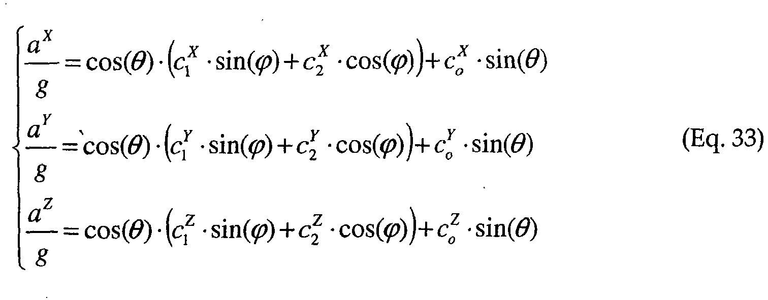
- For
ideal accelerometers 36 with ideal placements ψzy = 0, Eq. 33 reduces to:
- Now referring to
FIG. 14 , a data reduction algorithm as shown correctsaccelerometer 36 readings for zero offset drift and angular velocity. Such an algorithm can be used by a zero drift compensator, including a processor, with aCSN device 10 as shown inFIG. 11 , for example. The zero drift compensator works by rotating theCSN device 10. A zero drift compensator can operate by enforcing a rule that the average of the measured value of g be equal to the know value of g at a given time. Alternatively, a zero drift compensator can operate by enforcing a rule that the strain readings of the strain gauges 40 follow the same angular dependence on the rotation of thestring 12 as the angular dependence recorded by theaccelerometers 36. Alternatively, a zero drift compensator can operate by enforcing a rule that the strain readings of the strain gauges 40 follow a same angular dependence as that measured by angular encoders placed on the drill string 18 (FIG. 1 ) orsensor string 12. - Because the zero offset of the accelerometers will drift and/or the
accelerometers 36 are mounted on a rotating article, a more accurate description of the accelerometer reading would be:


Equations 36 are subject to a consistency condition:


- Since ω is small and the value of cos(θ) ≈ 1, the value of ω is determined using:

- The necessity for any correction for cos(θ) ≠ 1 must be determined experimentally to evaluate when deviation from this approximation becomes significant for this application.
- Since the
accelerometers 36 have a zero offset that will change with time,equation 40 will not be satisfied for real measurements. The value of offsets OF1, OF2, OF3, are determined by the least square fit, i.e., by minimizing, as follows:
- Once the values of the offsets OF1, OF2, OF3 are determined, the rotation angle can be defined as:

- When values of the offsets OF1, OF2, OF3 are known, the values of offsets of
individual accelerometers 36 and the values of ϕi and cos(θi ) can be determined. - Now referring to
FIGs. 15-17 , each of which shows a universal jointangle measurement sensor 50, which is an alternative embodiment to the strain gaugedisplacement CSN device 10 embodiments discussed above in relation to, e.g.,FIGs. 2c and8 . As shown inFIG. 15 , the universal joint 50 can be cylindrical in shape to fit in a borehole 16 or tube and is comprised of twomembers 56 joined at two sets of opposingbendable flexures 54 such that the joint 50 may bend in all directions in any plane orthogonal to its length. Thebendable flexures 54 are radially positioned with respect to an imaginary center axis of theuniversal joint 50. Each one of the two sets ofbendable flexures 54 allows for flex in the joint 50 along one plane along the imaginary center axis. Each plane of flex is orthogonal to the other, thus allowing for flex in all directions around the imaginary center axis. The strain forces at thebendable flexures 54 are measured in much the same way as those on thestrain gauge detectors 40 of theCSN device 10 ofFIG. 8 usingdetectors 52. Spatial orientation of universal joint 50 relative to the vertical may be measured by atri-axial accelerometer 57 attached to the interior ofuniversal joint 50. - The universal joint 50 may be connected to a
middle centralizer 14b of aCSN device 10 as shown inFIG. 16 . Aspring 58 can be used to activate thecentralizer 14b (this will be explained in further detail below with reference toFIGs. 19-20b ). Theuniversal joint 50 andmiddle centralizer 14b are rigidly attached to each other and connected witharms 44 to leading and trailingcentralizers 14a and 14c. - As shown in
FIG. 17 , theuniversal joint 50, when located on aCSN device 10 for use as a downhole tool for survey and/or navigation, is positioned at or near amiddle centralizer 14b of threecentralizers 14. The twoouter centralizers 14a and 14c are connected to the universal joint 50 byarms 44, as shown inFIG. 17 , which may house electronics packages if desired. Theuniversal joint 50 includes strain gauges 52 (FIG. 15 ) to measure the movement of thejoint members 56 andarms 44. - As discussed above, the
CSN device 10 of the various embodiments is used for the survey ofboreholes 16 or passageways and navigation of downhole devices; the goal of the navigation algorithm (FIG. 6 ) is to determine relative positions of thecentralizers 14 of theCSN device 10 and to determine the borehole 16 location of theCSN device 10 based on that data. Now referring toFIG. 18 , which is a block diagram of the assembly of aCSN device 10, the first local coordinate system (#1) has coordinate vectors as follows:
accelerometers 57 and g is the Earth gravity constant. Given a local coordinate system (FIGs. 5a-5d ) with point of origin


arm 44, the orientation of axis would be:
- Referring again to
FIG. 5d , which shows the local coordinate system previously discussed above, the reading of strain gauges, e.g., 52 as shown inFIG. 15 , provide the angles ϑy , ϑz of theCSN device 10segment leading centralizer 14c position in the local coordinate system. Correspondingly, the origin of the next coordinate system and thenext centralizer 14b would be:
- The orientation of the next coordinate system will be defined by Eq. 46 where the new vectors are:

- Using Eq. 45 and 46, one can define the origin and the orientation of the
CSN device 10 portion in the unknown region of a borehole 16 in the first local coordinate system. After applying equations 45 and 46 to allCSN device 10segments 13, the location of theCSN device 10 portion in the unknown region of aborehole 16 is determined. The shape of theCSN device 10 is defined up to the accuracy of the strain gauges 40 or 52. The inclination of theCSN device 10 with respect to the vertical is defined within the accuracy of theaccelerometers CSN device 10 is not known. - Now referring to
FIGs. 19 ,20a , and20b , embodiments of centralizers for use withCSN devices 10 are shown. As previously discussed,centralizers 14 are used to accurately and repeatably position the metrology sensors 28 (FIG. 1 ) discussed above within aborehole 16. Additionally, thecentralizer 14 has a knownpivot point 60 that will not move axially relative to the metrology article to which it is attached. Thecentralizer 14 is configured to adapt straight line mechanisms to constrain thecentralizer 14pivot point 60 to axially remain in the same lateral plane. This mechanism, sometimes referred to as a "Scott Russell" or "Evan's" linkage, is composed of two links, 64 as shown inFIG. 19 , and 64a and 64b as shown inFIGs. 20a and20b . Theshorter link 64b ofFIGs. 20a and20b has a fixedpivot point 60b, while the longer link 64a has a pivot point 60a free to move axially along thetube housing 34. Thelinks 64a and 64b are joined at a pivot point 66, located half-way along the length of the long link 64a, while theshort link 64b is sized so that the distance from the fixedpoint 60b to the linked pivot 66 is one half the length of the long link 64a. - This
centralizer 14 mechanism is formed by placing aspring 68 behind the sliding pivot point 60a, which provides an outward forcing load on the free end of the long link 64a. This design can use roller bearings at pivot points, but alternatively they could be made by other means, such as with a flexure for tighter tolerances, or with pins in holes if looser tolerances are allowed. Aroller 62 is positioned at the end of the long link 64a to contact the borehole 16 wall. - According to this
centralizer 14 concept, all pivot points are axially in line with thepivot point 60b of theshort link 64b, and thus, at a known location on theCSN device 10. Additionally, this mechanism reduces the volume of thecentralizer 14.FIG. 19 shows acentralizer 14 embodiment with a double roller, fixedpivot point 60. This embodiment has two spring-loaded 68rollers 62 centered around a fixedpivot point 60.FIGs. 20a and20b have a single roller structure, also with a single fixedpivot point 60, but with one spring-loaded 68roller 62. - In an alternative embodiment of the invention, a device is utilized for canceling the effects of gravity on a mechanical beam to mitigate sag. As shown in
FIGs. 21a and 21b , using buoyancy to compensate for gravity-induced sag of a metrology beam of aCSN device 10 having a proximity-detector-based or angular-metrology-based displacement sensor string, accuracy of the survey or navigation can be improved. As shown inFIG. 21a , an angle measuring metrologysensor CSN device 10 can enclose thesensor string segments 13 within ahousing 34 containing a fluid 81. This fluid 81 provides buoyancy for thesegments 13, thus mitigating sag. Alternatively, as shown inFIG. 21b , a displacement measuring metrologysensor CSN device 10 can likewise encase itsstraight beam 31 within a fluid 81 filledhousing 34. In this way, sagging of thestraight beam 31 is mitigated and with it errors in displacement sensing by thecapacitor sensor 38 are prevented. - Various embodiments of the invention have been described above. Although this invention has been described with reference to these specific embodiments, the descriptions are intended to be illustrative of the invention and are not intended to be limiting. Various modifications and applications may occur to those skilled in the art without departing from the scope of the invention as defined in the appended claims.
Claims (17)
- A survey and navigation metrology device (10), comprising:at least one sensor string (12) segment (13);at least three centralizers (14);at least one metrology sensor (28); andat least one odometry sensor, wherein the at least three centralizers are for supporting said string segment, said at least three centralizers including a middle centralizer (14b) and at least two other centralizers (14b, 14c);the at least one metrology sensor is for measuring displacement of said string segment relative to said middle centralizer, and for generating metrology information corresponding to said displacement, said metrology sensor being associated with said middle centralizer and being located between said at least two other centralizers, and wherein said displacement of said string segment relative to said middle centralizer is caused by relative movement of said at least two other centralizers; andthe at least one odometry sensor is for generating odometry information for determining, together with said displacement information, the position of said sensor string segment.
- The survey and navigation metrology device of claim 1, wherein said metrology sensor is an angle detector (29).
- The survey and navigation metrology device of claim 2, wherein a first sensor string (12) segment (13) connects said first centralizer and said second centralizer, and a second sensor string (12) segment (13) connects said second centralizer and said third centralizer.
- The survey and navigation metrology device of claim 3, wherein the angle detector (28) is configured to measure the angle between the first sensor string segment (13) and the second sensor string segment (13).
- The survey and navigation metrology device of claim 1, wherein said metrology sensor (28) is configured to measure the displacement of a straight beam relative to one of said three centralizers.
- The survey and navigation metrology device of claim 1, wherein said metrology sensor is a strain detector (40).
- The survey and navigation metrology device of claim 6, wherein said strain detector (40) is positioned on a first bending beam (32) between a first centralizer and a second centralizer.
- The survey and navigation metrology device of claim 7, wherein said strain detector (40) comprises a first pair of strain gauges and a second pair of strain gauges.
- The survey and navigation metrology device of claim 8, wherein each of said first and second pairs of strain gauges comprises a first gauge at a first position (X1) on said first bending beam (32) and a second gauge at a second position (X2) on said first bending beam each of said pairs of gauges being on opposite sides of the circumference of said first bending beam.
- The survey and navigation metrology device of claim 7, further comprising a second strain detector (40) positioned on a second bending beam (32) between said second centralizer and a third centralizer.
- The survey and navigation metrology device of claim 7, further comprising an accelerometer (36).
- The survey and navigation metrology device of claim 1, wherein said metrology sensor includes an optical detector.
- The survey and navigation metrology device of claim 12, wherein said optical detector comprises a laser.
- The survey and navigation metrology device of claim 1, wherein said centralizers are each configured to position a portion of the metrology device in the geometrical center of a passageway through which said metrology device extends.
- The survey and navigation metrology device of claim 1, wherein said at least one metrology sensor comprises at least one angle detector (29) and at least one displacement detector (38).
- The survey and navigation metrology device of claim 1, wherein said at least one metrology sensor comprises at least one displacement detector (38) and at least one strain detector (40).
- The survey and navigation metrology device of claim 1, comprising a plurality of metrology sensors (28) and further comprising means for calculating a local coordinate system of said device.
Applications Claiming Priority (2)
| Application Number | Priority Date | Filing Date | Title |
|---|---|---|---|
| US63547704P | 2004-12-14 | 2004-12-14 | |
| PCT/US2005/045276 WO2006065923A2 (en) | 2004-12-14 | 2005-12-14 | Centralizer-based survey and navigation device and method |
Publications (3)
| Publication Number | Publication Date |
|---|---|
| EP1831502A2 EP1831502A2 (en) | 2007-09-12 |
| EP1831502A4 EP1831502A4 (en) | 2010-07-07 |
| EP1831502B1 true EP1831502B1 (en) | 2018-10-31 |
Family
ID=36588509
Family Applications (1)
| Application Number | Title | Priority Date | Filing Date |
|---|---|---|---|
| EP05854063.4A Not-in-force EP1831502B1 (en) | 2004-12-14 | 2005-12-14 | Centralizer-based survey and navigation device and method |
Country Status (5)
| Country | Link |
|---|---|
| US (2) | US7584808B2 (en) |
| EP (1) | EP1831502B1 (en) |
| JP (2) | JP5362994B2 (en) |
| CA (1) | CA2591691C (en) |
| WO (1) | WO2006065923A2 (en) |
Families Citing this family (57)
| Publication number | Priority date | Publication date | Assignee | Title |
|---|---|---|---|---|
| US7528946B2 (en) * | 2003-03-31 | 2009-05-05 | The Charles Machine Works, Inc. | System for detecting deflection of a boring tool |
| US8396565B2 (en) | 2003-09-15 | 2013-03-12 | Medtronic, Inc. | Automatic therapy adjustments |
| US7957809B2 (en) | 2005-12-02 | 2011-06-07 | Medtronic, Inc. | Closed-loop therapy adjustment |
| US20090207302A1 (en) * | 2008-02-14 | 2009-08-20 | Chris Neffendorf | Method and apparatus to measure features in a conduit |
| US7823661B2 (en) * | 2008-06-24 | 2010-11-02 | Mintchev Martin P | In-drilling alignment |
| US9050471B2 (en) | 2008-07-11 | 2015-06-09 | Medtronic, Inc. | Posture state display on medical device user interface |
| US8209028B2 (en) | 2008-07-11 | 2012-06-26 | Medtronic, Inc. | Objectification of posture state-responsive therapy based on patient therapy adjustments |
| US8886302B2 (en) | 2008-07-11 | 2014-11-11 | Medtronic, Inc. | Adjustment of posture-responsive therapy |
| US8708934B2 (en) | 2008-07-11 | 2014-04-29 | Medtronic, Inc. | Reorientation of patient posture states for posture-responsive therapy |
| US8504150B2 (en) | 2008-07-11 | 2013-08-06 | Medtronic, Inc. | Associating therapy adjustments with posture states using a stability timer |
| US8249718B2 (en) | 2008-07-11 | 2012-08-21 | Medtronic, Inc. | Programming posture state-responsive therapy with nominal therapy parameters |
| US8219206B2 (en) | 2008-07-11 | 2012-07-10 | Medtronic, Inc. | Dwell time adjustments for posture state-responsive therapy |
| US9592387B2 (en) | 2008-07-11 | 2017-03-14 | Medtronic, Inc. | Patient-defined posture states for posture responsive therapy |
| US9440084B2 (en) | 2008-07-11 | 2016-09-13 | Medtronic, Inc. | Programming posture responsive therapy |
| US8280517B2 (en) | 2008-09-19 | 2012-10-02 | Medtronic, Inc. | Automatic validation techniques for validating operation of medical devices |
| US9327070B2 (en) | 2009-04-30 | 2016-05-03 | Medtronic, Inc. | Medical device therapy based on posture and timing |
| US8175720B2 (en) | 2009-04-30 | 2012-05-08 | Medtronic, Inc. | Posture-responsive therapy control based on patient input |
| US9026223B2 (en) | 2009-04-30 | 2015-05-05 | Medtronic, Inc. | Therapy system including multiple posture sensors |
| US9956418B2 (en) | 2010-01-08 | 2018-05-01 | Medtronic, Inc. | Graphical manipulation of posture zones for posture-responsive therapy |
| US9357949B2 (en) | 2010-01-08 | 2016-06-07 | Medtronic, Inc. | User interface that displays medical therapy and posture data |
| US8579834B2 (en) | 2010-01-08 | 2013-11-12 | Medtronic, Inc. | Display of detected patient posture state |
| US8388555B2 (en) | 2010-01-08 | 2013-03-05 | Medtronic, Inc. | Posture state classification for a medical device |
| CN102141197B (en) * | 2010-01-28 | 2013-03-20 | 杨志雄 | Measuring equipment for exploring path direction in pipe |
| US9566441B2 (en) | 2010-04-30 | 2017-02-14 | Medtronic, Inc. | Detecting posture sensor signal shift or drift in medical devices |
| US9803426B2 (en) * | 2010-06-18 | 2017-10-31 | Schlumberger Technology Corporation | Flex joint for downhole drilling applications |
| US8833183B2 (en) * | 2010-06-21 | 2014-09-16 | The Charles Machine Works, Inc. | Method and system for monitoring bend and torque forces on a drill pipe |
| US10060807B2 (en) | 2010-06-21 | 2018-08-28 | The Charles Machine Works, Inc. | Method and system for monitoring bend and torque forces on a drill pipe |
| US9181791B2 (en) | 2011-06-28 | 2015-11-10 | Raytheon Company | System and method for determining soil characteristics and drillstring instability during horizontal directional drilling |
| US9907959B2 (en) | 2012-04-12 | 2018-03-06 | Medtronic, Inc. | Velocity detection for posture-responsive therapy |
| US9737719B2 (en) | 2012-04-26 | 2017-08-22 | Medtronic, Inc. | Adjustment of therapy based on acceleration |
| KR102056898B1 (en) * | 2013-01-22 | 2019-12-18 | 삼성디스플레이 주식회사 | Flexible display and method for measuring angle of the same |
| US20140284103A1 (en) * | 2013-03-25 | 2014-09-25 | Schlumberger Technology Corporation | Monitoring System for Drilling Instruments |
| CA2815199A1 (en) * | 2013-05-02 | 2014-11-02 | 059312 N.B. Inc. | Cyclical sensor array |
| CA2815195A1 (en) * | 2013-05-02 | 2014-11-02 | 059312 N.B. Inc. | Bipartite sensor array |
| WO2015102600A1 (en) * | 2013-12-31 | 2015-07-09 | Halliburton Energy Services, Inc. | Bend measurements of adjustable motor assemblies using strain gauges |
| WO2015102602A1 (en) * | 2013-12-31 | 2015-07-09 | Halliburton Energy Services, Inc. | Bend measurements of adjustable motor assemblies using inclinometers |
| US9995133B2 (en) | 2013-12-31 | 2018-06-12 | Halliburton Energy Services, Inc. | Bend measurements of adjustable motor assemblies using magnetometers |
| RU2560762C1 (en) * | 2014-07-23 | 2015-08-20 | Федеральное Государственное Автономное Образовательное Учреждение Высшего Профессионального Образования "Сибирский Федеральный Университет" | Simulator for determination of direction of collared blastholes with reference to bottomhole plane |
| US10094211B2 (en) * | 2014-10-09 | 2018-10-09 | Schlumberger Technology Corporation | Methods for estimating wellbore gauge and dogleg severity |
| AU2015234298B2 (en) * | 2014-10-16 | 2020-07-02 | Imdex Technologies Pty Ltd | Controlled rotation centraliser |
| WO2016160013A1 (en) * | 2015-04-01 | 2016-10-06 | Halliburton Energy Services, Inc. | Determining the optimal radius of a thrust bearing in a well tool |
| JP6311650B2 (en) * | 2015-06-01 | 2018-04-18 | 住友金属鉱山株式会社 | Grout work simulation device, grout work simulation program, and grout method |
| US10626675B2 (en) | 2015-11-18 | 2020-04-21 | Tony Ross | Bearing section for a positive displacement mud motor for use in directional earth drilling |
| GB2545914A (en) * | 2015-12-30 | 2017-07-05 | Huyton Stuart | Adjustable roller centralizer |
| WO2017181396A1 (en) * | 2016-04-21 | 2017-10-26 | 深圳市樊溪电子有限公司 | Method for calculating bending strain of pipe |
| CN106950070B (en) * | 2017-03-06 | 2019-06-28 | 河海大学 | Experimental rig for rectangular top pipe jacking construction Whole Process Simulation |
| RU173657U1 (en) * | 2017-04-25 | 2017-09-05 | Егор Александрович Жильцов | Self-centering axis positioning device |
| US11131167B1 (en) | 2017-11-10 | 2021-09-28 | National Technology & Engineering Solutions Of Sandia, Llc | Modular anti-rotation drilling systems and methods |
| CN110485468B (en) * | 2019-08-08 | 2021-04-16 | 南方工程检测修复技术研究院 | Permanent circular working well with water-rich stratum preset jacking pipe door opening and construction method thereof |
| CN110485469B (en) * | 2019-08-08 | 2021-05-04 | 南方工程检测修复技术研究院 | Assembled recyclable circular working well with integrated rear wall and construction method thereof |
| CN110485470B (en) * | 2019-08-08 | 2021-05-04 | 郑州安源工程技术有限公司 | Rectangular working well with pre-arranged jacking pipe door opening and sliding type rear wall in water-rich stratum and construction method of rectangular working well |
| CN110485467B (en) * | 2019-08-08 | 2021-05-04 | 郑州安源工程技术有限公司 | Assembled recyclable rectangular working well with preset detachable door opening and sliding type rear wall and construction method thereof |
| CN110485466B (en) * | 2019-08-08 | 2021-04-20 | 南方工程检测修复技术研究院 | Assembly type recyclable circular working pit with reserved door opening and construction method thereof |
| CN110485471B (en) * | 2019-08-08 | 2021-05-04 | 郑州安源工程技术有限公司 | Sliding type rear wall integrated assembly type recyclable rectangular working well and construction method thereof |
| CN110886606B (en) * | 2019-11-20 | 2021-09-14 | 中国地质大学(北京) | Characteristic quantity-while-drilling assisted inertial inclinometry method and device |
| CN113202456B (en) * | 2021-04-21 | 2023-10-31 | 中煤科工集团西安研究院有限公司 | Underground coal mine tapping angle measuring device and method based on image processing |
| CN116856866B (en) * | 2023-09-01 | 2023-12-15 | 新疆坤隆石油装备有限公司 | Eccentric wear prevention device and method for sucker rod |
Family Cites Families (17)
| Publication number | Priority date | Publication date | Assignee | Title |
|---|---|---|---|---|
| US2100418A (en) * | 1937-06-12 | 1937-11-30 | Shell Dev | Orienting device for borehole deflecting tools |
| US4399692A (en) * | 1981-01-13 | 1983-08-23 | Sundstrand Data Control Group | Borehole survey apparatus utilizing accelerometers and probe joint measurements |
| JPS611791A (en) * | 1984-06-15 | 1986-01-07 | 鹿島建設株式会社 | Bore bending measurement of drilled bore by auger boring |
| US4629012A (en) * | 1985-07-08 | 1986-12-16 | Atlantic Richfield Company | Drainhole drilling assembly |
| US4823125A (en) * | 1987-06-30 | 1989-04-18 | Develco, Inc. | Method and apparatus for stabilizing a communication sensor in a borehole |
| US5193628A (en) * | 1991-06-03 | 1993-03-16 | Utd Incorporated | Method and apparatus for determining path orientation of a passageway |
| GB9204910D0 (en) * | 1992-03-05 | 1992-04-22 | Ledge 101 Ltd | Downhole tool |
| US5758723A (en) * | 1996-06-05 | 1998-06-02 | Tiw Corporation | Fluid pressure deactivated thru-tubing centralizer |
| US5947213A (en) | 1996-12-02 | 1999-09-07 | Intelligent Inspection Corporation | Downhole tools using artificial intelligence based control |
| JP3554929B2 (en) * | 2000-05-09 | 2004-08-18 | 韓国科学技術院 | Swing-arm optical system for measuring 6-DOF motion of hard disk drive slider using multi-directional reflector |
| US6536531B2 (en) * | 2000-07-10 | 2003-03-25 | Weatherford/Lamb, Inc. | Apparatus and methods for orientation of a tubular string in a non-vertical wellbore |
| US6742604B2 (en) * | 2002-03-29 | 2004-06-01 | Schlumberger Technology Corporation | Rotary control of rotary steerables using servo-accelerometers |
| US6910533B2 (en) * | 2002-04-02 | 2005-06-28 | Schlumberger Technology Corporation | Mechanism that assists tractoring on uniform and non-uniform surfaces |
| US6820716B2 (en) * | 2003-01-16 | 2004-11-23 | Baker Hughes Incorporated | Acoustic isolator for well logging system |
| US7185715B2 (en) * | 2003-03-10 | 2007-03-06 | Baker Hughes Incorporated | Apparatus and method of controlling motion and vibration of an NMR sensor in a drilling bha |
| US20050241835A1 (en) * | 2004-05-03 | 2005-11-03 | Halliburton Energy Services, Inc. | Self-activating downhole tool |
| US7243719B2 (en) * | 2004-06-07 | 2007-07-17 | Pathfinder Energy Services, Inc. | Control method for downhole steering tool |
-
2005
- 2005-12-14 US US11/302,384 patent/US7584808B2/en active Active
- 2005-12-14 EP EP05854063.4A patent/EP1831502B1/en not_active Not-in-force
- 2005-12-14 CA CA2591691A patent/CA2591691C/en not_active Expired - Fee Related
- 2005-12-14 JP JP2007546864A patent/JP5362994B2/en active Active
- 2005-12-14 WO PCT/US2005/045276 patent/WO2006065923A2/en active Application Filing
-
2009
- 2009-08-17 US US12/542,529 patent/US7870912B2/en active Active
-
2011
- 2011-12-09 JP JP2011270671A patent/JP5726059B2/en active Active
Non-Patent Citations (1)
| Title |
|---|
| None * |
Also Published As
| Publication number | Publication date |
|---|---|
| WO2006065923A3 (en) | 2009-04-09 |
| US7584808B2 (en) | 2009-09-08 |
| EP1831502A2 (en) | 2007-09-12 |
| JP5362994B2 (en) | 2013-12-11 |
| WO2006065923A2 (en) | 2006-06-22 |
| EP1831502A4 (en) | 2010-07-07 |
| JP5726059B2 (en) | 2015-05-27 |
| JP2008525762A (en) | 2008-07-17 |
| CA2591691A1 (en) | 2006-06-22 |
| CA2591691C (en) | 2014-07-29 |
| US20100038068A1 (en) | 2010-02-18 |
| US20060157278A1 (en) | 2006-07-20 |
| US7870912B2 (en) | 2011-01-18 |
| JP2012083360A (en) | 2012-04-26 |
Similar Documents
| Publication | Publication Date | Title |
|---|---|---|
| EP1831502B1 (en) | Centralizer-based survey and navigation device and method | |
| CA2110060C (en) | Method and apparatus for determining path orientation of a passageway | |
| US8185312B2 (en) | Downhole surveying utilizing multiple measurements | |
| US7789171B2 (en) | Device and method for measuring a property in a downhole apparatus | |
| US8095317B2 (en) | Downhole surveying utilizing multiple measurements | |
| EP2694914B1 (en) | Method and apparatus for determining orientation using a plurality of angular rate sensors and accelerometers | |
| US9777568B2 (en) | Bipartite sensor array | |
| BR112013003751B1 (en) | system and method of measuring directional characteristics of a downhole tool | |
| JPS6015883B2 (en) | Borehole surveying device | |
| CA2291545C (en) | Method and apparatus for use in creating a magnetic declination profile for a borehole | |
| BR112014020851B1 (en) | APPARATUS AND METHOD FOR ESTIMATING THE PROBING HOLE DEPTH | |
| AU2012318276B8 (en) | Navigation device and method for surveying and directing a borehole under drilling conditions |
Legal Events
| Date | Code | Title | Description |
|---|---|---|---|
| PUAI | Public reference made under article 153(3) epc to a published international application that has entered the european phase |
Free format text: ORIGINAL CODE: 0009012 |
|
| 17P | Request for examination filed |
Effective date: 20070705 |
|
| AK | Designated contracting states |
Kind code of ref document: A2 Designated state(s): AT BE BG CH CY CZ DE DK EE ES FI FR GB GR HU IE IS IT LI LT LU LV MC NL PL PT RO SE SI SK TR |
|
| AX | Request for extension of the european patent |
Extension state: AL BA HR MK YU |
|
| DAX | Request for extension of the european patent (deleted) | ||
| R17D | Deferred search report published (corrected) |
Effective date: 20090409 |
|
| A4 | Supplementary search report drawn up and despatched |
Effective date: 20100607 |
|
| RIC1 | Information provided on ipc code assigned before grant |
Ipc: E21B 47/02 20060101AFI20060626BHEP Ipc: E21B 17/10 20060101ALI20100531BHEP Ipc: G01V 11/00 20060101ALI20100531BHEP |
|
| 17Q | First examination report despatched |
Effective date: 20110301 |
|
| RAP1 | Party data changed (applicant data changed or rights of an application transferred) |
Owner name: RAYTHEON COMPANY |
|
| GRAP | Despatch of communication of intention to grant a patent |
Free format text: ORIGINAL CODE: EPIDOSNIGR1 |
|
| STAA | Information on the status of an ep patent application or granted ep patent |
Free format text: STATUS: GRANT OF PATENT IS INTENDED |
|
| INTG | Intention to grant announced |
Effective date: 20171106 |
|
| GRAJ | Information related to disapproval of communication of intention to grant by the applicant or resumption of examination proceedings by the epo deleted |
Free format text: ORIGINAL CODE: EPIDOSDIGR1 |
|
| STAA | Information on the status of an ep patent application or granted ep patent |
Free format text: STATUS: EXAMINATION IS IN PROGRESS |
|
| INTC | Intention to grant announced (deleted) | ||
| GRAP | Despatch of communication of intention to grant a patent |
Free format text: ORIGINAL CODE: EPIDOSNIGR1 |
|
| STAA | Information on the status of an ep patent application or granted ep patent |
Free format text: STATUS: GRANT OF PATENT IS INTENDED |
|
| INTG | Intention to grant announced |
Effective date: 20180509 |
|
| GRAS | Grant fee paid |
Free format text: ORIGINAL CODE: EPIDOSNIGR3 |
|
| GRAA | (expected) grant |
Free format text: ORIGINAL CODE: 0009210 |
|
| STAA | Information on the status of an ep patent application or granted ep patent |
Free format text: STATUS: THE PATENT HAS BEEN GRANTED |
|
| AK | Designated contracting states |
Kind code of ref document: B1 Designated state(s): AT BE BG CH CY CZ DE DK EE ES FI FR GB GR HU IE IS IT LI LT LU LV MC NL PL PT RO SE SI SK TR |
|
| REG | Reference to a national code |
Ref country code: CH Ref legal event code: EP Ref country code: GB Ref legal event code: FG4D |
|
| REG | Reference to a national code |
Ref country code: AT Ref legal event code: REF Ref document number: 1059630 Country of ref document: AT Kind code of ref document: T Effective date: 20181115 |
|
| REG | Reference to a national code |
Ref country code: DE Ref legal event code: R096 Ref document number: 602005054919 Country of ref document: DE |
|
| REG | Reference to a national code |
Ref country code: IE Ref legal event code: FG4D |
|
| REG | Reference to a national code |
Ref country code: NL Ref legal event code: MP Effective date: 20181031 |
|
| REG | Reference to a national code |
Ref country code: LT Ref legal event code: MG4D |
|
| REG | Reference to a national code |
Ref country code: AT Ref legal event code: MK05 Ref document number: 1059630 Country of ref document: AT Kind code of ref document: T Effective date: 20181031 |
|
| PG25 | Lapsed in a contracting state [announced via postgrant information from national office to epo] |
Ref country code: ES Free format text: LAPSE BECAUSE OF FAILURE TO SUBMIT A TRANSLATION OF THE DESCRIPTION OR TO PAY THE FEE WITHIN THE PRESCRIBED TIME-LIMIT Effective date: 20181031 Ref country code: LV Free format text: LAPSE BECAUSE OF FAILURE TO SUBMIT A TRANSLATION OF THE DESCRIPTION OR TO PAY THE FEE WITHIN THE PRESCRIBED TIME-LIMIT Effective date: 20181031 Ref country code: PL Free format text: LAPSE BECAUSE OF FAILURE TO SUBMIT A TRANSLATION OF THE DESCRIPTION OR TO PAY THE FEE WITHIN THE PRESCRIBED TIME-LIMIT Effective date: 20181031 Ref country code: LT Free format text: LAPSE BECAUSE OF FAILURE TO SUBMIT A TRANSLATION OF THE DESCRIPTION OR TO PAY THE FEE WITHIN THE PRESCRIBED TIME-LIMIT Effective date: 20181031 Ref country code: BG Free format text: LAPSE BECAUSE OF FAILURE TO SUBMIT A TRANSLATION OF THE DESCRIPTION OR TO PAY THE FEE WITHIN THE PRESCRIBED TIME-LIMIT Effective date: 20190131 Ref country code: FI Free format text: LAPSE BECAUSE OF FAILURE TO SUBMIT A TRANSLATION OF THE DESCRIPTION OR TO PAY THE FEE WITHIN THE PRESCRIBED TIME-LIMIT Effective date: 20181031 Ref country code: AT Free format text: LAPSE BECAUSE OF FAILURE TO SUBMIT A TRANSLATION OF THE DESCRIPTION OR TO PAY THE FEE WITHIN THE PRESCRIBED TIME-LIMIT Effective date: 20181031 Ref country code: IS Free format text: LAPSE BECAUSE OF FAILURE TO SUBMIT A TRANSLATION OF THE DESCRIPTION OR TO PAY THE FEE WITHIN THE PRESCRIBED TIME-LIMIT Effective date: 20190228 |
|
| PGFP | Annual fee paid to national office [announced via postgrant information from national office to epo] |
Ref country code: FR Payment date: 20190125 Year of fee payment: 15 Ref country code: DE Payment date: 20190115 Year of fee payment: 14 |
|
| PG25 | Lapsed in a contracting state [announced via postgrant information from national office to epo] |
Ref country code: SE Free format text: LAPSE BECAUSE OF FAILURE TO SUBMIT A TRANSLATION OF THE DESCRIPTION OR TO PAY THE FEE WITHIN THE PRESCRIBED TIME-LIMIT Effective date: 20181031 Ref country code: GR Free format text: LAPSE BECAUSE OF FAILURE TO SUBMIT A TRANSLATION OF THE DESCRIPTION OR TO PAY THE FEE WITHIN THE PRESCRIBED TIME-LIMIT Effective date: 20190201 Ref country code: NL Free format text: LAPSE BECAUSE OF FAILURE TO SUBMIT A TRANSLATION OF THE DESCRIPTION OR TO PAY THE FEE WITHIN THE PRESCRIBED TIME-LIMIT Effective date: 20181031 Ref country code: PT Free format text: LAPSE BECAUSE OF FAILURE TO SUBMIT A TRANSLATION OF THE DESCRIPTION OR TO PAY THE FEE WITHIN THE PRESCRIBED TIME-LIMIT Effective date: 20190301 |
|
| PG25 | Lapsed in a contracting state [announced via postgrant information from national office to epo] |
Ref country code: CZ Free format text: LAPSE BECAUSE OF FAILURE TO SUBMIT A TRANSLATION OF THE DESCRIPTION OR TO PAY THE FEE WITHIN THE PRESCRIBED TIME-LIMIT Effective date: 20181031 Ref country code: IT Free format text: LAPSE BECAUSE OF FAILURE TO SUBMIT A TRANSLATION OF THE DESCRIPTION OR TO PAY THE FEE WITHIN THE PRESCRIBED TIME-LIMIT Effective date: 20181031 Ref country code: DK Free format text: LAPSE BECAUSE OF FAILURE TO SUBMIT A TRANSLATION OF THE DESCRIPTION OR TO PAY THE FEE WITHIN THE PRESCRIBED TIME-LIMIT Effective date: 20181031 |
|
| REG | Reference to a national code |
Ref country code: CH Ref legal event code: PL |
|
| REG | Reference to a national code |
Ref country code: DE Ref legal event code: R097 Ref document number: 602005054919 Country of ref document: DE |
|
| PG25 | Lapsed in a contracting state [announced via postgrant information from national office to epo] |
Ref country code: SK Free format text: LAPSE BECAUSE OF FAILURE TO SUBMIT A TRANSLATION OF THE DESCRIPTION OR TO PAY THE FEE WITHIN THE PRESCRIBED TIME-LIMIT Effective date: 20181031 Ref country code: MC Free format text: LAPSE BECAUSE OF FAILURE TO SUBMIT A TRANSLATION OF THE DESCRIPTION OR TO PAY THE FEE WITHIN THE PRESCRIBED TIME-LIMIT Effective date: 20181031 Ref country code: LU Free format text: LAPSE BECAUSE OF NON-PAYMENT OF DUE FEES Effective date: 20181214 Ref country code: RO Free format text: LAPSE BECAUSE OF FAILURE TO SUBMIT A TRANSLATION OF THE DESCRIPTION OR TO PAY THE FEE WITHIN THE PRESCRIBED TIME-LIMIT Effective date: 20181031 Ref country code: EE Free format text: LAPSE BECAUSE OF FAILURE TO SUBMIT A TRANSLATION OF THE DESCRIPTION OR TO PAY THE FEE WITHIN THE PRESCRIBED TIME-LIMIT Effective date: 20181031 |
|
| PLBE | No opposition filed within time limit |
Free format text: ORIGINAL CODE: 0009261 |
|
| STAA | Information on the status of an ep patent application or granted ep patent |
Free format text: STATUS: NO OPPOSITION FILED WITHIN TIME LIMIT |
|
| REG | Reference to a national code |
Ref country code: IE Ref legal event code: MM4A |
|
| GBPC | Gb: european patent ceased through non-payment of renewal fee |
Effective date: 20190131 |
|
| REG | Reference to a national code |
Ref country code: BE Ref legal event code: MM Effective date: 20181231 |
|
| 26N | No opposition filed |
Effective date: 20190801 |
|
| PG25 | Lapsed in a contracting state [announced via postgrant information from national office to epo] |
Ref country code: IE Free format text: LAPSE BECAUSE OF NON-PAYMENT OF DUE FEES Effective date: 20181214 Ref country code: SI Free format text: LAPSE BECAUSE OF FAILURE TO SUBMIT A TRANSLATION OF THE DESCRIPTION OR TO PAY THE FEE WITHIN THE PRESCRIBED TIME-LIMIT Effective date: 20181031 |
|
| PG25 | Lapsed in a contracting state [announced via postgrant information from national office to epo] |
Ref country code: BE Free format text: LAPSE BECAUSE OF NON-PAYMENT OF DUE FEES Effective date: 20181231 |
|
| PG25 | Lapsed in a contracting state [announced via postgrant information from national office to epo] |
Ref country code: LI Free format text: LAPSE BECAUSE OF NON-PAYMENT OF DUE FEES Effective date: 20181231 Ref country code: GB Free format text: LAPSE BECAUSE OF NON-PAYMENT OF DUE FEES Effective date: 20190131 Ref country code: CH Free format text: LAPSE BECAUSE OF NON-PAYMENT OF DUE FEES Effective date: 20181231 |
|
| PG25 | Lapsed in a contracting state [announced via postgrant information from national office to epo] |
Ref country code: TR Free format text: LAPSE BECAUSE OF FAILURE TO SUBMIT A TRANSLATION OF THE DESCRIPTION OR TO PAY THE FEE WITHIN THE PRESCRIBED TIME-LIMIT Effective date: 20181031 |
|
| PG25 | Lapsed in a contracting state [announced via postgrant information from national office to epo] |
Ref country code: HU Free format text: LAPSE BECAUSE OF FAILURE TO SUBMIT A TRANSLATION OF THE DESCRIPTION OR TO PAY THE FEE WITHIN THE PRESCRIBED TIME-LIMIT; INVALID AB INITIO Effective date: 20051214 Ref country code: CY Free format text: LAPSE BECAUSE OF FAILURE TO SUBMIT A TRANSLATION OF THE DESCRIPTION OR TO PAY THE FEE WITHIN THE PRESCRIBED TIME-LIMIT Effective date: 20181031 |
|
| REG | Reference to a national code |
Ref country code: DE Ref legal event code: R119 Ref document number: 602005054919 Country of ref document: DE |
|
| PG25 | Lapsed in a contracting state [announced via postgrant information from national office to epo] |
Ref country code: DE Free format text: LAPSE BECAUSE OF NON-PAYMENT OF DUE FEES Effective date: 20200701 |
|
| PG25 | Lapsed in a contracting state [announced via postgrant information from national office to epo] |
Ref country code: FR Free format text: LAPSE BECAUSE OF NON-PAYMENT OF DUE FEES Effective date: 20201231 |