EP1830428A2 - A recovery unit for a fuel cell and method of controlling same - Google Patents
A recovery unit for a fuel cell and method of controlling same Download PDFInfo
- Publication number
- EP1830428A2 EP1830428A2 EP07103438A EP07103438A EP1830428A2 EP 1830428 A2 EP1830428 A2 EP 1830428A2 EP 07103438 A EP07103438 A EP 07103438A EP 07103438 A EP07103438 A EP 07103438A EP 1830428 A2 EP1830428 A2 EP 1830428A2
- Authority
- EP
- European Patent Office
- Prior art keywords
- fuel
- housing
- valve
- recovery unit
- pipe
- Prior art date
- Legal status (The legal status is an assumption and is not a legal conclusion. Google has not performed a legal analysis and makes no representation as to the accuracy of the status listed.)
- Granted
Links
Images

Classifications
-
- B—PERFORMING OPERATIONS; TRANSPORTING
- B05—SPRAYING OR ATOMISING IN GENERAL; APPLYING FLUENT MATERIALS TO SURFACES, IN GENERAL
- B05B—SPRAYING APPARATUS; ATOMISING APPARATUS; NOZZLES
- B05B1/00—Nozzles, spray heads or other outlets, with or without auxiliary devices such as valves, heating means
- B05B1/14—Nozzles, spray heads or other outlets, with or without auxiliary devices such as valves, heating means with multiple outlet openings; with strainers in or outside the outlet opening
- B05B1/18—Roses; Shower heads
-
- H—ELECTRICITY
- H01—ELECTRIC ELEMENTS
- H01M—PROCESSES OR MEANS, e.g. BATTERIES, FOR THE DIRECT CONVERSION OF CHEMICAL ENERGY INTO ELECTRICAL ENERGY
- H01M8/00—Fuel cells; Manufacture thereof
- H01M8/04—Auxiliary arrangements, e.g. for control of pressure or for circulation of fluids
- H01M8/04082—Arrangements for control of reactant parameters, e.g. pressure or concentration
- H01M8/04089—Arrangements for control of reactant parameters, e.g. pressure or concentration of gaseous reactants
- H01M8/04097—Arrangements for control of reactant parameters, e.g. pressure or concentration of gaseous reactants with recycling of the reactants
-
- H—ELECTRICITY
- H01—ELECTRIC ELEMENTS
- H01M—PROCESSES OR MEANS, e.g. BATTERIES, FOR THE DIRECT CONVERSION OF CHEMICAL ENERGY INTO ELECTRICAL ENERGY
- H01M8/00—Fuel cells; Manufacture thereof
- H01M8/04—Auxiliary arrangements, e.g. for control of pressure or for circulation of fluids
- H01M8/04082—Arrangements for control of reactant parameters, e.g. pressure or concentration
- H01M8/04201—Reactant storage and supply, e.g. means for feeding, pipes
-
- H—ELECTRICITY
- H01—ELECTRIC ELEMENTS
- H01M—PROCESSES OR MEANS, e.g. BATTERIES, FOR THE DIRECT CONVERSION OF CHEMICAL ENERGY INTO ELECTRICAL ENERGY
- H01M8/00—Fuel cells; Manufacture thereof
- H01M8/04—Auxiliary arrangements, e.g. for control of pressure or for circulation of fluids
- H01M8/04291—Arrangements for managing water in solid electrolyte fuel cell systems
-
- H—ELECTRICITY
- H01—ELECTRIC ELEMENTS
- H01M—PROCESSES OR MEANS, e.g. BATTERIES, FOR THE DIRECT CONVERSION OF CHEMICAL ENERGY INTO ELECTRICAL ENERGY
- H01M8/00—Fuel cells; Manufacture thereof
- H01M8/04—Auxiliary arrangements, e.g. for control of pressure or for circulation of fluids
- H01M8/04082—Arrangements for control of reactant parameters, e.g. pressure or concentration
- H01M8/04089—Arrangements for control of reactant parameters, e.g. pressure or concentration of gaseous reactants
- H01M8/04119—Arrangements for control of reactant parameters, e.g. pressure or concentration of gaseous reactants with simultaneous supply or evacuation of electrolyte; Humidifying or dehumidifying
- H01M8/04126—Humidifying
- H01M8/04141—Humidifying by water containing exhaust gases
-
- H—ELECTRICITY
- H01—ELECTRIC ELEMENTS
- H01M—PROCESSES OR MEANS, e.g. BATTERIES, FOR THE DIRECT CONVERSION OF CHEMICAL ENERGY INTO ELECTRICAL ENERGY
- H01M8/00—Fuel cells; Manufacture thereof
- H01M8/04—Auxiliary arrangements, e.g. for control of pressure or for circulation of fluids
- H01M8/04082—Arrangements for control of reactant parameters, e.g. pressure or concentration
- H01M8/04089—Arrangements for control of reactant parameters, e.g. pressure or concentration of gaseous reactants
- H01M8/04119—Arrangements for control of reactant parameters, e.g. pressure or concentration of gaseous reactants with simultaneous supply or evacuation of electrolyte; Humidifying or dehumidifying
- H01M8/04156—Arrangements for control of reactant parameters, e.g. pressure or concentration of gaseous reactants with simultaneous supply or evacuation of electrolyte; Humidifying or dehumidifying with product water removal
- H01M8/04164—Arrangements for control of reactant parameters, e.g. pressure or concentration of gaseous reactants with simultaneous supply or evacuation of electrolyte; Humidifying or dehumidifying with product water removal by condensers, gas-liquid separators or filters
-
- H—ELECTRICITY
- H01—ELECTRIC ELEMENTS
- H01M—PROCESSES OR MEANS, e.g. BATTERIES, FOR THE DIRECT CONVERSION OF CHEMICAL ENERGY INTO ELECTRICAL ENERGY
- H01M8/00—Fuel cells; Manufacture thereof
- H01M8/10—Fuel cells with solid electrolytes
- H01M8/1009—Fuel cells with solid electrolytes with one of the reactants being liquid, solid or liquid-charged
- H01M8/1011—Direct alcohol fuel cells [DAFC], e.g. direct methanol fuel cells [DMFC]
-
- Y—GENERAL TAGGING OF NEW TECHNOLOGICAL DEVELOPMENTS; GENERAL TAGGING OF CROSS-SECTIONAL TECHNOLOGIES SPANNING OVER SEVERAL SECTIONS OF THE IPC; TECHNICAL SUBJECTS COVERED BY FORMER USPC CROSS-REFERENCE ART COLLECTIONS [XRACs] AND DIGESTS
- Y02—TECHNOLOGIES OR APPLICATIONS FOR MITIGATION OR ADAPTATION AGAINST CLIMATE CHANGE
- Y02E—REDUCTION OF GREENHOUSE GAS [GHG] EMISSIONS, RELATED TO ENERGY GENERATION, TRANSMISSION OR DISTRIBUTION
- Y02E60/00—Enabling technologies; Technologies with a potential or indirect contribution to GHG emissions mitigation
- Y02E60/30—Hydrogen technology
- Y02E60/50—Fuel cells
Definitions
- the present invention relates to a recovery unit for a fuel cell and a method of driving the same, in which the recovering unit recovers gas, water and unreacted fuel produced in an electric generator of a fuel cell system and discharges the gas and recycles water and the unreacted fuel effectively.
- the invention also relates to a fuel cell incorporating the recovery unit according to the invention.
- a fuel cell is a power generating system that directly transforms chemical energy into electric energy by an electrochemical reaction between hydrogen and oxygen.
- pure hydrogen or hydrogen gained from methanol, ethanol, natural gas or the like can be directly used.
- oxygen can be directly used, or oxygen contained in air can be supplied by an air pump or the like.
- One aspect of the present invention provides a fuel cell with a recovering unit and a method of driving the same, in which gas recovered from an electric generator of the fuel cell into a recovering container is prevented from flowing into an anode electrode or mixed fuel is prevented from flowing into a cathode electrode, additionally the mixed fuel stored in the recovering container is prevented from evaporating.
- Embodiments of the present invention are achieved by providing a fuel cell comprising: i) an electric generator to generate electricity based on oxidation of mixed fuel in an anode electrode and reduction of oxygen in a cathode electrode, ii) a fuel container to store raw fuel, iii) a recovering unit to recover and mix the raw fuel, unreacted fuel not participated in the oxidation of the electric generator, and water produced by the reduction to make the mixed fuel, and supply the mixed fuel to the electric generator and iv) an air feeder to supply oxygen to the electric generator, wherein the recovering unit comprises a housing connected to and communicating with the electric generator and the fuel container, a discharging pipe provided inside the housing to discharge gas recovered from the electric generator, and having a first end extending to the outside of the housing and a second end extending to the inside of the housing and a first valve provided in the discharging pipe.
- the recovering unit may further comprise a second valve provided in an anode recovering pipe which connects the housing with an outlet of the anode electrode of the electric generator to communicate with each other. Further, the recovering unit may comprise a third valve provided in a cathode recovering pipe which connects the housing with an outlet of the cathode electrode of the electric generator to communicate with each other. Also, the second valve and the third valve may comprise on/off valves or check valves.
- the second end of the discharging pipe connected to a float.
- the housing may comprise a porous material placed on an inner surface thereof and adjacent to the anode recovering pipe.
- Another aspect of the present invention provides a method of driving a fuel cell, comprising: i) supplying hydrogen containing mixed fuel and oxygen to an electric generator via a first supplying line and a second supplying line, ii) generating electricity by electrochemical reaction between hydrogen and oxygen in the electric generator, iii) recovering byproducts produced by the electrochemical reaction of the electric generator to a recovering unit via a recovering path, iv) discharging gas contained in the byproducts from the recovering unit to the air and v) mixing unreacted fuel contained in the byproducts, water and fuel into the hydrogen containing mixed fuel while discharging the gas to the air.
- a fuel cell is generally classified into i) a polymer electrolyte membrane fuel cell (PEMFC) and ii) a direct methanol fuel cell (DMFC), which operate at room temperature or a temperature of less than about 100°C, iii) a phosphoric acid fuel cell (PAFC) which operates at a temperature of about 150°C ⁇ about 200°C, iv) a molten carbon fuel cell (MCFC) which operates at a temperature of about 600°C ⁇ about 700°C , v) a solid oxide fuel cell (SOFC) which operates at a high temperature of more than about 1000°C , and so on.
- PEMFC polymer electrolyte membrane fuel cell
- DMFC direct methanol fuel cell
- PAFC phosphoric acid fuel cell
- MCFC molten carbon fuel cell
- SOFC solid oxide fuel cell
- the fuel cell can include a recovering container to recover the unreacted fuel, which has not participated in the electrochemical reaction of the anode electrode, and water, which is produced by the chemical reaction of the cathode electrode, in order to supply them to the electric generator again.
- the recovering container includes a discharging pipe to discharge unnecessary gas contained in the unreacted fuel.
- Such a recovering container is connected to and is in fluid communication with the electric generator. Therefore, when the fuel cell is maintained abnormally, for example, when the fuel cell is maintained inclined or reversed, the mixed fuel stored in the recovering container is likely to flow into the cathode electrode or the gas is likely to flow into the anode electrode.
- the mixed fuel stored in the recovering container due to high volatility, is continuously evaporated through the discharging pipe, thereby exhausting the fuel wastefully.
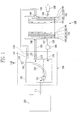
- FIG. 1 is a schematic view of a fuel cell system with a recovering unit according to an embodiment of the present invention.
- raw fuel is methanol, particularly, high concentration methanol
- mixed fuel or hydrogen containing mixed fuel is mixture of the raw fuel and water and/or unreacted fuel recovered from the electric generator.
- the fuel cell system includes a fuel container 110, a recovering unit (or a fuel provider) 130, an electric (or electricity) generator 140, and an air feeder (or an oxygen provider) 150.
- the raw fuel stored in the fuel container 110 is supplied to the recovering unit 130 through a fuel supplying pipe 111 connected to and communicating with the recovering unit 130.
- a fuel supplying pipe 111 connected to and communicating with the recovering unit 130.
- unreacted mixed fuel discharged from the electric generator 140, water and the raw fuel are mixed, thereby making the mixed fuel having a predetermined concentration.
- the mixed fuel flows along a mixed fuel supplying pipe 124 by a fuel pump 160, and is introduced into an anode electrode 142 of the electric generator 140 through an anode inlet 147.
- the recovering unit 130 will be described later in more detail.
- the electric generator 140 generates electricity by electrochemical reaction between hydrogen contained in the mixed fuel supplied from the recovering unit 130 and oxygen supplied from the air feeder 150.
- the electric generator 140 includes at least one unit cell to generate electric energy.
- the unit cell includes a membrane electrode assembly (MEA) 144 to oxidize the mixed fuel and reduce oxygen, and a separating plate 145 to supply the mixed fuel and oxygen to the membrane electrode assembly 144 and discharge products generated by the oxidation/reduction reaction in the membrane electrode assembly 144.
- the membrane electrode assembly 144 generally includes the anode electrode 142, the cathode electrode 143, and an electrolyte membrane 141 interposed between the anode electrode 142 and the cathode electrode 143. Further, the electric generator 140 has a stack structure in which a plurality of unit cells are stacked.
- channels (not shown) formed in one ore more separating plates 145 adjacent to the anode electrodes 142 are aligned in a row and communicate with one another.
- One ends of the aligned channels are communicated with the anode inlet 147 formed in one side of the electric generator 140, and the other ends are communicated with an anode outlet 146 formed in the other side of the electric generator 140.
- channels (not shown) formed in one or more separating plates 145 adjacent to the cathode electrodes 143 are aligned in a row and communicate with one another.
- One end of the aligned channels are communicated with the cathode inlet 149 formed in one side of the electric generator 140, and the other ends are communicated with an cathode outlet 148 formed in the other side of the electric generator 140.
- the mixed fuel is introduced through the anode inlet 147 of the electric generator 140 and supplied to the anode electrode 142 along the channel of the separating plate 145 adjacent to the anode electrode 142. Further, oxygen is introduced through the cathode inlet 149 of the electric generator 140 and supplied to the cathode electrode 143 through the channel of the separating plate 145 adjacent to the cathode electrode 143.
- reaction Formula 1 Anode: CH30H + H2O ⁇ CO2 + 6H+ + 6e- Cathode:3/2O2 + 6H+ + 6e- ⁇ 3H2O Total: CH3OH + 3/2O2 ⁇ CO2 + H2O
- gas such as carbon dioxide produced in the anode electrode 142 and the unreacted fuel which has not participated in the electrochemical reaction of the anode electrode, flow along the channel formed in the separating plate 145 adjacent to the anode electrode 142 and are discharged through the anode outlet 146.
- water produced in the cathode electrode 143 flows along the channel formed in the separating plate 145 adjacent to the cathode electrode 143 and is discharged through the cathode outlet 148.
- the fuel cell includes the recovering unit 130 to recover and recycle the unreacted mixed fuel discharged through the anode outlet 146 and water discharged through the cathode outlet 148.
- the recovering unit 130 has a housing 131 in which the unreacted mixed fuel, water, and the raw fuel supplied from the fuel container 110 are mixed.
- the anode outlet 146 of the electric generator and the housing 131 of the recovering unit 130 are connected to and communicate with each other through an anode recovering pipe 123, such that the gas such as carbon dioxide produced by the reaction in the anode electrode is introduced into the housing 131 of the recovering unit 130 through the anode recovering pipe 123 while the unreacted fuel from the anode outlet 146 is recovered into the housing 131.
- the cathode outlet 148 of the electric generator 140 and the housing 131 of the recovering unit 130 are connected to and communicate with each other through a cathode recovering pipe 121, such that water discharged from the cathode outlet 148 is introduced into the housing 131 of the recovering unit.
- the housing 131 of the recovering unit 130 includes a discharging pipe 132.
- the discharging pipe 132 has a first end extending to the outside of the housing 131 and provide with a first valve 133.
- the discharging pipe 132 has a second end extending to the inside of the housing 131 and penetrating a float 134.
- the second end of the discharging pipe 132 can be exposed to the gas contained in the housing 131 because of the float 134 irrespective of an inclined state of the housing 131. Therefore, the gas such as carbon dioxide or the like existing in the housing 131 of the recovering unit 130 is introduced into the second end of the discharging pipe 132 and discharged to the outside through the first end of the discharging pipe 132.
- the first valve 133 is opened and closed to control an opened state of the discharging pipe 132, thereby allowing fluid to pass through the discharging pipe 132 or stopping the fluid.
- the first valve 133 is opened while the fuel cell generates electricity, so that the gas such as carbon dioxide or the like flowing from the electric generator 140 to the housing 131 is discharged to the outside through the discharging pipe 132.
- the first valve 133 is closed when the fuel cell stops operating, so that the mixed fuel in the housing 131 is prevented from volatilizing and exhausting through the discharging pipe 132.
- the first valve 133 can be achieved by an on/off valve or a check valve.
- the anode recovering pipe 123 includes a second valve 125
- the cathode recovering pipe 121 includes a third valve 126.
- the second and third valves 125 and 126 are opened/closed to control the opened states of the anode and cathode recovering pipes 123 and 121, respectively, thereby allowing fluid to pass through the anode and cathode recovering pipes 123 and 121 or stopping the fluid.
- the second valve 125 and the third valve 126 are achieved by the on/off valves.
- the second valve 125 and the third valve 126 are opened when the fuel cell is operating, and closed when the fuel cell stops operating.
- the gas such as carbon dioxide stored in the housing 131 of the recovering unit 130 is not introduced into the anode electrode of the electric generator 140 through the anode outlet 146 or the mixed fuel stored in the housing 131 is not introduced into the cathode electrode 143 of the electric generator 140 through the cathode outlet 148.
- the second valve 125 and the third valve 126 can be achieved by the check valves that allows fluid to flow in only a direction toward the inside of the housing 131 of the recovering unit 130.
- the gas such as carbon dioxide stored in the housing 131 of the recovering unit 130 cannot be introduced into the anode electrode 142 of the electric generator 140 through the anode outlet 146 or the mixed fuel stored in the housing 131 cannot be introduced into the cathode electrode 143 of the electric generator 140 through the cathode outlet 148.
- the mixed fuel supplying pipe 124 includes a fourth valve (not shown) to control supplying of the mixed fuel.
- the fourth valve can be placed in the front or back of the fuel pump 160.
- the fourth valve is provided for preventing the mixed fuel from being unnecessarily introduced from the recovering unit 130 into the anode inlet 147 of the electric generator 140 due to malfunction of the fuel pump 160.
- the fourth valve is achieved by the on/off valve.
- the fourth valve is maintained being closed when the fuel cell is not in use.
- the fourth valve is maintained in an open state, so that the mixed fuel is introduced by the fuel pump 160 from the recovering unit 130 to the anode inlet 147 of the electric generator 140.
- FIG. 2 is a view seeing through a housing of the recovering unit according to another embodiment of the present invention.
- a recovering unit 230 includes the same housing 131 as that of the recovering unit 130 of FIG. 1 except a porous material 135.
- the porous material 135 is installed on an inside surface of the housing 131.
- the porous material 135 is installed throughout inlets of a cathode recovering pipe 121, an anode recovering pipe 123 and a mixed fuel supplying pipe 124 and the bottom of the housing 131. Because the porous material 135 retains the mixed fuel stored in the housing 131, the mixed fuel can be continuously supplied through the mixed fuel supplying pipe 124 even though the recovering unit 230 is maintained in an abnormal state, for example, it is turned over or the like. Further, because the porous material 135 is placed adjacent to the inlet of the anode recovering pipe 123, gas is prevented from being introduced into the anode recovering pipe 123.
- the gas such as carbon dioxide and the mixed fuel are prevented from being introduced into the anode electrode and the cathode electrode of the electric generator, respectively, even though the recovering unit is maintained in an abnormal state, for example, it inclined or turned over.
- the fuel cell system includes a sensor (not shown) which can detect an inclination of the fuel cell.
- a tilt sensor can be employed to control opening and closing of at least one of the first, second and third valves in dependence on the orientation of the housing.
- the mixed fuel is prevented from evaporating through the discharging pipe provided in the housing of the recovering unit. Therefore, the fuel cell is prevented from malfunctioning, and thus more efficiently generates electricity.
Landscapes
- Life Sciences & Earth Sciences (AREA)
- Sustainable Development (AREA)
- Engineering & Computer Science (AREA)
- Manufacturing & Machinery (AREA)
- Sustainable Energy (AREA)
- Chemical & Material Sciences (AREA)
- Chemical Kinetics & Catalysis (AREA)
- Electrochemistry (AREA)
- General Chemical & Material Sciences (AREA)
- Fuel Cell (AREA)
Abstract
Description
- The present invention relates to a recovery unit for a fuel cell and a method of driving the same, in which the recovering unit recovers gas, water and unreacted fuel produced in an electric generator of a fuel cell system and discharges the gas and recycles water and the unreacted fuel effectively. The invention also relates to a fuel cell incorporating the recovery unit according to the invention.
- In general, a fuel cell is a power generating system that directly transforms chemical energy into electric energy by an electrochemical reaction between hydrogen and oxygen. In supplying hydrogen to a fuel cell system, pure hydrogen or hydrogen gained from methanol, ethanol, natural gas or the like can be directly used. Further, in supplying oxygen to the fuel cell system, pure oxygen can be directly used, or oxygen contained in air can be supplied by an air pump or the like.
- One aspect of the present invention provides a fuel cell with a recovering unit and a method of driving the same, in which gas recovered from an electric generator of the fuel cell into a recovering container is prevented from flowing into an anode electrode or mixed fuel is prevented from flowing into a cathode electrode, additionally the mixed fuel stored in the recovering container is prevented from evaporating.
- Embodiments of the present invention are achieved by providing a fuel cell comprising: i) an electric generator to generate electricity based on oxidation of mixed fuel in an anode electrode and reduction of oxygen in a cathode electrode, ii) a fuel container to store raw fuel, iii) a recovering unit to recover and mix the raw fuel, unreacted fuel not participated in the oxidation of the electric generator, and water produced by the reduction to make the mixed fuel, and supply the mixed fuel to the electric generator and iv) an air feeder to supply oxygen to the electric generator, wherein the recovering unit comprises a housing connected to and communicating with the electric generator and the fuel container, a discharging pipe provided inside the housing to discharge gas recovered from the electric generator, and having a first end extending to the outside of the housing and a second end extending to the inside of the housing and a first valve provided in the discharging pipe.
- The recovering unit may further comprise a second valve provided in an anode recovering pipe which connects the housing with an outlet of the anode electrode of the electric generator to communicate with each other. Further, the recovering unit may comprise a third valve provided in a cathode recovering pipe which connects the housing with an outlet of the cathode electrode of the electric generator to communicate with each other. Also, the second valve and the third valve may comprise on/off valves or check valves.
- In one embodiment, the second end of the discharging pipe connected to a float. Further, the housing may comprise a porous material placed on an inner surface thereof and adjacent to the anode recovering pipe.
- Another aspect of the present invention provides a method of driving a fuel cell, comprising: i) supplying hydrogen containing mixed fuel and oxygen to an electric generator via a first supplying line and a second supplying line, ii) generating electricity by electrochemical reaction between hydrogen and oxygen in the electric generator, iii) recovering byproducts produced by the electrochemical reaction of the electric generator to a recovering unit via a recovering path, iv) discharging gas contained in the byproducts from the recovering unit to the air and v) mixing unreacted fuel contained in the byproducts, water and fuel into the hydrogen containing mixed fuel while discharging the gas to the air.
- These and/or other aspects of the invention will become apparent and more readily appreciated from the following description of embodiments, given by way of example only and with reference to the accompanying drawings, in which:
- FIG. 1 is a schematic view of a fuel cell system with a recovering unit according to an embodiment of the present invention; and
- FIG. 2 is a view seeing through a housing of the recovering unit according to another embodiment of the present invention.
- A fuel cell is generally classified into i) a polymer electrolyte membrane fuel cell (PEMFC) and ii) a direct methanol fuel cell (DMFC), which operate at room temperature or a temperature of less than about 100°C, iii) a phosphoric acid fuel cell (PAFC) which operates at a temperature of about 150°C ~ about 200°C, iv) a molten carbon fuel cell (MCFC) which operates at a temperature of about 600°C~ about 700°C , v) a solid oxide fuel cell (SOFC) which operates at a high temperature of more than about 1000°C , and so on. These fuel cells operate on basically the same principle, but they are different in the kind of used fuel, catalyst, electrolyte, etc.
- Among the fuel cells, in the DMFC operating at a relatively low temperature, mixed fuel of methanol and water is supplied directly to an anode electrode of an electric generator, oxygen in air is supplied to a cathode electrode, and electricity is generated by electrochemical reaction between hydrogen contained in methanol and oxygen.
- Meanwhile, the fuel cell can include a recovering container to recover the unreacted fuel, which has not participated in the electrochemical reaction of the anode electrode, and water, which is produced by the chemical reaction of the cathode electrode, in order to supply them to the electric generator again. The recovering container includes a discharging pipe to discharge unnecessary gas contained in the unreacted fuel.
- Such a recovering container is connected to and is in fluid communication with the electric generator. Therefore, when the fuel cell is maintained abnormally, for example, when the fuel cell is maintained inclined or reversed, the mixed fuel stored in the recovering container is likely to flow into the cathode electrode or the gas is likely to flow into the anode electrode.
- Further, if the discharging pipe is opened for a long period of time without operating the fuel cell, the mixed fuel stored in the recovering container, due to high volatility, is continuously evaporated through the discharging pipe, thereby exhausting the fuel wastefully.
- Hereinafter, embodiments of the present invention will be described with reference to accompanying drawings, wherein like numerals refer to like elements and repetitive descriptions will be avoided as necessary. Further, the shape and the size of the elements shown in the drawings may be exaggerated for convenience.
- FIG. 1 is a schematic view of a fuel cell system with a recovering unit according to an embodiment of the present invention.
- In one embodiment, as shown in the fuel cell system of FIG. 1, raw fuel is methanol, particularly, high concentration methanol, and mixed fuel or hydrogen containing mixed fuel is mixture of the raw fuel and water and/or unreacted fuel recovered from the electric generator.
- Referring to FIG. 1, the fuel cell system includes a
fuel container 110, a recovering unit (or a fuel provider) 130, an electric (or electricity)generator 140, and an air feeder (or an oxygen provider) 150. - The raw fuel stored in the
fuel container 110 is supplied to the recoveringunit 130 through afuel supplying pipe 111 connected to and communicating with the recoveringunit 130. In the recoveringunit 130, unreacted mixed fuel discharged from theelectric generator 140, water and the raw fuel are mixed, thereby making the mixed fuel having a predetermined concentration. The mixed fuel flows along a mixedfuel supplying pipe 124 by afuel pump 160, and is introduced into an anode electrode 142 of theelectric generator 140 through ananode inlet 147. The recoveringunit 130 will be described later in more detail. - The
electric generator 140 generates electricity by electrochemical reaction between hydrogen contained in the mixed fuel supplied from the recoveringunit 130 and oxygen supplied from theair feeder 150. Theelectric generator 140 includes at least one unit cell to generate electric energy. The unit cell includes a membrane electrode assembly (MEA) 144 to oxidize the mixed fuel and reduce oxygen, and a separating plate 145 to supply the mixed fuel and oxygen to themembrane electrode assembly 144 and discharge products generated by the oxidation/reduction reaction in themembrane electrode assembly 144. Themembrane electrode assembly 144 generally includes the anode electrode 142, the cathode electrode 143, and an electrolyte membrane 141 interposed between the anode electrode 142 and the cathode electrode 143. Further, theelectric generator 140 has a stack structure in which a plurality of unit cells are stacked. - Meanwhile, channels (not shown) formed in one ore more separating plates 145 adjacent to the anode electrodes 142 are aligned in a row and communicate with one another. One ends of the aligned channels are communicated with the
anode inlet 147 formed in one side of theelectric generator 140, and the other ends are communicated with ananode outlet 146 formed in the other side of theelectric generator 140. - Further, channels (not shown) formed in one or more separating plates 145 adjacent to the cathode electrodes 143 are aligned in a row and communicate with one another. One end of the aligned channels are communicated with the
cathode inlet 149 formed in one side of theelectric generator 140, and the other ends are communicated with ancathode outlet 148 formed in the other side of theelectric generator 140. - With this configuration, the mixed fuel is introduced through the
anode inlet 147 of theelectric generator 140 and supplied to the anode electrode 142 along the channel of the separating plate 145 adjacent to the anode electrode 142. Further, oxygen is introduced through thecathode inlet 149 of theelectric generator 140 and supplied to the cathode electrode 143 through the channel of the separating plate 145 adjacent to the cathode electrode 143. - At this time, electrochemical reactions in the
electric generator 140 can be represented as the following reaction formula 1.
[Reaction Formula 1]
Anode: CH30H + H2O → CO2 + 6H+ + 6e-
Cathode:3/2O2 + 6H+ + 6e- → 3H2O
Total: CH3OH + 3/2O2 → CO2 + H2O - As shown in the above reaction formula, gas such as carbon dioxide produced in the anode electrode 142 and the unreacted fuel, which has not participated in the electrochemical reaction of the anode electrode, flow along the channel formed in the separating plate 145 adjacent to the anode electrode 142 and are discharged through the
anode outlet 146. - Further, as shown in the above reaction formula, water produced in the cathode electrode 143 flows along the channel formed in the separating plate 145 adjacent to the cathode electrode 143 and is discharged through the
cathode outlet 148. - In the meantime, the fuel cell includes the recovering
unit 130 to recover and recycle the unreacted mixed fuel discharged through theanode outlet 146 and water discharged through thecathode outlet 148. The recoveringunit 130 has ahousing 131 in which the unreacted mixed fuel, water, and the raw fuel supplied from thefuel container 110 are mixed. - At this time, the
anode outlet 146 of the electric generator and thehousing 131 of the recoveringunit 130 are connected to and communicate with each other through ananode recovering pipe 123, such that the gas such as carbon dioxide produced by the reaction in the anode electrode is introduced into thehousing 131 of the recoveringunit 130 through theanode recovering pipe 123 while the unreacted fuel from theanode outlet 146 is recovered into thehousing 131. Further, thecathode outlet 148 of theelectric generator 140 and thehousing 131 of the recoveringunit 130 are connected to and communicate with each other through acathode recovering pipe 121, such that water discharged from thecathode outlet 148 is introduced into thehousing 131 of the recovering unit. - The
housing 131 of the recoveringunit 130 includes adischarging pipe 132. Thedischarging pipe 132 has a first end extending to the outside of thehousing 131 and provide with afirst valve 133. Thedischarging pipe 132 has a second end extending to the inside of thehousing 131 and penetrating afloat 134. The second end of thedischarging pipe 132 can be exposed to the gas contained in thehousing 131 because of thefloat 134 irrespective of an inclined state of thehousing 131. Therefore, the gas such as carbon dioxide or the like existing in thehousing 131 of the recoveringunit 130 is introduced into the second end of thedischarging pipe 132 and discharged to the outside through the first end of thedischarging pipe 132. - The
first valve 133 is opened and closed to control an opened state of thedischarging pipe 132, thereby allowing fluid to pass through thedischarging pipe 132 or stopping the fluid. For example, thefirst valve 133 is opened while the fuel cell generates electricity, so that the gas such as carbon dioxide or the like flowing from theelectric generator 140 to thehousing 131 is discharged to the outside through thedischarging pipe 132. On the other hand, thefirst valve 133 is closed when the fuel cell stops operating, so that the mixed fuel in thehousing 131 is prevented from volatilizing and exhausting through thedischarging pipe 132. Here, thefirst valve 133 can be achieved by an on/off valve or a check valve. - Further, the
anode recovering pipe 123 includes asecond valve 125, and thecathode recovering pipe 121 includes athird valve 126. The second andthird valves cathode recovering pipes cathode recovering pipes second valve 125 and thethird valve 126 are achieved by the on/off valves. Thesecond valve 125 and thethird valve 126 are opened when the fuel cell is operating, and closed when the fuel cell stops operating. Therefore, even though the fuel cell is maintained abnormal while the fuel cell is not in use, the gas such as carbon dioxide stored in thehousing 131 of the recoveringunit 130 is not introduced into the anode electrode of theelectric generator 140 through theanode outlet 146 or the mixed fuel stored in thehousing 131 is not introduced into the cathode electrode 143 of theelectric generator 140 through thecathode outlet 148. - Alternatively, for example, the
second valve 125 and thethird valve 126 can be achieved by the check valves that allows fluid to flow in only a direction toward the inside of thehousing 131 of the recoveringunit 130. Thus, irrespective of whether the fuel cell is operating or stopped, it is possible to recover the unreacted fuel and the gas such as carbon dioxide into thehousing 131 of the recoveringunit 130 through theanode outlet 146 and thecathode outlet 148, but the gas such as carbon dioxide stored in thehousing 131 of the recoveringunit 130 cannot be introduced into the anode electrode 142 of theelectric generator 140 through theanode outlet 146 or the mixed fuel stored in thehousing 131 cannot be introduced into the cathode electrode 143 of theelectric generator 140 through thecathode outlet 148. - According to another embodiment of the present invention, the mixed
fuel supplying pipe 124 includes a fourth valve (not shown) to control supplying of the mixed fuel. The fourth valve can be placed in the front or back of thefuel pump 160. The fourth valve is provided for preventing the mixed fuel from being unnecessarily introduced from the recoveringunit 130 into theanode inlet 147 of theelectric generator 140 due to malfunction of thefuel pump 160. In one embodiment, the fourth valve is achieved by the on/off valve. The fourth valve is maintained being closed when the fuel cell is not in use. Thus, even though thefuel pump 160 malfunctions, the mixed fuel is prevented from being introduced from the recoveringunit 130 to theanode inlet 147 of theelectric generator 140. However, when the fuel cell is operating, the fourth valve is maintained in an open state, so that the mixed fuel is introduced by thefuel pump 160 from the recoveringunit 130 to theanode inlet 147 of theelectric generator 140. - FIG. 2 is a view seeing through a housing of the recovering unit according to another embodiment of the present invention.
- Referring to FIG. 2, a recovering
unit 230 includes thesame housing 131 as that of the recoveringunit 130 of FIG. 1 except aporous material 135. Theporous material 135 is installed on an inside surface of thehousing 131. In one embodiment, theporous material 135 is installed throughout inlets of acathode recovering pipe 121, ananode recovering pipe 123 and a mixedfuel supplying pipe 124 and the bottom of thehousing 131. Because theporous material 135 retains the mixed fuel stored in thehousing 131, the mixed fuel can be continuously supplied through the mixedfuel supplying pipe 124 even though the recoveringunit 230 is maintained in an abnormal state, for example, it is turned over or the like. Further, because theporous material 135 is placed adjacent to the inlet of theanode recovering pipe 123, gas is prevented from being introduced into theanode recovering pipe 123. - According to an embodiment of the present invention, the gas such as carbon dioxide and the mixed fuel are prevented from being introduced into the anode electrode and the cathode electrode of the electric generator, respectively, even though the recovering unit is maintained in an abnormal state, for example, it inclined or turned over. In one embodiment, the fuel cell system includes a sensor (not shown) which can detect an inclination of the fuel cell. For example, a tilt sensor can be employed to control opening and closing of at least one of the first, second and third valves in dependence on the orientation of the housing.
- Further, even though the fuel cell is not in use for a long time, the mixed fuel is prevented from evaporating through the discharging pipe provided in the housing of the recovering unit. Therefore, the fuel cell is prevented from malfunctioning, and thus more efficiently generates electricity.
- While the above description has pointed out novel features of the invention as applied to various embodiments, the skilled person will understand that various omissions, substitutions, and changes in the form and details of the device or process illustrated may be made without departing from the scope of the invention. as defined by the appended claims.
Claims (17)
- A recovery unit for a fuel cell, comprising a housing disposed in fluid communication with an electricity generator for generating electricity by electrochemical reaction and, a fuel supply container, the housing being configured to receive unreacted fuel, water and gas from the electricity generator and, fuel from the fuel supply container so as to produce mixed fuel for supply to the electricity generator, characterised by means to selectively enable the discharge of gas recovered from the electricity generator from the housing.
- A recovery unit according to claim 1, wherein the means to selectively enable the discharge of gas from the housing includes a discharge pipe extending from inside the housing to outside.
- A recovery unit according to claim 2, wherein said means includes a valve to control the flow of gas through the discharge pipe.
- A recovery unit according to any preceding claim, comprising an anode recovery pipe for fluidly communicating the housing with an outlet of an anode electrode of an electricity generator, a second valve being located in said anode recovery pipe to control the flow of gas and unreacted fuel through the anode recovery pipe into the housing.
- A recovery unit according to claim 4, comprising a cathode recovery pipe for fluidly communicating the housing with an outlet of a cathode electrode of an electricity generator, a third valve being located in said cathode recovery pipe to control the flow of water through the cathode recovery pipe into the housing.
- A recovery unit according to claim 5, wherein each of the second valve and the third valve comprises an on/off valve or a check valve.
- A recovery unit according to claim 6, comprising a tilt sensor to control opening and closing of at least one of the first, second and third valves in dependence on the orientation of the housing.
- A recovery unit according to any preceding claim, wherein the first valve comprises an on/off valve.
- A recovery unit according to any of claims 2 to 8, claim, wherein the discharge pipe has a first end extending out of the housing and, a second end located in the housing, a float being connected to the second end of the housing.
- A recovery unit according to any preceding claim, wherein the housing comprises a porous material placed on an inner surface thereof and adjacent to the anode recovery pipe.
- A recovery unit according to any of claims 3 to 10 comprising a mixed fuel supply pipe to connect the housing with an inlet of an anode electrode of a electricity generator and supply mixed fuel to the anode electrode, a fourth valve being located in said mixed fuel supply pipe.
- A recovery unit according to claim 11, wherein a fuel pump is disposed in the mixed fuel supply pipe, the fourth valve being placed such that mixed fuel flows through the fourth valve prior to flowing through the fuel pump.
- A recovery unit according to claim 12, wherein a fuel pump is disposed in the mixed fuel supply pipe, the fourth valve being placed such that mixed fuel flows through the fuel pump prior to flowing through the fourth valve.
- A fuel cell including a recovery unit according to any preceding claim.
- A method of controlling a recovery unit for a fuel cell comprising the steps of providing a recovery path between a recovery unit and an electricity generator so that unreacted fuel, water and gas produced from the electrochemical reaction flow into the recovery unit, mixing the unreacted fuel, water and raw fuel supplied from a fuel supply source in the housing, supplying said mixed fuel to the electricity generator and, discharging gas from the housing through a discharge pipe.
- The method according to claim 15, wherein the discharge pipe includes a valve and the method comprises the step of closing the valve to prevent the escape of gas from the housing when the flow of mixed fuel to the electricity generator is stopped.
- The method according to claim 15, wherein the recovery path includes a valve and the method includes the step of closing the valve when the flow of mixed fuel to the electricity generator is stopped.
Applications Claiming Priority (1)
| Application Number | Priority Date | Filing Date | Title |
|---|---|---|---|
| KR1020060020532A KR101252839B1 (en) | 2006-03-03 | 2006-03-03 | fuel cell with recycle apparatus |
Publications (3)
| Publication Number | Publication Date |
|---|---|
| EP1830428A2 true EP1830428A2 (en) | 2007-09-05 |
| EP1830428A3 EP1830428A3 (en) | 2008-07-02 |
| EP1830428B1 EP1830428B1 (en) | 2010-04-28 |
Family
ID=38096349
Family Applications (1)
| Application Number | Title | Priority Date | Filing Date |
|---|---|---|---|
| EP07103438A Expired - Fee Related EP1830428B1 (en) | 2006-03-03 | 2007-03-02 | A recovery unit for a fuel cell and method of controlling same |
Country Status (6)
| Country | Link |
|---|---|
| US (1) | US8900762B2 (en) |
| EP (1) | EP1830428B1 (en) |
| JP (1) | JP4800241B2 (en) |
| KR (1) | KR101252839B1 (en) |
| CN (1) | CN101030645A (en) |
| DE (1) | DE602007006079D1 (en) |
Families Citing this family (5)
| Publication number | Priority date | Publication date | Assignee | Title |
|---|---|---|---|---|
| KR100739303B1 (en) * | 2006-07-28 | 2007-07-12 | 삼성에스디아이 주식회사 | Fuel supply system for fuel cell and fuel cell system employing same |
| KR101223555B1 (en) * | 2010-05-04 | 2013-01-18 | 삼성에스디아이 주식회사 | Fuel cell system and driving method for the same |
| JP2015179563A (en) * | 2012-07-26 | 2015-10-08 | パナソニック株式会社 | Direct oxidation fuel cell system |
| CN109830721B (en) * | 2019-01-21 | 2020-10-27 | 西安交通大学 | Product-driven material separation and transmission direct methanol fuel cell and its working method |
| JP2024030419A (en) * | 2022-08-24 | 2024-03-07 | 三菱重工業株式会社 | Liquefied carbon dioxide storage equipment and ships |
Citations (1)
| Publication number | Priority date | Publication date | Assignee | Title |
|---|---|---|---|---|
| US20060040146A1 (en) | 2004-08-19 | 2006-02-23 | Fujitsu Limited | Liquid circulation type fuel cell and control method therefor |
Family Cites Families (15)
| Publication number | Priority date | Publication date | Assignee | Title |
|---|---|---|---|---|
| DE69435082T2 (en) | 1994-10-18 | 2008-08-14 | The University Of Southern California, Los Angeles | ORGANIC FUEL CELL, METHOD OF OPERATING THE CELL AND PRODUCING AN ELECTRODE THEREFOR |
| JP3668069B2 (en) * | 1999-09-21 | 2005-07-06 | 株式会社東芝 | Liquid fuel container for fuel cell and fuel cell |
| JP3594533B2 (en) * | 2000-05-30 | 2004-12-02 | 三洋電機株式会社 | Fuel cell |
| US6660423B2 (en) * | 2000-12-15 | 2003-12-09 | Motorola, Inc. | Direct methanol fuel cell including a water management system and method of fabrication |
| US6686081B2 (en) * | 2001-05-15 | 2004-02-03 | Mti Microfuel Cells, Inc. | Methods and apparatuses for a pressure driven fuel cell system |
| JP3748417B2 (en) * | 2002-03-29 | 2006-02-22 | 株式会社東芝 | Direct liquid fuel fuel cell power generator and control method thereof |
| JP3917001B2 (en) | 2002-05-08 | 2007-05-23 | 日立マクセル株式会社 | Liquid fuel cell |
| US7597982B2 (en) * | 2002-09-30 | 2009-10-06 | Kabushiki Kaisha Toshiba | Fuel cell system with a gas supply pump that applies negative pressure to the anode and cathode |
| JP2004152561A (en) | 2002-10-30 | 2004-05-27 | Hitachi Ltd | Fuel supply method for direct methanol fuel cell |
| KR100552612B1 (en) * | 2002-11-22 | 2006-02-20 | 가부시끼가이샤 도시바 | A mixing tank and a system for fuel cell |
| JP4250509B2 (en) * | 2002-11-22 | 2009-04-08 | 株式会社東芝 | Fuel cell mixing tank and fuel cell system |
| JP2005100886A (en) | 2003-09-26 | 2005-04-14 | Matsushita Electric Ind Co Ltd | Fuel cell system and fuel supply method to fuel cell |
| KR100528340B1 (en) * | 2003-10-01 | 2005-11-15 | 삼성에스디아이 주식회사 | Liguid fuel mixing apparatus and fuel cell apparatus adopting the same |
| US20050164055A1 (en) * | 2003-12-17 | 2005-07-28 | Kenji Hasegawa | Fuel cell system and power generating method in fuel cell system |
| JP2005203355A (en) * | 2003-12-17 | 2005-07-28 | Matsushita Electric Ind Co Ltd | Fuel cell system and power generation method in fuel cell system |
-
2006
- 2006-03-03 KR KR1020060020532A patent/KR101252839B1/en not_active Expired - Fee Related
-
2007
- 2007-02-28 US US11/712,117 patent/US8900762B2/en not_active Expired - Fee Related
- 2007-03-01 JP JP2007051760A patent/JP4800241B2/en not_active Expired - Fee Related
- 2007-03-02 CN CNA2007100800454A patent/CN101030645A/en active Pending
- 2007-03-02 EP EP07103438A patent/EP1830428B1/en not_active Expired - Fee Related
- 2007-03-02 DE DE602007006079T patent/DE602007006079D1/en active Active
Patent Citations (1)
| Publication number | Priority date | Publication date | Assignee | Title |
|---|---|---|---|---|
| US20060040146A1 (en) | 2004-08-19 | 2006-02-23 | Fujitsu Limited | Liquid circulation type fuel cell and control method therefor |
Also Published As
| Publication number | Publication date |
|---|---|
| KR101252839B1 (en) | 2013-04-09 |
| US8900762B2 (en) | 2014-12-02 |
| KR20070090607A (en) | 2007-09-06 |
| EP1830428A3 (en) | 2008-07-02 |
| JP2007242615A (en) | 2007-09-20 |
| JP4800241B2 (en) | 2011-10-26 |
| DE602007006079D1 (en) | 2010-06-10 |
| US20070207352A1 (en) | 2007-09-06 |
| EP1830428B1 (en) | 2010-04-28 |
| CN101030645A (en) | 2007-09-05 |
Similar Documents
| Publication | Publication Date | Title |
|---|---|---|
| US20050170227A1 (en) | Methods and apparatuses for managing effluent products in a fuel cell system | |
| US20070087233A1 (en) | System and method of controlling fuel cell shutdown | |
| WO2008080075A1 (en) | Fuel cell with transport flow across gap | |
| EP1830428B1 (en) | A recovery unit for a fuel cell and method of controlling same | |
| JP2009526367A (en) | System and method of shutdown for fuel cell system operation and corrosion prevention | |
| WO2005110045A2 (en) | Single pump fuel cell system | |
| KR101461917B1 (en) | Hydrogen and air supply apparatus of fuel cell stack | |
| US9406956B2 (en) | Closed loop type fuel cell system with unreacted material removing function | |
| EP2216845B1 (en) | Fuel cell system | |
| KR20150057240A (en) | Fuel cell system having reduced exhaust gas | |
| US20080113249A1 (en) | Fuel cell system | |
| KR101233323B1 (en) | Fuel cell system | |
| JP5581537B2 (en) | Discharge head for fuel cell | |
| JP2005317436A (en) | Fuel cell system and equipment | |
| KR100675691B1 (en) | Fuel temperature maintaining device of fuel cell and method | |
| KR20120026837A (en) | Fuel cell system for improving fuel supply | |
| KR100455196B1 (en) | Purge apparatus for fuel cell | |
| KR20100090631A (en) | Fuel cell system and method for driving the same | |
| KR100671680B1 (en) | Fuel cell system to recover unreacted fuel | |
| US7588854B2 (en) | Fuel cell system having no fuel pump | |
| JP5385525B2 (en) | Fuel cell system | |
| KR101817071B1 (en) | Direct Carbon Fuel Cell | |
| WO2014045510A1 (en) | Direct oxidation fuel cell system and collection tank used therein | |
| KR100700183B1 (en) | Fuel recovery device of fuel cell | |
| KR20080046306A (en) | Activation device and activation method for electricity generation part of fuel cell system |
Legal Events
| Date | Code | Title | Description |
|---|---|---|---|
| PUAI | Public reference made under article 153(3) epc to a published international application that has entered the european phase |
Free format text: ORIGINAL CODE: 0009012 |
|
| 17P | Request for examination filed |
Effective date: 20070302 |
|
| AK | Designated contracting states |
Kind code of ref document: A2 Designated state(s): AT BE BG CH CY CZ DE DK EE ES FI FR GB GR HU IE IS IT LI LT LU LV MC MT NL PL PT RO SE SI SK TR |
|
| AX | Request for extension of the european patent |
Extension state: AL BA HR MK YU |
|
| PUAL | Search report despatched |
Free format text: ORIGINAL CODE: 0009013 |
|
| AK | Designated contracting states |
Kind code of ref document: A3 Designated state(s): AT BE BG CH CY CZ DE DK EE ES FI FR GB GR HU IE IS IT LI LT LU LV MC MT NL PL PT RO SE SI SK TR |
|
| AX | Request for extension of the european patent |
Extension state: AL BA HR MK RS |
|
| AKX | Designation fees paid |
Designated state(s): DE FR GB |
|
| 17Q | First examination report despatched |
Effective date: 20090225 |
|
| RAP1 | Party data changed (applicant data changed or rights of an application transferred) |
Owner name: SAMSUNG SDI CO., LTD. |
|
| GRAP | Despatch of communication of intention to grant a patent |
Free format text: ORIGINAL CODE: EPIDOSNIGR1 |
|
| GRAS | Grant fee paid |
Free format text: ORIGINAL CODE: EPIDOSNIGR3 |
|
| GRAA | (expected) grant |
Free format text: ORIGINAL CODE: 0009210 |
|
| AK | Designated contracting states |
Kind code of ref document: B1 Designated state(s): DE FR GB |
|
| REG | Reference to a national code |
Ref country code: GB Ref legal event code: FG4D |
|
| REF | Corresponds to: |
Ref document number: 602007006079 Country of ref document: DE Date of ref document: 20100610 Kind code of ref document: P |
|
| PLBE | No opposition filed within time limit |
Free format text: ORIGINAL CODE: 0009261 |
|
| STAA | Information on the status of an ep patent application or granted ep patent |
Free format text: STATUS: NO OPPOSITION FILED WITHIN TIME LIMIT |
|
| 26N | No opposition filed |
Effective date: 20110131 |
|
| PGFP | Annual fee paid to national office [announced via postgrant information from national office to epo] |
Ref country code: DE Payment date: 20150122 Year of fee payment: 9 |
|
| PGFP | Annual fee paid to national office [announced via postgrant information from national office to epo] |
Ref country code: GB Payment date: 20150112 Year of fee payment: 9 Ref country code: FR Payment date: 20141224 Year of fee payment: 9 |
|
| REG | Reference to a national code |
Ref country code: DE Ref legal event code: R119 Ref document number: 602007006079 Country of ref document: DE |
|
| GBPC | Gb: european patent ceased through non-payment of renewal fee |
Effective date: 20160302 |
|
| REG | Reference to a national code |
Ref country code: FR Ref legal event code: ST Effective date: 20161130 |
|
| PG25 | Lapsed in a contracting state [announced via postgrant information from national office to epo] |
Ref country code: FR Free format text: LAPSE BECAUSE OF NON-PAYMENT OF DUE FEES Effective date: 20160331 Ref country code: GB Free format text: LAPSE BECAUSE OF NON-PAYMENT OF DUE FEES Effective date: 20160302 Ref country code: DE Free format text: LAPSE BECAUSE OF NON-PAYMENT OF DUE FEES Effective date: 20161001 |