EP1830258A2 - Storage system and scheduling method - Google Patents
Storage system and scheduling method Download PDFInfo
- Publication number
- EP1830258A2 EP1830258A2 EP06254474A EP06254474A EP1830258A2 EP 1830258 A2 EP1830258 A2 EP 1830258A2 EP 06254474 A EP06254474 A EP 06254474A EP 06254474 A EP06254474 A EP 06254474A EP 1830258 A2 EP1830258 A2 EP 1830258A2
- Authority
- EP
- European Patent Office
- Prior art keywords
- processing
- time
- time period
- interrupt processing
- storage system
- Prior art date
- Legal status (The legal status is an assumption and is not a legal conclusion. Google has not performed a legal analysis and makes no representation as to the accuracy of the status listed.)
- Withdrawn
Links
Images






Classifications
-
- G—PHYSICS
- G06—COMPUTING OR CALCULATING; COUNTING
- G06F—ELECTRIC DIGITAL DATA PROCESSING
- G06F9/00—Arrangements for program control, e.g. control units
- G06F9/06—Arrangements for program control, e.g. control units using stored programs, i.e. using an internal store of processing equipment to receive or retain programs
- G06F9/46—Multiprogramming arrangements
- G06F9/48—Program initiating; Program switching, e.g. by interrupt
- G06F9/4806—Task transfer initiation or dispatching
- G06F9/4812—Task transfer initiation or dispatching by interrupt, e.g. masked
-
- G—PHYSICS
- G06—COMPUTING OR CALCULATING; COUNTING
- G06F—ELECTRIC DIGITAL DATA PROCESSING
- G06F9/00—Arrangements for program control, e.g. control units
- G06F9/06—Arrangements for program control, e.g. control units using stored programs, i.e. using an internal store of processing equipment to receive or retain programs
- G06F9/46—Multiprogramming arrangements
- G06F9/48—Program initiating; Program switching, e.g. by interrupt
- G06F9/4806—Task transfer initiation or dispatching
- G06F9/4843—Task transfer initiation or dispatching by program, e.g. task dispatcher, supervisor, operating system
- G06F9/4881—Scheduling strategies for dispatcher, e.g. round robin, multi-level priority queues
Definitions
- the present invention relates to a storage system and scheduling method that adjusts the balance between processing time for task processing, and interrupt processing requested internally or externally.
- a disk array system has a number of storage devices arranged in arrays, and provides storage resources in RAID (Redundant Arrays of Independent Inexpensive Disks) form to a host computer.
- the host computer and storage system are mutually connected via a device-sharing network such as a SAN (Storage Area Network).
- SAN Storage Area Network
- the network-connected storage system executes not only processing requested internally, including recovery processing for recovering any failure occurring in the disk drives, self-diagnosis processing for checking whether or not a failure is present in any disk drives, and backup processing for backing up data, but also processing requested externally, including access from a host computer and various network servers.
- Japanese Patent No. 2918297 proposes an interruption control method for temporarily stopping non-interrupt-level processing and executing interrupt-level processing when that interrupt-level processing is requested.
- an object of the present invention is to solve the above problem by scheduling not only task processing, but all processing, including high priority processing, in a multitasking operating system environment that operates on a single processor.
- a storage system has a single processor that operates in a multitasking operating system environment.
- the storage system preferably includes an operation time manager that adjusts the balance of the ratio between interrupt processing time and task processing time to keep the processing time ratio between interrupt processing and task processing requested internally or externally within a predetermined range.
- the operation time manager When the proportion of interrupt processing time in a certain monitoring time period exceeds a predetermined range, the operation time manager preferably restricts interrupt processing in the subsequent monitoring time period. Meanwhile, when the proportion of interrupt processing time to certain monitoring time period is within a predetermined range, the restriction on interrupt processing may be cancelled in the subsequent monitoring time period. In other words, the operation time manager may restrict interrupt processing or cancel that restriction every monitoring time period according to the storage system workload.
- the operation time manager may restrict task processing in the subsequent monitoring time period. Meanwhile, when the proportion of task processing time in a certain monitoring time period is within a predetermined range, the restriction to task processing may be cancelled in the subsequent monitoring time period. In other words, the operation time manager may restrict task processing or cancel that restrictation every monitoring time period according to the burden state in the storage system.
- interrupt processing and task processing requested internally or externally can be scheduled in a balanced manner, and accordingly, storage system performance can be improved.
- Fig. 1 shows the main configuration of a storage system 10 according to the present embodiment.
- the storage system 10 is connected, via a communication network 40, to one or more host computers 50 and one or more network servers 60.
- the host computer 50 is a personal computer, workstation, or main frame.
- Application programs e.g. web application software, streaming application software, e-business application software
- web application software e.g. web application software, streaming application software, e-business application software
- the network server 60 is an SNMP (Simple Network Management Protocol) server for managing a network, an SNTP (Simple Network Time Protocol) server for managing a network time protocol, a backup server for managing backup and restoring, or a scan server for performing virus checks.
- SNMP Simple Network Management Protocol
- SNTP Simple Network Time Protocol
- backup server for managing backup and restoring
- scan server for performing virus checks.
- the communication network server 40 may be a SAN (Storage Area Network), a LAN (Local Area Network), a WAN (Wide Area Network), the Internet, a dedicated line, or a public line.
- the host computer 50 If the host computer 50 is connected to the storage system 10 via a SAN, the host computer 50 requests data input/output in blocks, which are data management units in storage resources in the storage system 10, according to Fibre Channel Protocol or iSCSI (Internet Small Computer System Interface) Protocol.
- iSCSI Internet Small Computer System Interface
- the host computer 50 requests data input/output by file by designating a file name according to NFS (Network File System) or CIFS (Common Interface File System) protocol.
- NFS Network File System
- CIFS Common Interface File System
- the storage system 10 is mainly made up with includes a controller 20 and storage device 30.
- the storage device 30 includes a plurality of disk drives 31.
- the disk drives 31 may be various disk drives, such as FC (Fibre Channel) disk drives, SATA (Serial Advanced Technology Attachment) disk drives, PATA (Parallel Advanced Technology Attachment) disk drives, FATA (Fibre Attached Technology Adapted) disk drives, and SCSI (Small Computer System Interface) disk drives.
- FC Fibre Channel
- SATA Serial Advanced Technology Attachment
- PATA Parallel Advanced Technology Attachment
- FATA Fibre Attached Technology Adapted
- SCSI Small Computer System Interface
- the controller 20 can control the storage device 30 at a certain RAID level (e.g., 0, 1, or 5) defined in the RAID system.
- a RAID level e.g., 0, 1, or 5
- one or more logical units, being access units for the host computer 50 are defined.
- An LUN Logical Unit Number
- the controller 20 is mainly made up with a processor 21, local memory 22, data controller 23, host interface 24, drive interface 25, and cache memory 26.
- the controller 20 is a single processor having one processor 21.
- the processor 21 controls I/O processing to/from the storage device 30 in response to data input/output requests from the host computer 50.
- the local memory 20 stores a microprogram and various tables (operation time allocation range table 800, normal state operation time allocation table 810, and restricted stated operation time allocation table 820 described later) for the processor 21.
- the cache memory 26 is buffer memory for temporarily storing write data that is to be written to the storage device 30, or read data that has been read from the storage device 30.
- the cache memory 26 is non-volatile memory that prevents cache data to from being lost even when a power failure occurs in the storage system 10.
- the data controller 23 mutually connects a host interface 24, drive interface 25, and cache memory 26, and controls data transfer between the host computer 50 and storage device 30. More specifically, when write access is requested from the host computer 50, the data controller 23 writes write data received via the host interface 24 from the host computer 50, to the cache memory 26. The drive interface 25 writes the write data that has been written to the cache memory 26 to the storage device 30. Meanwhile, when read access is requested from the host computer 50, the data controller 23 writes read data that has been read via the drive interface 25 from the storage device 30, to the cache memory 26, and also transfers the read data to the host interface 24. If the storage device 30 is managed at RAID level "5," the data controller 23 calculates parity data.
- the host interface 24 is an interface controller for controlling the interfaces between the host computer 50 and controller 20 and receives a block access request from the host computer 50 according to Fibre Channel Protocol, or a file access request from the host computer 50 according to a protocol of file transfer.
- the drive interface 25 controls the interface between the controller 20 and storage device 30, and controls data input/output to/from the storage device 30 according to a protocol that controls the storage device 30.
- Fig. 2 shows factors in interrupt processing 500 and task processing 600 requested from the storage system 10.
- Processing externally requested of the storage system 10 includes main I/O task processing, main I/O interrupt processing, network task processing, and network interrupt processing.
- Processing internally requested of the storage system 10 includes monitoring task processing, monitoring interrupt processing, failure task processing, failure interrupt processing, and OS processing.
- processing for the storage system 10 requested internally include self-diagnosis processing for checking whether or not a failure is present in the disk drives 31, backup processing for backing up data stored in a disk drive 31 to another disk drive 31, and data recovery processing for recovering data by correcting errors using redundant data, operating the storage system in a degraded mode, and performing correction copy to a spare disk 33.
- processing for the storage system 10 requested externally include an I/O request from the host computer 50 and various processing requests from the network server 60 (e.g. SNMP processing, SNTP processing, backup request processing, and virus check processing).
- network server 60 e.g. SNMP processing, SNTP processing, backup request processing, and virus check processing.
- Fig. 3 shows the relationship between task processing and interrupt processing relating to control processing for the storage system 10. That relationship shows to which processing system (main I/O, monitoring, failure, and OS) each interrupt processing belongs, and to which processing system each task processing belongs.
- the interruption name “Inter-CTL communication interruption” belongs to the main I/O interrupt processing.
- the task name "tDFCTL” belongs to the main I/O task processing. Because the details of the task processing and interrupt processing shown in Fig. 3 do not relate to the main feature of the present invention, their descriptions are omitted.
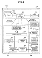
- Fig. 4 shows function blocks in various processing executed on the processor 21.
- interrupt processing 500, task processing 600, and scheduling processing 700 that are time-divided are executed in a multitasking operating system environment.
- the interrupt processing 500 is performed at interruption level and is not managed by the task scheduler 230.
- the task processing 600 is performed at task level and managed by the task scheduler 230.
- the scheduling processing 700 is performed at timer interruption level and is not managed by the task scheduler 230.
- Interrupt write-processing 310 and interrupt read-processing 320 from the host computer 50 of high priority are received as specific commands 330 and have priority.
- Interrupt write-processing 310 and interrupt read-processing of low priority are registered for a command queue 340 and performed as main I/O processing tasks 350 under the management of the task scheduler 230.
- the network interrupt processing 410 requested from the network server 60 is registered for a network queue 420 and executed as network processing tasks 430 under the management of the task scheduler 230.
- the interrupt processing operation time monitor 210 measures the time period (interrupt processing time) for which the processor resources are allocated to the interrupt processing 500.
- the task processing operation time monitor 22 measures the time period (task processing time) for which the processor resources are allocated to the task processing 600.
- the operation time manager 240 measures the interrupt processing time and task processing time at the point in time of interruption by timer processing 250. If either processing takes too much time, the balance of the ratio between the interrupt processing time and task processing time is adjusted based on the operation time allocation range table 800, normal state processing time allocation table 810, and restricted state operation time allocation table 820.
- the timer processing 250 is a process for updating the timer.
- interrupt processing operation time monitor 210 task processing operation time monitor 220, and operation time manager 240 are function modules realized in a multitasking operating system environment.
- Fig. 5 shows the operation time allocation range table 800.
- an operation time proportion (percentage) range for each kind of processing (main I/O task processing, main I/O interrupt processing, monitoring task processing, monitoring interrupt processing, network task processing, network interrupt processing, and OS processing) for a certain monitoring time period is set.
- the operation time proportion range for each kind of processing can be set to an optimum value according to the management form and network environment in the storage system 10.
- each operation time proportion range set in the operation time allocation range table 800 has a certain scope.
- the "-" mark in the table means no restrictation set for the operation time proportion.
- Fig. 6 shows the normal state operation time allocation table 810.
- a ceiling value for the operation time proportion for each kind of processing in the normal state is set.
- the ceiling value for the operation time proportion for each kind of processing in the normal state is set within the range set in the operation time allocation range table 800.
- the "normal state" indicates the state where the operation time is balanced between the interrupt processing 500 and task processing 600.
- Fig. 7 shows the restricted state operation time allocation table 820.
- a ceiling value for the operation time proportion for each kind of processing in each restricted state is set.
- the ceiling value for the operation time proportion for each kind of processing in each restricted state is set within the proportion range set in the operation time allocation range table 800.
- the "restricted state” means the state where the operation time is not balanced between the interrupt processing 500 and task processing 600, and the processing time is restricted. There may be a plurality of restricted states.
- Fig. 8 shows a time chart for each kind of processing in the process of shifting state from the normal state to the restricted state.
- a time period from a time T0 to a time T1 is set to "stage 1”
- a time period from a time T1 to a time T2 is set to "stage 2”
- a time period from a time T5 to a time T6 is set to "stage 6.”
- the time length in each stage is equivalent to that of the above described monitoring time period.
- the monitoring time consists of a plurality of units of time.
- the operation time manger 240 regularly checks the proportion of each interrupt processing and task processing in each of stages 1 to 6 at the times T0, T1, ... and T6 (the end of each stage).
- the operation time manager 240 restricts the proportion of that interrupt processing time or task processing time at the stage (N+1) based on the proportion set in the "restricted state M" in the restricted state operation time allocation table 820. Only one restricted state applies to the restricted state M based on a combination of processing, the operation time proportion of which exceeds the ceiling value at the end of stage N.
- the operation time proportions for the main I/O task processing and main I/O interrupt processing are 80 % and 20 % respectively. Because those operation time proportions are within the operation proportions set in the normal state operation time allocation table 810, the operation time manager 240 then adjusts the operation time proportion for each kind of processing at stage 2 based on the operation proportions set in the normal state operation time allocation table 810.
- the operation time proportions for the main I/O task processing and main I/O interrupt processing are 20 % and 80 % respectively. Because the operation time for the main I/O interrupt processing exceeds its 40% ceiling value, the operation time manager 240 adjusts the operation time proportion for each kind of processing at the stage 3 based on the "restricted state 8" set in the restricted state operation time allocation table 820.
- the operation time manager 240 restricts the operation time proportion for the main I/O interrupt processing to 40 %.
- the operation time proportion for the network interrupt processing time at stage 3 is 30 %, which exceeds the proportion (10 %) set in the normal state operation time allocation table 810. Accordingly, the operation time manager 240 adjusts the operation time proportion for each kind of processing at stage 4 based on the operation time proportions set for the "restricted state 9" in the restricted state operation time allocation table 820.
- the operation time manager 240 adjusts the operation time proportion for each kind of processing at stages 4, 5, and 6 in the same manner.
- Fig. 9 shows a time chart for each kind of processing in the process of shifting state from restricted state to normal state.
- a time period from time T7 to time T8 is set to "stage 8”
- a time period from time T8 to time T9 is set to "stage 9”
- a time period from time T12 to time T13 is set to "stage 13.”
- the time length in each of stages 8 to 13 is equivalent to the above described monitoring time period.
- the operation time manager 240 regularly checks the proportions for the interrupt processing time and task processing time during each stage at the times T7, T8, ... and T13 (at the end of each stage).
- the operation time manager 240 restricts the operation time proportion for the main I/O interrupt processing to 40 % and that for the network interrupt processing to 10 %. Because the operation time proportions for both the main I/O interrupt processing and network interrupt processing are at their ceiling values, the operation time manager 240 adjusts the operation time proportion for each kind of processing at stage 9 based on the operation time proportions set in the restricted state operation time allocation table 820.
- the operation time manager 240 adjusts the operation time proportion for each kind of processing at stage 10 based on the operation time proportion set for the "restricted state 1" in the restricted state operation time proportion table 820.
- the operation time manager 240 cancels the restricted state and adjusts the operation time proportion for each kind of processing at stage 11 based on the operation time proportions set in the normal state operation time allocation table 810.
- the operation time manager 240 adjusts the operation time proportion for each kind of processing at stages 11, 12, and 13 in the same manner.
- Fig. 11 is a flowchart illustrating interrupt processing time measurement processing.
- the interrupt processing time measurement processing is processing for calculating the total value of interrupt processing time at each stage, and is executed in an event-driven manner when an interrupt processing request to the storage system 10 is received. Sometimes the interrupt processing time measurement processing is performed several times during one stage.
- the interrupt processing operation time monitor 210 When receiving an interrupt request, the interrupt processing operation time monitor 210 starts the interrupt processing time measurement (step 1101).
- step 1104 If that interrupt request has been made for a specific command (step 1102; YES), the processor 21 promptly executes the specific command (step 1104).
- step 1102 If that interrupt request has not been made for a specific command (step 1102; NO), the processor 21 temporarily registers that interrupt request for the command queue 340 (step 1103).
- the interrupt processing operation monitor 210 ends the interrupt processing time measurement (step 1105), and adds the interrupt processing time measured in the steps 1101 to 1105 to the measurement result for the previous interrupt processing time measurement processing (step 1106).
- Fig. 12 is a flowchart illustrating task processing time measurement processing.
- the task processing time measurement processing is processing for calculating the total value of task processing time at each stage, and is performed in an event driven manner when the task processing is performed. Sometimes the task processing time measurement processing is performed several times during one stage.
- the task processing operation time monitor 220 starts the task processing time measurement (step 1201).
- the task processing operation time monitor 220 ends the task processing time measurement (step 1203) and adds the task processing time measured in the steps 1201 to 1203 to the measurement result for the previous task processing time measurement processing (step 1106).
- Fig. 13 is a flowchart illustrating scheduling processing.
- the scheduling processing is processing for adjusting the balance between the interrupt processing time and task processing time at each stage based on the above described normal state operation time allocation table 810 and restricted state operation time allocation table 820. Though details for the scheduling processing have been described referring to the time charts (Figs. 8 and 9), they are described here again with reference to the flowchart.
- the scheduling processing is performed when timer interruption of the timer processing 250 is received. Timer interruption occurs once per unit time. For example, if the monitoring time period consists of 100 time units, the timer interruption occurs 100 times per stage.
- Steps 1301 to 1306 described later are executed once per unit time (for example, those steps are executed 100 times per stage).
- a step 1307 described later is executed once per monitoring time period (i.e., at the end of each stage).
- the operation time manager unit 240 When receiving timer interruption (step 1301), the operation time manager unit 240 checks whether or not a monitoring time period has passed (i.e., whether or not it is at the end of each stage) (step 1302). If a monitoring time period has passed (step 1302; YES), the operation time manager 240 executes balance adjustment processing (step 1307). The balance adjustment processing will be described later in detail.
- the operation time manager 240 obtains the total value of the interrupt processing time in the monitoring time period from the interrupt processing operation time monitor 210 (step 1303), and obtains the total value of the task processing time in the monitoring time period from the task processing operation time monitor 220 (step 1304).
- the operation time manager 240 stops the task processing or masks the interrupt processing (step 1306). If neither the interrupt processing time nor task processing time reaches its ceiling value (step 1305; NO), the scheduling processing ends.
- Fig. 14 is a flowchart illustrating balance adjustment processing.
- Balance adjustment processing is a subroutine that is called and executed when a monitoring time period has passed (at the end of each stage).
- the operation time manager 240 calculates the proportions for the interrupt processing time and task processing time that occupy the monitoring time period (step 1401), and checks whether or not the proportion for the interrupt processing time or task processing time exceeds its ceiling value (step 1402).
- the operation time manager 240 sets the ceiling value of the proportion for the interrupt processing time or task processing time to the value set in the corresponding restricted state (step 1403).
- the operation time manager 240 clears the total interrupt processing time value and the total task processing time value in the monitoring time period to zero (step 1404).
- the interrupt processing 500 and task processing 600 requested of the storage system 10 internally and externally are scheduled in a balanced manner. Accordingly, even if high priority interrupt processing frequently occurs, the processor resources are not unequally allocated only to the interrupt processing. In other words, the processor resources are allocated to both the interrupt processing 500 and task processing 600 in a balanced manner according to the state of the burden on the storage system 10 and its usage.
Landscapes
- Engineering & Computer Science (AREA)
- Software Systems (AREA)
- Theoretical Computer Science (AREA)
- Physics & Mathematics (AREA)
- General Engineering & Computer Science (AREA)
- General Physics & Mathematics (AREA)
- Debugging And Monitoring (AREA)
Abstract
Description
- This application relates to and claims priority from
Japanese Patent Application No. 2006-56520, filed on March 2, 2006 - The present invention relates to a storage system and scheduling method that adjusts the balance between processing time for task processing, and interrupt processing requested internally or externally.
- In a database system such as a data center, that manages a large volume of data, data is managed by using a storage system such as a disk array system. A disk array system has a number of storage devices arranged in arrays, and provides storage resources in RAID (Redundant Arrays of Independent Inexpensive Disks) form to a host computer. The host computer and storage system are mutually connected via a device-sharing network such as a SAN (Storage Area Network).
- The network-connected storage system executes not only processing requested internally, including recovery processing for recovering any failure occurring in the disk drives, self-diagnosis processing for checking whether or not a failure is present in any disk drives, and backup processing for backing up data, but also processing requested externally, including access from a host computer and various network servers.
- Of the processing requested internally and externally, processing that needs a real-time response (readiness) has to be performed promptly, and efficient scheduling is necessary. For example,
Japanese Patent No. 2918297 - In network-connected storage systems, one that has only one processor and aims at low cost and high performance is being developed. In a storage system that processes both I/O requests from a host computer and access from various network servers in a multitasking operating system environment that operates on a single processor, when there are many high priority requests (hereinafter referred to as "specific commands"), most of the processor resources are assigned to those specific commands. As a result, barely any processor resources can be assigned to normal commands. The above problem occurs because, although a task scheduler schedules task processing, it does not schedule all processing including both interrupt processing and task processing. Improvement on that problem has been desired to prevent deterioration in the storage system performance.
- Accordingly, an object of the present invention is to solve the above problem by scheduling not only task processing, but all processing, including high priority processing, in a multitasking operating system environment that operates on a single processor.
- To preferably achieve the above object, a storage system according to an aspect of the present invention has a single processor that operates in a multitasking operating system environment. The storage system preferably includes an operation time manager that adjusts the balance of the ratio between interrupt processing time and task processing time to keep the processing time ratio between interrupt processing and task processing requested internally or externally within a predetermined range.
- When the proportion of interrupt processing time in a certain monitoring time period exceeds a predetermined range, the operation time manager preferably restricts interrupt processing in the subsequent monitoring time period. Meanwhile, when the proportion of interrupt processing time to certain monitoring time period is within a predetermined range, the restriction on interrupt processing may be cancelled in the subsequent monitoring time period. In other words, the operation time manager may restrict interrupt processing or cancel that restriction every monitoring time period according to the storage system workload.
- When the proportion of task processing time in a certain monitoring time period exceeds a predetermined range, the operation time manager may restrict task processing in the subsequent monitoring time period. Meanwhile, when the proportion of task processing time in a certain monitoring time period is within a predetermined range, the restriction to task processing may be cancelled in the subsequent monitoring time period. In other words, the operation time manager may restrict task processing or cancel that restrictation every monitoring time period according to the burden state in the storage system.
- According to aspects of the present invention, interrupt processing and task processing requested internally or externally can be scheduled in a balanced manner, and accordingly, storage system performance can be improved.
-
- Fig. 1 is a diagram showing the hardware configuration in the storage system according to an embodiment of the present invention.
- Fig. 2 is a diagram illustrating factors in interrupt processing and task processing requested by a storage system.
- Fig. 3 is a diagram illustrating the relationship between task processing and interrupt processing relating to control processing in the storage system.
- Fig. 4 is a block diagram showing various functions that operate on a processor.
- Fig. 5 is a diagram illustrating an operation time allocation range table.
- Fig. 6 is a diagram illustrating a normal state operation time allocation table.
- Fig. 7 is a diagram illustrating a restricted state operation time allocation table.
- Fig. 8 is a time chart for each kind of processing during the process of shifting state from the normal state to the restricted state.
- Fig. 9 is a time chart for each kind of processing during the process of shifting state from the restricted state to the normal state.
- Fig. 10 is a chart showing control processing priorities in the restricted states.
- Fig. 11 is a flowchart illustrating interrupt processing time measurement processing.
- Fig. 12 is a flowchart illustrating task processing time measurement processing.
- Fig. 13 is a flowchart illustrating the scheduling processing.
- Fig. 14 is a flowchart illustrating balance adjustment processing.
- An embodiment of the present invention will be described with reference to the drawings.
- Fig. 1 shows the main configuration of a
storage system 10 according to the present embodiment. Thestorage system 10 is connected, via acommunication network 40, to one ormore host computers 50 and one ormore network servers 60. - The
host computer 50 is a personal computer, workstation, or main frame. Application programs (e.g. web application software, streaming application software, e-business application software) are installed on thehost computer 50. - The
network server 60 is an SNMP (Simple Network Management Protocol) server for managing a network, an SNTP (Simple Network Time Protocol) server for managing a network time protocol, a backup server for managing backup and restoring, or a scan server for performing virus checks. - The
communication network server 40 may be a SAN (Storage Area Network), a LAN (Local Area Network), a WAN (Wide Area Network), the Internet, a dedicated line, or a public line. If thehost computer 50 is connected to thestorage system 10 via a SAN, thehost computer 50 requests data input/output in blocks, which are data management units in storage resources in thestorage system 10, according to Fibre Channel Protocol or iSCSI (Internet Small Computer System Interface) Protocol. If thehost computer 50 is connected to thestorage system 10 via a LAN, thehost computer 50 requests data input/output by file by designating a file name according to NFS (Network File System) or CIFS (Common Interface File System) protocol. To receive file access requests from thehost computer 50, thestorage system 10 has to have a NAS (Network Attached Storage) function. - The
storage system 10 is mainly made up with includes acontroller 20 andstorage device 30. - The
storage device 30 includes a plurality ofdisk drives 31. Thedisk drives 31 may be various disk drives, such as FC (Fibre Channel) disk drives, SATA (Serial Advanced Technology Attachment) disk drives, PATA (Parallel Advanced Technology Attachment) disk drives, FATA (Fibre Attached Technology Adapted) disk drives, and SCSI (Small Computer System Interface) disk drives. - The
controller 20 can control thestorage device 30 at a certain RAID level (e.g., 0, 1, or 5) defined in the RAID system. In a RAID group, one or more logical units, being access units for thehost computer 50, are defined. An LUN (Logical Unit Number) is allocated to each logical unit. - The
controller 20 is mainly made up with aprocessor 21,local memory 22,data controller 23,host interface 24,drive interface 25, andcache memory 26. Thecontroller 20 is a single processor having oneprocessor 21. - The
processor 21 controls I/O processing to/from thestorage device 30 in response to data input/output requests from thehost computer 50. Thelocal memory 20 stores a microprogram and various tables (operation time allocation range table 800, normal state operation time allocation table 810, and restricted stated operation time allocation table 820 described later) for theprocessor 21. Thecache memory 26 is buffer memory for temporarily storing write data that is to be written to thestorage device 30, or read data that has been read from thestorage device 30. Thecache memory 26 is non-volatile memory that prevents cache data to from being lost even when a power failure occurs in thestorage system 10. - The
data controller 23 mutually connects ahost interface 24,drive interface 25, andcache memory 26, and controls data transfer between thehost computer 50 andstorage device 30. More specifically, when write access is requested from thehost computer 50, thedata controller 23 writes write data received via thehost interface 24 from thehost computer 50, to thecache memory 26. Thedrive interface 25 writes the write data that has been written to thecache memory 26 to thestorage device 30. Meanwhile, when read access is requested from thehost computer 50, thedata controller 23 writes read data that has been read via thedrive interface 25 from thestorage device 30, to thecache memory 26, and also transfers the read data to thehost interface 24. If thestorage device 30 is managed at RAID level "5," thedata controller 23 calculates parity data. - The
host interface 24 is an interface controller for controlling the interfaces between thehost computer 50 andcontroller 20 and receives a block access request from thehost computer 50 according to Fibre Channel Protocol, or a file access request from thehost computer 50 according to a protocol of file transfer. Thedrive interface 25 controls the interface between thecontroller 20 andstorage device 30, and controls data input/output to/from thestorage device 30 according to a protocol that controls thestorage device 30. - Fig. 2 shows factors in interrupt
processing 500 and task processing 600 requested from thestorage system 10. Processing externally requested of thestorage system 10 includes main I/O task processing, main I/O interrupt processing, network task processing, and network interrupt processing. Processing internally requested of thestorage system 10 includes monitoring task processing, monitoring interrupt processing, failure task processing, failure interrupt processing, and OS processing. - More specific examples of processing for the
storage system 10 requested internally include self-diagnosis processing for checking whether or not a failure is present in the disk drives 31, backup processing for backing up data stored in adisk drive 31 to anotherdisk drive 31, and data recovery processing for recovering data by correcting errors using redundant data, operating the storage system in a degraded mode, and performing correction copy to aspare disk 33. - More specific examples of the processing for the
storage system 10 requested externally include an I/O request from thehost computer 50 and various processing requests from the network server 60 (e.g. SNMP processing, SNTP processing, backup request processing, and virus check processing). - Fig. 3 shows the relationship between task processing and interrupt processing relating to control processing for the
storage system 10. That relationship shows to which processing system (main I/O, monitoring, failure, and OS) each interrupt processing belongs, and to which processing system each task processing belongs. For example, the interruption name "Inter-CTL communication interruption" belongs to the main I/O interrupt processing. The task name "tDFCTL" belongs to the main I/O task processing. Because the details of the task processing and interrupt processing shown in Fig. 3 do not relate to the main feature of the present invention, their descriptions are omitted. - Fig. 4 shows function blocks in various processing executed on the
processor 21. On theprocessor 21, interrupt processing 500, task processing 600, andscheduling processing 700 that are time-divided are executed in a multitasking operating system environment. The interruptprocessing 500 is performed at interruption level and is not managed by thetask scheduler 230. Thetask processing 600 is performed at task level and managed by thetask scheduler 230. Thescheduling processing 700 is performed at timer interruption level and is not managed by thetask scheduler 230. - Interrupt write-
processing 310 and interrupt read-processing 320 from thehost computer 50 of high priority are received asspecific commands 330 and have priority. Interrupt write-processing 310 and interrupt read-processing of low priority are registered for acommand queue 340 and performed as main I/O processing tasks 350 under the management of thetask scheduler 230. - Meanwhile, the network interrupt
processing 410 requested from thenetwork server 60 is registered for anetwork queue 420 and executed asnetwork processing tasks 430 under the management of thetask scheduler 230. - The interrupt processing operation time monitor 210 measures the time period (interrupt processing time) for which the processor resources are allocated to the interrupt
processing 500. The task processing operation time monitor 22 measures the time period (task processing time) for which the processor resources are allocated to thetask processing 600. Theoperation time manager 240 measures the interrupt processing time and task processing time at the point in time of interruption bytimer processing 250. If either processing takes too much time, the balance of the ratio between the interrupt processing time and task processing time is adjusted based on the operation time allocation range table 800, normal state processing time allocation table 810, and restricted state operation time allocation table 820. Thetimer processing 250 is a process for updating the timer. - The above-described interrupt processing operation time monitor 210, task processing operation time monitor 220, and
operation time manager 240 are function modules realized in a multitasking operating system environment. - Next, processing for scheduling various processing (main I/O task processing, main I/O interrupt processing, monitoring task processing, monitoring interrupt processing, network task processing, network interrupt processing, OS processing) while adjusting the balance between the interrupt processing time and task processing time will be described in detail with reference to Figs. 5 to 14.
- Fig. 5 shows the operation time allocation range table 800. In the operation time allocation range table 800, an operation time proportion (percentage) range for each kind of processing (main I/O task processing, main I/O interrupt processing, monitoring task processing, monitoring interrupt processing, network task processing, network interrupt processing, and OS processing) for a certain monitoring time period is set. The operation time proportion range for each kind of processing can be set to an optimum value according to the management form and network environment in the
storage system 10. As shown in Fig. 5, each operation time proportion range set in the operation time allocation range table 800 has a certain scope. The "-" mark in the table means no restrictation set for the operation time proportion. - Fig. 6 shows the normal state operation time allocation table 810. In the normal state operation time allocation table 810, a ceiling value for the operation time proportion for each kind of processing in the normal state is set. The ceiling value for the operation time proportion for each kind of processing in the normal state is set within the range set in the operation time allocation range table 800. The "normal state" indicates the state where the operation time is balanced between the interrupt
processing 500 andtask processing 600. - Fig. 7 shows the restricted state operation time allocation table 820. In the restricted state operation time allocation table 820, a ceiling value for the operation time proportion for each kind of processing in each restricted state is set. The ceiling value for the operation time proportion for each kind of processing in each restricted state is set within the proportion range set in the operation time allocation range table 800. The "restricted state" means the state where the operation time is not balanced between the interrupt
processing 500 andtask processing 600, and the processing time is restricted. There may be a plurality of restricted states. - Fig. 8 shows a time chart for each kind of processing in the process of shifting state from the normal state to the restricted state. For ease of explanation, a time period from a time T0 to a time T1 is set to "
stage 1," a time period from a time T1 to a time T2 is set to "stage 2," ... and a time period from a time T5 to a time T6 is set to "stage 6." The time length in each stage is equivalent to that of the above described monitoring time period. The monitoring time consists of a plurality of units of time. Theoperation time manger 240 regularly checks the proportion of each interrupt processing and task processing in each ofstages 1 to 6 at the times T0, T1, ... and T6 (the end of each stage). - If the proportion of interrupt processing time or task processing time at stage N (N is an integer greater than 0) exceeds the proportion range set in the normal state operation time allocation table 810, the
operation time manager 240 restricts the proportion of that interrupt processing time or task processing time at the stage (N+1) based on the proportion set in the "restricted state M" in the restricted state operation time allocation table 820. Only one restricted state applies to the restricted state M based on a combination of processing, the operation time proportion of which exceeds the ceiling value at the end of stage N. - For example, at
stage 1 in the normal state, the operation time proportions for the main I/O task processing and main I/O interrupt processing are 80 % and 20 % respectively. Because those operation time proportions are within the operation proportions set in the normal state operation time allocation table 810, theoperation time manager 240 then adjusts the operation time proportion for each kind of processing atstage 2 based on the operation proportions set in the normal state operation time allocation table 810. - At
stage 2 in the normal state, the operation time proportions for the main I/O task processing and main I/O interrupt processing are 20 % and 80 % respectively. Because the operation time for the main I/O interrupt processing exceeds its 40% ceiling value, theoperation time manager 240 adjusts the operation time proportion for each kind of processing at thestage 3 based on the "restrictedstate 8" set in the restricted state operation time allocation table 820. - At
stage 3 in the restrictedstate 8, theoperation time manager 240 restricts the operation time proportion for the main I/O interrupt processing to 40 %. However, the operation time proportion for the network interrupt processing time atstage 3 is 30 %, which exceeds the proportion (10 %) set in the normal state operation time allocation table 810. Accordingly, theoperation time manager 240 adjusts the operation time proportion for each kind of processing atstage 4 based on the operation time proportions set for the "restrictedstate 9" in the restricted state operation time allocation table 820. - After that, the
operation time manager 240 adjusts the operation time proportion for each kind of processing atstages - Fig. 9 shows a time chart for each kind of processing in the process of shifting state from restricted state to normal state. For ease of explanation, a time period from time T7 to time T8 is set to "
stage 8," a time period from time T8 to time T9 is set to "stage 9," ..., and a time period from time T12 to time T13 is set to "stage 13." The time length in each ofstages 8 to 13 is equivalent to the above described monitoring time period. Theoperation time manager 240 regularly checks the proportions for the interrupt processing time and task processing time during each stage at the times T7, T8, ... and T13 (at the end of each stage). - At
stage 8 in the restrictedstate 9, theoperation time manager 240 restricts the operation time proportion for the main I/O interrupt processing to 40 % and that for the network interrupt processing to 10 %. Because the operation time proportions for both the main I/O interrupt processing and network interrupt processing are at their ceiling values, theoperation time manager 240 adjusts the operation time proportion for each kind of processing atstage 9 based on the operation time proportions set in the restricted state operation time allocation table 820. - At
stage 9 in the restrictedstate 9, the operation time proportion for the network interrupt processing is still at its 10 % ceiling value, but the operation time proportion for the main I/O interrupt processing is reduced to 30 %, which is lower than its 40 % ceiling value. Accordingly, theoperation time manager 240 adjusts the operation time proportion for each kind of processing atstage 10 based on the operation time proportion set for the "restrictedstate 1" in the restricted state operation time proportion table 820. - At
stage 10 in the restrictedstate 1, the operation time proportion for the network processing is reduced to 0 %, which is lower than its 10 % ceiling value, and the operation time proportion for the main I/O interrupt processing is reduced to 20 %, which is lower than its 40 % ceiling value. Accordingly, theoperation time manager 240 cancels the restricted state and adjusts the operation time proportion for each kind of processing atstage 11 based on the operation time proportions set in the normal state operation time allocation table 810. - After that, the
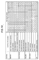
operation time manager 240 adjusts the operation time proportion for each kind of processing atstages - In the above described restricted states, not only is the operation time proportion for each kind of processing adjusted, but the control processing of high priority in main I/O, monitoring, failure, network, and OS processing may also take priority as shown in Fig. 10. In Fig. 10, the "o" mark indicates high priority, and the "x" mark indicates low priority.
- Fig. 11 is a flowchart illustrating interrupt processing time measurement processing. The interrupt processing time measurement processing is processing for calculating the total value of interrupt processing time at each stage, and is executed in an event-driven manner when an interrupt processing request to the
storage system 10 is received. Sometimes the interrupt processing time measurement processing is performed several times during one stage. - When receiving an interrupt request, the interrupt processing operation time monitor 210 starts the interrupt processing time measurement (step 1101).
- If that interrupt request has been made for a specific command (
step 1102; YES), theprocessor 21 promptly executes the specific command (step 1104). - If that interrupt request has not been made for a specific command (
step 1102; NO), theprocessor 21 temporarily registers that interrupt request for the command queue 340 (step 1103). - Next, the interrupt processing operation monitor 210 ends the interrupt processing time measurement (step 1105), and adds the interrupt processing time measured in the
steps 1101 to 1105 to the measurement result for the previous interrupt processing time measurement processing (step 1106). - Fig. 12 is a flowchart illustrating task processing time measurement processing. The task processing time measurement processing is processing for calculating the total value of task processing time at each stage, and is performed in an event driven manner when the task processing is performed. Sometimes the task processing time measurement processing is performed several times during one stage.
- When task processing is called by the
task scheduler 230, the task processing operation time monitor 220 starts the task processing time measurement (step 1201). - After the task processing is executed by the processor 21 (step 1202), the task processing operation time monitor 220 ends the task processing time measurement (step 1203) and adds the task processing time measured in the
steps 1201 to 1203 to the measurement result for the previous task processing time measurement processing (step 1106). - Fig. 13 is a flowchart illustrating scheduling processing. The scheduling processing is processing for adjusting the balance between the interrupt processing time and task processing time at each stage based on the above described normal state operation time allocation table 810 and restricted state operation time allocation table 820. Though details for the scheduling processing have been described referring to the time charts (Figs. 8 and 9), they are described here again with reference to the flowchart. The scheduling processing is performed when timer interruption of the
timer processing 250 is received. Timer interruption occurs once per unit time. For example, if the monitoring time period consists of 100 time units, the timer interruption occurs 100 times per stage. -
Steps 1301 to 1306 described later are executed once per unit time (for example, those steps are executed 100 times per stage). Astep 1307 described later is executed once per monitoring time period (i.e., at the end of each stage). - When receiving timer interruption (step 1301), the operation
time manager unit 240 checks whether or not a monitoring time period has passed (i.e., whether or not it is at the end of each stage) (step 1302). If a monitoring time period has passed (step 1302; YES), theoperation time manager 240 executes balance adjustment processing (step 1307). The balance adjustment processing will be described later in detail. - If a monitoring time period has not passed (
step 1302; NO), theoperation time manager 240 obtains the total value of the interrupt processing time in the monitoring time period from the interrupt processing operation time monitor 210 (step 1303), and obtains the total value of the task processing time in the monitoring time period from the task processing operation time monitor 220 (step 1304). - When the interrupt processing time or task processing time reaches its ceiling value (the ceiling value set in the restricted state operation time allocation table 820) (
step 1305; YES), theoperation time manager 240 stops the task processing or masks the interrupt processing (step 1306). If neither the interrupt processing time nor task processing time reaches its ceiling value (step 1305; NO), the scheduling processing ends. - Fig. 14 is a flowchart illustrating balance adjustment processing. Balance adjustment processing is a subroutine that is called and executed when a monitoring time period has passed (at the end of each stage).
- The
operation time manager 240 calculates the proportions for the interrupt processing time and task processing time that occupy the monitoring time period (step 1401), and checks whether or not the proportion for the interrupt processing time or task processing time exceeds its ceiling value (step 1402). - If the proportion for the interrupt processing time or the task processing time exceeds its ceiling value (
step 1402; YES), theoperation time manager 240 sets the ceiling value of the proportion for the interrupt processing time or task processing time to the value set in the corresponding restricted state (step 1403). - If neither the proportion for the interrupt processing time nor the task processing time exceeds its ceiling value (
step 1402; NO), or after the balance adjustment processing (step 1403) is executed, theoperation time manager 240 clears the total interrupt processing time value and the total task processing time value in the monitoring time period to zero (step 1404). - According to the present embodiment, the interrupt
processing 500 and task processing 600 requested of thestorage system 10 internally and externally are scheduled in a balanced manner. Accordingly, even if high priority interrupt processing frequently occurs, the processor resources are not unequally allocated only to the interrupt processing. In other words, the processor resources are allocated to both the interruptprocessing 500 and task processing 600 in a balanced manner according to the state of the burden on thestorage system 10 and its usage.
Claims (9)
- A storage system (10) having a single processor (21) that operates in a multitasking operation system environment, the storage system (10) comprising:an operation time manager(240) for adjusting the balance between processing time proportions for interrupt processing (500) and task processing (600)that are requested of the storage system both internally and externally so that those processing time proportions become within respective predetermined ranges.
- The storage system (10) according to claim 1, wherein when the processing time proportion for the interrupt processing (500) in a certain monitoring time period is not within the predetermined range, the operation time manager (240) restricts the interrupt processing (500) in the subsequent monitoring time period; and when the processing time proportion for the interrupt processing time in a certain monitoring time period is within the predetermined range, the operation time manager (240) cancels any interrupt processing restriction in the subsequent monitoring time period.
- The storage system (10) according to claim 1 or claim 2, wherein when the task processing time proportion in a certain monitoring time period is not within the predetermined range, the operation time manager (240) restricts the task processing (600) in the subsequent monitoring time period; and when the task processing proportion in monitoring time period is within the predetermined range, the operation time manager (240) cancels any task processing restriction in the subsequent monitoring time period.
- The storage system (10) according to any one of claims 1 to 3, wherein the interrupt processing (500) and task processing (600) requested of the storage system (10) externally include a processing request relating to main I/O or a network.
- The storage system (10) according to any one of claims 1 to 4, wherein the interrupt processing (500) and task processing (600) requested of the storage system (10) internally and externally includes a request for processing relating to monitoring or failure.
- A storage system (10) having a single processor (21) that operates a multitasking operation system, the storage system (10) comprising:an interrupt processing operation time monitor (210) for regularly measuring interrupt processing time every fixed monitoring time period;a task processing operation time monitor (220) for regularly measuring task processing time every fixed monitoring time period; andan operation time manager (240) for adjusting the balance between processing time proportions for interrupt processing (500) and task processing (600) requested of the storage system (10) internally and externally so that those processing time proportions become within respective predetermined ranges,wherein when the interrupt processing time proportion in a certain monitoring time period is not within the predetermined range, the operation time manager (240) restricts the interrupt processing in the subsequent monitoring time period, and when the interrupt processing time is within the predetermined range in a certain monitoring time period, the operation time manager (240) cancels any interrupt processing restriction in the subsequent monitoring time period; and when the task processing time proportion in a certain monitoring time period is not within the predetermined range, the operation time manager (240) restricts the task processing in the subsequent monitoring time period, and when the task processing time proportion is within the predetermined range, the operation time manager (240) cancels any task processing restriction in the subsequent monitoring time period.
- A method for scheduling interrupt processing (500) and task processing (600) requested, internally and externally, of a storage system (10) in a multitasking operating system environment that operates on a single processor (21), the method comprising the steps of:regularly measuring interrupt processing time every fixed monitoring time period;regularly measuring task processing time every fixed monitoring time period; andadjusting the balance between the processing time proportions for interrupt processing (500) and task processing (600) requested of the storage system (10) both internally and externally so that those processing time proportions become within respective predetermined ranges.
- The scheduling method according to claim 7, the balance adjusting step (1307) further including the step of, when the interrupt processing time proportion in a certain monitoring time period is not within the predetermined range, restricting interrupt processing in the subsequent monitoring time period; and when the interrupt processing time proportion in a certain monitoring time period is within the predetermined range, canceling any interrupt processing restriction in the subsequent monitoring time period.
- The scheduling method according to claim 7 or claim 8, the balance adjusting step (1307) further including the step of, when the task processing time proportion in a certain monitoring time period is not within the predetermined range, restricting task processing in the subsequent monitoring time period; and when the task processing time proportion in a certain monitoring time period is within the predetermined range, canceling any task processing restriction in the subsequent monitoring time period.
Applications Claiming Priority (1)
| Application Number | Priority Date | Filing Date | Title |
|---|---|---|---|
| JP2006056520A JP4856983B2 (en) | 2006-03-02 | 2006-03-02 | Storage system and scheduling method |
Publications (2)
| Publication Number | Publication Date |
|---|---|
| EP1830258A2 true EP1830258A2 (en) | 2007-09-05 |
| EP1830258A3 EP1830258A3 (en) | 2008-12-17 |
Family
ID=38282867
Family Applications (1)
| Application Number | Title | Priority Date | Filing Date |
|---|---|---|---|
| EP06254474A Withdrawn EP1830258A3 (en) | 2006-03-02 | 2006-08-29 | Storage system and scheduling method |
Country Status (3)
| Country | Link |
|---|---|
| US (1) | US7950013B2 (en) |
| EP (1) | EP1830258A3 (en) |
| JP (1) | JP4856983B2 (en) |
Cited By (1)
| Publication number | Priority date | Publication date | Assignee | Title |
|---|---|---|---|---|
| EP2495656A1 (en) * | 2011-03-02 | 2012-09-05 | Research In Motion Limited | Enhanced prioritising and unifying interrupt controller |
Families Citing this family (13)
| Publication number | Priority date | Publication date | Assignee | Title |
|---|---|---|---|---|
| US8099637B2 (en) * | 2007-10-30 | 2012-01-17 | Hewlett-Packard Development Company, L.P. | Software fault detection using progress tracker |
| JP5256925B2 (en) * | 2008-08-12 | 2013-08-07 | 富士通モバイルコミュニケーションズ株式会社 | Mobile terminal device |
| US8239873B2 (en) * | 2008-08-12 | 2012-08-07 | Verizon Patent And Licensing Inc. | Speedy event processing |
| JP5308383B2 (en) * | 2010-03-18 | 2013-10-09 | パナソニック株式会社 | Virtual multiprocessor system |
| JP5804075B2 (en) * | 2011-11-11 | 2015-11-04 | 富士通株式会社 | Electronic computer and interrupt control method |
| WO2015020636A1 (en) * | 2013-08-06 | 2015-02-12 | Hitachi, Ltd. | Method and apparatus of storage system which stores information for relationship between logical volumes and operations |
| JP6241144B2 (en) * | 2013-08-30 | 2017-12-06 | 富士通株式会社 | Control program, control method, and control apparatus |
| US10523585B2 (en) | 2014-12-19 | 2019-12-31 | Amazon Technologies, Inc. | System on a chip comprising multiple compute sub-systems |
| US10394731B2 (en) | 2014-12-19 | 2019-08-27 | Amazon Technologies, Inc. | System on a chip comprising reconfigurable resources for multiple compute sub-systems |
| US11200192B2 (en) | 2015-02-13 | 2021-12-14 | Amazon Technologies. lac. | Multi-mode system on a chip |
| US9588921B2 (en) * | 2015-02-17 | 2017-03-07 | Amazon Technologies, Inc. | System on a chip comprising an I/O steering engine |
| WO2016194171A1 (en) * | 2015-06-03 | 2016-12-08 | 株式会社日立製作所 | Storage system |
| US20200233702A1 (en) * | 2017-03-21 | 2020-07-23 | Mitsubishi Electric Corporation | Control apparatus and computer readable medium |
Family Cites Families (22)
| Publication number | Priority date | Publication date | Assignee | Title |
|---|---|---|---|---|
| JP2918297B2 (en) | 1990-06-18 | 1999-07-12 | 富士通株式会社 | Interrupt control method |
| US5542076A (en) * | 1991-06-14 | 1996-07-30 | Digital Equipment Corporation | Method and apparatus for adaptive interrupt servicing in data processing system |
| JP3480973B2 (en) * | 1993-11-30 | 2003-12-22 | 富士通株式会社 | Behavior analysis device for parallel processing system |
| JPH09185516A (en) * | 1995-12-28 | 1997-07-15 | Hitachi Ltd | Multitask priority control method |
| IL116708A (en) * | 1996-01-08 | 2000-12-06 | Smart Link Ltd | Real-time task manager for a personal computer |
| JP3037182B2 (en) * | 1997-02-17 | 2000-04-24 | 日本電気株式会社 | Task management method |
| JPH1165623A (en) * | 1997-08-20 | 1999-03-09 | Denso Corp | Programmable controller |
| JP3189810B2 (en) * | 1998-11-19 | 2001-07-16 | 日本電気株式会社 | QoS controller |
| US6467008B1 (en) * | 1999-03-01 | 2002-10-15 | Sun Microsystems, Inc. | Method and apparatus for indicating an interrupt in a network interface |
| US6633942B1 (en) * | 1999-08-12 | 2003-10-14 | Rockwell Automation Technologies, Inc. | Distributed real-time operating system providing integrated interrupt management |
| US6754690B2 (en) * | 1999-09-16 | 2004-06-22 | Honeywell, Inc. | Method for time partitioned application scheduling in a computer operating system |
| JP2001337841A (en) * | 2000-05-26 | 2001-12-07 | Nec Eng Ltd | Task control unit |
| JP4318914B2 (en) * | 2002-12-26 | 2009-08-26 | 富士通株式会社 | Storage system and dynamic load management method thereof |
| TW200502847A (en) * | 2003-07-08 | 2005-01-16 | Benq Corp | Control device and method for reducing number of interrupts in a processor |
| EP1653354A4 (en) * | 2003-08-04 | 2008-03-26 | Hitachi Ltd | REAL-TIME CONTROL SYSTEM |
| US7353285B2 (en) | 2003-11-20 | 2008-04-01 | International Business Machines Corporation | Apparatus, system, and method for maintaining task prioritization and load balancing |
| US7120717B2 (en) * | 2004-02-13 | 2006-10-10 | Hewlett-Packard Development Company, L.P. | Method and apparatus for controlling interrupt storms |
| US7444450B2 (en) * | 2004-04-28 | 2008-10-28 | Hewlett-Packard Development Company, L.P. | Method and system for detecting excessive interrupt processing for a processor |
| US7275122B2 (en) * | 2004-04-28 | 2007-09-25 | Hewlett-Packard Development Company, L.P. | Method and system for maintaining a desired service level for a processor receiving excessive interrupts |
| US20050246461A1 (en) * | 2004-04-29 | 2005-11-03 | International Business Machines Corporation | Scheduling threads in a multi-processor computer |
| US7634589B2 (en) * | 2004-09-23 | 2009-12-15 | International Business Machines Corporation | Method for controlling peripheral adapter interrupt frequency by estimating processor load in the peripheral adapter |
| US7581052B1 (en) * | 2005-08-22 | 2009-08-25 | Sun Microsystems, Inc. | Approach for distributing multiple interrupts among multiple processors |
-
2006
- 2006-03-02 JP JP2006056520A patent/JP4856983B2/en not_active Expired - Fee Related
- 2006-04-21 US US11/407,972 patent/US7950013B2/en not_active Expired - Fee Related
- 2006-08-29 EP EP06254474A patent/EP1830258A3/en not_active Withdrawn
Cited By (1)
| Publication number | Priority date | Publication date | Assignee | Title |
|---|---|---|---|---|
| EP2495656A1 (en) * | 2011-03-02 | 2012-09-05 | Research In Motion Limited | Enhanced prioritising and unifying interrupt controller |
Also Published As
| Publication number | Publication date |
|---|---|
| EP1830258A3 (en) | 2008-12-17 |
| US7950013B2 (en) | 2011-05-24 |
| JP4856983B2 (en) | 2012-01-18 |
| JP2007233847A (en) | 2007-09-13 |
| US20070209037A1 (en) | 2007-09-06 |
Similar Documents
| Publication | Publication Date | Title |
|---|---|---|
| US8365023B2 (en) | Runtime dynamic performance skew elimination | |
| US8584128B1 (en) | Techniques for adjusting priorities associated with servicing requests | |
| US8214580B2 (en) | Solid state drive with adjustable drive life and capacity | |
| US6912635B2 (en) | Distributing workload evenly across storage media in a storage array | |
| US7950013B2 (en) | System for monitoring time proportion for interrupt or task processing with restriction placed in subsequent monitoring time period when allowable time proportion is exceed | |
| US7814351B2 (en) | Power management in a storage array | |
| US7954021B2 (en) | Solid state drive with flash sparing | |
| US7454583B2 (en) | Storage controller and control method for dynamically accomodating increases and decreases in difference data | |
| US8250257B1 (en) | Techniques for balancing system I/O load | |
| US8806070B2 (en) | Storage device, and storage device control method | |
| US9547528B1 (en) | Pizza scheduler | |
| CN1916833A (en) | Method and system for storaging network dynamic | |
| US12118409B2 (en) | Methods for dynamic throttling to satisfy minimum throughput service level objectives and devices thereof | |
| CN110737390A (en) | Method, apparatus and computer program product for managing a storage system | |
| US9298493B1 (en) | Managing system I/O load | |
| US7434012B1 (en) | Techniques for media scrubbing | |
| US8843714B1 (en) | Write pacing simulation tool | |
| US20240004563A1 (en) | Performance Efficient and Resilient Creation of Network Attached Storage Obects | |
| US7178146B1 (en) | Pizza scheduler | |
| EP1758016A1 (en) | Storage system and storage control method without requiring formatting of storage device | |
| US20140068214A1 (en) | Information processing apparatus and copy control method | |
| US11586516B2 (en) | Storage system, storage device, and storage device management method | |
| US9483371B2 (en) | Storage system, control apparatus, computer product, and control method | |
| CN111427512A (en) | A flow control method and device | |
| JP2001312372A (en) | Disk controller |
Legal Events
| Date | Code | Title | Description |
|---|---|---|---|
| PUAI | Public reference made under article 153(3) epc to a published international application that has entered the european phase |
Free format text: ORIGINAL CODE: 0009012 |
|
| 17P | Request for examination filed |
Effective date: 20060918 |
|
| AK | Designated contracting states |
Kind code of ref document: A2 Designated state(s): AT BE BG CH CY CZ DE DK EE ES FI FR GB GR HU IE IS IT LI LT LU LV MC NL PL PT RO SE SI SK TR |
|
| AX | Request for extension of the european patent |
Extension state: AL BA HR MK YU |
|
| PUAL | Search report despatched |
Free format text: ORIGINAL CODE: 0009013 |
|
| AK | Designated contracting states |
Kind code of ref document: A3 Designated state(s): AT BE BG CH CY CZ DE DK EE ES FI FR GB GR HU IE IS IT LI LT LU LV MC NL PL PT RO SE SI SK TR |
|
| AX | Request for extension of the european patent |
Extension state: AL BA HR MK RS |
|
| AKX | Designation fees paid |
Designated state(s): DE FR GB IE |
|
| STAA | Information on the status of an ep patent application or granted ep patent |
Free format text: STATUS: THE APPLICATION IS DEEMED TO BE WITHDRAWN |
|
| 18D | Application deemed to be withdrawn |
Effective date: 20090618 |