EP1830212A2 - Zoom lens and image pickup apparatus - Google Patents
Zoom lens and image pickup apparatus Download PDFInfo
- Publication number
- EP1830212A2 EP1830212A2 EP07103204A EP07103204A EP1830212A2 EP 1830212 A2 EP1830212 A2 EP 1830212A2 EP 07103204 A EP07103204 A EP 07103204A EP 07103204 A EP07103204 A EP 07103204A EP 1830212 A2 EP1830212 A2 EP 1830212A2
- Authority
- EP
- European Patent Office
- Prior art keywords
- lens group
- lens
- sub
- positive
- zoom
- Prior art date
- Legal status (The legal status is an assumption and is not a legal conclusion. Google has not performed a legal analysis and makes no representation as to the accuracy of the status listed.)
- Withdrawn
Links
Images







Classifications
-
- G—PHYSICS
- G02—OPTICS
- G02B—OPTICAL ELEMENTS, SYSTEMS OR APPARATUS
- G02B27/00—Optical systems or apparatus not provided for by any of the groups G02B1/00 - G02B26/00, G02B30/00
- G02B27/64—Imaging systems using optical elements for stabilisation of the lateral and angular position of the image
- G02B27/646—Imaging systems using optical elements for stabilisation of the lateral and angular position of the image compensating for small deviations, e.g. due to vibration or shake
-
- G—PHYSICS
- G02—OPTICS
- G02B—OPTICAL ELEMENTS, SYSTEMS OR APPARATUS
- G02B15/00—Optical objectives with means for varying the magnification
- G02B15/14—Optical objectives with means for varying the magnification by axial movement of one or more lenses or groups of lenses relative to the image plane for continuously varying the equivalent focal length of the objective
- G02B15/143—Optical objectives with means for varying the magnification by axial movement of one or more lenses or groups of lenses relative to the image plane for continuously varying the equivalent focal length of the objective having three groups only
- G02B15/1435—Optical objectives with means for varying the magnification by axial movement of one or more lenses or groups of lenses relative to the image plane for continuously varying the equivalent focal length of the objective having three groups only the first group being negative
- G02B15/143507—Optical objectives with means for varying the magnification by axial movement of one or more lenses or groups of lenses relative to the image plane for continuously varying the equivalent focal length of the objective having three groups only the first group being negative arranged -++
Definitions
- zoom lenses having such an image stabilization function for correcting the image blur caused by the vibration at the shooting.
- Japanese Unexamined Patent Application Publication No. 2003-582569 suggests a zoom lens including a first lens group having a negative refractive power, a second lens group having a positive refractive power, and a third lens group having a positive refractive power, and stabilizing an image by moving the second lens group in a direction orthogonal to the optical axis of the zoom lens.
- a zoom lens including a first lens group having a negative refractive power, and a second lens group having a positive refractive power, the second lens group being divided into a positive front group and a positive rear group, and stabilizing an image by moving the front or rear group in the direction orthogonal to the optical axis.
- the zoom lens disclosed in the aforementioned publication is entirely shifted (moved) in the direction orthogonal to the optical axis as an image stabilization group. Owing to this, a driving system for driving the second lens group by a distance for correcting the camera shake is requested to be controlled highly accurately especially at a telescope end state, thereby increasing the cost.
- the number of lenses of the image stabilization lens group is large and the weight thereof is also large, thereby increasing the load to be applied to a deflection driving system that shifts the image stabilization lens group.
- the zoom lens capable of stabilizing an image by way of the known three-lens groups only achieves a zoom ratio of approximately 2. This may not meet the demands of users who want a zoom ratio of 3 or higher.
- a zoom lens according to an embodiment of the present invention includes a first lens group having a negative refractive power, a second lens group having a positive refractive power, and a third lens group having a positive refractive power, the lens groups being sequentially aligned from an object side, and the zoom lens has the following configurations.
- the first lens group is moved along an optical axis of the zoom lens
- the second lens group is moved along the optical axis toward the object side, during zooming from a wide-angle end state to a telephoto end state.
- the third lens group includes a negative sub-lens group having a negative refractive power, and a positive sub-lens group having a positive refractive power, the sub-lens groups being sequentially aligned from the object side.
- An image may be shifted by moving the positive sub-lens group in a direction orthogonal to the optical axis.
- conditional expression (1) is satisfied, (1) 0.3 ⁇ 1 - ⁇ ⁇ 2.5, where ⁇ is a magnification of the positive sub-lens group of the third lens group at the telephoto end state.
- a zoom lens according to an embodiment of the present invention includes a first lens group having a negative refractive power, a second lens group having a positive refractive power, and a third lens group having a positive refractive power, the lens groups being sequentially aligned from an object side.
- the first lens group is moved along an optical axis of the zoom lens
- the second lens group is moved along the optical axis toward the object side, during zooming from a wide-angle end state to a telephoto end state.
- the third lens group includes a negative sub-lens group having a negative refractive power, and a positive sub-lens group having a positive refractive power, the sub-lens groups being sequentially aligned from the object side.
- An image may be shifted by moving the positive sub-lens group in a direction orthogonal to the optical axis. Also, the following conditional expression (1) is satisfied, 0.3 ⁇ 1 - ⁇ ⁇ 2.5 , where ⁇ is a magnification of the positive sub-lens group of the third lens group at the telephoto end state.
- the final third lens group is divided into the positive sub-lens group and the negative sub-lens group, and the positive sub-lens group serves as an image stabilization lens group that is shifted in the direction orthogonal to the optical axis.
- an image stabilization driving system for shifting the image stabilization lens group may be disposed at a position closest to the image side, the area being relatively vacant. Accordingly, the interference between the image stabilization driving system and other driving systems, such as a shutter and iris unit driving system and a zoom driving system, may be minimized.
- zooming may be performed by using a first lens group, and the negative and positive sub-lens groups of the third lens group.
- the use of the negative sub-lens group for zooming may eliminate the interference between the zoom driving system and the image stabilization driving system, thereby promoting miniaturization of the zoom lens.
- the above-mentioned conditional expression (1) defines a proportion of a shift amount of an image in the direction orthogonal to the optical axis relative to a moving distance of the image stabilization lens group in the direction orthogonal to the optical axis.
- a value is below the lower limit of the conditional expression (1), the moving distance of the image stabilization lens group necessary for shifting the image by a predetermined amount is increased.
- the driving system for shifting the image stabilization lens group becomes large, thereby resulting in an increase in size.
- a value is above the upper limit of the conditional expression (1), since the shift amount of the image relative to the moving distance of the image stabilization lens group is increased as described above, the moving distance of the image stabilization lens group is necessary to be highly accurately controlled. Due to this, parts tolerance and assembly precision, as well as accurate control of a detecting system and a driving system are necessary, thereby being extremely high cost.
- the image stabilization may be performed by entirely shifting the second lens group in the direction orthogonal to the optical axis.
- the value may be above the upper limit of the conditional expression (1) especially at the telescope end state to attain a zoom ratio of 3 or higher.
- the image stabilization is performed by moving (shifting) the positive sub-lens group of the third lens group in the direction orthogonal to the optical axis. Since the variation in magnification of the positive sub-lens group is small, the zoom ratio may be 3 or higher without the value being above the upper limit of the conditional expression (1).
- the negative sub-lens group of the third lens group may satisfy the following conditional expression (2), 1.0 ⁇ Rn / fw ⁇ 1.5 , where Rn is a curvature radius of a lens surface closest to the image side of the negative sub-lens group of the third lens group, and fw is a focal length of the whole lens system at the wide-angle end state.
- the conditional expression (2) defines a surface profile closest to the image side of the negative sub-lens group of the third lens group.
- a value is below the lower limit of the conditional expression (2), i.e., when a curvature radius of a surface closest to the image side of the negative sub-lens group is decreased and an effect for diverging light beam emitted from the negative sub-lens group becomes small
- the distance between the negative sub-lens group and the positive sub-lens group is necessary to be increased for providing effective telecentricity at the positive sub-lens group, and hence, it may be difficult to miniaturize the whole optical system.
- the positive sub-lens group of the third lens group may satisfy the following conditional expression (3), - 1.0 ⁇ CF + CR / CF - CR ⁇ 0 , where CF is a curvature radius of a lens surface closest to the object side of the positive sub-lens group of the third lens group, and CR is a curvature radius of a lens surface closest to the image side of the positive sub-lens group of the third lens group.
- the conditional expression (3) defines a profile of the image stabilization lens group.
- a value is below the lower limit of the conditional expression (3), i.e., when CF is relatively small, it may be difficult to correct distortion and variation in image plane occurring in the image stabilization.
- the value is above the upper limit of the conditional expression (3), i.e., CF is relatively large, it may be difficult to miniaturize the optical system.
- x y 2 ⁇ c 2 1 + 1 - 1 + K ⁇ y 2 ⁇ c 2 1 / 2 + ⁇ ⁇ A ⁇ i ⁇ y i
- x is a distance along the optical axis from a lens vertex
- y is a height in a direction orthogonal to the optical axis
- c is a paraxial curvature at the lens vertex
- K is a conic constant
- Ai is an aspherical coefficient at an i-th order.
- FIG. 1 is an illustration showing a lens arrangement of a zoom lens 1 according to a first embodiment.
- a first lens group G1 includes a negative meniscus lens L1 having an aspherical surface at the image side and a convex surface at the object side, and a cemented lens of a negative meniscus lens L2 having a convex surface at the object side and a positive meniscus lens L3 having a concave surface at the image side, the lenses being sequentially aligned from the object side.
- a second lens group G2 includes a cemented lens of a biconvex lens L4 and a negative meniscus lens L5 having a convex surface at the image side, and a positive meniscus lens L6 having an aspherical surface at the image side and a convex surface at the object side, the lenses being sequentially aligned from the object side.
- a third lens group G3 includes a negative meniscus lens L7 having a convex surface at the object side, and a biconvex lens L8 having an aspherical surface at the object side, the lenses being sequentially aligned from the object side.
- the negative meniscus lens L7 defines a negative sub-lens group G3n
- the biconvex lens L8 defines a positive sub-lens group G3p.
- the positive sub-lens group G3p is shifted in a direction orthogonal to an optical axis x of the zoom lens 1, an image may be shifted.
- Table 1 shows specific values of a first numerical example in which specific numerical values are applied to the first embodiment.
- Surface No. represents an i-th surface counted from the object side
- R represents a paraxial curvature radius of the i-th surface
- D represents an on-axis surface distance between the i-th surface and an i+ 1-th surface
- ⁇ d represents an Abbe number of the surface relative to the d-line.
- R represents that the surface is a flat surface
- ASP represents that the surface is an aspherical surface.
- a surface distance D5 between the first lens group G1 and the second lens group G2, a surface distance D11 between the second lens group G2 and the third lens group G3, and a surface distance D15 between the third lens group G3 and the filters FL, are varied, during zooming from the wide-angle end state to the telephoto end state.
- Table 2 Fno. 2.84 3.11 4.03 f 5. 50 7.72 15.40 ⁇ 33.43 25.09 13.12 D5 22.771 13.469 1.941 D11 1.914 2.163 3.348 D15 2.940 5.066 11.624
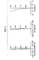
- Figs. 2, 3 and 4 show aberration diagrams at infinity according to the first numerical example.
- Table 4 shows specific values of a second numerical example in which specific numerical values are applied to the second embodiment.
- Table 4 Surface No. R D Nd ⁇ d 1 117.681 1.200 1.74330 49.2 2 6.852 ASP 3.885 3 14.860 1.227 1.92286 20.9 4 21.928 D4 5 16.611 2.185 1.71300 53.9 6 -15.213 0.450 1.83400 37.3 7 -42.322 1.000 8 INF 1.544 9 6.642 ASP 1.354 1.58913 61.3 10 24.423 D10 11 13.974 0.508 1.84666 23.8 12 5.032 6.268 13 10.513 ASP 2.253 1.51680 64.2 14 -38.596 D14 15 INF 2.300 1.51680 64.2 16 INF 0.700 17 INF 0.500 1.51680 64.2 18 INF 1.000 19 INF
- a 2nd surface, a 9th surface, and a 13th surface each have an aspherical surface.
- Table 6 shows aspherical coefficients A4, A6, A8 and A10 at a 4th order, a 6th order, an 8th order and a 10th order of each surface, together with conic constants K.
- Figs. 6, 7 and 8 show aberration diagrams at infinity according to the second numerical example.
- the spherical aberration curves are plotted by a solid line for the d-line, a broken line for the C-line, and a dotted-chain line for the g-line.
- the astigmatism curves are plotted by a solid line for a sagittal image surface, and a broken line for a meridional image surface.
- a second lens group G2 includes a cemented lens of a biconvex lens L4 and a negative meniscus lens L5 having a convex surface at the image side, and a positive meniscus lens L6 having an aspherical surface at the image side and a convex surface at the object side, the lenses being sequentially aligned from the object side.
- a third lens group G3 includes a negative meniscus lens L7 having a convex surface at the object side, and a biconvex lens L8 having an aspherical surface at the object side, the lenses being sequentially aligned from the object side.
- the negative meniscus lens L7 defines a negative sub-lens group G3n
- the biconvex lens L8 defines a positive sub-lens group G3p.
- the positive sub-lens group G3p is shifted in a direction orthogonal to an optical axis x of the zoom lens 3, an image may be shifted.
- An aperture stop S is disposed between the negative meniscus lens L4 and the positive meniscus lens L5 of the second lens group G2.
- Filters FL such as a low pass filter and an infrared cut filter, are disposed between the third lens group G3 and an image plane IMG.
- An aperture stop S is disposed between the biconcave lens L5 and the biconvex L6 of the second lens group G2.
- Filters FL such as a low pass filter and an infrared cut filter, are disposed between the third lens group G3 and an image plane IMG.
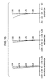
- Figs. 14, 15 and 16 show aberration diagrams at infinity according to the fourth numerical example.
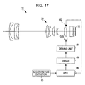
- Fig. 17 shows an image pickup apparatus according to an embodiment of the present invention.
- An image pickup apparatus 10 includes a zoom lens 20, an image pickup device 30 that converts an optical image produced by the zoom lens 20 into an electric signal, a camera shake detector 50 that detects shake of the main body of the image pickup device 30, and an image stabilization controller that controls variation in position of an object image to be produced, by driving a driver to move the image stabilization lens group (G3p) of the zoom lens 20 in the direction orthogonal to the optical axis of the zoom lens 20 in accordance with the shake of the main body of the image pickup device 30 detected by the camera shake detector 50.
- the image pickup device 30 may employ a photoelectric converter, such as a CCD (Charge Coupled Device) or CMOS (Complementary Metal-Oxide Semiconductor).
- the zoom lens 20 may employ the zoom lens according to the embodiments of the present invention.
- the zoom lens 1 according to the first embodiment shown in Fig. 1 is presented.
- the zoom lens 20 is not limited to the zoom lens 1 according to the first embodiment, and may be selected from the zoom lenses 2 to 4 according to the second to fourth embodiments, or other zoom lenses having a configuration not relied upon the embodiments described in this specification.
- a control circuit 40 calculates a shake angle for correcting the camera shake by using a signal from the camera shake detector 50, for instance, a gyro sensor, that detects the shake of the main body of the image pickup device 30.
- a driving unit 61 (driver) is operated through a driver circuit 60 (image stabilization controller) to move the image stabilization lens group G3p to a predetermined position corresponding to the calculated shake angle.
- a sensor 62 obtains position information of the image stabilization lens group G3p. The image information is input to the control circuit 40 and is referred when an instruction signal is output to the driver circuit 60.
- the above-described image pickup apparatus 10 may be any type of commercially available products.
- the image pickup apparatus 10 may be widely applied to a camera of a digital I/O apparatus, such as a digital still camera, a digital video camera, a mobile phone with a camera mounted therein, and a PDA (Personal Digital Assistant) with a camera mounted therein.
- a digital I/O apparatus such as a digital still camera, a digital video camera, a mobile phone with a camera mounted therein, and a PDA (Personal Digital Assistant) with a camera mounted therein.
Landscapes
- Physics & Mathematics (AREA)
- General Physics & Mathematics (AREA)
- Optics & Photonics (AREA)
- Lenses (AREA)
- Adjustment Of Camera Lenses (AREA)
Abstract
Description
- The present invention relates to a new zoom lens and a new image pickup apparatus. In particular, the present invention relates to a zoom lens having an image stabilization function suitable for apparatuses, such as digital video cameras and digital still cameras, and to an image pickup apparatus using the zoom lens.
- In recent years, digital video cameras and digital still cameras utilizing solid-state image pickup devices have achieved high optical characteristics and been miniaturized, and hence, zoom lenses applied to such apparatuses have been also desired to be small and have high optical characteristics. In addition, an image stabilization function has been strongly desired for avoiding image blur of a shooting image due to vibration caused by a camera shake and the like.
- There have been various types of zoom lenses having such an image stabilization function for correcting the image blur caused by the vibration at the shooting.
- For example,
Japanese Unexamined Patent Application Publication No. 2003-582569 - Also, there is disclosed a zoom lens including a first lens group having a negative refractive power, a second lens group having a positive refractive power, and a third lens group having a negative refractive power, and stabilizing an image by moving the third lens group in the direction orthogonal to the optical axis.
- Further, there is disclosed a zoom lens including a first lens group having a negative refractive power, and a second lens group having a positive refractive power, the second lens group being divided into a positive front group and a positive rear group, and stabilizing an image by moving the front or rear group in the direction orthogonal to the optical axis.
- However, the zoom lens disclosed in the aforementioned publication, the second lens group which is a zoom group, is entirely shifted (moved) in the direction orthogonal to the optical axis as an image stabilization group. Owing to this, a driving system for driving the second lens group by a distance for correcting the camera shake is requested to be controlled highly accurately especially at a telescope end state, thereby increasing the cost.
- Also, in the zoom lens in which the third lens group is entirely shifted as the image stabilization lens group, the number of lenses of the image stabilization lens group is large and the weight thereof is also large, thereby increasing the load to be applied to a deflection driving system that shifts the image stabilization lens group.
- Further, the zoom lens capable of stabilizing an image by way of the known three-lens groups only achieves a zoom ratio of approximately 2. This may not meet the demands of users who want a zoom ratio of 3 or higher.
- Accordingly, it is desirable to provide a compact zoom lens having a zoom ratio of 3 or higher with an image stabilization function suitable for an imaging optical system of an image pickup apparatus, such as a digital still camera and a digital video camera, and also provide an image pickup apparatus using the zoom lens.
- A zoom lens according to an embodiment of the present invention includes a first lens group having a negative refractive power, a second lens group having a positive refractive power, and a third lens group having a positive refractive power, the lens groups being sequentially aligned from an object side, and the zoom lens has the following configurations. The first lens group is moved along an optical axis of the zoom lens, and the second lens group is moved along the optical axis toward the object side, during zooming from a wide-angle end state to a telephoto end state. The third lens group includes a negative sub-lens group having a negative refractive power, and a positive sub-lens group having a positive refractive power, the sub-lens groups being sequentially aligned from the object side. An image may be shifted by moving the positive sub-lens group in a direction orthogonal to the optical axis. Also, the following conditional expression (1) is satisfied, (1) 0.3 < 1 - β < 2.5, where β is a magnification of the positive sub-lens group of the third lens group at the telephoto end state.
- An image pickup apparatus according to another embodiment of the present invention includes the zoom lens according to the above-mentioned embodiment of the present invention, and an image pickup device that converts an optical image produced by the zoom lens into an electric signal.
- With such a configuration, the zoom lens may stabilize an image by three-lens groups, and also, it may be miniaturized while achieving a zoom ratio of 3 or higher.
-
- Fig. 1 is an illustration showing a lens arrangement of a zoom lens according to a first embodiment of the present invention;
- Fig. 2 illustrates aberration diagrams of spherical aberration, astigmatism and distortion at a wide-angle end state according to a first numerical example in which specific numerical values are applied to the zoom lens according to the first embodiment of the present invention;
- Fig. 3 illustrates aberration diagrams of spherical aberration, astigmatism and distortion at an intermediate zoom position according to the first numerical example;
- Fig. 4 illustrates aberration diagrams of spherical aberration, astigmatism and distortion at a telephoto end state according to the first numerical example;
- Fig. 5 is an illustration showing a lens arrangement of a zoom lens according to a second embodiment of the present invention;
- Fig. 6 illustrates aberration diagrams of spherical aberration, astigmatism and distortion at a wide-angle end state according to a second numerical example in which specific numerical values are applied to the zoom lens according to the second embodiment of the present invention;
- Fig. 7 illustrates aberration diagrams of spherical aberration, astigmatism and distortion at an intermediate zoom position according to the second numerical example;
- Fig. 8 illustrates aberration diagrams of spherical aberration, astigmatism and distortion at a telephoto end state according to the second numerical example;
- Fig. 9 is an illustration showing a lens arrangement of a zoom lens according to a third embodiment of the present invention;
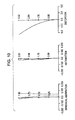
- Fig. 10 illustrates aberration diagrams of spherical aberration, astigmatism and distortion at a wide-angle end state according to a third numerical example in which specific numerical values are applied to the zoom lens according to the third embodiment of the present invention;
- Fig. 11 illustrates aberration diagrams of spherical aberration, astigmatism and distortion at an intermediate zoom position according to the third numerical example;
- Fig. 12 illustrates aberration diagrams of spherical aberration, astigmatism and distortion at a telephoto end state according to the third numerical example;
- Fig. 13 is an illustration showing a lens arrangement of a zoom lens according to a fourth embodiment of the present invention;
- Fig. 14 illustrates aberration diagrams of spherical aberration, astigmatism and distortion at a wide-angle end state according to a fourth numerical example in which specific numerical values are applied to the zoom lens according to the fourth embodiment of the present invention;
- Fig. 15 illustrates aberration diagrams of spherical aberration, astigmatism and distortion at an intermediate zoom position according to the fourth numerical example;
- Fig. 16 illustrates aberration diagrams of spherical aberration, astigmatism and distortion at a telephoto end state according to the fourth numerical example; and
- Fig. 17 is a block diagram showing an image pickup apparatus according to an embodiment of the present invention.
- Exemplary embodiments of a zoom lens and an image pickup apparatus according to the present invention will be described below with reference to the attached drawings.
- A zoom lens according to an embodiment of the present invention includes a first lens group having a negative refractive power, a second lens group having a positive refractive power, and a third lens group having a positive refractive power, the lens groups being sequentially aligned from an object side. The first lens group is moved along an optical axis of the zoom lens, and the second lens group is moved along the optical axis toward the object side, during zooming from a wide-angle end state to a telephoto end state. The third lens group includes a negative sub-lens group having a negative refractive power, and a positive sub-lens group having a positive refractive power, the sub-lens groups being sequentially aligned from the object side. An image may be shifted by moving the positive sub-lens group in a direction orthogonal to the optical axis. Also, the following conditional expression (1) is satisfied,

where β is a magnification of the positive sub-lens group of the third lens group at the telephoto end state. - In the zoom lens according to the embodiment of the present invention, the final third lens group is divided into the positive sub-lens group and the negative sub-lens group, and the positive sub-lens group serves as an image stabilization lens group that is shifted in the direction orthogonal to the optical axis. With such an arrangement, an image stabilization driving system for shifting the image stabilization lens group may be disposed at a position closest to the image side, the area being relatively vacant. Accordingly, the interference between the image stabilization driving system and other driving systems, such as a shutter and iris unit driving system and a zoom driving system, may be minimized.
- Typically, zooming may be performed by using a first lens group, and the negative and positive sub-lens groups of the third lens group. In the zoom lens according to the embodiment of the present invention, the use of the negative sub-lens group for zooming may eliminate the interference between the zoom driving system and the image stabilization driving system, thereby promoting miniaturization of the zoom lens.
- The above-mentioned conditional expression (1) defines a proportion of a shift amount of an image in the direction orthogonal to the optical axis relative to a moving distance of the image stabilization lens group in the direction orthogonal to the optical axis. When a value is below the lower limit of the conditional expression (1), the moving distance of the image stabilization lens group necessary for shifting the image by a predetermined amount is increased. As a result, the driving system for shifting the image stabilization lens group becomes large, thereby resulting in an increase in size. When a value is above the upper limit of the conditional expression (1), since the shift amount of the image relative to the moving distance of the image stabilization lens group is increased as described above, the moving distance of the image stabilization lens group is necessary to be highly accurately controlled. Due to this, parts tolerance and assembly precision, as well as accurate control of a detecting system and a driving system are necessary, thereby being extremely high cost.
- In addition, with such a zoom lens, the image stabilization may be performed by entirely shifting the second lens group in the direction orthogonal to the optical axis. However, since the variation in magnification mainly relies upon the variation in magnification of the second lens group, the value may be above the upper limit of the conditional expression (1) especially at the telescope end state to attain a zoom ratio of 3 or higher. With the zoom lens according to the embodiment of the present invention, the image stabilization is performed by moving (shifting) the positive sub-lens group of the third lens group in the direction orthogonal to the optical axis. Since the variation in magnification of the positive sub-lens group is small, the zoom ratio may be 3 or higher without the value being above the upper limit of the conditional expression (1).
- In the zoom lens according to the embodiment of the present invention, the negative sub-lens group of the third lens group may satisfy the following conditional expression (2),

where Rn is a curvature radius of a lens surface closest to the image side of the negative sub-lens group of the third lens group, and fw is a focal length of the whole lens system at the wide-angle end state. - The conditional expression (2) defines a surface profile closest to the image side of the negative sub-lens group of the third lens group. When a value is below the lower limit of the conditional expression (2), i.e., when a curvature radius of a surface closest to the image side of the negative sub-lens group is decreased and an effect for diverging light beam emitted from the negative sub-lens group becomes small, the distance between the negative sub-lens group and the positive sub-lens group is necessary to be increased for providing effective telecentricity at the positive sub-lens group, and hence, it may be difficult to miniaturize the whole optical system. When the value is above the upper limit of the conditional expression (2), i.e., when the effect for diverging the light beam becomes too large, the power of the positive sub-lens group also becomes large. Accordingly, it may be difficult to correct spherical aberration and coma, and the aberration variance in the image stabilization becomes large.
- In the zoom lens according to the embodiment of the present invention, the positive sub-lens group of the third lens group may satisfy the following conditional expression (3),

where CF is a curvature radius of a lens surface closest to the object side of the positive sub-lens group of the third lens group, and CR is a curvature radius of a lens surface closest to the image side of the positive sub-lens group of the third lens group. - The conditional expression (3) defines a profile of the image stabilization lens group. When a value is below the lower limit of the conditional expression (3), i.e., when CF is relatively small, it may be difficult to correct distortion and variation in image plane occurring in the image stabilization. When the value is above the upper limit of the conditional expression (3), i.e., CF is relatively large, it may be difficult to miniaturize the optical system.
- In the zoom lens according to the embodiment of the present invention, the positive sub-lens group of the third lens group may include a positive lens. Accordingly, the load applied to a driving system for shifting the positive sub-lens group (image stabilization lens group) of the third lens group in the direction orthogonal to the optical axis may be reduced, thereby realizing the miniaturization of the driving system and reducing power consumption.
- Next, specific embodiments of the zoom lens according to the present invention, and numerical examples in which specific numerical values are applied to embodiments, will be described below.
- Note that the profile of an aspherical surface according to each numerical example is defined by the following first expression:

where x is a distance along the optical axis from a lens vertex, y is a height in a direction orthogonal to the optical axis, c is a paraxial curvature at the lens vertex, K is a conic constant, and Ai is an aspherical coefficient at an i-th order. - Each of zoom lenses according to the following four embodiments having an image stabilization function includes a first lens group G1 having a negative refractive power, a second lens group G2 having a positive refractive power, and a third lens group G3 having a positive refractive power, the lens groups being sequentially aligned from an object side. Each group is moved such that an airspace between the first lens group G1 and the second lens group G2 is decreased and an airspace between the second lens group G2 and the third lens group G3 is increased, during zooming from a wide-angle end state to a telephoto end state.
- Fig. 1 is an illustration showing a lens arrangement of a zoom lens 1 according to a first embodiment. A first lens group G1 includes a negative meniscus lens L1 having an aspherical surface at the image side and a convex surface at the object side, and a cemented lens of a negative meniscus lens L2 having a convex surface at the object side and a positive meniscus lens L3 having a concave surface at the image side, the lenses being sequentially aligned from the object side. A second lens group G2 includes a cemented lens of a biconvex lens L4 and a negative meniscus lens L5 having a convex surface at the image side, and a positive meniscus lens L6 having an aspherical surface at the image side and a convex surface at the object side, the lenses being sequentially aligned from the object side. A third lens group G3 includes a negative meniscus lens L7 having a convex surface at the object side, and a biconvex lens L8 having an aspherical surface at the object side, the lenses being sequentially aligned from the object side. In the third lens group G3, the negative meniscus lens L7 defines a negative sub-lens group G3n, and the biconvex lens L8 defines a positive sub-lens group G3p. As the positive sub-lens group G3p is shifted in a direction orthogonal to an optical axis x of the zoom lens 1, an image may be shifted.
- An aperture stop S is disposed between the negative meniscus lens L5 and the positive meniscus lens L6 of the second lens group G2. Filters FL, such as a low pass filter and an infrared cut filter, are disposed between the third lens group G3 and an image plane IMG.
- Table 1 shows specific values of a first numerical example in which specific numerical values are applied to the first embodiment. In the following tables for specific values, "Surface No." represents an i-th surface counted from the object side, "R" represents a paraxial curvature radius of the i-th surface, "D" represents an on-axis surface distance between the i-th surface and an i+ 1-th surface, "Nd" represents a refractive index of the surface relative to the d-line (λ = 587.6 nm), and "νd" represents an Abbe number of the surface relative to the d-line. In "R", "INF" represents that the surface is a flat surface, and "ASP" represents that the surface is an aspherical surface.
Table 1 Surface No. R D Nd νd 1 27.812 0.550 1.80610 40.7 2 7.738 ASP 3.752 3 241.733 1.274 1.74330 49.2 4 10.925 2.243 1.80518 25.5 5 54.912 D5 6 18.364 2.217 1.72916 54.7 7 -14.861 0.450 1.90366 29.5 8 -36.692 1.000 9 Aperture Stop 1.716 10 6.410 ASP 1.449 1.58913 61.3 11 20.266 D11 12 11.379 0.555 1.80518 25.5 13 4.729 6.013 14 8.829 ASP 1.657 1.48749 70.4 15 -97.206 D15 16 INF 2.300 1.51680 64.2 17 INF 0.700 18 INF 0.500 1.51680 64.2 19 INF 1.000 20 INF - A surface distance D5 between the first lens group G1 and the second lens group G2, a surface distance D11 between the second lens group G2 and the third lens group G3, and a surface distance D15 between the third lens group G3 and the filters FL, are varied, during zooming from the wide-angle end state to the telephoto end state. Table 2 shows values of the variable distances at a wide-angle end state (f = 5.50), an intermediate zoom position (f = 7.72), and a telephoto end state (f = 15.40), together with F-numbers Fno, focal lengths f and half-field angles ω.
Table 2 Fno. 2.84 3.11 4.03 f 5. 50 7.72 15.40 ω 33.43 25.09 13.12 D5 22.771 13.469 1.941 D11 1.914 2.163 3.348 D15 2.940 5.066 11.624 - A 2nd surface, a 10th surface, and a 14th surface each have an aspherical surface. Table 3 shows aspherical coefficients A4, A6, A8 and A10 at a 4th order, a 6th order, an 8th order and a 10th order of each surface, together with conic constants K. Note that in Table 3 and the following tables showing the aspherical coefficients, "E-i" represents an exponent based on 10, namely, it represents "10-i". For instance, "0.26029E-05" represents "0.26029×10⁻⁵".
Table 3 Surface No. 2 K=0.00000E+00 A4=-1.20866E-04 A6=-2.49428E-06 A8=2.30481E-08 A10=-.23179E-49 10 K=0.00000E+00 A4=-1.05604E-04 A6= 4.49991E-06 A8=1.72248E-07 A10=-1.05206E-08 14 K=0.00000E+00 A4=-1.42896E-04 A6=3.23388E-07 A8=-3.46717E-08 A10=8.34113E-10 - Figs. 2, 3 and 4 show aberration diagrams at infinity according to the first numerical example. Fig. 2 illustrates aberration diagrams at the wide-angle end state (f = 5.50), Fig. 3 illustrates aberration diagrams at the intermediate zoom position (f = 7.72), and Fig. 4 illustrates aberration diagrams at the telephoto end state (f = 15.40).
- In each of Figs. 2, 3 and 4, the spherical aberration curves are plotted by a solid line for the d-line, a broken line for the C-line, and a dotted-chain line for the g-line. The astigmatism curves are plotted by a solid line for a sagittal image surface, and a broken line for a meridional image surface.
- Fig. 5 is an illustration showing a lens arrangement of a zoom lens 2 according to a second embodiment. A first lens group G1 includes a negative meniscus lens L1 having an aspherical surface at the image side and a convex surface at the object side, and a positive meniscus lens L2 having a convex surface at the object side, the lenses being sequentially aligned from the object side. A second lens group G2 includes a cemented lens of a biconvex lens L3 and a negative meniscus lens L4 having a convex surface at the image side, and a positive meniscus lens L5 having an aspherical surface at the image side and a convex surface at the object side, the lenses being sequentially aligned from the object side. A third lens group G3 includes a negative meniscus lens L6 having a convex surface at the object side, and a biconvex lens L7 having an aspherical surface at the object side, the lenses being sequentially aligned from the object side. In the third lens group G3, the negative meniscus lens L6 defines a negative sub-lens group G3n, and the biconvex lens L7 defines a positive sub-lens group G3p. As the positive sub-lens group G3p is shifted in a direction orthogonal to an optical axis x of the zoom lens 2, an image may be shifted.
- An aperture stop S is disposed between the negative meniscus lens L4 and the positive meniscus lens L5 of the second lens group G2. Filters FL, such as a low pass filter and an infrared cut filter, are disposed between the third lens group G3 and an image plane IMG.
- Table 4 shows specific values of a second numerical example in which specific numerical values are applied to the second embodiment.
Table 4 Surface No. R D Nd νd 1 117.681 1.200 1.74330 49.2 2 6.852 ASP 3.885 3 14.860 1.227 1.92286 20.9 4 21.928 D4 5 16.611 2.185 1.71300 53.9 6 -15.213 0.450 1.83400 37.3 7 -42.322 1.000 8 INF 1.544 9 6.642 ASP 1.354 1.58913 61.3 10 24.423 D10 11 13.974 0.508 1.84666 23.8 12 5.032 6.268 13 10.513 ASP 2.253 1.51680 64.2 14 -38.596 D14 15 INF 2.300 1.51680 64.2 16 INF 0.700 17 INF 0.500 1.51680 64.2 18 INF 1.000 19 INF - A surface distance D4 between the first lens group G1 and the second lens group G2, a surface distance D10 between the second lens group G2 and the third lens group G3, and a surface distance D14 between the third lens group G3 and the filters FL, are varied, during zooming from the wide-angle end state to the telephoto end state. Table 5 shows values of the variable distances at a wide-angle end state (f = 5.80), an intermediate zoom position (f = 8.08), and a telephoto end state (f = 16.24), together with F-numbers Fno, focal lengths f and half-field angles ω.
Table 5 Fno. 2.89 3.14 4.00 f 5.80 8.08 16.24 ω 32.31 24.08 12.43 D4 24.165 14.007 1.000 D10 1.913 2.087 2.937 D14 2.550 4.691 11.690 - A 2nd surface, a 9th surface, and a 13th surface each have an aspherical surface. Table 6 shows aspherical coefficients A4, A6, A8 and A10 at a 4th order, a 6th order, an 8th order and a 10th order of each surface, together with conic constants K.
Table 6 Surface No. 2 K=0.00000E+00 A4=-1.20866E-04 A6=-2.49428E-06 A8=2.30481E-08 A10=-23179E-09 10 K=0.00000E+00 A4=-1.05604E-04 A6=-4.49991E-06 A8=1.72248E-07 A10=-1.05206E-08 14 K=0.00000E+00 A4=-1.42896E-04 A6=3.23388E-07 A8=-3.46717E-08 A10=8.34113E-10 - Figs. 6, 7 and 8 show aberration diagrams at infinity according to the second numerical example. Fig. 6 illustrates aberration diagrams at the wide-angle end state (f = 5.80), Fig. 7 illustrates aberration diagrams at the intermediate zoom position (f = 8.08), and Fig. 8 illustrates aberration diagrams at the telephoto end state (f = 16.24).
- In each of Figs. 6, 7 and 8, the spherical aberration curves are plotted by a solid line for the d-line, a broken line for the C-line, and a dotted-chain line for the g-line. The astigmatism curves are plotted by a solid line for a sagittal image surface, and a broken line for a meridional image surface.
- Fig. 9 is an illustration showing a lens arrangement of a zoom lens 3 according to a third embodiment. A first lens group G1 includes a negative meniscus lens L1 having an aspherical surface at the image side and a convex surface at the object side, and a cemented lens of a negative meniscus lens L2 having a convex surface at the object side and a positive meniscus lens L3 having a concave surface at the image side, the lenses being sequentially aligned from the object side. A second lens group G2 includes a cemented lens of a biconvex lens L4 and a negative meniscus lens L5 having a convex surface at the image side, and a positive meniscus lens L6 having an aspherical surface at the image side and a convex surface at the object side, the lenses being sequentially aligned from the object side. A third lens group G3 includes a negative meniscus lens L7 having a convex surface at the object side, and a biconvex lens L8 having an aspherical surface at the object side, the lenses being sequentially aligned from the object side. In the third lens group G3, the negative meniscus lens L7 defines a negative sub-lens group G3n, and the biconvex lens L8 defines a positive sub-lens group G3p. As the positive sub-lens group G3p is shifted in a direction orthogonal to an optical axis x of the zoom lens 3, an image may be shifted.
- An aperture stop S is disposed between the negative meniscus lens L4 and the positive meniscus lens L5 of the second lens group G2. Filters FL, such as a low pass filter and an infrared cut filter, are disposed between the third lens group G3 and an image plane IMG.
- Table 7 shows specific values of a third numerical example in which specific numerical values are applied to the third embodiment.
Table 7 Surface No. R D Nd νd 1 76.895 1.000 1.80610 40.7 2 8.722 ASP 4.205 3 19.151 1.254 1.74330 49.2 4 9.310 2.500 1.84666 23.8 5 17.568 D5 6 14.767 2.500 1.74330 49.2 7 -16.300 0.450 1.84666 23.8 8 -67.902 1.000 9 Aperture Stop 2.000 10 6.840 ASP 1.353 1.58913 61.3 11 23.683 D11 12 16.592 0.500 1.90366 29.5 13 5.281 5.460 14 8.626 ASP 2.242 1.48749 70.4 15 -149.678 D15 16 INF 2.300 1.51680 64.2 17 INF 0.700 18 INF 0.500 1.51680 64.2 19 INF 1.000 20 INF - A surface distance D5 between the first lens group G1 and the second lens group G2, a surface distance D11 between the second lens group G2 and the third lens group G3, and a surface distance D15 between the third lens group G3 and the filters FL, are varied, during zooming from the wide-angle end state to the telephoto end state. Table 8 shows values of the variable distances at a wide-angle end state (f = 5.45), an intermediate zoom position (f = 10.38), and a telephoto end state (f = 20.71), together with F-numbers Fno, focal lengths f and half-field angles ω.
Table 8 Fno. 2.90 3.56 4.88 f 5.45 10.38 20.71 ω 34.35 19.16 9.78 D5 27.966 10.810 1.195 D11 2.201 2.736 4.157 D15 2.589 7.216 15.548 - A 2nd surface, a 10th surface, and a 14th surface each have an aspherical surface. Table 9 shows aspherical coefficients A4, A6, A8 and A10 at a 4th order, a 6th order, an 8th order and a 10th order of each surface, together with conic constants K.
Table 9 Surface No. 2 K=0.00000E+00 A4=-1.16136E-04 A6=-1.42390E-06 A8=9.10122E-09 A10=-4.37520E-10 10 K=0.00000E+00 A4=-1.30241E-04 A6=-1.80468E-06 A8=-1.23733E-07 A10=2.71888E-09 14 K=0.00000E+00 A4=-1.83379E-04 A6=-1.79509E-06 A8=9.80836E-08 A10=-3.67018E-09 - Figs. 10, 11 and 12 show aberration diagrams at infinity according to the third numerical example. Fig. 10 illustrates aberration diagrams at the wide-angle end state (f = 5.45), Fig. 11 illustrates aberration diagrams at the intermediate zoom position (f = 10.38), and Fig. 12 illustrates aberration diagrams at the telephoto end state (f = 20.71).
- In each of Figs. 10, 11 and 12, the spherical aberration curves are plotted by a solid line for the d-line, a broken line for the C-line, and a dotted-chain line for the g-line. The astigmatism curves are plotted by a solid line for a sagittal image surface, and a broken line for a meridional image surface.
- In the third numerical example, the conditional expression (1) may be satisfied while a zoom ratio of 3.8 is provided. In addition, reliable characteristics similar to other numerical examples may be achieved.
- Fig. 13 is an illustration showing a lens arrangement of a zoom lens 4 according to a fourth embodiment. A first lens group G1 includes a negative meniscus lens L1 having an aspherical surface at the image side and a convex surface at the object side, and a cemented lens of a negative meniscus lens L2 having a convex surface at the object side and a positive meniscus lens L3 having a concave surface at the image side, the lenses being sequentially aligned from the object side. A second lens group G2 includes a cemented lens of a biconvex lens L4 and a biconcave lens L5, and a biconvex lens L6 having an aspherical surface at the object side, the lenses being sequentially aligned from the object side. A third lens group G3 includes a negative meniscus lens L7 having a convex surface at the object side, and a biconvex lens L8 having an aspherical surface at the object side, the lenses being sequentially aligned from the object side. In the third lens group G3, the negative meniscus lens L7 defines a negative sub-lens group G3n, and the biconvex lens L8 defines a positive sub-lens group G3p. As the positive sub-lens group G3p is shifted in a direction orthogonal to an optical axis x of the zoom lens 4, an image may be shifted.
- An aperture stop S is disposed between the biconcave lens L5 and the biconvex L6 of the second lens group G2. Filters FL, such as a low pass filter and an infrared cut filter, are disposed between the third lens group G3 and an image plane IMG.
- Table 10 shows specific values of a fourth numerical example in which specific numerical values are applied to the fourth embodiment.
Table 10 Surface No. R D Nd νd 1 220.116 1.700 1.76802 46.6 2 8.750 ASP 3.000 3 12.545 1.500 1.72825 28.3 4 8.690 3.000 1.92286 20.9 5 12.553 D5 6 7.839 2.500 1.71300 53.9 7 -89.977 1.000 1.84666 23.8 8 17.156 1.000 9 Aperture Stop 1.072 10 11.408 ASP 3.000 1. 58913 61.3 11 -91.089 D11 12 22.489 1.000 1. 63854 55.4 13 5.839 4.225 14 8.711 ASP 2.180 1.48749 70.4 15 -56.266 2.117 16 INF 2.300 1.51680 64.2 17 INF 0.700 18 INF 0.500 1.51680 64.2 19 INF 1.000 20 INF - A surface distance D5 between the first lens group G1 and the second lens group G2, and a surface distance D11 between the second lens group G2 and the third lens group G3, are varied, during zooming from the wide-angle end state to the telephoto end state. Table 11 shows values of the variable distances at a wide-angle end state (f = 5.49), an intermediate zoom position (f = 7.03), and a telephoto end state (f = 15.66), together with F-numbers Fno, focal lengths f and half-field angles ω.
Table 11 Fno. 2.89 3.11 4.31 f 5.49 7.03 15.66 ω 34.00 27.17 12.46 D5 28.000 20.275 5.091 D11 1.625 2.597 8.116 - A 2nd surface, a 10th surface, and a 14th surface each have an aspherical surface. Table 12 shows aspherical coefficients A4, A6, A8 and A10 at a 4th order, a 6th order, an 8th order and a 10th order of each surface, together with conic constants K.
Table 12 Surface No. 2 K=0.00000E+00 A4=-1.30402E-04 A6=-1.13744E-06 A8=1.42352E-08 A10=-4.82316E-10 10 K=0.00000E+00 A4=-5.49540E-04 A6=-9.31411E-06 A8=1.43193E-07 A10=-1.39597E-08 14 K=0.00000E+00 A4=-2.44021E-04 A6=2.16086E-05 A8=-9.46570E-07 A10=1.65544E-08 - Figs. 14, 15 and 16 show aberration diagrams at infinity according to the fourth numerical example. Fig. 14 illustrates aberration diagrams at the wide-angle end state (f = 5.49), Fig. 15 illustrates aberration diagrams at the intermediate zoom position (f = 7.03), and Fig. 16 illustrates aberration diagrams at the telephoto end state (f = 15.66).
- In each of Figs. 14, 15 and 16, the spherical aberration curves are plotted by a solid line for the d-line, a broken line for the C-line, and a dotted-chain line for the g-line. The astigmatism curves are plotted by a solid line for a sagittal image surface, and a broken line for a meridional image surface.
- In the fourth embodiment, while the third lens group G3 is fixed during zooming for simplifying the zoom mechanism, reliable characteristics similar to other embodiments may be attained.
- Table 13 shows values corresponding to the conditional expressions (1), (2) and (3) in relation to the above-described numerical examples.
Table 13 First Numerical Example Second Numerical Example Third Numerical Example Fourth Numerical Example Conditional Expression (1) 0.973 1.013 1.224 0.444 [0.3 < (1-βa) × βb <2] Conditional Expression (2) 0.860 0.915 0.960 1.062 [0.5 < Rn/fw < 1. 5] Conditional Expression (3) -0.833 -0.572 -0.891 -0,732 [-1.0 < (CF + CR) / (CF - CR) < 0] - Fig. 17 shows an image pickup apparatus according to an embodiment of the present invention.
- An
image pickup apparatus 10 includes azoom lens 20, animage pickup device 30 that converts an optical image produced by thezoom lens 20 into an electric signal, acamera shake detector 50 that detects shake of the main body of theimage pickup device 30, and an image stabilization controller that controls variation in position of an object image to be produced, by driving a driver to move the image stabilization lens group (G3p) of thezoom lens 20 in the direction orthogonal to the optical axis of thezoom lens 20 in accordance with the shake of the main body of theimage pickup device 30 detected by thecamera shake detector 50. For example, theimage pickup device 30 may employ a photoelectric converter, such as a CCD (Charge Coupled Device) or CMOS (Complementary Metal-Oxide Semiconductor). Thezoom lens 20 may employ the zoom lens according to the embodiments of the present invention. In Fig. 17, the zoom lens 1 according to the first embodiment shown in Fig. 1 is presented. However, it is obvious that thezoom lens 20 is not limited to the zoom lens 1 according to the first embodiment, and may be selected from the zoom lenses 2 to 4 according to the second to fourth embodiments, or other zoom lenses having a configuration not relied upon the embodiments described in this specification. - A control circuit 40 (CPU) calculates a shake angle for correcting the camera shake by using a signal from the
camera shake detector 50, for instance, a gyro sensor, that detects the shake of the main body of theimage pickup device 30. A driving unit 61 (driver) is operated through a driver circuit 60 (image stabilization controller) to move the image stabilization lens group G3p to a predetermined position corresponding to the calculated shake angle. Asensor 62 obtains position information of the image stabilization lens group G3p. The image information is input to thecontrol circuit 40 and is referred when an instruction signal is output to thedriver circuit 60. The above-describedimage pickup apparatus 10 may be any type of commercially available products. For example, theimage pickup apparatus 10 may be widely applied to a camera of a digital I/O apparatus, such as a digital still camera, a digital video camera, a mobile phone with a camera mounted therein, and a PDA (Personal Digital Assistant) with a camera mounted therein. - Note that the specific profiles, configurations, numerical values of each component described in the embodiments and numerical examples are merely examples for implementing the present invention, and the technical scope of the present invention is not limited by these examples.
- It should be understood by those skilled in the art that various modifications, combinations, sub-combinations and alterations may occur depending on design requirements and other factors insofar as they are within the scope of the appended claims or the equivalents thereof.
Claims (5)
- A zoom lens comprising:a first lens group (G1) having a negative refractive power;a second lens group (G2) having a positive refractive power; anda third lens group (G3) having a positive refractive power, whereinthe lens groups are sequentially aligned from an object side,
the first lens group (G1) is moved along an optical axis of the zoom lens and the second lens group (G2) is moved along the optical axis toward the object side, during zooming from a wide-angle end state to a telescopic end state,
the third lens group (G3) includes a negative sub-lens group (G3n) having a negative refractive power, and a positive sub-lens group (G3p) having a positive refractive power, the sub-lens groups being sequentially aligned from the object side, an image being able to be shifted by moving the positive sub-lens group (G3p) in a direction orthogonal to the optical axis, and
the following conditional expression (1) is satisfied,
where β is a magnification of the positive sub-lens group (G3p) of the third lens group (G3) at the telescopic end state. - The zoom lens according to claim 1, wherein
the negative sub-lens group (G3n) of the third lens group (G3) satisfies the following conditional expression (2),
where Rn is a curvature radius of a lens surface closest to an image side of the negative sub-lens group (G3n) of the third lens group (G3), and fw is a focal length of a whole lens system at a wide-angle end state. - The zoom lens according to claim 1, wherein
the positive sub-lens group (G3p) of the third lens group (G3) satisfies the following conditional expression (3),
where CF is a curvature radius of a lens surface closest to the object side of the positive sub-lens group (G3p) of the third lens group, and CR is a curvature radius of a lens surface closest to the image side of the positive sub-lens group (G3p) of the third lens group (G3). - The zoom lens according to claim 1, wherein the positive sub-lens group (G3p) of the third lens group (G3) includes a positive lens.
- An image pickup apparatus comprising:a zoom lens according to any one of claims 1 to 4; andan image pickup device that converts an optical image produced by the zoom lens into an electric signal.
Applications Claiming Priority (1)
| Application Number | Priority Date | Filing Date | Title |
|---|---|---|---|
| JP2006054661A JP2007233045A (en) | 2006-03-01 | 2006-03-01 | Zoom lens and imaging device |
Publications (2)
| Publication Number | Publication Date |
|---|---|
| EP1830212A2 true EP1830212A2 (en) | 2007-09-05 |
| EP1830212A3 EP1830212A3 (en) | 2010-03-31 |
Family
ID=38016841
Family Applications (1)
| Application Number | Title | Priority Date | Filing Date |
|---|---|---|---|
| EP07103204A Withdrawn EP1830212A3 (en) | 2006-03-01 | 2007-02-28 | Zoom lens and image pickup apparatus |
Country Status (4)
| Country | Link |
|---|---|
| US (1) | US7468841B2 (en) |
| EP (1) | EP1830212A3 (en) |
| JP (1) | JP2007233045A (en) |
| CN (1) | CN100451721C (en) |
Families Citing this family (13)
| Publication number | Priority date | Publication date | Assignee | Title |
|---|---|---|---|---|
| JP5418884B2 (en) * | 2009-03-17 | 2014-02-19 | 株式会社リコー | Imaging optical system, camera device, and portable information terminal device |
| JP5387139B2 (en) * | 2009-05-25 | 2014-01-15 | 株式会社リコー | Imaging lens, camera device, and portable information terminal device |
| JP2011059293A (en) * | 2009-09-09 | 2011-03-24 | Sigma Corp | Variable imaging optical system |
| JP5676505B2 (en) | 2011-04-07 | 2015-02-25 | パナソニックIpマネジメント株式会社 | Zoom lens system, imaging device and camera |
| JP5868275B2 (en) | 2012-06-29 | 2016-02-24 | キヤノン株式会社 | Zoom lens and imaging apparatus having the same |
| WO2014103200A1 (en) * | 2012-12-26 | 2014-07-03 | 富士フイルム株式会社 | Image pickup lens and image pickup device provided with same |
| WO2016121939A1 (en) * | 2015-01-30 | 2016-08-04 | 株式会社ニコン | Variable power optical system, optical device, and method for producing variable power optical system |
| WO2016121945A1 (en) * | 2015-01-30 | 2016-08-04 | 株式会社ニコン | Variable power optical system, optical device, and method for producing variable power optical system |
| CN106249391B (en) | 2015-06-05 | 2019-07-09 | 佳能株式会社 | Zoom lens and image pick-up device including zoom lens |
| KR102620545B1 (en) * | 2016-04-06 | 2024-01-03 | 삼성전기주식회사 | Optical Imaging System |
| CN113156632B (en) * | 2021-05-06 | 2025-06-06 | 浙江舜宇光学有限公司 | A zoom lens |
| CN113495347B (en) * | 2021-09-07 | 2021-12-07 | 沂普光电(天津)有限公司 | Ultra-short-focus lens |
| CN114488491B (en) * | 2022-03-07 | 2022-10-28 | 浙江大学 | Large-aperture laser direct writing objective lens |
Family Cites Families (20)
| Publication number | Priority date | Publication date | Assignee | Title |
|---|---|---|---|---|
| JPS5232342A (en) * | 1975-09-08 | 1977-03-11 | Canon Inc | Variable magnification optical unit |
| JPS6042451B2 (en) * | 1981-12-07 | 1985-09-21 | マミヤ光機株式会社 | wide angle zoom lens |
| US4726667A (en) * | 1984-10-19 | 1988-02-23 | Asahi Kogaku Kogyo Kabushiki Kaisha | Focusing method in optical lens system with variable focal length |
| JPS6243614A (en) * | 1985-08-22 | 1987-02-25 | Canon Inc | Rear focus zoom lens |
| JPH0593858A (en) * | 1991-04-09 | 1993-04-16 | Konica Corp | Small-sized zoom lens |
| JP3162114B2 (en) * | 1991-07-24 | 2001-04-25 | オリンパス光学工業株式会社 | Two-group zoom lens |
| JP3359131B2 (en) * | 1993-11-04 | 2002-12-24 | キヤノン株式会社 | Variable power optical system with anti-vibration function |
| JPH08101361A (en) * | 1994-09-29 | 1996-04-16 | Nikon Corp | Zoom lens that can shift image |
| JP3590807B2 (en) * | 1995-03-08 | 2004-11-17 | 株式会社ニコン | Zoom lens |
| JP3570697B2 (en) * | 1995-10-05 | 2004-09-29 | 富士写真光機株式会社 | 3-group zoom lens |
| JPH09211327A (en) * | 1996-01-31 | 1997-08-15 | Nikon Corp | Zoom lens |
| JPH1090599A (en) * | 1996-09-12 | 1998-04-10 | Nikon Corp | Zoom lens with anti-vibration function |
| JPH10161023A (en) * | 1996-11-28 | 1998-06-19 | Minolta Co Ltd | Zoom lens having camera shake correcting function |
| JPH11174329A (en) * | 1997-12-15 | 1999-07-02 | Canon Inc | Variable power optical system with anti-vibration function |
| WO2001025833A1 (en) * | 1999-10-07 | 2001-04-12 | Matsushita Electric Industrial Co., Ltd. | Zoom lens and video camera comprising the same |
| JP4138671B2 (en) * | 2002-04-11 | 2008-08-27 | 松下電器産業株式会社 | Zoom lens and electronic still camera using the same |
| KR20050035541A (en) * | 2002-09-10 | 2005-04-18 | 마쯔시다덴기산교 가부시키가이샤 | Shaking correction function-mounted zoom lens |
| JP2004333572A (en) * | 2003-04-30 | 2004-11-25 | Nikon Corp | Variable focal length lens system |
| US7199941B2 (en) * | 2003-10-29 | 2007-04-03 | Sony Corporation | Zoom lens |
| JP2005284063A (en) * | 2004-03-30 | 2005-10-13 | Fujinon Corp | Four-group zoom lens with vibration-proof function |
-
2006
- 2006-03-01 JP JP2006054661A patent/JP2007233045A/en active Pending
-
2007
- 2007-02-28 EP EP07103204A patent/EP1830212A3/en not_active Withdrawn
- 2007-02-28 US US11/711,761 patent/US7468841B2/en not_active Expired - Fee Related
- 2007-03-01 CN CNB2007100923473A patent/CN100451721C/en not_active Expired - Fee Related
Also Published As
| Publication number | Publication date |
|---|---|
| CN100451721C (en) | 2009-01-14 |
| US20070206294A1 (en) | 2007-09-06 |
| JP2007233045A (en) | 2007-09-13 |
| US7468841B2 (en) | 2008-12-23 |
| EP1830212A3 (en) | 2010-03-31 |
| CN101038368A (en) | 2007-09-19 |
Similar Documents
| Publication | Publication Date | Title |
|---|---|---|
| US7468841B2 (en) | Zoom lens and image pickup apparatus | |
| US10222594B2 (en) | Zoom lens and image pickup apparatus including the same | |
| US7894135B2 (en) | Zoom lens and image pickup apparatus including the lens | |
| JP4604303B2 (en) | Variable focal length lens system and imaging apparatus including the lens system | |
| US7515353B2 (en) | Zoom lens system and camera including zoom lens system | |
| EP2360504B1 (en) | Zoom lens system, optical apparatus and method for manufacturing zoom lens system | |
| US7688520B2 (en) | Zoom lens system and camera including the same | |
| JP4317928B2 (en) | Zoom lens | |
| JP6192338B2 (en) | Zoom lens and imaging apparatus having the same | |
| US8107171B2 (en) | Zoom lens system and image pickup apparatus including the same | |
| US8437090B2 (en) | Zoom lens and image pickup apparatus including the same | |
| US7486448B2 (en) | Zoom lens and image pickup apparatus | |
| EP2533091A2 (en) | Zoom lens and image pickup apparatus equipped with zoom lens | |
| US8085478B2 (en) | Zoom lens system and image pickup apparatus including the same | |
| CN109239896B (en) | Zoom lens and image pickup apparatus | |
| EP1870760A1 (en) | Retrofocus type of zoom lens having four lens groups | |
| JP4374222B2 (en) | Variable magnification optical system | |
| EP1865351A1 (en) | Telephoto-type zoom lens comprising four lens groups with rear-focusing | |
| JP2011133740A (en) | Zoom lens and imaging apparatus including the same | |
| US9726866B2 (en) | Zoom lens and image pickup device including the same | |
| JP2009282465A (en) | Zoom lens and imaging apparatus | |
| JP5939788B2 (en) | Zoom lens and imaging apparatus having the same | |
| US7457047B2 (en) | Zoom optical system and imaging apparatus using the same | |
| JP2005352183A (en) | Variable focal length lens system and imaging apparatus | |
| JP6808441B2 (en) | Zoom lens and imaging device with it |
Legal Events
| Date | Code | Title | Description |
|---|---|---|---|
| PUAI | Public reference made under article 153(3) epc to a published international application that has entered the european phase |
Free format text: ORIGINAL CODE: 0009012 |
|
| AK | Designated contracting states |
Kind code of ref document: A2 Designated state(s): AT BE BG CH CY CZ DE DK EE ES FI FR GB GR HU IE IS IT LI LT LU LV MC NL PL PT RO SE SI SK TR |
|
| AX | Request for extension of the european patent |
Extension state: AL BA HR MK YU |
|
| PUAL | Search report despatched |
Free format text: ORIGINAL CODE: 0009013 |
|
| AK | Designated contracting states |
Kind code of ref document: A3 Designated state(s): AT BE BG CH CY CZ DE DK EE ES FI FR GB GR HU IE IS IT LI LT LU LV MC NL PL PT RO SE SI SK TR |
|
| AX | Request for extension of the european patent |
Extension state: AL BA HR MK RS |
|
| AKY | No designation fees paid | ||
| REG | Reference to a national code |
Ref country code: DE Ref legal event code: 8566 |
|
| STAA | Information on the status of an ep patent application or granted ep patent |
Free format text: STATUS: THE APPLICATION IS DEEMED TO BE WITHDRAWN |
|
| 18D | Application deemed to be withdrawn |
Effective date: 20100901 |