EP1829733A2 - Vehicle seat, motor vehichle and airbag module - Google Patents
Vehicle seat, motor vehichle and airbag module Download PDFInfo
- Publication number
- EP1829733A2 EP1829733A2 EP07103312A EP07103312A EP1829733A2 EP 1829733 A2 EP1829733 A2 EP 1829733A2 EP 07103312 A EP07103312 A EP 07103312A EP 07103312 A EP07103312 A EP 07103312A EP 1829733 A2 EP1829733 A2 EP 1829733A2
- Authority
- EP
- European Patent Office
- Prior art keywords
- seat
- airbag
- airbag module
- vehicle
- bracket
- Prior art date
- Legal status (The legal status is an assumption and is not a legal conclusion. Google has not performed a legal analysis and makes no representation as to the accuracy of the status listed.)
- Granted
Links
Images





Classifications
-
- B—PERFORMING OPERATIONS; TRANSPORTING
- B60—VEHICLES IN GENERAL
- B60N—SEATS SPECIALLY ADAPTED FOR VEHICLES; VEHICLE PASSENGER ACCOMMODATION NOT OTHERWISE PROVIDED FOR
- B60N2/00—Seats specially adapted for vehicles; Arrangement or mounting of seats in vehicles
- B60N2/24—Seats specially adapted for vehicles; Arrangement or mounting of seats in vehicles for particular purposes or particular vehicles
- B60N2/42—Seats specially adapted for vehicles; Arrangement or mounting of seats in vehicles for particular purposes or particular vehicles the seat constructed to protect the occupant from the effect of abnormal g-forces, e.g. crash or safety seats
- B60N2/427—Seats or parts thereof displaced during a crash
- B60N2/42727—Seats or parts thereof displaced during a crash involving substantially rigid displacement
- B60N2/42754—Seats or parts thereof displaced during a crash involving substantially rigid displacement of the cushion
- B60N2/42763—Seats or parts thereof displaced during a crash involving substantially rigid displacement of the cushion with anti-submarining systems
-
- B—PERFORMING OPERATIONS; TRANSPORTING
- B60—VEHICLES IN GENERAL
- B60R—VEHICLES, VEHICLE FITTINGS, OR VEHICLE PARTS, NOT OTHERWISE PROVIDED FOR
- B60R21/00—Arrangements or fittings on vehicles for protecting or preventing injuries to occupants or pedestrians in case of accidents or other traffic risks
- B60R21/02—Occupant safety arrangements or fittings, e.g. crash pads
- B60R21/16—Inflatable occupant restraints or confinements designed to inflate upon impact or impending impact, e.g. air bags
- B60R21/20—Arrangements for storing inflatable members in their non-use or deflated condition; Arrangement or mounting of air bag modules or components
- B60R21/207—Arrangements for storing inflatable members in their non-use or deflated condition; Arrangement or mounting of air bag modules or components in vehicle seats
Definitions
- the present invention relates to a vehicle seat, and more in detail, to a construction technology for a vehicle seat, on which an airbag module having a construction in which an airbag is developed and expanded from a downside to an upside of a seat cushion against movement of a vehicle occupant toward a front side of the motor vehicle in a seating condition of the vehicle occupant in a vehicle seat when an accident occurs, is mounted.
- the present invention is constructed.
- the present invention can be applied to a construction technology for a vehicle seat mounted on various kinds of motor vehicles, such as automobile motor vehicles, trucks, buses, electric trains, boats and ships, and so fourth.
- the first aspect of the present invention for solving the aforementioned problems is a vehicle seat according to Claim 1.
- the vehicle seat according to Claim 1 is a vehicle seat mounted on a motor vehicle, and constructed to be provided with at least a left side frame, a right side frame, a bracket, a seat pan, an airbag module, and a together-fastening member.
- the left side frame according to the present invention is configured to be a seat frame component extending in a front and back direction at a left side below a seat cushion in a seat frame forming a skeleton of a seat.
- the right side frame according to the present invention is configured to be a seat frame component extending in the front and back direction at a right side below the seat cushion in the seat frame forming the skeleton of the seat.
- a bracket according to the present invention is configured to be a seat frame component for connecting the left side frame and the right side frame below the seat cushion in the seat frame forming the skeleton of the seat.
- the bracket and the left side frame, and the bracket and the right side frame are typically, connected by welding, fastening with a bolt and a nut, or the like.
- a seat pan according to the present invention is configured to have a construction being disposed between the left side frame and the right side frame below the seat cushion, and including an airbag module housing portion.
- the "seat pan” according to the present invention is defined as a member constituting a seat bottom surface of the vehicle seat, and specifically, can also be defined as a seat cushion panel, a seat cushion frame, or a seat cushion board receiving the seat cushion. With regard to a disposing configuration of the seat pan, it is sufficient that entire, or a part of the seat pan is disposed between the left side frame and the right side frame.
- a construction in which the seat pan is fixed to the left side frame and the right side frame by welding, fastening with a bolt and nut, or the like, in a manner so as to be hung across the side frames, or a construction in which the seat pan is fixed to a member situated between the left side frame and the right side frame by welding, fastening with a bolt and nut, or the like, can be adopted.
- the airbag module according to the present invention has a construction to be set such that the airbag module includes an airbag, and is housed in the airbag module housing portion, and the airbag is developed and expanded from a downside to an upside of the seat cushion against movement of a vehicle occupant in a condition of being seated in a vehicle seat, toward a front side of a motor vehicle when an accident occurs.
- the airbag module typically is mainly constructed with the airbag being folded back in a predetermined folding configuration and housed, a gas-supplying portion generating airbag-expansion gas and supplying the gas into the airbag when the accident occurs, a retainer for housing the gas-supplying portion.
- the airbag module can sometimes be also called as an "airbag apparatus" or an "occupant restraining apparatus".
- the together-fastening member according to the present invention is constructed to be a member for performing a together-fastening operation for the airbag module, the seat pan, and the bracket.
- the together-fastening operation is enabled by use of a fastening operation by a bolt and a nut, a swaging operation by a rivet, and so forth.
- pressure caused at the time when the airbag is developed and expanded when the accident occurs namely a load caused at the time when the airbag module is activated, is received by the seat pan and the bracket that are integrally formed by the together-fastening operation, by means of that the airbag module, the seat pan, and the bracket are fastened together and fixed by the together-fastening member.
- the strength of the seat pan can be raised by means of that a board thickness of the bracket that is fastened together and fixed to the seat pan is added to the board thickness of the seat pan, it is enabled to secure the strength required for the vehicle seat, upon suppressing the board thickness of the seat pan by this extent. Therefore, in accordance with the invention according to Claim 1, strength can be secured while aiming at weight saving for the vehicle seat by means of a cooperative work of the seat pan and the bracket.
- the airbag module according to Claim 1 at least includes an airbag, a gas-supplying portion, a retainer, and a fixing bolt.
- the gas-supplying portion in the present invention is provided with a function for generating airbag-expansion gas and supplying the gas into the airbag when the accident occurs.
- the gas-supplying portion is housed in the retainer according to the present invention.
- the fixing bolt according to the present invention constitutes the together-fastening member attached to the retainer.
- the fixing bolt may be formed in an integrally fixed manner with the retainer, or may be attached to the retainer in a condition of a separate body.
- the retainer, the seat pan, and the bracket are fastened together and fixed by means of fastening force of the fixing bolt in a condition in which the fixing bolt at the retainer side is inserted into a through-hole that penetrates through the seat pan and the bracket.
- the strength of the seat pan can further be raised by means of that a board thickness of the bracket that is fastened together and fixed to the seat pan is added to the board thickness of the seat pan, it is enabled to secure the strength required for the vehicle seat, upon further suppressing the board thickness of the seat pan by this extent. Therefore, in accordance with the invention according to Claim 2, strength can be secured while aiming at weight saving for the vehicle seat by means of a cooperative work of the retainer, the seat pan, and the bracket.
- the third aspect of the present invention for solving the aforementioned problems is the vehicle seat according to Claim 3.
- the vehicle seat according to Claim 3 is constructed such that in the construction according to Claim 2, an extending direction of the fixing bolt is approximately conformed to a developing direction of the airbag at the time when the airbag is developed and expanded. That is, when the accident occurs, the airbag is configured to be developed along an axial direction of the fixing bolt. According to such a construction described above, fastening force of the fixing bolt can effectively be used as the force opposing to the airbag's load at the time when the airbag is developed and expanded.
- the fourth aspect of the present invention for solving the aforementioned problems is the motor vehicle according to Claim 4.
- the motor vehicle according to Claim 4 at least includes a vehicle seat according to any one of Claims 1 through 3, and a seat belt for restraining the vehicle occupant seated in the vehicle seat. Further, in a seat belt wearing condition in which the seat belt is worn by the vehicle occupant seated in the vehicle seat, the construction is formed such that occurrence of a movement of the vehicle occupant to slip through a downside of a seat belt along a seat surface, along with a frontward movement of a waist portion of the vehicle occupant when an accident occurs, i.e., a so-called "submarine phenomenon" is blocked by means of the airbag module mounted on the vehicle seat. Therefore, in accordance with the invention according to Claim 4, a motor vehicle capable of securing strength while being aimed at weight saving for the vehicle seat is provided.
- the fifth aspect of the present invention for solving the aforementioned problems is the airbag module according to Claim 5.
- the airbag module according to Claim 5 has a construction substantially similar to the airbag module that serves as a component of the vehicle seat according to Claim 1. Therefore, in accordance with the invention according to Claim 5, an airbag module capable of being effectively used for securing the strength while being aimed at weight saving of the vehicle seat by means of a cooperative work of the seat pan and the bracket is provided.
- the sixth aspect of the present invention for solving the aforementioned problems is the airbag module according to Claim 6.
- the airbag module according to Claim 6 has a construction substantially similar to the airbag module that serves as a component of the vehicle seat according to Claim 2. Therefore, in accordance with the invention according to Claim 6, an airbag module capable of being effectively used for securing the strength while being aimed at weight saving of the vehicle seat by means of a cooperative work of the retainer, the seat pan and the bracket is provided.
- the seventh aspect of the present invention for solving the aforementioned problems is the airbag module according to Claim 7.
- the airbag module according to Claim 7 is constructed such that in the construction according to Claim 6, a developing direction of the airbag at a time when the airbag is developed and expanded is approximately conformed to an extending direction of a fixing bolt. That is, when the accident occurs, the airbag is developed along an axial direction of the fixing bolt. According to such a construction as described above, it is enabled for the fastening force of the fixing bolt to be efficiently used as the force opposing to an airbag load at a time when the airbag is developed and expanded.
- a vehicle seat on which an airbag module having a construction in which an airbag is developed and expanded from a downside to an upside of a seat cushion against a forward movement of a vehicle occupant in a seating condition in a vehicle seat toward a front side of a motor vehicle at a time of occurrence of an accident is mounted, it becomes enabled to secure the strength while aiming at weight saving for a vehicle seat, by constructing such that, specifically, the airbag module, a seat pan, and a bracket are fastened together and fixed, and pressure caused at a time when the airbag is developed and expanded when the accident occurs is received by the seat pan and the bracket that are integrally formed by being fastened together and fixed.
- the vehicle seat 100 is a vehicle seat to be mounted on a motor vehicle, and is mainly constructed of a seat frame 10, a seat pan 20, and an airbag module 30.
- the vehicle seat 100 is constructed to serve as a driver's seat where a driver is seated, or a passenger seat.
- a seatbelt (corresponds to a "seatbelt" in the present invention) to be worn by an occupant seated in the vehicle seat 100 is further mounted.
- FR front side of the motor vehicle
- UP represents an upside of the motor vehicle.
- the seat frame 10 is constructed to serve as a frame that forms a skeleton portion of the vehicle seat 100, and is at least provided with a base frame 12 and a back frame 14.
- the seat frame 10 corresponds to a "seat frame" in the present invention.
- a seat cushion (not shown) formed from a material having plasticity, such as a urethane material, or the like, is mounted, and the seat cushion constitutes a seat surface of the vehicle seat 100.
- a seat back (not shown) formed from a material having plasticity, such as a urethane material, or the like, is mounted, and the seat back constitutes a back surface of the vehicle seat 100.
- an outer surface of each of the seat cushion and the back seat is covered with scurf skin (not shown) formed from leather, cloth, or the like.
- the base frame 12 is a frame to be disposed below the seat cushion, and is provided with a left-and-right pair of side frames, 12a and 12b (a left side frame 12a, and a right side frame 12b), extending in a front and back direction of the vehicle seat 100 (conforming to a front and back direction of the motor vehicle).
- the left side frame 12a mentioned here corresponds to a "left side frame” in the present invention
- the right side frame 12b corresponds to a "right side frame” in the present invention.
- a bracket 13 for reinforcement is provided so as to hang across the left and right side frames, 12a and 12b.
- the bracket 13 is constructed to be a plate shape (a curved plate shape in Fig.
- This bracket 13 serves as a supporting member for supporting the seat pan 20, and is constructed to serve as a holding member for connecting and holding the left and right side frames, 12a and 12b.
- the bracket 13 also serves as a positioning member when joining the left and right side frames, 12a and 12b, resulting in providing a good assembling capability.
- This bracket 13 corresponds to a "bracket" in the present invention.
- the back frame 14 is a frame that is rotatably connected to the base frame 12 via a supporting shaft 15 and a reclining device (not shown). At an upper part of the back frame 14, a head rest 16 is attached to a position corresponding to a head portion of a vehicle occupant.
- the seat pan 20 is provided so as to hang across the left-and-right pair of the side frames, 12a and 12b in a manner so as to cover the same from above, at a portion above the bracket 13 and below the seat cushion.
- the seat pan 20 is a member constituting a seat bottom surface of the vehicle seat 100, and specifically, can also be defined as a seat cushion panel that receives the seat cushion, a seat cushion frame, or a seat cushion board.
- the seat pan 20 is attached to the bracket 13 by means of the fastening process with the bolt and nut at two places.
- the seat pan 20 can also be joined to the left and right side frames, 12a and 12b, by means of the welding process or the fastening process with the bolt and nut.
- the seat pan 20 has a function to receive a load from the seat cushion.
- the seat pan 20 corresponds to a "seat pan” in the present invention.
- a housing portion 21 for housing the airbag module 30 is provided in the seat pan 20.
- the housing portion 21 corresponds to an "airbag module housing portion” in the present invention.
- the housing portion 21 is constructed to have a hollow portion 23 (sometimes called as “concave portion”, “cavity portion”, or “concave area") that is downwardly hollowed.
- the hollow portion 23 is configured to be a portion where the airbag module 30 can be held by the hollow portion 23.
- the housing portion 21 is provided with a first extension portion 20a constituting a bottom surface of the hollow portion 23, and a second extension portion 20b extending to a rear side (right side in Fig. 2) in relation to the first extension portion 20a.
- a step portion is formed by means of a difference of elevation in an upper and lower direction between the first extension portion 20a and the second extension portion 20b.
- the construction is made such that the first extension portion 20a is extending at a portion lower than the second extension portion 20b. Further, the housing portion 21 is opened diagonally upward toward the backside.
- a developing direction (sometimes called "protruding direction") of an airbag (airbag 31 described later) of the airbag module 30 is configured to be a diagonally upward and backward direction, as a direction indicated by an arrow 40 in Fig. 2.
- a work for housing the airbag module 30 in the housing portion 21, and a work for attaching and fixing the airbag module 30 to a seat pan 20 side is aimed at facilitating by means of a holding function (or a positioning function) of the airbag module 30 provided by the hollow portion 23 that is caved downward.
- the airbag module 30 in the held condition is configured to be positioned at a front side in relation to the step portion between the first extension portion 20a and the second extension portion 20b. Accordingly, a protrusion of the airbag module 30 toward a second extension portion 20b side can be discriminated on the basis of a result of a visible confirmation between a first condition in which the airbag module 30 held by the hollow portion 23 covers the step portion and a second condition in which the covering operation is released.
- a case, in which an entire step portion or a part of the step portion cannot be visibly confirmed represents the first condition in which the airbag module 30 covers the step portion, and this results in that a rear end surface of the airbag module 30 is discriminated to be protruded out to the second extension portion 20b side across the step portion. At this moment, the airbag module 30 can be judged not to be located at a proper position.
- a case, in which the entire step portion can be visibly confirmed represents the second condition in which the airbag module 30 does not cover the step portion, and this results in that the rear end surface of the airbag module 30 is discriminated not to be protruded out to the second extension portion 20b side across the step portion.
- the airbag module 30 can be judged to be located at the proper position. By discriminating the protrusion of the airbag module 30 toward the second extension portion 20b side, it becomes to be enabled to prevent the airbag module 30 from being pinched by an airbag cover that covers the housing portion 21. With regard to visibility of the step portion, the visibility of the step portion can be aimed at being further improved by forming a colored line at the step portion.
- the housing portion 21 of the seat pan 20 in the present embodiment has a construction including a hollow portion 23 that is caved downward. Therefore, the airbag module 30 in the housed condition (non-operating time) is aimed at being protected. Further, an airbag cover (not shown) that covers the housing portion 21 in a condition, in which the airbag module 30 is housed therein, is mounted on the seat pan 20, and protection for the airbag module 30 in the condition being housed by the airbag cover is aimed at being further improved.
- the airbag module 30 at least includes an airbag 31, a gas generator (sometimes called as, inflator) 32, and a retainer 33.
- the airbag module 30 corresponds to an "airbag module" in the present invention.
- the airbag 31 is constructed as an airbag element that is folded back in a predetermined folding configuration and housed, and that is developed and expanded by gas generated by the gas generator 32 and supplied to the airbag element when an accident occurs.
- the airbag 31 is developed and expanded from a downside to an upside of a seat cushion against movement of a vehicle occupant toward a front side of the motor vehicle in a seating condition of the vehicle occupant in a vehicle seat when the accident occurs.
- a phenomenon i.e., a so-called submarine phenomenon, in which the vehicle occupant has a behavior to slip through a downside of a seatbelt along a seat surface, along with a frontward movement of a waist portion of the vehicle occupant when the accident occurs, is blocked or suppressed.
- the airbag 31 mentioned here corresponds to an “airbag” in the present invention, and a “gas-supplying portion” in the present invention is constructed by the gas generator 32.
- the retainer 33 is constructed to serve as a member for housing the gas generator 32.
- the retainer 33 corresponds to a "retainer" in the present invention.
- a fixing bolt 34 for attaching and fixing the airbag module 30 to the base frame 12 side is provided in the retainer 33.
- the airbag module 30 is attached and fixed to the base frame 12 side by means of the fixing bolt 34.
- the fixing bolt 34 is configured to be able to be inserted into a through-hole 22 penetrating through the seat pan 20 and the bracket 13 in a condition in which the airbag module 30 is housed in the housing portion 21 of the seat pan 20.
- the retainer 33, the seat pan 20, and the bracket 13 are integrally formed by being fixed to each other by being fastened together (sometimes called as “fixing by together-fastening") by fastening (screwing) the fixing bolt 34 penetrated through the through-hole 22, and the nut 36 with each other.
- the nut 36 may be constructed as a separate body from the bracket 13, or may have a construction in which the nut 36 is integrally jointed with the bracket 13. Further, a shape of a round hole, a long hole, a slit, or the like can appropriately be selected as the through-hole 22.
- the fixing bolt 34 mentioned here corresponds to a "together-fastening member" and a "fixing bolt” in the present invention.
- the present embodiment is constructed such that an extending direction of a bolt axis of the fixing bolt 34 is approximately conformed to a developing direction of the airbag 31 along a direction indicated by an arrow 40 in Fig. 2. According to such a construction, it is enabled that fastening force of the fixing bolt 34 is effectively used as force against an airbag load when the airbag is developed and expanded.
- FIG. 3 A work for housing the airbag module 30 in the present embodiment in the housing portion 21 of the seat pan 20, and a work for attaching and fixing the airbag module 30 to the seat pan 20 side will be explained referring to Figs. 3 through 6.
- Fig. 3 is a perspective view schematically showing the work for housing the airbag module 30 into the housing portion 21 of the seat pan 20.
- the airbag module 30 is moved to the housing portion 21 in a manner so as for the fixing bolt 34 at an airbag module 30 side to be headed to the housing portion 21 of the seat pan 20.
- any of Fig. 4 through Fig. 6 is a cross-section showing a process for attaching and fixing the airbag module 30 to the housing portion 21 of the seat pan 20.
- the airbag module 30 is inserted toward the hollow portion 23 (the first extension portion 20a) from above the seat pan 20, in a condition of being headed so as for a gas generator 32 side to be situated at a downside. At this time, the airbag module 30 can be easily introduced into the hollow portion 23 along a concaved shape of the hollow portion 23. Thus, a provisionally held condition of the airbag module 30 shown in Fig. 5 is formed. At this moment, the bolt axis of the fixing bolt 34 is extended approximately in a left-and-right direction.
- the airbag module 30 is rotated in a direction indicated by an arrow 41 in Fig. 5 around the step portion as a pivot fulcrum, in a condition in which a module lower portion 35 of the airbag module 30 in a provisionally held condition is in contact with the step portion between the first extension portion 20a and the second extension portion 20b.
- the fixing bole 34 is caused to be in close contact with the through-hole 22 by the rotation.
- an inserting condition where the fixing bolt 34 is inserted into the through-hole 22 is formed, as shown in Fig. 6.
- occurrence of an abnormal noise due to contact or the like of the seat pan 20 and the bracket 13 can be prevented by fastening and fixing together, and seating comfortableness of the vehicle seat 100 can be improved by raising the strength of the seat pan 20.
- the seat pan 20 is constructed to be fixed to the bracket 13 by together fastening and fixing, and the seat pan 20 is not required to be fixed to the left side frame 12a and the right side frame 12b by welding or the like, a manufacturing process of the vehicle seat 100 can be simplified.
- the work for attaching and fixing the airbag module 30 to the seat pan 20 side is facilitated.
- the module lower portion 35 of the airbag module 30 held by the hollow portion 23 is caused to come into contact with the step portion between the first extension portion 20a and the second extension portion 20b from beginning to end during the time until the airbag module 30 is fastened to the seat pan 20 side by means of the fixing bolt 34. Since the airbag module 30 is thereby positioned, it is enabled to aim at improving an assembling capability of the airbag module 30.
- the present invention is not limited to the aforementioned embodiment, and various applications and modifications are considered.
- the following each embodiment, to which the aforementioned embodiment is applied, can be performed.
- the construction of the seat pan in the present invention can appropriately be changed as needed.
- each embodiment shown in Fig. 7 through Fig. 9 can also be adopted.
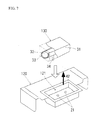
- Fig. 7 is a perspective view showing a construction of a seat pan 120 and an airbag module 130 in another embodiment.
- a housing portion 121 that houses the airbag module 130 is constructed to open upward.
- the fixing bolt 34 is attached to a lower portion of the retainer 33. Accordingly, the airbag module 130 is inserted from above the housing portion 121 in a condition in which the fixing bolt 34 is facing downward, and the fixing bolt 34 is inserted into the through-hole 22 and fastened. Thereby, the airbag module 130 is attached to a seat pan 120 side and fixed thereto.
- a developing direction of the airbag 31 that is developed and expanded when the accident occurs is an upside of the motor vehicle as shown by an arrow 42 in Fig. 7, and this direction is approximately conformed to an extending direction of the bolt axis of the fixing bolt 34.
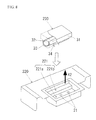
- Fig. 8 is a perspective view showing a construction of a seat pan 220 and an airbag module 230 in still another embodiment.
- a housing portion 221 that houses the airbag module 230 is constructed to open upward.
- the housing portion 221 is configured to have a stepped structure where a difference of elevation is applied to, in relation to an upper and lower direction, and a position that is relatively deep in depth is configured to be a first housing area 221a for housing the retainer 33, and a position relatively shallow in depth is configured to be a second housing area 221b for housing the portion of the airbag 31 situated above the retainer 33 in relation to the retainer 33.
- the fixing bolt 34 is attached to the lower portion of the retainer 33. Accordingly, the airbag module 230 is inserted from above the housing portion 221 in the condition in which the fixing bolt 34 is facing downward, and the fixing bolt 34 is inserted into the through-hole 22 and fastened. Thereby, the airbag module 230 is attached to a seat pan 220 side and fixed thereto.
- a developing direction of the airbag 31 that is developed and expanded when the accident occurs is an upside of the motor vehicle as shown by an arrow 42 in Fig. 8, and this direction is approximately conformed to an extending direction of the bolt axis of the fixing bolt 34.
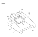
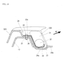
- Fig. 9 is a perspective view showing a construction of a seat pan 320 and an airbag module 330 in a further embodiment
- Fig. 10 is a cross-section along a line B-B in Fig. 9.
- the seat pan 320 in the embodiment shown in Fig. 9 is provided with the housing portion 21 similar to that in the seat pan 20, and the seat pan 320 is constructed to be further provided with a left-and-right pair of housing portions, 24 and 24.
- a left-and-right pair of brackets for bolt, 33a and 33a is provided in the retainer 33.
- Each bracket for bolt 33a is fastened together and fixed to the seat pan 320 and the bracket 13 by means of the fixing bolt 34 and the nut 36 in a condition of being housed in each housing portion 24.
- a developing direction of the airbag 31 that is developed and expanded when the accident occurs is configured to be a diagonally upward toward the backside direction as shown by an arrow 40 in Fig. 10, similar to that of a case of the airbag module 30.
- Fig. 11 is a perspective view schematically showing a work for housing the airbag module 330 into the housing portion 21 of the seat pan 320.
- the airbag module 330 is moved to the housing portion 21 in a manner so as for the fixing bolt 34 at the airbag module 330 side to be headed toward the housing portion 24 of the seat pan 320.
- the fixing bolt 34 and the nut 36 are fastened to each other.
- a condition, in which the retainer 33, the seat pan 320, and the bracket 13 are fastened together and fixed, is formed.
- bracket 13 constructed to be a plate shape having a predetermined board thickness (curved plate shape in Fig. 1) is described, a structure of a member corresponding to the bracket 13 is not limited thereto, and is able to be changed into various types of the bracket as needed.
- a construction member in which a through-hole for together-fastening is formed in a member, in which a cylindrically formed pipe-shaped member is pressed into a flat plate shape, a construction member in which a through-hole for together-fastening is formed in a plate-shaped member hung across a plurality of pipe-shaped member, a construction member in which a through-hole for together-fastening is formed in a member that is squeezed into a box-shape, or formed into a box-shape by bending processing, and so forth can also be used as a substitute member for the bracket 13.
- the construction may be formed such that the developing direction of the airbag and the extending direction of the fixing bolt intersect.
- the characteristic part of the present invention can also be applied to a construction of various types of vehicle seats including the driver's seat or a passenger seat, for example, a rear seat.
- various types of motor vehicles moving with vehicle occupants taken on such as automobiles, airplanes, boats and ships, electric trains, buses, trucks, and so forth are included.
Landscapes
- Engineering & Computer Science (AREA)
- Aviation & Aerospace Engineering (AREA)
- Transportation (AREA)
- Mechanical Engineering (AREA)
- Air Bags (AREA)
- Seats For Vehicles (AREA)
Abstract
Description
- The present invention relates to a vehicle seat, and more in detail, to a construction technology for a vehicle seat, on which an airbag module having a construction in which an airbag is developed and expanded from a downside to an upside of a seat cushion against movement of a vehicle occupant toward a front side of the motor vehicle in a seating condition of the vehicle occupant in a vehicle seat when an accident occurs, is mounted.
- Hitherto, in a seat belt-wearing condition in which a seat belt is worn by a vehicle occupant seated in a vehicle seat, various technologies for blocking occurrence of a phenomenon, i.e., a so-called "submarine phenomenon", in which the vehicle occupant has a behavior to slip through a downside of a seat belt along a seat surface, along with a frontward movement of a waist portion of the vehicle occupant when an accident occurs, is proposed. For example, in
JP-A-5-229378 - Accordingly, it is a problem in the present invention to provide a technology effective for securing strength while saving weight of a vehicle seat on which an airbag module having a construction in which an airbag is developed and expanded from a downside to an upside of a seat cushion against movement of a vehicle occupant in a seating condition in a vehicle seat toward a front side of the motor vehicle when an accident occurs, is mounted.
- To solve the aforementioned problems, the present invention is constructed. Incidentally, the present invention can be applied to a construction technology for a vehicle seat mounted on various kinds of motor vehicles, such as automobile motor vehicles, trucks, buses, electric trains, boats and ships, and so fourth.
- The first aspect of the present invention for solving the aforementioned problems is a vehicle seat according to Claim 1. The vehicle seat according to Claim 1 is a vehicle seat mounted on a motor vehicle, and constructed to be provided with at least a left side frame, a right side frame, a bracket, a seat pan, an airbag module, and a together-fastening member.
- The left side frame according to the present invention is configured to be a seat frame component extending in a front and back direction at a left side below a seat cushion in a seat frame forming a skeleton of a seat. The right side frame according to the present invention is configured to be a seat frame component extending in the front and back direction at a right side below the seat cushion in the seat frame forming the skeleton of the seat. A bracket according to the present invention is configured to be a seat frame component for connecting the left side frame and the right side frame below the seat cushion in the seat frame forming the skeleton of the seat. The bracket and the left side frame, and the bracket and the right side frame are typically, connected by welding, fastening with a bolt and a nut, or the like.
- A seat pan according to the present invention is configured to have a construction being disposed between the left side frame and the right side frame below the seat cushion, and including an airbag module housing portion. The "seat pan" according to the present invention is defined as a member constituting a seat bottom surface of the vehicle seat, and specifically, can also be defined as a seat cushion panel, a seat cushion frame, or a seat cushion board receiving the seat cushion. With regard to a disposing configuration of the seat pan, it is sufficient that entire, or a part of the seat pan is disposed between the left side frame and the right side frame. A construction in which the seat pan is fixed to the left side frame and the right side frame by welding, fastening with a bolt and nut, or the like, in a manner so as to be hung across the side frames, or a construction in which the seat pan is fixed to a member situated between the left side frame and the right side frame by welding, fastening with a bolt and nut, or the like, can be adopted.
- The airbag module according to the present invention has a construction to be set such that the airbag module includes an airbag, and is housed in the airbag module housing portion, and the airbag is developed and expanded from a downside to an upside of the seat cushion against movement of a vehicle occupant in a condition of being seated in a vehicle seat, toward a front side of a motor vehicle when an accident occurs. The airbag module typically is mainly constructed with the airbag being folded back in a predetermined folding configuration and housed, a gas-supplying portion generating airbag-expansion gas and supplying the gas into the airbag when the accident occurs, a retainer for housing the gas-supplying portion. The airbag module can sometimes be also called as an "airbag apparatus" or an "occupant restraining apparatus".
- The together-fastening member according to the present invention is constructed to be a member for performing a together-fastening operation for the airbag module, the seat pan, and the bracket. Typically, the together-fastening operation is enabled by use of a fastening operation by a bolt and a nut, a swaging operation by a rivet, and so forth. Further, in the present invention, pressure caused at the time when the airbag is developed and expanded when the accident occurs, namely a load caused at the time when the airbag module is activated, is received by the seat pan and the bracket that are integrally formed by the together-fastening operation, by means of that the airbag module, the seat pan, and the bracket are fastened together and fixed by the together-fastening member.
- According to the construction described above, since the strength of the seat pan can be raised by means of that a board thickness of the bracket that is fastened together and fixed to the seat pan is added to the board thickness of the seat pan, it is enabled to secure the strength required for the vehicle seat, upon suppressing the board thickness of the seat pan by this extent.
Therefore, in accordance with the invention according to Claim 1, strength can be secured while aiming at weight saving for the vehicle seat by means of a cooperative work of the seat pan and the bracket. - The second aspect of the present invention for solving the aforementioned problems is the vehicle seat according to Claim 2. In the vehicle seat according to Claim 2, the airbag module according to Claim 1 at least includes an airbag, a gas-supplying portion, a retainer, and a fixing bolt. The gas-supplying portion in the present invention is provided with a function for generating airbag-expansion gas and supplying the gas into the airbag when the accident occurs. The gas-supplying portion is housed in the retainer according to the present invention. The fixing bolt according to the present invention constitutes the together-fastening member attached to the retainer. The fixing bolt may be formed in an integrally fixed manner with the retainer, or may be attached to the retainer in a condition of a separate body. Further, in the present invention, the retainer, the seat pan, and the bracket are fastened together and fixed by means of fastening force of the fixing bolt in a condition in which the fixing bolt at the retainer side is inserted into a through-hole that penetrates through the seat pan and the bracket.
- According to the construction described above, since the strength of the seat pan can further be raised by means of that a board thickness of the bracket that is fastened together and fixed to the seat pan is added to the board thickness of the seat pan, it is enabled to secure the strength required for the vehicle seat, upon further suppressing the board thickness of the seat pan by this extent.
Therefore, in accordance with the invention according to Claim 2, strength can be secured while aiming at weight saving for the vehicle seat by means of a cooperative work of the retainer, the seat pan, and the bracket. - The third aspect of the present invention for solving the aforementioned problems is the vehicle seat according to Claim 3. The vehicle seat according to Claim 3 is constructed such that in the construction according to Claim 2, an extending direction of the fixing bolt is approximately conformed to a developing direction of the airbag at the time when the airbag is developed and expanded. That is, when the accident occurs, the airbag is configured to be developed along an axial direction of the fixing bolt. According to such a construction described above, fastening force of the fixing bolt can effectively be used as the force opposing to the airbag's load at the time when the airbag is developed and expanded.
- The fourth aspect of the present invention for solving the aforementioned problems is the motor vehicle according to Claim 4. The motor vehicle according to Claim 4 at least includes a vehicle seat according to any one of Claims 1 through 3, and a seat belt for restraining the vehicle occupant seated in the vehicle seat. Further, in a seat belt wearing condition in which the seat belt is worn by the vehicle occupant seated in the vehicle seat, the construction is formed such that occurrence of a movement of the vehicle occupant to slip through a downside of a seat belt along a seat surface, along with a frontward movement of a waist portion of the vehicle occupant when an accident occurs, i.e., a so-called "submarine phenomenon" is blocked by means of the airbag module mounted on the vehicle seat.
Therefore, in accordance with the invention according to Claim 4, a motor vehicle capable of securing strength while being aimed at weight saving for the vehicle seat is provided. - The fifth aspect of the present invention for solving the aforementioned problems is the airbag module according to Claim 5. The airbag module according to Claim 5 has a construction substantially similar to the airbag module that serves as a component of the vehicle seat according to Claim 1.
Therefore, in accordance with the invention according to Claim 5, an airbag module capable of being effectively used for securing the strength while being aimed at weight saving of the vehicle seat by means of a cooperative work of the seat pan and the bracket is provided. - The sixth aspect of the present invention for solving the aforementioned problems is the airbag module according to Claim 6. The airbag module according to Claim 6 has a construction substantially similar to the airbag module that serves as a component of the vehicle seat according to Claim 2.
Therefore, in accordance with the invention according to Claim 6, an airbag module capable of being effectively used for securing the strength while being aimed at weight saving of the vehicle seat by means of a cooperative work of the retainer, the seat pan and the bracket is provided. - The seventh aspect of the present invention for solving the aforementioned problems is the airbag module according to Claim 7. The airbag module according to Claim 7 is constructed such that in the construction according to Claim 6, a developing direction of the airbag at a time when the airbag is developed and expanded is approximately conformed to an extending direction of a fixing bolt. That is, when the accident occurs, the airbag is developed along an axial direction of the fixing bolt. According to such a construction as described above, it is enabled for the fastening force of the fixing bolt to be efficiently used as the force opposing to an airbag load at a time when the airbag is developed and expanded.
- As described above, according to the present invention, in a vehicle seat, on which an airbag module having a construction in which an airbag is developed and expanded from a downside to an upside of a seat cushion against a forward movement of a vehicle occupant in a seating condition in a vehicle seat toward a front side of a motor vehicle at a time of occurrence of an accident is mounted, it becomes enabled to secure the strength while aiming at weight saving for a vehicle seat, by constructing such that, specifically, the airbag module, a seat pan, and a bracket are fastened together and fixed, and pressure caused at a time when the airbag is developed and expanded when the accident occurs is received by the seat pan and the bracket that are integrally formed by being fastened together and fixed.
- Hereinbelow, an embodiment of the present invention will be explained in detail referring to the drawings.
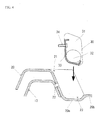
- Fig. 1
- is a view showing an internal structure of a
vehicle seat 100 in the present embodiment and is a perspective view looking from diagonal backside of the motor vehicle; - Fig. 2
- is a cross-section along a line A-A in Fig. 1;
- Fig. 3
- is a perspective view schematically showing a work for housing an
airbag module 30 into ahousing portion 21 of aseat pan 20; - Fig. 4
- is a cross-section showing a process for attaching and fixing the
airbag module 30 into thehousing portion 21 of theseat pan 20; - Fig. 5
- is a cross-section showing a process for attaching and fixing the
airbag module 30 into thehousing portion 21 of theseat pan 20; - Fig. 6
- is a cross-section showing the process for attaching and fixing the
airbag module 30 into thehousing portion 21 of theseat pan 20; - Fig. 7
- is a perspective view showing a construction of a
seat pan 120 and anairbag module 130 in another embodiment; - Fig. 8
- is a perspective view showing a construction of a
seat pan 220 and anairbag module 230 in still another embodiment; - Fig. 9
- is a perspective view showing a construction of a
seat pan 320 and anairbag module 330 in a further embodiment; - Fig. 10
- is a cross-section along a line B-B in Fig. 9; and
- Fig. 11
- is a perspective view schematically showing a work for housing the
airbag module 330 into thehousing portion 21 of theseat pan 320. - As shown in Fig. 1, the
vehicle seat 100 according to the present embodiment is a vehicle seat to be mounted on a motor vehicle, and is mainly constructed of aseat frame 10, aseat pan 20, and anairbag module 30. Thevehicle seat 100 is constructed to serve as a driver's seat where a driver is seated, or a passenger seat. Further, in the motor vehicle on which thevehicle seat 100 is mounted, a seatbelt (corresponds to a "seatbelt" in the present invention) to be worn by an occupant seated in thevehicle seat 100 is further mounted. Incidentally, a direction indicated by "FR" in Fig. 1 represents a front side of the motor vehicle, and that indicated by "UP" represents an upside of the motor vehicle. - The
seat frame 10 is constructed to serve as a frame that forms a skeleton portion of thevehicle seat 100, and is at least provided with abase frame 12 and aback frame 14. Theseat frame 10 corresponds to a "seat frame" in the present invention. On thebase frame 12, a seat cushion (not shown) formed from a material having plasticity, such as a urethane material, or the like, is mounted, and the seat cushion constitutes a seat surface of thevehicle seat 100. Further, on theback frame 14, a seat back (not shown) formed from a material having plasticity, such as a urethane material, or the like, is mounted, and the seat back constitutes a back surface of thevehicle seat 100. Furthermore, an outer surface of each of the seat cushion and the back seat is covered with scurf skin (not shown) formed from leather, cloth, or the like. - The
base frame 12 is a frame to be disposed below the seat cushion, and is provided with a left-and-right pair of side frames, 12a and 12b (aleft side frame 12a, and aright side frame 12b), extending in a front and back direction of the vehicle seat 100 (conforming to a front and back direction of the motor vehicle). Theleft side frame 12a mentioned here corresponds to a "left side frame" in the present invention, and theright side frame 12b corresponds to a "right side frame" in the present invention.
Further, at an upper portion side of thebase frame 12, abracket 13 for reinforcement is provided so as to hang across the left and right side frames, 12a and 12b. Thebracket 13 is constructed to be a plate shape (a curved plate shape in Fig. 1) having a predetermined board thickness, and is connected to the left and right side frames, 12a and 12b, by means of a welding process, a fastening process with a bolt and a nut, or the like. Thisbracket 13 serves as a supporting member for supporting theseat pan 20, and is constructed to serve as a holding member for connecting and holding the left and right side frames, 12a and 12b. In addition, thebracket 13 also serves as a positioning member when joining the left and right side frames, 12a and 12b, resulting in providing a good assembling capability. Thisbracket 13 corresponds to a "bracket" in the present invention. - The
back frame 14 is a frame that is rotatably connected to thebase frame 12 via a supportingshaft 15 and a reclining device (not shown). At an upper part of theback frame 14, ahead rest 16 is attached to a position corresponding to a head portion of a vehicle occupant. - The
seat pan 20 is provided so as to hang across the left-and-right pair of the side frames, 12a and 12b in a manner so as to cover the same from above, at a portion above thebracket 13 and below the seat cushion. Theseat pan 20 is a member constituting a seat bottom surface of thevehicle seat 100, and specifically, can also be defined as a seat cushion panel that receives the seat cushion, a seat cushion frame, or a seat cushion board. Although described later in detail, theseat pan 20 is attached to thebracket 13 by means of the fastening process with the bolt and nut at two places. Theseat pan 20 can also be joined to the left and right side frames, 12a and 12b, by means of the welding process or the fastening process with the bolt and nut. Theseat pan 20 has a function to receive a load from the seat cushion. Theseat pan 20 corresponds to a "seat pan" in the present invention.
Further, in theseat pan 20, ahousing portion 21 for housing theairbag module 30 is provided. Thehousing portion 21 corresponds to an "airbag module housing portion" in the present invention. In the present embodiment, thehousing portion 21 is constructed to have a hollow portion 23 (sometimes called as "concave portion", "cavity portion", or "concave area") that is downwardly hollowed. Thehollow portion 23 is configured to be a portion where theairbag module 30 can be held by thehollow portion 23. - As shown in Fig. 2, the
housing portion 21 is provided with afirst extension portion 20a constituting a bottom surface of thehollow portion 23, and asecond extension portion 20b extending to a rear side (right side in Fig. 2) in relation to thefirst extension portion 20a. A step portion (step shape) is formed by means of a difference of elevation in an upper and lower direction between thefirst extension portion 20a and thesecond extension portion 20b. In concrete terms, the construction is made such that thefirst extension portion 20a is extending at a portion lower than thesecond extension portion 20b. Further, thehousing portion 21 is opened diagonally upward toward the backside. Accordingly, a developing direction (sometimes called "protruding direction") of an airbag (airbag 31 described later) of theairbag module 30 is configured to be a diagonally upward and backward direction, as a direction indicated by anarrow 40 in Fig. 2. Although described later in detail, according to a present construction, a work for housing theairbag module 30 in thehousing portion 21, and a work for attaching and fixing theairbag module 30 to aseat pan 20 side is aimed at facilitating by means of a holding function (or a positioning function) of theairbag module 30 provided by thehollow portion 23 that is caved downward. - Further, according to the present construction, when the
airbag module 30 is held at a proper position in thehollow portion 23, theairbag module 30 in the held condition is configured to be positioned at a front side in relation to the step portion between thefirst extension portion 20a and thesecond extension portion 20b. Accordingly, a protrusion of theairbag module 30 toward asecond extension portion 20b side can be discriminated on the basis of a result of a visible confirmation between a first condition in which theairbag module 30 held by thehollow portion 23 covers the step portion and a second condition in which the covering operation is released. That is, a case, in which an entire step portion or a part of the step portion cannot be visibly confirmed, represents the first condition in which theairbag module 30 covers the step portion, and this results in that a rear end surface of theairbag module 30 is discriminated to be protruded out to thesecond extension portion 20b side across the step portion. At this moment, theairbag module 30 can be judged not to be located at a proper position. On the other hand, a case, in which the entire step portion can be visibly confirmed, represents the second condition in which theairbag module 30 does not cover the step portion, and this results in that the rear end surface of theairbag module 30 is discriminated not to be protruded out to thesecond extension portion 20b side across the step portion. At this moment, theairbag module 30 can be judged to be located at the proper position. By discriminating the protrusion of theairbag module 30 toward thesecond extension portion 20b side, it becomes to be enabled to prevent theairbag module 30 from being pinched by an airbag cover that covers thehousing portion 21. With regard to visibility of the step portion, the visibility of the step portion can be aimed at being further improved by forming a colored line at the step portion. - Incidentally, the
housing portion 21 of theseat pan 20 in the present embodiment has a construction including ahollow portion 23 that is caved downward. Therefore, theairbag module 30 in the housed condition (non-operating time) is aimed at being protected. Further, an airbag cover (not shown) that covers thehousing portion 21 in a condition, in which theairbag module 30 is housed therein, is mounted on theseat pan 20, and protection for theairbag module 30 in the condition being housed by the airbag cover is aimed at being further improved. - As shown in Fig. 2, the
airbag module 30 at least includes anairbag 31, a gas generator (sometimes called as, inflator) 32, and aretainer 33. Theairbag module 30 corresponds to an "airbag module" in the present invention. - The
airbag 31 is constructed as an airbag element that is folded back in a predetermined folding configuration and housed, and that is developed and expanded by gas generated by thegas generator 32 and supplied to the airbag element when an accident occurs. In concrete terms, theairbag 31 is developed and expanded from a downside to an upside of a seat cushion against movement of a vehicle occupant toward a front side of the motor vehicle in a seating condition of the vehicle occupant in a vehicle seat when the accident occurs. Thereby, in a seatbelt-wearing condition in which a seatbelt is worn by a vehicle occupant seated in avehicle seat 100, a phenomenon, i.e., a so-called submarine phenomenon, in which the vehicle occupant has a behavior to slip through a downside of a seatbelt along a seat surface, along with a frontward movement of a waist portion of the vehicle occupant when the accident occurs, is blocked or suppressed. Theairbag 31 mentioned here corresponds to an "airbag" in the present invention, and a "gas-supplying portion" in the present invention is constructed by thegas generator 32. - The
retainer 33 is constructed to serve as a member for housing thegas generator 32. Theretainer 33 corresponds to a "retainer" in the present invention. A fixingbolt 34 for attaching and fixing theairbag module 30 to thebase frame 12 side is provided in theretainer 33. Theairbag module 30 is attached and fixed to thebase frame 12 side by means of the fixingbolt 34. In concrete terms, the fixingbolt 34 is configured to be able to be inserted into a through-hole 22 penetrating through theseat pan 20 and thebracket 13 in a condition in which theairbag module 30 is housed in thehousing portion 21 of theseat pan 20. Accordingly, three members of theretainer 33, theseat pan 20, and thebracket 13 are integrally formed by being fixed to each other by being fastened together (sometimes called as "fixing by together-fastening") by fastening (screwing) the fixingbolt 34 penetrated through the through-hole 22, and thenut 36 with each other. In this case, thenut 36 may be constructed as a separate body from thebracket 13, or may have a construction in which thenut 36 is integrally jointed with thebracket 13. Further, a shape of a round hole, a long hole, a slit, or the like can appropriately be selected as the through-hole 22. The fixingbolt 34 mentioned here corresponds to a "together-fastening member" and a "fixing bolt" in the present invention. - Incidentally, the present embodiment is constructed such that an extending direction of a bolt axis of the fixing
bolt 34 is approximately conformed to a developing direction of theairbag 31 along a direction indicated by anarrow 40 in Fig. 2. According to such a construction, it is enabled that fastening force of the fixingbolt 34 is effectively used as force against an airbag load when the airbag is developed and expanded. - A work for housing the
airbag module 30 in the present embodiment in thehousing portion 21 of theseat pan 20, and a work for attaching and fixing theairbag module 30 to theseat pan 20 side will be explained referring to Figs. 3 through 6. - Fig. 3 is a perspective view schematically showing the work for housing the
airbag module 30 into thehousing portion 21 of theseat pan 20. As shown in Fig. 3, in the housing work for theairbag module 30, firstly, theairbag module 30 is moved to thehousing portion 21 in a manner so as for the fixingbolt 34 at anairbag module 30 side to be headed to thehousing portion 21 of theseat pan 20. - Continuously, with regard to the work until the
airbag module 30 is attached and fixed to theseat pan 20 side, the same can be performed by at least using, for example, three steps shown in Fig. 4 through Fig. 6. At this moment, any of Fig. 4 through Fig. 6 is a cross-section showing a process for attaching and fixing theairbag module 30 to thehousing portion 21 of theseat pan 20. - As shown in Fig. 4, in the first step, the
airbag module 30 is inserted toward the hollow portion 23 (thefirst extension portion 20a) from above theseat pan 20, in a condition of being headed so as for agas generator 32 side to be situated at a downside. At this time, theairbag module 30 can be easily introduced into thehollow portion 23 along a concaved shape of thehollow portion 23. Thus, a provisionally held condition of theairbag module 30 shown in Fig. 5 is formed. At this moment, the bolt axis of the fixingbolt 34 is extended approximately in a left-and-right direction. - Next, as shown in Fig. 5, in the second step, the
airbag module 30 is rotated in a direction indicated by anarrow 41 in Fig. 5 around the step portion as a pivot fulcrum, in a condition in which a modulelower portion 35 of theairbag module 30 in a provisionally held condition is in contact with the step portion between thefirst extension portion 20a and thesecond extension portion 20b. Further, the fixingbole 34 is caused to be in close contact with the through-hole 22 by the rotation. Thereby, an inserting condition where the fixingbolt 34 is inserted into the through-hole 22 is formed, as shown in Fig. 6. In consideration of ease of insertion for the fixingbolt 34, it is preferable to use an elongate hole extending in an upper and lower direction, as the through-hole 22. - At the last, as shown in Fig. 6, in the third step, by fastening the fixing
bolt 34 and thenut 36 with each other, an integrally formed condition (the condition shown in Fig. 2) where theretainer 33, theseat pan 20, and thebracket 13 are fastened and fixed to each other, is formed. At this moment, theairbag module 30, theseat pan 20 and thebracket 13 are fastened together and fixed by the fixingbolt 34, whereby pressure caused at the time when theairbag 31 is developed and expanded when the accident occurs, namely a load generated when theairbag module 30 is operated is to be received by theseat pan 20 and thebracket 13 that are integrally formed by being fastened and fixed together. - At this moment, since strength of the
seat pan 20 can be raised by means of that a board thickness of thebracket 13 that is fastened and fixed together to theseat pan 20 is added to a board thickness of theseat pan 20, it is enabled that the strength required for thevehicle seat 100 is secured, upon suppressing the board thickness of theseat pan 20 in this extent. That is, the strength of thevehicle seat 100 can be secured while aiming at weight saving for thevehicle seat 100 by means of a cooperative work among theretainer 33, theseat pan 20, and thebracket 13. Incidentally, in a case that a specification, in which the board thickness of theseat pan 20 is suppressed, is considered, with regard to a board thickness, d1, of theseat pan 20, and a board thickness, d2, of thebracket 13, it is preferable to set the same on the basis of a relationship expressed by an inequality, d1 ≤ d2. - Further, occurrence of an abnormal noise due to contact or the like of the
seat pan 20 and thebracket 13 can be prevented by fastening and fixing together, and seating comfortableness of thevehicle seat 100 can be improved by raising the strength of theseat pan 20. - Furthermore, since the
seat pan 20 is constructed to be fixed to thebracket 13 by together fastening and fixing, and theseat pan 20 is not required to be fixed to theleft side frame 12a and theright side frame 12b by welding or the like, a manufacturing process of thevehicle seat 100 can be simplified. - By performing the aforementioned first to the third steps in the order, the work for attaching and fixing the
airbag module 30 to theseat pan 20 side is facilitated. Specifically, in the second and third steps, the modulelower portion 35 of theairbag module 30 held by thehollow portion 23 is caused to come into contact with the step portion between thefirst extension portion 20a and thesecond extension portion 20b from beginning to end during the time until theairbag module 30 is fastened to theseat pan 20 side by means of the fixingbolt 34. Since theairbag module 30 is thereby positioned, it is enabled to aim at improving an assembling capability of theairbag module 30. - Incidentally, the present invention is not limited to the aforementioned embodiment, and various applications and modifications are considered. For example, the following each embodiment, to which the aforementioned embodiment is applied, can be performed.
- In the
seat pan 20 in the aforementioned embodiment, although the case that thehousing portion 21 that houses theairbag module 30 is opened diagonally upward toward the backside is described, the construction of the seat pan in the present invention can appropriately be changed as needed. For example, each embodiment shown in Fig. 7 through Fig. 9 can also be adopted. - Fig. 7 is a perspective view showing a construction of a
seat pan 120 and anairbag module 130 in another embodiment.
In theseat pan 120 in the embodiment shown in Fig. 7, ahousing portion 121 that houses theairbag module 130 is constructed to open upward. In theairbag module 130 housed in thehousing portion 121, the fixingbolt 34 is attached to a lower portion of theretainer 33. Accordingly, theairbag module 130 is inserted from above thehousing portion 121 in a condition in which the fixingbolt 34 is facing downward, and the fixingbolt 34 is inserted into the through-hole 22 and fastened. Thereby, theairbag module 130 is attached to aseat pan 120 side and fixed thereto. In theairbag module 130, a developing direction of theairbag 31 that is developed and expanded when the accident occurs is an upside of the motor vehicle as shown by anarrow 42 in Fig. 7, and this direction is approximately conformed to an extending direction of the bolt axis of the fixingbolt 34. - Further, Fig. 8 is a perspective view showing a construction of a
seat pan 220 and anairbag module 230 in still another embodiment.
In theseat pan 220 in the embodiment shown in Fig. 8, ahousing portion 221 that houses theairbag module 230 is constructed to open upward. Thehousing portion 221 is configured to have a stepped structure where a difference of elevation is applied to, in relation to an upper and lower direction, and a position that is relatively deep in depth is configured to be afirst housing area 221a for housing theretainer 33, and a position relatively shallow in depth is configured to be asecond housing area 221b for housing the portion of theairbag 31 situated above theretainer 33 in relation to theretainer 33. In theairbag module 230 housed in thehousing portion 221, the fixingbolt 34 is attached to the lower portion of theretainer 33. Accordingly, theairbag module 230 is inserted from above thehousing portion 221 in the condition in which the fixingbolt 34 is facing downward, and the fixingbolt 34 is inserted into the through-hole 22 and fastened. Thereby, theairbag module 230 is attached to aseat pan 220 side and fixed thereto. In theairbag module 230, a developing direction of theairbag 31 that is developed and expanded when the accident occurs is an upside of the motor vehicle as shown by anarrow 42 in Fig. 8, and this direction is approximately conformed to an extending direction of the bolt axis of the fixingbolt 34. - Furthermore, Fig. 9 is a perspective view showing a construction of a
seat pan 320 and anairbag module 330 in a further embodiment, and Fig. 10 is a cross-section along a line B-B in Fig. 9.
Theseat pan 320 in the embodiment shown in Fig. 9 is provided with thehousing portion 21 similar to that in theseat pan 20, and theseat pan 320 is constructed to be further provided with a left-and-right pair of housing portions, 24 and 24. On the other hand, as shown in Figs. 10 and 11, in theairbag module 330 that is housed in thehousing portion 21, a left-and-right pair of brackets for bolt, 33a and 33a, is provided in theretainer 33. Each bracket forbolt 33a is fastened together and fixed to theseat pan 320 and thebracket 13 by means of the fixingbolt 34 and thenut 36 in a condition of being housed in eachhousing portion 24. In theairbag module 330, a developing direction of theairbag 31 that is developed and expanded when the accident occurs is configured to be a diagonally upward toward the backside direction as shown by anarrow 40 in Fig. 10, similar to that of a case of theairbag module 30. - At this moment, Fig. 11 is a perspective view schematically showing a work for housing the
airbag module 330 into thehousing portion 21 of theseat pan 320. As shown in Fig. 11, in the housing work for housing theairbag module 330, firstly, theairbag module 330 is moved to thehousing portion 21 in a manner so as for the fixingbolt 34 at theairbag module 330 side to be headed toward thehousing portion 24 of theseat pan 320. Then, after inserting the fixingbolt 34 into the through-hole 22 that penetrates theseat pan 320 and thebracket 13, the fixingbolt 34 and thenut 36 are fastened to each other. Thereby, a condition, in which theretainer 33, theseat pan 320, and thebracket 13 are fastened together and fixed, is formed. - Further, in the aforementioned embodiment, although the
bracket 13 constructed to be a plate shape having a predetermined board thickness (curved plate shape in Fig. 1) is described, a structure of a member corresponding to thebracket 13 is not limited thereto, and is able to be changed into various types of the bracket as needed. In concrete terms, a construction member in which a through-hole for together-fastening is formed in a member, in which a cylindrically formed pipe-shaped member is pressed into a flat plate shape, a construction member in which a through-hole for together-fastening is formed in a plate-shaped member hung across a plurality of pipe-shaped member, a construction member in which a through-hole for together-fastening is formed in a member that is squeezed into a box-shape, or formed into a box-shape by bending processing, and so forth can also be used as a substitute member for thebracket 13. - Further, in the aforementioned embodiment, a case that the developing direction of the airbag at a time when the airbag is developed and expanded is approximately conformed to the extending direction of the fixing bolt is described. In the present invention, however, the construction may be formed such that the developing direction of the airbag and the extending direction of the fixing bolt intersect.
- Moreover, in the aforementioned embodiment, although a construction of the
vehicle seat 100 that is constructed as a driver's seat in which a driver is seated, or a passenger seat is explained, the characteristic part of the present invention can also be applied to a construction of various types of vehicle seats including the driver's seat or a passenger seat, for example, a rear seat. In the motor vehicle in this case, various types of motor vehicles moving with vehicle occupants taken on, such as automobiles, airplanes, boats and ships, electric trains, buses, trucks, and so forth are included.
Claims (7)
- A vehicle seat mounted on a motor vehicle comprising:a left side frame of a seat frame forming a skeleton of the seat, extending in a front and back direction at a left side below a seat cushion;a right side frame of the seat frame, extending in the front and back direction at a right side below the seat cushion;a bracket connecting the left side frame and the right side frame below the seat cushion;a seat pan disposed below the seat cushion between the left side frame and the right side frame, and including an airbag module housing portion;an airbag module including an airbag, housed in the airbag housing portion, and set to be such that the airbag is developed and expanded from a downside to an upside of a seat cushion against forward movement of a vehicle occupant seated in the vehicle seat toward a front side of a motor vehicle when an accident occurs; anda together-fastening member for fastening the airbag module, the seat pan and the bracket together,wherein the airbag module, the seat pan and the bracket are fastened together by the together-fastening member, whereby pressure caused at a time when the airbag is developed and expanded when the accident occurs is received by the seat pan and the bracket which are integrated by the together-fastening operation.
- The vehicle seat according to Claim 1, wherein the airbag module includes the airbag, the gas-supplying portion for generating airbag-expansion gas and supplying the gas into the airbag when the accident occurs, a retainer for housing the gas-supplying portion, and a fixing bolt constituting the together-fastening member attached to the retainer, wherein the retainer, the seat pan, and the bracket are fastened together by fastening force of the fixing bolt in a condition of that the fixing bolt at a retainer side is inserted into a through-hole penetrating the seat pan and the bracket.
- The vehicle seat according to Claim 2 constructed such that a developing direction of the airbag at the time when the airbag is developed and expanded is approximately conformed to an extending direction of the fixing bolt.
- A motor vehicle comprising:the vehicle seat according to any one of Claims 1 through 3; anda seat belt for restraining the vehicle occupant seated in the vehicle seat,wherein the airbag module mounted on the vehicle seat blocks a movement of the vehicle occupant to slip through a downside of the seat belt along a seat surface, along with a frontward movement of a waist portion of the vehicle occupant when an accident occurs, in a seat belt wearing condition wherein the seat belt is worn by the vehicle occupant seated in the vehicle seat.
- An airbag module including an airbag, and housed in an airbag module housing portion, and set to be such that the airbag is developed and expanded from a downside to an upside of a seat cushion against forward movement of a vehicle occupant seated in a vehicle seat toward a front side of a motor vehicle when an accident occurs,
wherein the airbag module includes a together-fastening member for fastening the airbag module to a seat pan and a bracket together, and
wherein the airbag module, the seat pan and the bracket are fastened together and fixed by the together-fastening member, whereby pressure caused at a time when the airbag is developed and expanded when the accident occurs is received by the seat pan and the bracket which are integrated by the together-fastening operation, and
wherein the airbag module is included in the vehicle seat comprising:a left side frame of a seat frame forming a skeleton of the seat, extending in a front and back direction at a left side below the seat cushion ;a right side frame of the seat frame, extending in the front and back direction at a right side below the seat cushion;the bracket connecting the left side frame and the right side frame below the seat cushion;the seat pan disposed below the seat cushion between the left side frame and the right side frame, including the airbag module housing portion. - The airbag module according to Claim 5 comprising:the airbag;a gas-supplying portion for generating airbag-expansion gas and supplying the gas into the airbag when the accident occurs;a retainer for housing the gas-supplying portion; anda fixing bolt constituting the together-fastening member attached to the retainer,wherein the retainer is fastened to the seat pan and the bracket together by fastening force of the fixing bolt in a condition of that the fixing bolt at a retainer side is inserted into a through-hole penetrating the seat pan and the bracket.
- The airbag module according to Claim 6 constructed such that a developing direction of the airbag at the time when the airbag is developed and expanded is approximately conformed to an extending direction of the fixing bolt.
Applications Claiming Priority (2)
| Application Number | Priority Date | Filing Date | Title |
|---|---|---|---|
| JP2006056991A JP4812466B2 (en) | 2006-03-02 | 2006-03-02 | Vehicle seat, vehicle, airbag module |
| JP2006056982A JP4911992B2 (en) | 2006-03-02 | 2006-03-02 | Vehicle seat, vehicle, airbag module |
Publications (3)
| Publication Number | Publication Date |
|---|---|
| EP1829733A2 true EP1829733A2 (en) | 2007-09-05 |
| EP1829733A3 EP1829733A3 (en) | 2008-01-23 |
| EP1829733B1 EP1829733B1 (en) | 2010-06-30 |
Family
ID=38190579
Family Applications (2)
| Application Number | Title | Priority Date | Filing Date |
|---|---|---|---|
| EP07103315.3A Not-in-force EP1829734B1 (en) | 2006-03-02 | 2007-03-01 | Vehicle seat, motor vehicle and airbag module |
| EP20070103312 Not-in-force EP1829733B1 (en) | 2006-03-02 | 2007-03-01 | Vehicle seat, motor vehichle and airbag module |
Family Applications Before (1)
| Application Number | Title | Priority Date | Filing Date |
|---|---|---|---|
| EP07103315.3A Not-in-force EP1829734B1 (en) | 2006-03-02 | 2007-03-01 | Vehicle seat, motor vehicle and airbag module |
Country Status (2)
| Country | Link |
|---|---|
| EP (2) | EP1829734B1 (en) |
| DE (1) | DE602007007379D1 (en) |
Families Citing this family (1)
| Publication number | Priority date | Publication date | Assignee | Title |
|---|---|---|---|---|
| DE102018133181B3 (en) * | 2018-12-20 | 2020-04-16 | Bombardier Transportation Gmbh | Personal protection device for fastening to the underside of a rail vehicle |
Family Cites Families (4)
| Publication number | Priority date | Publication date | Assignee | Title |
|---|---|---|---|---|
| JP4238675B2 (en) * | 2003-08-26 | 2009-03-18 | タカタ株式会社 | Crew protection device |
| US20050067209A1 (en) * | 2003-09-30 | 2005-03-31 | Takata Corporation | Passenger protecting device |
| JP2005126051A (en) * | 2003-09-30 | 2005-05-19 | Takata Corp | Occupant protecting device |
| JP4466464B2 (en) * | 2004-08-04 | 2010-05-26 | タカタ株式会社 | Crew protection device |
-
2007
- 2007-03-01 DE DE200760007379 patent/DE602007007379D1/en active Active
- 2007-03-01 EP EP07103315.3A patent/EP1829734B1/en not_active Not-in-force
- 2007-03-01 EP EP20070103312 patent/EP1829733B1/en not_active Not-in-force
Also Published As
| Publication number | Publication date |
|---|---|
| DE602007007379D1 (en) | 2010-08-12 |
| EP1829734B1 (en) | 2015-11-04 |
| EP1829734A2 (en) | 2007-09-05 |
| EP1829733B1 (en) | 2010-06-30 |
| EP1829733A3 (en) | 2008-01-23 |
| EP1829734A3 (en) | 2008-01-30 |
Similar Documents
| Publication | Publication Date | Title |
|---|---|---|
| US7559605B2 (en) | Vehicle seat, motor vehicle, and airbag module | |
| EP1834846B1 (en) | Vehicle seat, motor vehicle, and airbag module | |
| KR101552292B1 (en) | Seat structural member and vehicle seat using same | |
| US10040415B2 (en) | Vehicle seat assembly with side-impact airbag deployment mechanism | |
| US7452030B2 (en) | Motor vehicle seat, motor vehicle, and airbag module | |
| US7784865B2 (en) | Vehicle seat, motor vehicle, and airbag module | |
| CN108202649B (en) | Vehicle seat assembly and manufacturing method thereof | |
| US7841655B2 (en) | Motor vehicle seat, motor vehicle, and airbag module | |
| KR102881948B1 (en) | Tether anchorage device for swivel seat of vehicle | |
| US7806428B2 (en) | Motor vehicle seat, motor vehicle, and airbag module | |
| CN101198494A (en) | occupant restraint device | |
| CN110053526A (en) | It is vehicle seat used | |
| EP1829733B1 (en) | Vehicle seat, motor vehichle and airbag module | |
| US11524649B2 (en) | Vehicle seat | |
| EP1842739B1 (en) | Motor vehicle seat, motor vehicle, and airbag module | |
| JP4350478B2 (en) | Vehicle seat with anti-slip means | |
| CN100532155C (en) | Handle arrangement for release of chair | |
| JP7820061B2 (en) | Vehicle seats | |
| JP7194611B2 (en) | vehicle seat | |
| JP2020100326A (en) | Vehicle seat structure | |
| JP2020100196A (en) | Vehicle seat structure |
Legal Events
| Date | Code | Title | Description |
|---|---|---|---|
| PUAI | Public reference made under article 153(3) epc to a published international application that has entered the european phase |
Free format text: ORIGINAL CODE: 0009012 |
|
| AK | Designated contracting states |
Kind code of ref document: A2 Designated state(s): AT BE BG CH CY CZ DE DK EE ES FI FR GB GR HU IE IS IT LI LT LU LV MC MT NL PL PT RO SE SI SK TR |
|
| AX | Request for extension of the european patent |
Extension state: AL BA HR MK YU |
|
| PUAL | Search report despatched |
Free format text: ORIGINAL CODE: 0009013 |
|
| AK | Designated contracting states |
Kind code of ref document: A3 Designated state(s): AT BE BG CH CY CZ DE DK EE ES FI FR GB GR HU IE IS IT LI LT LU LV MC MT NL PL PT RO SE SI SK TR |
|
| AX | Request for extension of the european patent |
Extension state: AL BA HR MK YU |
|
| 17P | Request for examination filed |
Effective date: 20080530 |
|
| 17Q | First examination report despatched |
Effective date: 20080709 |
|
| AKX | Designation fees paid |
Designated state(s): DE FR GB SE |
|
| GRAP | Despatch of communication of intention to grant a patent |
Free format text: ORIGINAL CODE: EPIDOSNIGR1 |
|
| GRAS | Grant fee paid |
Free format text: ORIGINAL CODE: EPIDOSNIGR3 |
|
| GRAA | (expected) grant |
Free format text: ORIGINAL CODE: 0009210 |
|
| AK | Designated contracting states |
Kind code of ref document: B1 Designated state(s): DE FR GB SE |
|
| REG | Reference to a national code |
Ref country code: GB Ref legal event code: FG4D |
|
| REF | Corresponds to: |
Ref document number: 602007007379 Country of ref document: DE Date of ref document: 20100812 Kind code of ref document: P |
|
| PG25 | Lapsed in a contracting state [announced via postgrant information from national office to epo] |
Ref country code: SE Free format text: LAPSE BECAUSE OF FAILURE TO SUBMIT A TRANSLATION OF THE DESCRIPTION OR TO PAY THE FEE WITHIN THE PRESCRIBED TIME-LIMIT Effective date: 20100630 |
|
| PLBE | No opposition filed within time limit |
Free format text: ORIGINAL CODE: 0009261 |
|
| STAA | Information on the status of an ep patent application or granted ep patent |
Free format text: STATUS: NO OPPOSITION FILED WITHIN TIME LIMIT |
|
| 26N | No opposition filed |
Effective date: 20110331 |
|
| REG | Reference to a national code |
Ref country code: DE Ref legal event code: R097 Ref document number: 602007007379 Country of ref document: DE Effective date: 20110330 |
|
| REG | Reference to a national code |
Ref country code: FR Ref legal event code: ST Effective date: 20111130 |
|
| PG25 | Lapsed in a contracting state [announced via postgrant information from national office to epo] |
Ref country code: FR Free format text: LAPSE BECAUSE OF NON-PAYMENT OF DUE FEES Effective date: 20110331 |
|
| PGFP | Annual fee paid to national office [announced via postgrant information from national office to epo] |
Ref country code: GB Payment date: 20130228 Year of fee payment: 7 |
|
| GBPC | Gb: european patent ceased through non-payment of renewal fee |
Effective date: 20140301 |
|
| PG25 | Lapsed in a contracting state [announced via postgrant information from national office to epo] |
Ref country code: GB Free format text: LAPSE BECAUSE OF NON-PAYMENT OF DUE FEES Effective date: 20140301 |
|
| REG | Reference to a national code |
Ref country code: DE Ref legal event code: R082 Ref document number: 602007007379 Country of ref document: DE Representative=s name: VOSSIUS & PARTNER PATENTANWAELTE RECHTSANWAELT, DE Ref country code: DE Ref legal event code: R081 Ref document number: 602007007379 Country of ref document: DE Owner name: JOYSON SAFETY SYSTEMS JAPAN K.K., JP Free format text: FORMER OWNER: TAKATA CORP., TOKIO/TOKYO, JP |
|
| PGFP | Annual fee paid to national office [announced via postgrant information from national office to epo] |
Ref country code: DE Payment date: 20180322 Year of fee payment: 12 |
|
| REG | Reference to a national code |
Ref country code: DE Ref legal event code: R119 Ref document number: 602007007379 Country of ref document: DE |
|
| PG25 | Lapsed in a contracting state [announced via postgrant information from national office to epo] |
Ref country code: DE Free format text: LAPSE BECAUSE OF NON-PAYMENT OF DUE FEES Effective date: 20191001 |