EP1829460A1 - Filler extruding container for coating - Google Patents
Filler extruding container for coating Download PDFInfo
- Publication number
- EP1829460A1 EP1829460A1 EP05782253A EP05782253A EP1829460A1 EP 1829460 A1 EP1829460 A1 EP 1829460A1 EP 05782253 A EP05782253 A EP 05782253A EP 05782253 A EP05782253 A EP 05782253A EP 1829460 A1 EP1829460 A1 EP 1829460A1
- Authority
- EP
- European Patent Office
- Prior art keywords
- distal end
- moving body
- applicator
- push
- elastic body
- Prior art date
- Legal status (The legal status is an assumption and is not a legal conclusion. Google has not performed a legal analysis and makes no representation as to the accuracy of the status listed.)
- Granted
Links
Images



Classifications
-
- A—HUMAN NECESSITIES
- A45—HAND OR TRAVELLING ARTICLES
- A45D—HAIRDRESSING OR SHAVING EQUIPMENT; EQUIPMENT FOR COSMETICS OR COSMETIC TREATMENTS, e.g. FOR MANICURING OR PEDICURING
- A45D40/00—Casings or accessories specially adapted for storing or handling solid or pasty toiletry or cosmetic substances, e.g. shaving soaps or lipsticks
- A45D40/20—Pencil-like cosmetics; Simple holders for handling stick-shaped cosmetics or shaving soap while in use
-
- A—HUMAN NECESSITIES
- A45—HAND OR TRAVELLING ARTICLES
- A45D—HAIRDRESSING OR SHAVING EQUIPMENT; EQUIPMENT FOR COSMETICS OR COSMETIC TREATMENTS, e.g. FOR MANICURING OR PEDICURING
- A45D34/00—Containers or accessories specially adapted for handling liquid toiletry or cosmetic substances, e.g. perfumes
- A45D34/04—Appliances specially adapted for applying liquid, e.g. using roller or ball
-
- A—HUMAN NECESSITIES
- A45—HAND OR TRAVELLING ARTICLES
- A45D—HAIRDRESSING OR SHAVING EQUIPMENT; EQUIPMENT FOR COSMETICS OR COSMETIC TREATMENTS, e.g. FOR MANICURING OR PEDICURING
- A45D40/00—Casings or accessories specially adapted for storing or handling solid or pasty toiletry or cosmetic substances, e.g. shaving soaps or lipsticks
- A45D40/02—Casings wherein movement of the lipstick or like solid is a sliding movement
-
- A—HUMAN NECESSITIES
- A45—HAND OR TRAVELLING ARTICLES
- A45D—HAIRDRESSING OR SHAVING EQUIPMENT; EQUIPMENT FOR COSMETICS OR COSMETIC TREATMENTS, e.g. FOR MANICURING OR PEDICURING
- A45D40/00—Casings or accessories specially adapted for storing or handling solid or pasty toiletry or cosmetic substances, e.g. shaving soaps or lipsticks
- A45D40/20—Pencil-like cosmetics; Simple holders for handling stick-shaped cosmetics or shaving soap while in use
- A45D40/205—Holders for stick-shaped cosmetics whereby the stick can move axially relative to the holder
-
- B—PERFORMING OPERATIONS; TRANSPORTING
- B43—WRITING OR DRAWING IMPLEMENTS; BUREAU ACCESSORIES
- B43K—IMPLEMENTS FOR WRITING OR DRAWING
- B43K8/00—Pens with writing-points other than nibs or balls
- B43K8/02—Pens with writing-points other than nibs or balls with writing-points comprising fibres, felt, or similar porous or capillary material
- B43K8/04—Arrangements for feeding ink to writing-points
-
- A—HUMAN NECESSITIES
- A45—HAND OR TRAVELLING ARTICLES
- A45D—HAIRDRESSING OR SHAVING EQUIPMENT; EQUIPMENT FOR COSMETICS OR COSMETIC TREATMENTS, e.g. FOR MANICURING OR PEDICURING
- A45D40/00—Casings or accessories specially adapted for storing or handling solid or pasty toiletry or cosmetic substances, e.g. shaving soaps or lipsticks
- A45D40/20—Pencil-like cosmetics; Simple holders for handling stick-shaped cosmetics or shaving soap while in use
- A45D40/205—Holders for stick-shaped cosmetics whereby the stick can move axially relative to the holder
- A45D2040/207—Holders for stick-shaped cosmetics whereby the stick can move axially relative to the holder the relative movement being made by an axial action, e.g. by pushing
-
- A—HUMAN NECESSITIES
- A45—HAND OR TRAVELLING ARTICLES
- A45D—HAIRDRESSING OR SHAVING EQUIPMENT; EQUIPMENT FOR COSMETICS OR COSMETIC TREATMENTS, e.g. FOR MANICURING OR PEDICURING
- A45D2200/00—Details not otherwise provided for in A45D
- A45D2200/05—Details of containers
- A45D2200/054—Means for supplying liquid to the outlet of the container
- A45D2200/055—Piston or plunger for supplying the liquid to the applicator
Definitions
- the present invention relates to a push-out applicator for pushing out and applying an application material.
- the present invention is conceived in an effort to solve this problem, and it is an object thereof to provide an economical push-out applicator with which almost none of the application material is left unused.
- the push-out applicator of the present invention is a push-out applicator having a region filled with a material to be applied, with said material being discharged through a discharge opening provided at the distal end of the applicator as a moving body disposed within the applicator advances, wherein the inner and outer faces of a distal end member having the discharge opening at the distal end of the applicator are sloped faces, and an elastic body, which hits the sloped inner face and elastically deforms along said sloped face when the moving body has advanced as far as it can, is provided to the distal end of the moving body.
- the elastic body provided to the distal end of the moving body hits the sloped face that is the inner face of the distal end member having the discharge opening at the distal end of the applicator, and elastically deforms along said sloped face, and the application material that could not be pushed out with a conventional piston and would remain in a substantially hoof-shaped (sloped cylindrical) space (a space including the sloped face within the applicator distal end) can be completely pushed out by the elastic body, leaving almost none behind, so that all of it can be consumed.
- a specific example of a structure that effectively exhibits the above-mentioned action is one in which the applicator is equipped with tubular bodies that are mutually rotatably linked and hold the moving body, and has a anti-rotation member for the moving body and a threaded member with male and female threads that allow the movement of the moving body when these tubular bodies are rotated relatively.
- this space will facilitate elastic deformation and allow even more of the application material to be pushed out.
- the above-mentioned action will be exhibited even more effectively if the elastic body is made of silicone rubber. If the external shape of the elastic body when not deformed is in rotational symmetry around the axis of the moving body, the application material can be pushed out uniformly.
- FIG. 1 is a vertical cross section of the push-out applicator pertaining to an embodiment of the present invention, and illustrates the state before the moving body has been fed out.
- FIG. 2 is a vertical cross section of the push-out applicator when the moving body has advanced as far as possible.
- FIGS. 3 to 6 are diagrams of the tip cylinder.
- FIG. 7 is a vertical cross section of a piston.
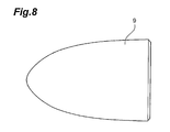
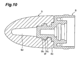
- FIGS. 8 and 9 are diagrams of the elastic body, while FIG. 10 is a vertical cross section of when the elastic body is mounted to a piston.
- the push-out applicator in this embodiment holds an application material, and allows this application material to be pushed out by suitable operation by the user.
- a lip gloss is used here as a particularly favorable example of the application material, but the application material is not limited to this, and can also be other lip care products, eye shadow, eyeliner, liquid foundation, cleansing liquid, nail enamel, nail care solution, nail polish remover, mascara, anti-aging products, hair coloring, hair care products, oral care products, massage oil, ink for marking pens and other such writing instruments, liquid medicines, and other such liquid, solid, and semisolid pastes, gels, and so forth.
- the push-out applicator 100 comprises, as its external configuration, a tip cylinder 1, the interior of which is equipped with a packing region 1x that is packed with an application material L; a base cylinder (tubular body) 2 into the front half of which is inserted the rear half of the tip cylinder 1, thereby linking the tip cylinder 1 non-rotatably and non-movably in the axial direction; and a bottomed, operating cylinder (tubular body) 3 that is linked rotatably and non-movably in the axial direction to the rear end of the base cylinder 2.
- This applicator 100 further comprises, as the mechanism for pushing out the application material L in the base cylinder 2 and the operating cylinder 3, a cylindrical shaft body 3a that is provided at the bottomed part of the operating cylinder 3 and has formed around its outer peripheral surface a rotation stop 3b extending in the axial direction; a threaded cylinder 4 that is linked non-rotatably and non-movably in the axial direction to the base cylinder 2 and has female threads 4a formed around its inner peripheral surface; a bumpy specific engagement part 3c formed in the inner peripheral direction on the inner peripheral distal end face of the operating cylinder 3; and a cylindrical click spring member 5 that is disposed between the threaded cylinder 4 and the specific engagement part 3c of the operating cylinder 3, and is non-rotatably engaged with the threaded cylinder 4.
- the click spring member 5 has a compression spring part 5b in the middle part thereof and a bump part 5a at its rear end face that is pressed against the specific engagement part 3c of the operating cylinder 3 by the compression spring part 5b and click-engages with the engagement part 3c.
- This applicator 100 further comprises a cylindrical moving body 6 into which the shaft body 3a is inserted so as to go through the click spring member 5 and the threaded cylinder 4.
- the moving body 6 has formed on its inner peripheral surface a rotation stop 6b that engages with the rotation stop 3b of the shaft body 3a, and has formed on its outer peripheral surface male threads 6a that mesh with the female threads 4a of the threaded cylinder 4 and that extend in the axial direction.
- the tip cylinder 1 holds the application material L, and discharges the application material L from the distal end part when the user places the distal end part against the application surface and operates the applicator.
- the material of which the tip cylinder 1 is made is preferably an injected molded plastic such as polyethylene terephthalate (PET) or polypropylene (PP), and is also preferably a transparent material. If a transparent material is used, then even when a cap 7 has been mounted on the tip cylinder 1, the color of the application material L can be discerned from the outside, looking through a bulging portion 1d where the tip cylinder 1 is exposed and not covered by the cap 7.
- the tip cylinder 1 is cylindrical in shape, and as shown in FIGS. 3 to 5, the outer face 1a that serves as the coating face of the distal end part is a sloped face, which is sloped with respect to the axial direction of the tip cylinder 1 to facilitate the coating of the application surface, such as the skin.
- an inner face 1b which is a sloped face that is sloped along the outer face 1a, is formed at the distal end part of the tip cylinder 1, a certain thickness away from the outer face 1a.
- a plurality of discharge openings 1c are provided for allowing the inner face 1b and the outer face 1a to communicate and for discharging the application material L packed inside the tip cylinder 1.
- the bulging portion 1d whose outside diameter is increased so as to strike the open end on the distal end side of the base cylinder 2, is provided to the outer peripheral surface of the tip cylinder 1 in the approximate middle in the axial direction.
- protrusions 1e (known as dowels) for detachably latching in the axial direction the cap 7 (see FIG. 1) that covers the part of the tip cylinder 1 ahead of the bulging portion 1d are provided at three equidistant locations in the peripheral direction, these locations being ahead of the bulging portion 1d.
- Two convex parts 1f that extend in an arc shape in the peripheral direction are provided across from each other around the outer peripheral surface of the tip cylinder 1 at locations behind the bulging portion 1d.
- the concave parts extending in an arch shape are provided at locations front the convex parts 1f, and ribs 1h that extend in the axial direction are provided at four equidistant locations in the peripheral direction, the locations being at the rear end.
- the concave parts 1g and the convex parts 1f provided next to each other in the axial direction are used to engage the tip cylinder 1 with the base cylinder 2 in the axial direction, and the ribs 1h are used to engage the tip cylinder 1 with the base cylinder 2 in the rotational direction.
- the tip cylinder 1 is inserted from its rear end side into the base cylinder 2, and as shown in FIGS. 1 and 2, the rear end face of the bulging portion 1d strikes the open end of the base cylinder 2 on its distal end side, the concave parts 1 g and the convex parts 1 f engage with an annular protrusion 2a provided around the inner peripheral surface on the distal end side of the base cylinder 2, and the ribs 1h engage with knurling 2b consisting of numerous bumps provided to the inner peripheral surface of the base cylinder 2 in the approximate center in the axial direction.
- the tip cylinder 1 is mounted on the base cylinder 2 non-rotatably and non-movably in the axial direction, and is integrated with the base cylinder 2.
- the cap 7 can also be mounted on the tip cylinder 1, as shown in FIG. 1.
- the elastic body 9 is mounted via a piston 8 at the distal end of the moving body 6.
- the piston 8 is in the form of a stepped cylinder that is closed at its distal end, and has an internal shape that accommodates the distal end part of the moving body 6.
- the front half of this piston 8 serves as a small-diameter cylindrical part 8a that is inserted into the elastic body 9, and a large-diameter cylindrical part 8b that is linked to this cylindrical part 8a via a stepped face 8c serves as a sliding part that slides watertightly through the tip cylinder 1.
- An annular concave part 8d and convex part 8e for engaging with the moving body 6 in the axial direction are provided next to each other in the axial direction around the inner peripheral surface of the piston 8.
- An annular protrusion 8f for engaging with the elastic body 9 in the axial direction is provided around the outer peripheral surface of the piston 8, at the small-diameter cylindrical part 8a thereof, and an annular protrusion 8g for ensuring a water-tight seal is provided in close contact with the inner peripheral surface of the tip cylinder 1, at the large-diameter cylindrical part 8b thereof.
- the elastic body 9 is formed from a soft elastic material that readily undergoes elastic deformation, such as silicone rubber.
- a soft elastic material that readily undergoes elastic deformation
- materials that can be selected other than silicone rubber include nitrile rubber (NBR), ethylene propylene rubber (EPR), butyl rubber (IIR), and other such thermosetting materials formed by compression molding, and polyurethane-based elastomers (TPU), polyolefin-based elastomers (TPO), polyester-based elastomers (TPEE), and other such thermoplastic materials formed by injection molding.
- this elastic body 9 is bell-shaped, tapering toward its distal end, and as shown in FIG. 9, it is equipped with a stepped concave part 9a extending from the rear end face specifically toward the distal end side, and an annular concave part 9b and convex part 9c for engaging with the annular protrusion 8f of the piston 8 in the axial direction are provided next to each other in the axial direction on the rear side of the concave part 9a.
- This elastic body 9 is inserted from its rear side over the piston 8, the rear end face thereof hits the stepped face 8c of the piston 8 as shown in FIG. 10, and the concave part 9b and convex part 9c engage with the annular protrusion 8f of the piston 8, so that the elastic body 9 is mounted to the piston 8 rotatably and non-movably in the axial direction.
- a space 9d is provided within the elastic body 9 between the piston 8 that has advanced into the concave part 9a, on the front side thereof. This space 9d serves to promote the elastic deformation of the elastic body 9.
- the piston 8 to which the elastic body 9 has been mounted is inserted from the rear side thereof over the distal end part of the moving body 6, and as shown in FIGS. 1 and 2, the concave part 8d and convex part 8e engage with an annular protrusion 6c provided to the distal end part of the moving body 6, thereby mounting the piston 8 to the moving body 6 rotatably and non-movably in the axial direction.
- the dimensions, layout, and other such settings are such that when the moving body 6 has advanced as far as it can, the elastic body 9 will be pushed on by the sloping inner face 1b of the distal end part of the tip cylinder 1.
- the elastic body 9 elastically hits the sloped inner face 1b of the distal end part of the tip cylinder 1, and elastically deforms along said sloped face. At this point, the elastic body 9 elastically deforms even more favorably due to the space 9d in the elastic body 9.
- the result of this elastic deformation of the elastic body 9 is that the application material L that would remain in the substantially hoof-shaped (sloped cylindrical) space (a space including the sloped face within the applicator distal end) and could not be pushed out with a conventional piston can be thoroughly pushed out, leaving almost none behind, so that all of it can be consumed. Accordingly, economical push-out applicator 100 can be provided with which almost none of the application material L is left unused.
- the push-out applicator 100 of this embodiment since the application material L is discharged by elastically deforming the elastic body 9 so that it conforms to the inner face 1b of the distal end part of the tip cylinder 1, even if there should be some looseness or dimensional error in the parts, the elastic deformation of the elastic body 9 will absorb this, so that the elastic body 9 can still conform to the inner face 1b, allowing the application material L to be thoroughly taken out. Also, the elastic body 9 and the inner face 1b do not have to be precisely positioned during the assembly of the applicator 100, which simplifies the assembly work. Furthermore, because there is a good seal between the elastic body 9 and the piston 8, rearward leakage of the application material L can be suppressed while the moving body 6 is pushing out.
- the present invention was described in specific terms above on the basis of an embodiment thereof, but the present invention is not limited to the above embodiment.
- the moving body 6 is configured to move forward and backward in the above embodiment, but a ratchet mechanism that permits only the rotation for forwarding the moving body 6 may be used instead of a click mechanism.
- fine bristles or the like may also be provided to the sloped outer face 1a of the tip cylinder 1.
- the push-out mechanism of the push-out applicator 100 is a rotational mechanism involving the meshing mechanisms 4a and 6a, but it is also possible to employ a knock-type push-out mechanism or the like.
- the above-mentioned male threads 6a encompass a group of protrusions laid out intermittently, or a group of protrusions laid out spirally and intermittently, having the same function as threads
- the above-mentioned female threads 4a encompass a group of protrusions laid out intermittently, or a group of protrusions laid out spirally and intermittently, having the same function as threads.
- the elastic body 9 was described as being bell-shaped, tapering toward its distal end, but the outer shape of the elastic body 9 is not limited to this, and may instead be hemispherical or the like.
- the elastic body 9 has an outer shape that does not slope along the inner face 1b of the tip cylinder 1 when there is no deformation, but rather hits the inner face 1b when the moving body 6 has advanced as far as it can, and conforms to the sloped face only upon elastic deformation. From the standpoint of pressing uniformly on the application material L, the external shape of the elastic body 9 when not deformed is in rotational symmetry around the axis of the moving body 6, such as the above-mentioned bell shape, or a hemispherical shape.
Landscapes
- Coating Apparatus (AREA)
- Containers And Packaging Bodies Having A Special Means To Remove Contents (AREA)
Abstract
Description
- The present invention relates to a push-out applicator for pushing out and applying an application material.
- Conventional moving body feed devices, which are used to push out a liquid or other such application material contained in an applicator, have been equipped with a base cylinder having on their inside a packing region packed with an application material, and an operating cylinder rotatably provided to the rear end of this base cylinder; when the base cylinder and the operating cylinder are rotated relatively, a moving body held in the base cylinder and the operating cylinder advances, causing a piston provided at the distal end of this moving body to advance, and as a result the application material is pushed out toward the distal end, passes through an opening in a discharge cap mounted at the distal end of the base cylinder, and is applied to the application surface (see
Patent Document 1 for an example of such a moving body feed device). Other such moving body feed devices have been disclosed in Patent Documents 2-7. - Patent Document 1:
Japanese Laid-Open Patent Application 2000-262324 - Patent Document 2: International Laid-Open Patent Application
WO03/017799 - Patent Document 3:
Japanese Laid-Open Utility Model Applications S60-80717 - Patent Document 4:
Japanese Laid-Open Utility Model Applications S60-80718 - Patent Document 5:
Japanese Laid-Open Patent Application H10-192049 - Patent Document 6:
Japanese Laid-Open Patent Application H10-192050 - Patent Document 7:
Japanese Laid-Open Patent Application H8-229461 - With the above devices, however, even when the moving body advances as far as it can, some of the application material remains on the inside of the distal end of the discharge cap, and ends up not being used, so improvement is needed in this respect.
- The present invention is conceived in an effort to solve this problem, and it is an object thereof to provide an economical push-out applicator with which almost none of the application material is left unused.
- The push-out applicator of the present invention is a push-out applicator having a region filled with a material to be applied, with said material being discharged through a discharge opening provided at the distal end of the applicator as a moving body disposed within the applicator advances, wherein the inner and outer faces of a distal end member having the discharge opening at the distal end of the applicator are sloped faces, and an elastic body, which hits the sloped inner face and elastically deforms along said sloped face when the moving body has advanced as far as it can, is provided to the distal end of the moving body.
- With a push-out applicator such as this, since the outer face of the distal end member having a discharge opening at the applicator distal end is a sloped face, skin or another surface to be coated can be coated favorably, and when the moving body advances as far as it can, the elastic body provided to the distal end of the moving body hits the sloped face that is the inner face of the distal end member having the discharge opening at the distal end of the applicator, and elastically deforms along said sloped face, and the application material that could not be pushed out with a conventional piston and would remain in a substantially hoof-shaped (sloped cylindrical) space (a space including the sloped face within the applicator distal end) can be completely pushed out by the elastic body, leaving almost none behind, so that all of it can be consumed.
- A specific example of a structure that effectively exhibits the above-mentioned action is one in which the applicator is equipped with tubular bodies that are mutually rotatably linked and hold the moving body, and has a anti-rotation member for the moving body and a threaded member with male and female threads that allow the movement of the moving body when these tubular bodies are rotated relatively.
- Also, if a space is provided on the inside of the elastic body, this space will facilitate elastic deformation and allow even more of the application material to be pushed out.
- Also, the above-mentioned action will be exhibited even more effectively if the elastic body is made of silicone rubber. If the external shape of the elastic body when not deformed is in rotational symmetry around the axis of the moving body, the application material can be pushed out uniformly.
- The present invention will be understood even more clearly from the following detailed description and the appended drawings. These are merely given as examples, however, and should not be construed as limiting the present invention.
- With the push-out applicator pertaining to the present invention, it is possible to provide an economical push-out applicator with which almost none of the application material is left unused.
-
- FIG. 1 is a vertical cross section of the push-out applicator pertaining to an embodiment of the present invention, and illustrates the state before the moving body has been fed out;
- FIG. 2 is a vertical cross section of when the cap has been removed from the push-out applicator pertaining to an embodiment of the present invention, and illustrates the state when the moving body has advanced as far as possible;
- FIG. 3 is a side view illustrating the tip cylinder shown in FIGS. 1 and 2;
- FIG. 4 is a bottom view of the tip cylinder shown in FIG. 3;
- FIG. 5 is a vertical cross section of the tip cylinder shown in FIG. 3 ;
- FIG. 6 is a vertically cut-away oblique view of the tip cylinder shown in FIGS. 3 to 5;
- FIG. 7 is a vertical cross section of the piston in FIGS. 1 and 2;
- FIG. 8 is a side view of the elastic body shown in FIGS. 1 and 2;
- FIG. 9 is a vertical cross section of the elastic body shown in FIG. 8; and
- FIG. 10 is a vertical cross section in which the elastic body shown in FIGS. 8 and 9 has been mounted to the piston shown in FIG. 7.
-
- 1
- tip cylinder
- 1a
- outer face of distal end of applicator
- 1b
- inner face of distal end of applicator
- 1c
- discharge opening
- 1x
- packing region
- 2
- base cylinder (tubular body)
- 3
- operating cylinder (tubular body)
- 3b
- rotation stop (anti-rotation member)
- 4a
- female threads (threaded member)
- 6
- moving body
- 6a
- male threads (threaded member)
- 6b
- rotation stop (anti-rotation member)
- 9
- elastic body
- 9d
- space for elastic body
- 100
- push-out applicator
- L
- application material
- Preferred embodiments of the push-out applicator pertaining to the present invention will now be described with reference to FIGS. 1 to 10.
- FIG. 1 is a vertical cross section of the push-out applicator pertaining to an embodiment of the present invention, and illustrates the state before the moving body has been fed out. FIG. 2 is a vertical cross section of the push-out applicator when the moving body has advanced as far as possible. FIGS. 3 to 6 are diagrams of the tip cylinder. FIG. 7 is a vertical cross section of a piston. FIGS. 8 and 9 are diagrams of the elastic body, while FIG. 10 is a vertical cross section of when the elastic body is mounted to a piston. The push-out applicator in this embodiment holds an application material, and allows this application material to be pushed out by suitable operation by the user.
- A lip gloss is used here as a particularly favorable example of the application material, but the application material is not limited to this, and can also be other lip care products, eye shadow, eyeliner, liquid foundation, cleansing liquid, nail enamel, nail care solution, nail polish remover, mascara, anti-aging products, hair coloring, hair care products, oral care products, massage oil, ink for marking pens and other such writing instruments, liquid medicines, and other such liquid, solid, and semisolid pastes, gels, and so forth.
- First, the constitution of the push-out applicator will be briefly described. As shown in FIGS. 1 and 2, the push-out
applicator 100 comprises, as its external configuration, atip cylinder 1, the interior of which is equipped with apacking region 1x that is packed with an application material L; a base cylinder (tubular body) 2 into the front half of which is inserted the rear half of thetip cylinder 1, thereby linking thetip cylinder 1 non-rotatably and non-movably in the axial direction; and a bottomed, operating cylinder (tubular body) 3 that is linked rotatably and non-movably in the axial direction to the rear end of thebase cylinder 2. Thisapplicator 100 further comprises, as the mechanism for pushing out the application material L in thebase cylinder 2 and theoperating cylinder 3, acylindrical shaft body 3a that is provided at the bottomed part of theoperating cylinder 3 and has formed around its outer peripheral surface arotation stop 3b extending in the axial direction; a threadedcylinder 4 that is linked non-rotatably and non-movably in the axial direction to thebase cylinder 2 and hasfemale threads 4a formed around its inner peripheral surface; a bumpyspecific engagement part 3c formed in the inner peripheral direction on the inner peripheral distal end face of theoperating cylinder 3; and a cylindricalclick spring member 5 that is disposed between the threadedcylinder 4 and thespecific engagement part 3c of theoperating cylinder 3, and is non-rotatably engaged with the threadedcylinder 4. Theclick spring member 5 has acompression spring part 5b in the middle part thereof and abump part 5a at its rear end face that is pressed against thespecific engagement part 3c of theoperating cylinder 3 by thecompression spring part 5b and click-engages with theengagement part 3c. Thisapplicator 100 further comprises a cylindrical movingbody 6 into which theshaft body 3a is inserted so as to go through theclick spring member 5 and the threadedcylinder 4. The movingbody 6 has formed on its inner peripheral surface arotation stop 6b that engages with the rotation stop 3b of theshaft body 3a, and has formed on its outer peripheral surfacemale threads 6a that mesh with thefemale threads 4a of the threadedcylinder 4 and that extend in the axial direction. - With this push-out
applicator 100, when the user rotates the base cylinder 2 (or thetip cylinder 1 described in detail below) relative to theoperating cylinder 3 with perceiving tactile feeling, the movingbody 6 moves straight ahead or backward under the control of a meshing mechanism (threaded part) made up of themale threads 6a of the movingbody 6 and thefemale threads 4a of the threadedcylinder 4, an anti-rotation mechanism (anti-rotation part) made up of the rotation stop 3b of theshaft body 3a and the rotation stop 6b of the movingbody 6, and a click mechanism made up of thebump part 5a and thecompression spring part 5b of theclick spring member 5 and thespecific engagement part 3c of theoperating cylinder 3. - Let us now describe the
tip cylinder 1 that constitutes the front half of the push-outapplicator 100, and theelastic body 9 mounted to the distal end of the movingbody 6. First, thetip cylinder 1 will be described in detail. - The
tip cylinder 1 holds the application material L, and discharges the application material L from the distal end part when the user places the distal end part against the application surface and operates the applicator. Accordingly, the material of which thetip cylinder 1 is made is preferably an injected molded plastic such as polyethylene terephthalate (PET) or polypropylene (PP), and is also preferably a transparent material. If a transparent material is used, then even when acap 7 has been mounted on thetip cylinder 1, the color of the application material L can be discerned from the outside, looking through a bulgingportion 1d where thetip cylinder 1 is exposed and not covered by thecap 7. - As shown in FIGS. 3 to 6, the
tip cylinder 1 is cylindrical in shape, and as shown in FIGS. 3 to 5, theouter face 1a that serves as the coating face of the distal end part is a sloped face, which is sloped with respect to the axial direction of thetip cylinder 1 to facilitate the coating of the application surface, such as the skin. As shown in FIG. 5, aninner face 1b, which is a sloped face that is sloped along theouter face 1a, is formed at the distal end part of thetip cylinder 1, a certain thickness away from theouter face 1a. Also, a plurality ofdischarge openings 1c are provided for allowing theinner face 1b and theouter face 1a to communicate and for discharging the application material L packed inside thetip cylinder 1. - Also, as shown in FIGS. 3 to 6, the bulging
portion 1d, whose outside diameter is increased so as to strike the open end on the distal end side of thebase cylinder 2, is provided to the outer peripheral surface of thetip cylinder 1 in the approximate middle in the axial direction. Also, protrusions 1e (known as dowels) for detachably latching in the axial direction the cap 7 (see FIG. 1) that covers the part of thetip cylinder 1 ahead of the bulgingportion 1d are provided at three equidistant locations in the peripheral direction, these locations being ahead of the bulgingportion 1d. Twoconvex parts 1f that extend in an arc shape in the peripheral direction are provided across from each other around the outer peripheral surface of thetip cylinder 1 at locations behind the bulgingportion 1d. The concave parts extending in an arch shape are provided at locations front theconvex parts 1f, andribs 1h that extend in the axial direction are provided at four equidistant locations in the peripheral direction, the locations being at the rear end. Theconcave parts 1g and theconvex parts 1f provided next to each other in the axial direction (see FIG. 5) are used to engage thetip cylinder 1 with thebase cylinder 2 in the axial direction, and theribs 1h are used to engage thetip cylinder 1 with thebase cylinder 2 in the rotational direction. - The
tip cylinder 1 is inserted from its rear end side into thebase cylinder 2, and as shown in FIGS. 1 and 2, the rear end face of the bulgingportion 1d strikes the open end of thebase cylinder 2 on its distal end side, theconcave parts 1 g and theconvex parts 1 f engage with anannular protrusion 2a provided around the inner peripheral surface on the distal end side of thebase cylinder 2, and theribs 1h engage withknurling 2b consisting of numerous bumps provided to the inner peripheral surface of thebase cylinder 2 in the approximate center in the axial direction. As a result, thetip cylinder 1 is mounted on thebase cylinder 2 non-rotatably and non-movably in the axial direction, and is integrated with thebase cylinder 2. Thecap 7 can also be mounted on thetip cylinder 1, as shown in FIG. 1. - The
elastic body 9 is mounted via apiston 8 at the distal end of the movingbody 6. As shown in FIG. 7, thepiston 8 is in the form of a stepped cylinder that is closed at its distal end, and has an internal shape that accommodates the distal end part of the movingbody 6. The front half of thispiston 8 serves as a small-diametercylindrical part 8a that is inserted into theelastic body 9, and a large-diametercylindrical part 8b that is linked to thiscylindrical part 8a via a steppedface 8c serves as a sliding part that slides watertightly through thetip cylinder 1. - An annular
concave part 8d andconvex part 8e for engaging with the movingbody 6 in the axial direction are provided next to each other in the axial direction around the inner peripheral surface of thepiston 8. Anannular protrusion 8f for engaging with theelastic body 9 in the axial direction is provided around the outer peripheral surface of thepiston 8, at the small-diametercylindrical part 8a thereof, and anannular protrusion 8g for ensuring a water-tight seal is provided in close contact with the inner peripheral surface of thetip cylinder 1, at the large-diametercylindrical part 8b thereof. - The
elastic body 9 is formed from a soft elastic material that readily undergoes elastic deformation, such as silicone rubber. Materials that can be selected other than silicone rubber include nitrile rubber (NBR), ethylene propylene rubber (EPR), butyl rubber (IIR), and other such thermosetting materials formed by compression molding, and polyurethane-based elastomers (TPU), polyolefin-based elastomers (TPO), polyester-based elastomers (TPEE), and other such thermoplastic materials formed by injection molding. - As shown in FIGS. 8 and 9, this
elastic body 9 is bell-shaped, tapering toward its distal end, and as shown in FIG. 9, it is equipped with a steppedconcave part 9a extending from the rear end face specifically toward the distal end side, and an annularconcave part 9b andconvex part 9c for engaging with theannular protrusion 8f of thepiston 8 in the axial direction are provided next to each other in the axial direction on the rear side of theconcave part 9a. - This
elastic body 9 is inserted from its rear side over thepiston 8, the rear end face thereof hits the steppedface 8c of thepiston 8 as shown in FIG. 10, and theconcave part 9b andconvex part 9c engage with theannular protrusion 8f of thepiston 8, so that theelastic body 9 is mounted to thepiston 8 rotatably and non-movably in the axial direction. In this state, aspace 9d is provided within theelastic body 9 between thepiston 8 that has advanced into theconcave part 9a, on the front side thereof. Thisspace 9d serves to promote the elastic deformation of theelastic body 9. - The
piston 8 to which theelastic body 9 has been mounted is inserted from the rear side thereof over the distal end part of the movingbody 6, and as shown in FIGS. 1 and 2, theconcave part 8d andconvex part 8e engage with anannular protrusion 6c provided to the distal end part of the movingbody 6, thereby mounting thepiston 8 to the movingbody 6 rotatably and non-movably in the axial direction. - With the push-out
applicator 100 configured in this way, the dimensions, layout, and other such settings are such that when the movingbody 6 has advanced as far as it can, theelastic body 9 will be pushed on by the slopinginner face 1b of the distal end part of thetip cylinder 1. - With this push-out
applicator 100, as discussed above, when the user relatively rotates thebase cylinder 2 or thetip cylinder 1 and theoperating cylinder 3 in the direction of advance of the movingbody 6 with perceiving tactile feeling, the movingbody 6 moves forward, the application material L packed in thetip cylinder 1 is pushed out forward by theelastic body 9, discharged from thedischarge openings 1c, and applied. - As shown in FIG. 2, particularly with the push-out
applicator 100 of this embodiment, when the relative rotation provided by the user advances the movingbody 6 as far as it can go, theelastic body 9 elastically hits the slopedinner face 1b of the distal end part of thetip cylinder 1, and elastically deforms along said sloped face. At this point, theelastic body 9 elastically deforms even more favorably due to thespace 9d in theelastic body 9. The result of this elastic deformation of theelastic body 9 is that the application material L that would remain in the substantially hoof-shaped (sloped cylindrical) space (a space including the sloped face within the applicator distal end) and could not be pushed out with a conventional piston can be thoroughly pushed out, leaving almost none behind, so that all of it can be consumed. Accordingly, economical push-outapplicator 100 can be provided with which almost none of the application material L is left unused. - Also, with the push-out
applicator 100 of this embodiment, since the application material L is discharged by elastically deforming theelastic body 9 so that it conforms to theinner face 1b of the distal end part of thetip cylinder 1, even if there should be some looseness or dimensional error in the parts, the elastic deformation of theelastic body 9 will absorb this, so that theelastic body 9 can still conform to theinner face 1b, allowing the application material L to be thoroughly taken out. Also, theelastic body 9 and theinner face 1b do not have to be precisely positioned during the assembly of theapplicator 100, which simplifies the assembly work. Furthermore, because there is a good seal between theelastic body 9 and thepiston 8, rearward leakage of the application material L can be suppressed while the movingbody 6 is pushing out. - The present invention was described in specific terms above on the basis of an embodiment thereof, but the present invention is not limited to the above embodiment. For example, the moving
body 6 is configured to move forward and backward in the above embodiment, but a ratchet mechanism that permits only the rotation for forwarding the movingbody 6 may be used instead of a click mechanism. - Naturally, fine bristles or the like may also be provided to the sloped
outer face 1a of thetip cylinder 1. - Also, it is particularly favorable in the above embodiment if the push-out mechanism of the push-out
applicator 100 is a rotational mechanism involving the meshingmechanisms - Furthermore, the above-mentioned
male threads 6a encompass a group of protrusions laid out intermittently, or a group of protrusions laid out spirally and intermittently, having the same function as threads, and the above-mentionedfemale threads 4a encompass a group of protrusions laid out intermittently, or a group of protrusions laid out spirally and intermittently, having the same function as threads. - Also, the
elastic body 9 was described as being bell-shaped, tapering toward its distal end, but the outer shape of theelastic body 9 is not limited to this, and may instead be hemispherical or the like. However, theelastic body 9 has an outer shape that does not slope along theinner face 1b of thetip cylinder 1 when there is no deformation, but rather hits theinner face 1b when the movingbody 6 has advanced as far as it can, and conforms to the sloped face only upon elastic deformation. From the standpoint of pressing uniformly on the application material L, the external shape of theelastic body 9 when not deformed is in rotational symmetry around the axis of the movingbody 6, such as the above-mentioned bell shape, or a hemispherical shape.
Claims (5)
- A push-out applicator, having a region filled with a material to be applied, with said material being discharged through a discharge opening provided at the distal end of the applicator as a moving body disposed within the applicator advances,
wherein the inner and outer faces of a distal end part having the discharge opening at the distal end of the applicator are sloped faces, and
an elastic body, which hits the sloped inner face and elastically deforms along said sloped face when the moving body has advanced as far as the moving body can, is provided to the distal end of the moving body. - The push-out applicator according to Claim 1, wherein the applicator comprises tubular bodies that are mutually rotatably linked and hold the moving body, and has an anti-rotation part for the moving body and a threaded part with male and female threads that allow the movement of the moving body when the tubular bodies are rotated relatively.
- The push-out applicator according to Claim 1 or Claim 2, wherein a space is provided on the inside of the elastic body.
- The push-out applicator according to any one of Claims 1 to 3, wherein the elastic body is made of silicone rubber.
- The push-out applicator according to any one of Claims 1 to 4, wherein the external shape of the elastic body when not deformed is in rotational symmetry around the axis of the moving body.
Applications Claiming Priority (2)
| Application Number | Priority Date | Filing Date | Title |
|---|---|---|---|
| JP2004326938 | 2004-11-10 | ||
| PCT/JP2005/016429 WO2006051646A1 (en) | 2004-11-10 | 2005-09-07 | Filler extruding container for coating |
Publications (3)
| Publication Number | Publication Date |
|---|---|
| EP1829460A1 true EP1829460A1 (en) | 2007-09-05 |
| EP1829460A4 EP1829460A4 (en) | 2009-05-13 |
| EP1829460B1 EP1829460B1 (en) | 2010-11-10 |
Family
ID=36336329
Family Applications (1)
| Application Number | Title | Priority Date | Filing Date |
|---|---|---|---|
| EP05782253A Expired - Lifetime EP1829460B1 (en) | 2004-11-10 | 2005-09-07 | Applicator with a piston to dispense content |
Country Status (5)
| Country | Link |
|---|---|
| US (1) | US7857538B2 (en) |
| EP (1) | EP1829460B1 (en) |
| CN (1) | CN100525673C (en) |
| DE (1) | DE602005024712D1 (en) |
| WO (1) | WO2006051646A1 (en) |
Cited By (2)
| Publication number | Priority date | Publication date | Assignee | Title |
|---|---|---|---|---|
| FR2923999A1 (en) * | 2007-11-26 | 2009-05-29 | Tokiwa Corp | Cosmetic material e.g. lipstick, dispensing container, has movable body moved back, so that aspiration force is applied based on rear movement of extrusion portion, and material is withdrawn in filling element |
| CN102049947A (en) * | 2009-11-02 | 2011-05-11 | 王华伍 | Metering correction pen |
Families Citing this family (11)
| Publication number | Priority date | Publication date | Assignee | Title |
|---|---|---|---|---|
| JP4387365B2 (en) * | 2006-03-07 | 2009-12-16 | 三菱鉛筆株式会社 | Liquid applicator |
| JP4355753B1 (en) * | 2008-10-29 | 2009-11-04 | 株式会社トキワ | Coating material extrusion container |
| CN101897512B (en) * | 2009-05-31 | 2012-07-04 | 苏州洽兴塑胶有限公司 | Inflatable lash brush |
| US9044078B2 (en) * | 2010-09-24 | 2015-06-02 | Tokiwa Corporation | Cosmetic material application container |
| CN102294913A (en) * | 2011-06-22 | 2011-12-28 | 邹乐华 | Pen capable of automatically absorbing ink |
| US9474348B2 (en) * | 2013-07-29 | 2016-10-25 | Tokiwa Corporation | Applying material extruding container |
| CN104783479B (en) * | 2014-01-21 | 2017-09-22 | 株式会社常盘 | coating material extruding container |
| JP6281068B2 (en) * | 2015-07-01 | 2018-02-21 | 株式会社トキワ | Stick-shaped cosmetic supply container |
| KR101661240B1 (en) * | 2016-03-15 | 2016-09-30 | (주)하배런메디엔뷰티 | Galvanic beauty treatment device |
| JP2017189466A (en) * | 2016-04-14 | 2017-10-19 | 株式会社トキワ | Bar-like cosmetic delivering container |
| CN106175034B (en) * | 2016-09-09 | 2020-01-07 | 深圳市多鑫源科技有限公司 | Silica gel eye shadow stick |
Family Cites Families (19)
| Publication number | Priority date | Publication date | Assignee | Title |
|---|---|---|---|---|
| GB999506A (en) * | 1960-11-02 | 1965-07-28 | Engis Ltd | Improvements in syringes for dispensing paste or the like |
| US4323157A (en) * | 1980-10-17 | 1982-04-06 | Eyelet Specialty Co., Inc. | Bottom-fillable lipstick or the like container |
| JPS6080717A (en) | 1983-10-07 | 1985-05-08 | Yokogawa Hokushin Electric Corp | Recorder |
| JPS6080718A (en) | 1983-10-07 | 1985-05-08 | Yokogawa Hokushin Electric Corp | Depressor bar type recorder |
| CN1066621C (en) * | 1994-07-08 | 2001-06-06 | 株式会社希丹 | A cosmetic container |
| FR2727608B1 (en) | 1994-12-06 | 1997-01-10 | Oreal | DISPENSER FOR A LIQUID CONSISTENCY PRODUCT WITH PASTE |
| ES2220921T3 (en) * | 1994-12-06 | 2004-12-16 | L'oreal | DISTRIBUTOR FOR A LIQUID TO PASTOSE CONSISTENCY PRODUCT EQUIPPED WITH AN APPLICATION TUBULAR ELEMENT. |
| GB9521992D0 (en) * | 1995-10-27 | 1996-01-03 | Unilever Plc | Dispensing package |
| JPH09206377A (en) * | 1996-01-31 | 1997-08-12 | Daikyo Seiko:Kk | Syringe stopper |
| JPH10192049A (en) | 1996-12-27 | 1998-07-28 | Kao Corp | Pen type lip cosmetics |
| JPH10192050A (en) | 1996-12-27 | 1998-07-28 | Kao Corp | Pen type lip cosmetics |
| CN2297904Y (en) * | 1997-05-12 | 1998-11-25 | 德奎实业(上海)有限公司 | Shell structure of lipstick |
| US6186686B1 (en) * | 1997-07-02 | 2001-02-13 | Henlopen Manufacturing Co., Inc. | Applicator for liquid material |
| JP3660948B2 (en) | 1999-03-16 | 2005-06-15 | 株式会社トキワ | Screw rod feeding device and piston-type extrusion container using this device |
| US6607323B2 (en) | 2000-02-29 | 2003-08-19 | Diane C. Breidenbach | Lip product applicator |
| US6488427B1 (en) * | 2000-02-29 | 2002-12-03 | Diane C. Breidenbach | Cosmetic applicator |
| JP3735100B2 (en) | 2002-07-09 | 2006-01-11 | 株式会社トキワ | Mobile body feeding device |
| CN2636698Y (en) * | 2003-07-07 | 2004-09-01 | 蔡懿丽 | Cosmetics container extrusion device |
| JP3796258B2 (en) * | 2004-11-10 | 2006-07-12 | 株式会社トキワ | Liquid filling extrusion container |
-
2005
- 2005-09-07 EP EP05782253A patent/EP1829460B1/en not_active Expired - Lifetime
- 2005-09-07 CN CNB2005800158743A patent/CN100525673C/en not_active Expired - Lifetime
- 2005-09-07 US US11/664,643 patent/US7857538B2/en active Active
- 2005-09-07 DE DE602005024712T patent/DE602005024712D1/en not_active Expired - Lifetime
- 2005-09-07 WO PCT/JP2005/016429 patent/WO2006051646A1/en not_active Ceased
Cited By (2)
| Publication number | Priority date | Publication date | Assignee | Title |
|---|---|---|---|---|
| FR2923999A1 (en) * | 2007-11-26 | 2009-05-29 | Tokiwa Corp | Cosmetic material e.g. lipstick, dispensing container, has movable body moved back, so that aspiration force is applied based on rear movement of extrusion portion, and material is withdrawn in filling element |
| CN102049947A (en) * | 2009-11-02 | 2011-05-11 | 王华伍 | Metering correction pen |
Also Published As
| Publication number | Publication date |
|---|---|
| CN100525673C (en) | 2009-08-12 |
| US20080107472A1 (en) | 2008-05-08 |
| EP1829460A4 (en) | 2009-05-13 |
| US7857538B2 (en) | 2010-12-28 |
| WO2006051646A1 (en) | 2006-05-18 |
| CN1953680A (en) | 2007-04-25 |
| EP1829460B1 (en) | 2010-11-10 |
| DE602005024712D1 (en) | 2010-12-23 |
Similar Documents
| Publication | Publication Date | Title |
|---|---|---|
| KR100821447B1 (en) | Filling Extrusion Container for Coating | |
| EP1829460B1 (en) | Applicator with a piston to dispense content | |
| US8590754B2 (en) | Filling material extruding container | |
| KR101505314B1 (en) | Cosmetic material application container | |
| CN102415677B (en) | Cosmetic applying container | |
| KR200495388Y1 (en) | Multicolor Press-On Makeup Pen | |
| US7147396B2 (en) | Applying filler extruding container | |
| US8104984B2 (en) | Filled material extruding container | |
| US6957753B2 (en) | Movable body feeding apparatus | |
| CN110996714A (en) | Device for dispensing and applying cosmetic or care products | |
| JP2009039173A (en) | Coating material extrusion container | |
| JP4740173B2 (en) | Coating material extrusion container | |
| JP4607746B2 (en) | Contents extrusion container | |
| JP4627433B2 (en) | Mobile feeding container | |
| JP3991059B2 (en) | Filler extrusion container for coating | |
| JP3769585B1 (en) | Filler extrusion container for coating | |
| KR200350245Y1 (en) | A push button type cosmetic vessel containing a gel cosmetic material | |
| JP4028880B2 (en) | Filler extrusion container for coating | |
| JP5457389B2 (en) | Coating material extrusion container | |
| JP4579653B2 (en) | Filler extrusion container for coating | |
| JP7329234B2 (en) | Application material extrusion container | |
| KR20130002294U (en) | Dosed discharging vessels of contents |
Legal Events
| Date | Code | Title | Description |
|---|---|---|---|
| PUAI | Public reference made under article 153(3) epc to a published international application that has entered the european phase |
Free format text: ORIGINAL CODE: 0009012 |
|
| 17P | Request for examination filed |
Effective date: 20070120 |
|
| AK | Designated contracting states |
Kind code of ref document: A1 Designated state(s): DE ES FR GB IT |
|
| DAX | Request for extension of the european patent (deleted) | ||
| RBV | Designated contracting states (corrected) |
Designated state(s): DE ES FR GB IT |
|
| A4 | Supplementary search report drawn up and despatched |
Effective date: 20090414 |
|
| 17Q | First examination report despatched |
Effective date: 20090703 |
|
| GRAP | Despatch of communication of intention to grant a patent |
Free format text: ORIGINAL CODE: EPIDOSNIGR1 |
|
| RTI1 | Title (correction) |
Free format text: APPLICATOR WITH A PISTON TO DISPENSE CONTENT |
|
| GRAS | Grant fee paid |
Free format text: ORIGINAL CODE: EPIDOSNIGR3 |
|
| GRAA | (expected) grant |
Free format text: ORIGINAL CODE: 0009210 |
|
| AK | Designated contracting states |
Kind code of ref document: B1 Designated state(s): DE ES FR GB IT |
|
| REG | Reference to a national code |
Ref country code: GB Ref legal event code: FG4D |
|
| REF | Corresponds to: |
Ref document number: 602005024712 Country of ref document: DE Date of ref document: 20101223 Kind code of ref document: P |
|
| PG25 | Lapsed in a contracting state [announced via postgrant information from national office to epo] |
Ref country code: ES Free format text: LAPSE BECAUSE OF FAILURE TO SUBMIT A TRANSLATION OF THE DESCRIPTION OR TO PAY THE FEE WITHIN THE PRESCRIBED TIME-LIMIT Effective date: 20110221 |
|
| PLBE | No opposition filed within time limit |
Free format text: ORIGINAL CODE: 0009261 |
|
| STAA | Information on the status of an ep patent application or granted ep patent |
Free format text: STATUS: NO OPPOSITION FILED WITHIN TIME LIMIT |
|
| 26N | No opposition filed |
Effective date: 20110811 |
|
| REG | Reference to a national code |
Ref country code: DE Ref legal event code: R097 Ref document number: 602005024712 Country of ref document: DE Effective date: 20110811 |
|
| PG25 | Lapsed in a contracting state [announced via postgrant information from national office to epo] |
Ref country code: IT Free format text: LAPSE BECAUSE OF FAILURE TO SUBMIT A TRANSLATION OF THE DESCRIPTION OR TO PAY THE FEE WITHIN THE PRESCRIBED TIME-LIMIT Effective date: 20101110 |
|
| REG | Reference to a national code |
Ref country code: FR Ref legal event code: PLFP Year of fee payment: 12 |
|
| REG | Reference to a national code |
Ref country code: FR Ref legal event code: PLFP Year of fee payment: 13 |
|
| REG | Reference to a national code |
Ref country code: FR Ref legal event code: PLFP Year of fee payment: 14 |
|
| PGFP | Annual fee paid to national office [announced via postgrant information from national office to epo] |
Ref country code: DE Payment date: 20190731 Year of fee payment: 15 |
|
| PGFP | Annual fee paid to national office [announced via postgrant information from national office to epo] |
Ref country code: GB Payment date: 20190731 Year of fee payment: 15 |
|
| REG | Reference to a national code |
Ref country code: DE Ref legal event code: R119 Ref document number: 602005024712 Country of ref document: DE |
|
| GBPC | Gb: european patent ceased through non-payment of renewal fee |
Effective date: 20200907 |
|
| PG25 | Lapsed in a contracting state [announced via postgrant information from national office to epo] |
Ref country code: DE Free format text: LAPSE BECAUSE OF NON-PAYMENT OF DUE FEES Effective date: 20210401 |
|
| PG25 | Lapsed in a contracting state [announced via postgrant information from national office to epo] |
Ref country code: GB Free format text: LAPSE BECAUSE OF NON-PAYMENT OF DUE FEES Effective date: 20200907 |
|
| P01 | Opt-out of the competence of the unified patent court (upc) registered |
Effective date: 20230529 |
|
| PGFP | Annual fee paid to national office [announced via postgrant information from national office to epo] |
Ref country code: FR Payment date: 20240926 Year of fee payment: 20 |