EP1828847B1 - Three-dimensional structures for an ink jet printhead and relevant manufacturing process - Google Patents
Three-dimensional structures for an ink jet printhead and relevant manufacturing process Download PDFInfo
- Publication number
- EP1828847B1 EP1828847B1 EP04806883A EP04806883A EP1828847B1 EP 1828847 B1 EP1828847 B1 EP 1828847B1 EP 04806883 A EP04806883 A EP 04806883A EP 04806883 A EP04806883 A EP 04806883A EP 1828847 B1 EP1828847 B1 EP 1828847B1
- Authority
- EP
- European Patent Office
- Prior art keywords
- process according
- polymerization inhibitor
- radiation
- polymerization
- areas
- Prior art date
- Legal status (The legal status is an assumption and is not a legal conclusion. Google has not performed a legal analysis and makes no representation as to the accuracy of the status listed.)
- Expired - Lifetime
Links
Images


Classifications
-
- B—PERFORMING OPERATIONS; TRANSPORTING
- B41—PRINTING; LINING MACHINES; TYPEWRITERS; STAMPS
- B41J—TYPEWRITERS; SELECTIVE PRINTING MECHANISMS, i.e. MECHANISMS PRINTING OTHERWISE THAN FROM A FORME; CORRECTION OF TYPOGRAPHICAL ERRORS
- B41J2/00—Typewriters or selective printing mechanisms characterised by the printing or marking process for which they are designed
- B41J2/005—Typewriters or selective printing mechanisms characterised by the printing or marking process for which they are designed characterised by bringing liquid or particles selectively into contact with a printing material
- B41J2/01—Ink jet
- B41J2/135—Nozzles
- B41J2/16—Production of nozzles
- B41J2/1601—Production of bubble jet print heads
- B41J2/1603—Production of bubble jet print heads of the front shooter type
-
- B—PERFORMING OPERATIONS; TRANSPORTING
- B41—PRINTING; LINING MACHINES; TYPEWRITERS; STAMPS
- B41J—TYPEWRITERS; SELECTIVE PRINTING MECHANISMS, i.e. MECHANISMS PRINTING OTHERWISE THAN FROM A FORME; CORRECTION OF TYPOGRAPHICAL ERRORS
- B41J2/00—Typewriters or selective printing mechanisms characterised by the printing or marking process for which they are designed
- B41J2/005—Typewriters or selective printing mechanisms characterised by the printing or marking process for which they are designed characterised by bringing liquid or particles selectively into contact with a printing material
- B41J2/01—Ink jet
- B41J2/135—Nozzles
- B41J2/16—Production of nozzles
- B41J2/1621—Manufacturing processes
- B41J2/1626—Manufacturing processes etching
-
- B—PERFORMING OPERATIONS; TRANSPORTING
- B41—PRINTING; LINING MACHINES; TYPEWRITERS; STAMPS
- B41J—TYPEWRITERS; SELECTIVE PRINTING MECHANISMS, i.e. MECHANISMS PRINTING OTHERWISE THAN FROM A FORME; CORRECTION OF TYPOGRAPHICAL ERRORS
- B41J2/00—Typewriters or selective printing mechanisms characterised by the printing or marking process for which they are designed
- B41J2/005—Typewriters or selective printing mechanisms characterised by the printing or marking process for which they are designed characterised by bringing liquid or particles selectively into contact with a printing material
- B41J2/01—Ink jet
- B41J2/135—Nozzles
- B41J2/16—Production of nozzles
- B41J2/1621—Manufacturing processes
- B41J2/1631—Manufacturing processes photolithography
-
- B—PERFORMING OPERATIONS; TRANSPORTING
- B41—PRINTING; LINING MACHINES; TYPEWRITERS; STAMPS
- B41J—TYPEWRITERS; SELECTIVE PRINTING MECHANISMS, i.e. MECHANISMS PRINTING OTHERWISE THAN FROM A FORME; CORRECTION OF TYPOGRAPHICAL ERRORS
- B41J2/00—Typewriters or selective printing mechanisms characterised by the printing or marking process for which they are designed
- B41J2/005—Typewriters or selective printing mechanisms characterised by the printing or marking process for which they are designed characterised by bringing liquid or particles selectively into contact with a printing material
- B41J2/01—Ink jet
- B41J2/135—Nozzles
- B41J2/16—Production of nozzles
- B41J2/1621—Manufacturing processes
- B41J2/164—Manufacturing processes thin film formation
- B41J2/1645—Manufacturing processes thin film formation thin film formation by spincoating
-
- G—PHYSICS
- G03—PHOTOGRAPHY; CINEMATOGRAPHY; ANALOGOUS TECHNIQUES USING WAVES OTHER THAN OPTICAL WAVES; ELECTROGRAPHY; HOLOGRAPHY
- G03F—PHOTOMECHANICAL PRODUCTION OF TEXTURED OR PATTERNED SURFACES, e.g. FOR PRINTING, FOR PROCESSING OF SEMICONDUCTOR DEVICES; MATERIALS THEREFOR; ORIGINALS THEREFOR; APPARATUS SPECIALLY ADAPTED THEREFOR
- G03F7/00—Photomechanical, e.g. photolithographic, production of textured or patterned surfaces, e.g. printing surfaces; Materials therefor, e.g. comprising photoresists; Apparatus specially adapted therefor
- G03F7/004—Photosensitive materials
- G03F7/038—Macromolecular compounds which are rendered insoluble or differentially wettable
-
- G—PHYSICS
- G03—PHOTOGRAPHY; CINEMATOGRAPHY; ANALOGOUS TECHNIQUES USING WAVES OTHER THAN OPTICAL WAVES; ELECTROGRAPHY; HOLOGRAPHY
- G03F—PHOTOMECHANICAL PRODUCTION OF TEXTURED OR PATTERNED SURFACES, e.g. FOR PRINTING, FOR PROCESSING OF SEMICONDUCTOR DEVICES; MATERIALS THEREFOR; ORIGINALS THEREFOR; APPARATUS SPECIALLY ADAPTED THEREFOR
- G03F7/00—Photomechanical, e.g. photolithographic, production of textured or patterned surfaces, e.g. printing surfaces; Materials therefor, e.g. comprising photoresists; Apparatus specially adapted therefor
- G03F7/004—Photosensitive materials
- G03F7/09—Photosensitive materials characterised by structural details, e.g. supports, auxiliary layers
- G03F7/091—Photosensitive materials characterised by structural details, e.g. supports, auxiliary layers characterised by antireflection means or light filtering or absorbing means, e.g. anti-halation, contrast enhancement
Definitions
- This invention relates to three-dimensional structures, used in an ink jet printhead and the relevant manufacturing process.
- the printhead that this invention relates to is of the type in which ink droplets are ejected through an ejection duct, or nozzle, communicating with a vaporisation chamber, in which a bubble of vapour is produced.
- Ink jet printheads are known in the art, in which the energy for expelling the drops of ink is obtained from the vaporisation of a small volume of ink contained in the vaporisation chambers, which is expelled through the nozzles communicating with these chambers.
- Vaporisation of the ink is caused by a resistor placed within the chambers and suitably energized by means of electronic microcircuits.
- the ink is supplied through a feeding duct which is in communication with both the chamber, and also with a slot, made in the thickness of a silicon die.
- microhydraulics is understood to mean as a whole the nozzles, the vaporisation chambers and the ink feeding ducts connected to them.
- microelectronics is understood to mean as a whole the active and passive electronic components, produced by means of photolithography on the silicon die.
- Ink jet heads have their microhydraulics made in a single layer of material, called the structural layer. This can be done by making templates of the hydraulic microcircuit with a sacrificial layer, depositing a solution of photosensitive material on it, polymerizing it and finally removing the sacrificial layer.
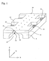
- FIG. 1 The structure of a monolithic head is illustrated in Figure 1 by means of an axonometric projection sectioned parallel to the x-z axis; depicted in the figure are:
- microelectronics are built on the upper face of the silicon die 4, and are not visible in fig. 1 as they are hidden by the structural layer 25.
- the pads 23 have the function of electrically connecting the microelectronics with the circuits external to the head, through contact with special external conductors called "fingers".
- the fingers and the microelectronics are not depicted in any figures as they are not essential for an understanding of the invention.
- Ink jet heads having for example 300 nozzles, a definition for example of 600 dots per inch (dpi), and suitable for emitting drops of volume 5 pl for example, have chambers with dimensions in the order of tens of ⁇ m (for instance, they have side of about 20 ⁇ m and thickness about 10 ⁇ m), with tolerances in the order of a ⁇ m.
- dpi dots per inch
- the apertures have dimensions in the order of tens or hundreds of ⁇ m (for instance, they have side of about 100 ⁇ m with tolerances in the order of a ⁇ m) and are typically of the same height as the chambers.
- microelectronics underneath are, on the other hand, made from elements whose dimensions are in the order of a ⁇ m, meaning therefore that they are typically smaller than the elements of the microhydraulics by two orders of magnitude.
- layers of polymerizable materials are used for the purpose of selectively protecting certain portions of the die being worked on, intended to be removed later.
- These layers are substantially different from the structural layer that makes up the microhydraulics, in particular they typically have a thickness in the order of a ⁇ m or less and, as they are intended to be removed in later work phases, are made of materials of low mechanical characteristics and adhesion to the adjacent layers.
- the structural layer 25 displays excellent chemical inertness in respect of the ink, for instance even when the ink, for reasons linked to the stability of the raw materials used to manufacture it, has high alkalinity values.
- the structural layer should conveniently also have a sufficient mechanical resistance and optimal adhesion to the substrate, even if remaining constantly in contact with the ink.
- the US patent no. 6,123,863 describes a process for the production of an ink jet printhead comprising the phases of producing, in a sacrificial layer of positive resist deposited on the silicon substrate, the templates of the hydraulic microcircuits, covering the sacrificial layer with a structural layer made, inter alia, from a preparation based on photopolymerizable epoxy resin cycloaliphatic (EHPE 3150 Daicel), and after polymerization of the structural layer, removing the sacrificial layer with one or more solvents belonging to the family of aliphatic esters of lactic acid chosen from methyl lactate, ethyl lactate and butyl lactate.
- EHPE 3150 Daicel photopolymerizable epoxy resin cycloaliphatic
- US patent no. 6,753,128 proposes a photosensitive solution made up of a photopolymer, a photoinitiator and a basic additive suitable for neutralizing the acid species that have migrated, or spread into unexposed areas.
- the basic additive is made up of basic compounds with a fluorendiamine and naftalendiamine structure, with high degree of basicity, as the coefficient of acidity of the conjugate acid (pKa) is between 12 and 16.
- the basic additive is present in the photopolymerizable solution in an amount that is between 0.5% and 20% in weight of the photoinitiator.
- the results give a value for LER (Line Edge Roughness) of 9-13 nm, in comparison with a LER value of 10-20 nm obtained in the absence of the proposed additive.
- US patent no. 5,683,856 describes a process intended to improve the definition of ultrafine structures made in a polymerized layer, by eliminating the imperfections caused by a migration of acid species into areas not exposed to radiation, or by basic impurities present in the atmosphere, which alter the concentration of the acid species on the surface of the photopolymer. It proposes a photosensitive composition with positive action comprising a photoinitiator, a component inhibiting dissolution of the polymer and a basic species made up of polymers containing nitrogen. The results refer to a resolution, in the structures made in this way, of between 260 and 480 nm, indicated as difficult to obtain without the additive proposed.
- US patent no. 5,981,139 refers to the production of structures in a photopolymer, comprising a photosensitive compound of the chemical amplification type, containing a generator of photosensitive acid species; when this photopolymer is used in the presence of basic environmental contaminants, such as for instance, ammoniacal gases, or in contact with an isolating layer of silicon nitride, impregnated with ammonia or water, or again in contact with layers of a phosphorous and boron based glass, deactivation of part of the acid species may be observed. As a result, irregularly-shaped structures are formed, for instance with rounded corners, or with polymer residues.
- the European patent application EP 1 253 138 relates to the problem of eliminating, as in those quoted previously, the geometric deformations of three-dimensional ultrafine structures having resolution of 200 nm or less, caused by the presence of basic contaminant components present in the air, which neutralize the acid species of the photopolymer; for this purpose, the above-mentioned European patent application EP 1 253 138 proposes using, as additives to the chemical amplification photopolymer, basic compounds consisting of tertiary amines containing an ester group.
- the structures of the microhydraulics relative to this invention have typical dimensions of tens or hundreds of ⁇ m, with tolerances in the order of the ⁇ m. These are not therefore affected by the problems tackled by the above-mentioned patents, as the tolerances are wider than the defects that these patents propose eliminating.
- the photo depicts a cavity 20, suitable for constituting, for instance, an aperture 12, and having dimensions of several hundreds of ⁇ m, as shown from the dimensional scale included in the picture.
- a metallic part 36 On the bottom wall 15 of the cavity is a metallic part 36 also having dimensions in the order of hundreds of ⁇ m, suitable for constituting, for instance, a pad or an electric conductor.
- the residues 40 have dimensions between, for instance, a few tens and a few hundreds of a ⁇ m, they therefore concern a large part of the area of the cavity 20 and of the metallic part 36, and generate drawbacks in the subsequent head assembly processes, drastically reducing the yields and increasing the production cost: if for example, the metallic part 36 were to be a pad, the residues 40 could prevent an effective electrical contact from being established with the relative finger, meaning that the head in question would be rejected.
- the inventors believe that the phenomenon of unwanted polymerization observed in the areas not exposed to radiation is due to the generation of acid species due to reflection of the radiation on reflecting portions of the bottom wall of the tridimensional structures in the areas underneath the mask, and not to migration of the acid species generated during the exposure.
- This unwanted polymerization extends over tens or even hundreds of ⁇ m, as already observed in the photo of Fig. 2 .
- the problem of diffusion of the acid species in the technology of ultrafine integrated circuit structures concerns dimensions of the order of a tens of nanometers, i.e. about two orders of magnitude less than the desired tolerances in microhydraulics of the heads, and from three to four orders of magnitude less than the dimensions of the residues observed by the inventors.
- acid species is taken to mean hydrogen ions or groups likely to promote the polymerization of cationic polymerization monomers or oligomers.
- this phenomenon of undesired polymerization was caused by the reflection of the radiation striking surfaces of any shape and extent, and typically takes place when the surfaces reflect a percentage of incident radiation between 50 and 95%, and more specifically at least equal to 70%.
- the applicant has therefore noted that the problem of the presence of defects in the walls of the structural layers in heads for ink jet printing, was due to reflectivity of the substrate on which said structural layer was made, and which could therefore be resolved by controlling the polymerization in the areas protected by masking, in particular through the use of a controlled quantity of the polymerization inhibitor in said structural layer, said quantity being insufficient to prevent polymerization in the areas subjected to direct radiation, but sufficient to ward off polymerization in the areas exposed to reflection.
- the method of producing three dimensional structures for an ink jet printhead makes use of a polymeric structural layer obtained from a photosensitive mix containing at least one monomer or one epoxy oligomer, a photoinitiator capable of generating Lewis acids when struck by UV radiation, and a basic polymerization inhibitor compound, mixed in a measure at least sufficient to neutralize the acid species unduly generated in the areas not exposed to direct radiation, on account of reflection of the radiation on reflecting portions of the support surface.
- the inhibitor compound must be mixed in sufficiently low measure to be fully consumed in the areas exposed to direct radiation, and thus allow polymerization of the structural layer in these areas.
- this invention relates to a photolithographic process for making three dimensional structures in a structural layer in photopolymer for an ink jet printhead.
- the three dimensional structures are made on a substrate having a bottom wall at least in part reflecting, and comprise at least one side wall adjacent to said bottom wall.
- the process comprises the operations of:
- the polymerization inhibitor is chosen from: N,N-dimethylaniline; pyridine; hydroxylamine; 2,6-dimethylpyridine; 4-dimethylaminopyridine; imidazole; morpholine; hydrazine; piperidine; triisopropanolamine; methylamine; ethylamine; diethylamine; triethylamine.
- the polymerization inhibitor comprises tris-(2-hydroxy-1-propyl)amine, or piperidine, or 4-dimethylaminopyridine.
- the polymerization inhibitor has a coefficient of acidity of the conjugate acid (pKa) of between 5 and 11, and is present in said polymerizable solution with a concentration between 0.05% and 0.4% by weight, with respect to the weight of the polymerizable solution, excluding the solvent.
- pKa conjugate acid
- the stechiometric ratio of the polymerization inhibitor with respect to the photoinitiator is between 1:10 and 9:10, and more preferably between 1:8 and 3:8.
- the reflecting part of the bottom wall of the substrate is made of a track of Aluminium.
- the three dimensional structures comprise at least one cavity of side at least 20 ⁇ m, having a bottom wall that comprises a reflecting portion, and the three-dimensional structures have a thickness of at least 5 ⁇ m.
- this invention relates to an ink jet printhead produced by means of the process described above.
- the silicon which has low reflectivity, is considered a nonmetal for the purposes of this description.
- a polymerization inhibitor basic additive is mixed with the photopolymerizable solution used in production of the structural layer.
- Figures 3 - 5 represent, schematically and not to scale, the die 4 comprising at least one reflecting portion 5; on the die 4 a layer 6 is deposited of a photopolymerizable solution containing a polymerization inhibitor basic additive.
- the layer 6 comprises B- basic species, consisting of a polymerization inhibitor basic additive, added to the polymerizable solution of the layer 6.
- H+ acid species are generated in the layer 6 in the zones 10 exposed to the radiation 8; these acid species are quickly neutralized by the basic inhibitor, so that polymerization does not start; however, the inhibitor present in the exposed zones 10 is rapidly depleted and at a certain point ( fig. 4 ) all the inhibitor will have disappeared, whereas in the zones 9 not exposed, under the mask 7, it is still present and active.
- a structural layer 25 is thus made, in the present case comprising a cavity 20 ( fig. 6 ), which is bounded by substantially flat lateral walls 14 (or at any rate with rectilinear generatrices), arranged parallel to the direction of the radiation 8, and joined at a right angle to the bottom wall 15 of the chip 4 with sharp edges 16.
- a photopolymerizable solution consists of an epoxy monomer or oligomer, preferably cycloaliphatic type, such as for example 3,4-epoxycyclohexyl-methyl-3,4-epoxycyclohexane carboxylate (of the type CYRACURE UVR-6105, UV-6107 and UV-6110 - DOW CHEMICAL Co), bis-(3,4-epoxycyclohexylmethyl) adipate (such as Cyracure UVR 6128 - Dow Chemical Co.) and the product obtained from condensation of 1,2-epoxy-4-(2-oxiranyl)-cyclohexane with 2,2'-bis(hydroxymethyl)-1-butanol better known by its commercial name of EHPE-3150 (Daicel Chemical Industries); a cationic photoinitiator, i.e.
- the cationic photoinitiators that may be used for the purpose, there are the onium salts, such as arylsulfonium salts and aryliodonium salts, where the counter-ion may be the hexafluoroantimonate anion or the hexafluorophosphate anion.
- reticulating additives to increase the percentage of conversion of the epoxy rings and make the layer obtained more chemically inert, such as aliphatic, cycloaliphatic and aromatic dioles and trioles, of the trimethylolpropane type, ⁇ -caprolactone-triole, 1,4-bis(2-hydroxyhexafluoropropyl)benzene; wetting agents to enhance uniformity of application of the photosensitive mix on the substrate, such as silicon additives, of the type Dow Corning 57 (Dow Corning Co.); an adhesion promoter, to improve the adherence of the structural layer to the inorganic substrate, chosen in function of the type of inorganic substrate being used.
- reticulating additives to increase the percentage of conversion of the epoxy rings and make the layer obtained more chemically inert, such as aliphatic, cycloaliphatic and aromatic dioles and trioles, of the trimethylolpropane type, ⁇ -caprolactone-triole, 1,4-bis(2-hydroxyhe
- adhesion promoters belonging to the family of silanes are particularly recommended, and more specifically for the purposes of this invention, compounds belonging to the family of functionalized epoxy silanes, such as (3-glicidoxi)-trimetoxysilane.
- the photopolymerizable mix may also contain an organic solvent, to regulate viscosity and facilitate deposition on the substrate, through application processes such as spray application, metallic blade application, and spinner application (preferred in the photoresist technique).
- the solvent is chosen from among those compatible with the components, the mix and in function of the chosen application process.
- the solvent must preferably have a vapour pressure such as to avoid it evaporating too quickly at ambient temperature: particularly recommended for the purpose are the solvents with a vapour pressure at 20°C of less than 20 kPa and preferably of less than 5 kPa.
- polymerization inhibitor is added, preferably chosen from among N,N-dimethylaniline; pyridine; hydroxylamine; 2,6-dimethylpyridine; imidazole; tris-(2-hydroxy-1-propyl)amine; hydrazine; 4-dimethylaminopyridine; morpholine; methylamine; ethylamine; diethylamine; triethylamine; piperidine.
- the basic additive should respect a number of conditions, in order to obtain the best results in manufacturing three dimensional structures, free of geometrical irregularities; in particular:
- the stechiometric ratio of the additive with respect to the photoinitiator is preferably between 1:20 and 19:20 and more preferably between 1:10 and 9:10.
- concentration by weight of the additive with respect to the weight of the solution, solvent excluded is preferably between 0.05% and 0.4%.
- the organic bases such as the primary amines, the secondary amines and preferably the tertiary amines have been found to be suitable for use in accordance with the invention, as polymerization inhibitor additives, unlike the inorganic bases, such metallic hydroxides and ammonia.
- This example has been produced without the addition of the basic additive, and is given here for comparison with the examples from 3 to 6, in which the basic additive was added.
- oligomer cycloaliphatic epoxide produced from the condensation of 1,2-epoxy-4-(2-oxiranyl)-cyclohexane and 2,2'-bis(hydroxymethyl)-1-butanol
- cationic photoinitiator an equimolar mix between bis(4-(diphenylsulfonium)phenyl)sulphide, bis(hexafluoroantimonate) and diphenyl((phenylthio)phenyl)sulfonium hexafluoroantimonate, and 15.5 p/p of the chain transfer agent 1,4-bis(2-hydroxyhexafluoropropyl)benzene were mixed in bis(2-methoxyethyl)ether.
- the mix described above was applied to a substrate of silicon carbide that had a zone provided with a metallic coating, consisting of a layer of aluminium, by means of spin coating for 20 seconds at 2000 revs/min, giving a layer 25 ⁇ m thick.
- the substrate with the mix deposited was radiated with UV radiation produced by a mercury vapour lamp, with a suitable mask placed in between to define a pattern including a cavity. A total energy of 2.5 J/cm 2 was radiated on the specimen.
- the reflectivity of the substrate in the areas of the metallic coatings was estimated at roughly 70-80%, whereas the reflectivity of the substrate in the zones without metallic coatings was evaluated at less than 40%.
- the non polymerized parts were removed by immersion for 3 minutes in a 1/1 p/p mix of xylene and methylisobutylcetone.
- the side wall 14 was seen to have an undesired deposit 40, indicating excessive polymerization caused by the acid species unduly generated by the reflection of the radiation, and not inhibited due to a lack of the specific additive.
- composition and preparation of the mix were identical to those defined in example 1, but the substrate with the mix deposited on it in this case was radiated with less energy than in example 1.
- UV radiation produced by a mercury vapour lamp was used once again, with a suitable mask in between defining a pattern including two cavities, but this time radiating a total energy of 0.8 J/cm 2 on the specimen.
- the non-polymerized parts were removed by immersion for 3 minutes in a 1/1 p/p mix of xylene and methylisobutylcetone.
- Figure 7 shows a cavity 20-1 with two separate metallic coatings 5a and 5b (consisting of aluminium), adjacent to a structural layer 25 bounded by a side wall 14; as the figure shows, the metallic coating 5b extends under the structural layer 25, while the metallic coating 5a stops a few tens of microns from the wall 14 bounding the structural layer 25.
- a polymerization inhibitor basic additive consisting of tris-(2-hydroxy-1-propyl)amine in a stechiometric ratio of 1:3.8 to the photoinitiator.
- the mix thus prepared was used under the same conditions as the process described in example 1, in which the radiated energy was suitably increased to take account of the lesser reactivity of the photopolymerizable layer.
- the value taken was of 3.5 J/cm 2 .
- the microphotograph of figure 8 shows in plan view two, rectangular shape cavities 20-2a and 20-2b, bearing on the bottom two metallic coatings 5a and respectively 5b, consisting of a layer of aluminium.
- the metallic coating 5a is away from the side wall 14 by a distance of a few tens of micron, whereas, in the left-hand cavity 20-2b, the metallic coating 5b continues under the side wall 14.
- the geometric regularity of side wall 14 in both cavities can be seen, without appreciable differences in correspondence with the metallic coating 5b.
- a polymerization inhibitor basic additive consisting of tris-(2-hydroxy-1-propyl)amine, in a stechiometric ratio of 1:7.5 to the photoinitiator, was added to the mix obtained following example 2.
- the mix was subjected to the process described in example 2, taking care to appropriately increase the energy radiated, taking into account the reduced reactivity of the photopolymerizable layer.
- the value taken was of 1.2 J/cm 2 .
- FIG. 9 shows, with greater enlargement than the earlier figures 7 , 8 , a perspective view of almost three quarters of the cavity 20-3 made in example 4, where the production of the two adjacent walls 14a and 14b can be seen clearly, which are joined to the bottom wall 15 with a sharp edge and at right angles.
- the walls 14a and 14b show a substantially flat surface, without any significant imperfections, as also does the bottom wall 15.
- a polymerization inhibitor basic additive was added, consisting of piperidine, in a stechiometric ratio of 1:5 to the photoinitiator was added to the mix obtained following example 2.
- the mix was subjected to the process described in example 2, taking care to appropriately increase the energy radiated taking into account the reduced reactivity of the photopolymerizable layer.
- the value taken was of 1.8 J/cm 2 .
- the microphotograph of figure 10 shows a perspective view of the cavity 20-4 made in example 5, where the geometric regularity of the side walls is apparent and in particular the substantial absence of defects in the area in which the metallic coating 5 extends under the wall 14b.
- a polymerization inhibitor basic additive was added, consisting of 4-dimethylaminopyridine, in a stechiometric ratio of 1:4 to the photoinitiator was added to the mix obtained following example 2.
- the mix was subjected to the process described in example 2, taking care to appropriately increase the energy radiated taking into account the reduced reactivity of the photopolymerizable layer.
- the value taken was of 2.5 J/cm 2 .
- the microphotograph of figure 11 shows a perspective view of the cavity 20-5, where the production of the two adjacent walls 14a and 14b can be seen clearly, joined to the bottom wall 15 with a sharp edge and at right angles.
- the walls 14a and 14b show a substantially flat surface, without any significant imperfections, as also does the bottom wall 15.
- the above description relates to a method for producing three dimensional structures in a structural layer, obtained from the polymerization of negative type photopolymers, which polymerize in the areas struck by radiation and remain soluble, and therefore removable by means of a solvent, in the areas in shadow.
- the method according to this invention also applies to positive type photopolymers, which, initially polymerized, become soluble in the areas struck by radiation, and therefore removable by means of a solvent in the radiated areas.
- positive type photopolymers which, initially polymerized, become soluble in the areas struck by radiation, and therefore removable by means of a solvent in the radiated areas.
- defects could occur, occasioned by reflection phenomena.
- the radiation reflected under the mask would produce an undue solubilization, which would take the form of undesired voids in the structural layer obtained.
Landscapes
- Engineering & Computer Science (AREA)
- Manufacturing & Machinery (AREA)
- Physics & Mathematics (AREA)
- Spectroscopy & Molecular Physics (AREA)
- General Physics & Mathematics (AREA)
- Photosensitive Polymer And Photoresist Processing (AREA)
- Particle Formation And Scattering Control In Inkjet Printers (AREA)
- Push-Button Switches (AREA)
Abstract
Description
- This invention relates to three-dimensional structures, used in an ink jet printhead and the relevant manufacturing process.
- In particular the printhead that this invention relates to, is of the type in which ink droplets are ejected through an ejection duct, or nozzle, communicating with a vaporisation chamber, in which a bubble of vapour is produced.
- Ink jet printheads are known in the art, in which the energy for expelling the drops of ink is obtained from the vaporisation of a small volume of ink contained in the vaporisation chambers, which is expelled through the nozzles communicating with these chambers.
- Vaporisation of the ink is caused by a resistor placed within the chambers and suitably energized by means of electronic microcircuits. The ink is supplied through a feeding duct which is in communication with both the chamber, and also with a slot, made in the thickness of a silicon die.
- The term "microhydraulics" is understood to mean as a whole the nozzles, the vaporisation chambers and the ink feeding ducts connected to them.
- Similarly the term "microelectronics" is understood to mean as a whole the active and passive electronic components, produced by means of photolithography on the silicon die.
- Ink jet heads, called monolithic, have their microhydraulics made in a single layer of material, called the structural layer. This can be done by making templates of the hydraulic microcircuit with a sacrificial layer, depositing a solution of photosensitive material on it, polymerizing it and finally removing the sacrificial layer.
- The structure of a monolithic head is illustrated in
Figure 1 by means of an axonometric projection sectioned parallel to the x-z axis; depicted in the figure are: - The silicon die 4, on which the head itself is built;
- The
structural layer 25; - The vaporisation chambers, or simply chambers, 26, made in the
structural layer 25; the figure shows only one of thechambers 26, in cross-section; - The
nozzles 24, one of which shown in cross-section, made on the top of thechambers 26; - The
slot 27 and theducts 22, made in thedie 4 and shown in cross-section in the figure, which convey the ink to thechambers 26; - Electric contacts or "pads" 23;
-
apertures 12 in correspondence with thepads 23, made in the structural layer. - The microelectronics are built on the upper face of the
silicon die 4, and are not visible infig. 1 as they are hidden by thestructural layer 25. - The
pads 23 have the function of electrically connecting the microelectronics with the circuits external to the head, through contact with special external conductors called "fingers". The fingers and the microelectronics are not depicted in any figures as they are not essential for an understanding of the invention. - Ink jet heads having for example 300 nozzles, a definition for example of 600 dots per inch (dpi), and suitable for emitting drops of
volume 5 pl for example, have chambers with dimensions in the order of tens of µm (for instance, they have side of about 20 µm and thickness about 10 µm), with tolerances in the order of a µm. - The
apertures 12, leaving the pads uncovered, allow these to come into electrical contact with the fingers. The apertures have dimensions in the order of tens or hundreds of µm (for instance, they have side of about 100 µm with tolerances in the order of a µm) and are typically of the same height as the chambers. - The microelectronics underneath are, on the other hand, made from elements whose dimensions are in the order of a µm, meaning therefore that they are typically smaller than the elements of the microhydraulics by two orders of magnitude.
- During production of the various layers of the microelectronics, layers of polymerizable materials are used for the purpose of selectively protecting certain portions of the die being worked on, intended to be removed later. These layers are substantially different from the structural layer that makes up the microhydraulics, in particular they typically have a thickness in the order of a µm or less and, as they are intended to be removed in later work phases, are made of materials of low mechanical characteristics and adhesion to the adjacent layers.
- To guarantee high reliability of the head, it is recommended that the
structural layer 25 displays excellent chemical inertness in respect of the ink, for instance even when the ink, for reasons linked to the stability of the raw materials used to manufacture it, has high alkalinity values. The structural layer should conveniently also have a sufficient mechanical resistance and optimal adhesion to the substrate, even if remaining constantly in contact with the ink. - The
US patent no. 6,123,863 describes a process for the production of an ink jet printhead comprising the phases of producing, in a sacrificial layer of positive resist deposited on the silicon substrate, the templates of the hydraulic microcircuits, covering the sacrificial layer with a structural layer made, inter alia, from a preparation based on photopolymerizable epoxy resin cycloaliphatic (EHPE 3150 Daicel), and after polymerization of the structural layer, removing the sacrificial layer with one or more solvents belonging to the family of aliphatic esters of lactic acid chosen from methyl lactate, ethyl lactate and butyl lactate. - In the context of the technology for forming ultrafine structures in the manufacture of semiconductors,
US patent no. 6,753,128 proposes a photosensitive solution made up of a photopolymer, a photoinitiator and a basic additive suitable for neutralizing the acid species that have migrated, or spread into unexposed areas. - The basic additive is made up of basic compounds with a fluorendiamine and naftalendiamine structure, with high degree of basicity, as the coefficient of acidity of the conjugate acid (pKa) is between 12 and 16.
- The basic additive is present in the photopolymerizable solution in an amount that is between 0.5% and 20% in weight of the photoinitiator. The results give a value for LER (Line Edge Roughness) of 9-13 nm, in comparison with a LER value of 10-20 nm obtained in the absence of the proposed additive.
-
US patent no. 5,683,856 describes a process intended to improve the definition of ultrafine structures made in a polymerized layer, by eliminating the imperfections caused by a migration of acid species into areas not exposed to radiation, or by basic impurities present in the atmosphere, which alter the concentration of the acid species on the surface of the photopolymer. It proposes a photosensitive composition with positive action comprising a photoinitiator, a component inhibiting dissolution of the polymer and a basic species made up of polymers containing nitrogen. The results refer to a resolution, in the structures made in this way, of between 260 and 480 nm, indicated as difficult to obtain without the additive proposed. -
US patent no. 5,981,139 refers to the production of structures in a photopolymer, comprising a photosensitive compound of the chemical amplification type, containing a generator of photosensitive acid species; when this photopolymer is used in the presence of basic environmental contaminants, such as for instance, ammoniacal gases, or in contact with an isolating layer of silicon nitride, impregnated with ammonia or water, or again in contact with layers of a phosphorous and boron based glass, deactivation of part of the acid species may be observed. As a result, irregularly-shaped structures are formed, for instance with rounded corners, or with polymer residues. - To avoid these imperfections the patent quoted proposes mixing a special type of aliphatic amine, or one of its salts, with the photopolymer, in a quantity less than 1 % in weight.
- The European
patent application EP 1 253 138 relates to the problem of eliminating, as in those quoted previously, the geometric deformations of three-dimensional ultrafine structures having resolution of 200 nm or less, caused by the presence of basic contaminant components present in the air, which neutralize the acid species of the photopolymer; for this purpose, the above-mentioned Europeanpatent application EP 1 253 138 proposes using, as additives to the chemical amplification photopolymer, basic compounds consisting of tertiary amines containing an ester group. - The applicant observes that the above-mentioned patents relate to the technology of integrated circuits having patterns in the order of a micron, and tackle the problem of eliminating irregularities typically less than a micron (LER between 10 and 20 nm, for example).
- Conversely, the structures of the microhydraulics relative to this invention have typical dimensions of tens or hundreds of µm, with tolerances in the order of the µm. These are not therefore affected by the problems tackled by the above-mentioned patents, as the tolerances are wider than the defects that these patents propose eliminating.
- In connection with this invention the inventors have observed in any event that, though a preparation based on a cycloaliphatic epoxy resin permits good adhesion to the substrate to be obtained on account of the low volume shrinkage and has good characteristics of chemical inertness in relation to the ink, important residues still remain of material undesirably polymerized during the photolithographic process employed to make the tridimensional structures, in particular during the chemical etching process intended to selectively remove the masked and therefore unpolymerized areas of the layer. These residues are indicated with the
numeral 40 in the photo ofFig. 2 , obtained by means of an electron scan microscope. - Details are provided below of the composition and preparation of the polymerizable mix, together with the conditions under which the photolithographic process is conducted, in which the specimen of the photo of
Fig. 2 was obtained, with reference to the description of example no. 1. - The photo depicts a
cavity 20, suitable for constituting, for instance, anaperture 12, and having dimensions of several hundreds of µm, as shown from the dimensional scale included in the picture. On thebottom wall 15 of the cavity is a metallic part 36 also having dimensions in the order of hundreds of µm, suitable for constituting, for instance, a pad or an electric conductor. Theresidues 40 have dimensions between, for instance, a few tens and a few hundreds of a µm, they therefore concern a large part of the area of thecavity 20 and of the metallic part 36, and generate drawbacks in the subsequent head assembly processes, drastically reducing the yields and increasing the production cost: if for example, the metallic part 36 were to be a pad, theresidues 40 could prevent an effective electrical contact from being established with the relative finger, meaning that the head in question would be rejected. - Not wanting to be bound to one theory, the inventors believe that the phenomenon of unwanted polymerization observed in the areas not exposed to radiation is due to the generation of acid species due to reflection of the radiation on reflecting portions of the bottom wall of the tridimensional structures in the areas underneath the mask, and not to migration of the acid species generated during the exposure. This unwanted polymerization extends over tens or even hundreds of µm, as already observed in the photo of
Fig. 2 . - In the documents quoted earlier, the problem of diffusion of the acid species in the technology of ultrafine integrated circuit structures concerns dimensions of the order of a tens of nanometers, i.e. about two orders of magnitude less than the desired tolerances in microhydraulics of the heads, and from three to four orders of magnitude less than the dimensions of the residues observed by the inventors.
- In this description, the term "acid species" is taken to mean hydrogen ions or groups likely to promote the polymerization of cationic polymerization monomers or oligomers.
- In view of this, according to this invention it was found that it was possible to obtain three-dimensional structures in a polymerizable material by photochemical means, free of residues even in the presence of substrates at least in part reflecting, provided that effective opposition is provided to the undesired polymerization of the photosensitive mix due to the generation of acid species in the areas not exposed to radiation.
- In particular, the inventors believed that this phenomenon of undesired polymerization was caused by the reflection of the radiation striking surfaces of any shape and extent, and typically takes place when the surfaces reflect a percentage of incident radiation between 50 and 95%, and more specifically at least equal to 70%.
- In the context of this invention the applicant has therefore noted that the problem of the presence of defects in the walls of the structural layers in heads for ink jet printing, was due to reflectivity of the substrate on which said structural layer was made, and which could therefore be resolved by controlling the polymerization in the areas protected by masking, in particular through the use of a controlled quantity of the polymerization inhibitor in said structural layer, said quantity being insufficient to prevent polymerization in the areas subjected to direct radiation, but sufficient to ward off polymerization in the areas exposed to reflection.
- For simplicity's sake, in the description that follows, the terms reflect, reflection and derivatives are used also with the meaning of diffuse, diffusion and derivatives.
- In particular, the method of producing three dimensional structures for an ink jet printhead, according to the invention, makes use of a polymeric structural layer obtained from a photosensitive mix containing at least one monomer or one epoxy oligomer, a photoinitiator capable of generating Lewis acids when struck by UV radiation, and a basic polymerization inhibitor compound, mixed in a measure at least sufficient to neutralize the acid species unduly generated in the areas not exposed to direct radiation, on account of reflection of the radiation on reflecting portions of the support surface.
- At the same time, the inhibitor compound must be mixed in sufficiently low measure to be fully consumed in the areas exposed to direct radiation, and thus allow polymerization of the structural layer in these areas.
- In a first aspect, this invention relates to a photolithographic process for making three dimensional structures in a structural layer in photopolymer for an ink jet printhead. The three dimensional structures are made on a substrate having a bottom wall at least in part reflecting, and comprise at least one side wall adjacent to said bottom wall. The process comprises the operations of:
- depositing on the substrate a photopolymerizable layer comprising a solution of a monomer or oligomer, a photoinitiator; and a polymerization inhibitor basic compound in a quantity less than the stechiometric value corresponding to complete neutralization of the acid species generated by the photoinitiator;
- masking the photopolymerizable layer to define areas protected and areas not protected by the masking, intended to produce the three dimensional structures;
- irradiating with ultraviolet radiation (UV) to generate acid species suitable for promoting polymerization of the solution in the areas not protected by the masking, while a fraction of the radiation is reflected by the reflecting part on the inside of the areas protected by the masking and generates unwanted acid species;
- neutralizing the unwanted acid species by means of the inhibitor basic compound;
- removing the unpolymerized part of the photopolymerizable solution from the areas protected by the masking.
- Preferably, the polymerization inhibitor is chosen from: N,N-dimethylaniline; pyridine; hydroxylamine; 2,6-dimethylpyridine; 4-dimethylaminopyridine; imidazole; morpholine; hydrazine; piperidine; triisopropanolamine; methylamine; ethylamine; diethylamine; triethylamine.
- Alternatively, the polymerization inhibitor comprises tris-(2-hydroxy-1-propyl)amine, or piperidine, or 4-dimethylaminopyridine.
- Preferably, the polymerization inhibitor has a coefficient of acidity of the conjugate acid (pKa) of between 5 and 11, and is present in said polymerizable solution with a concentration between 0.05% and 0.4% by weight, with respect to the weight of the polymerizable solution, excluding the solvent.
- Preferably, the stechiometric ratio of the polymerization inhibitor with respect to the photoinitiator is between 1:10 and 9:10, and more preferably between 1:8 and 3:8.
- In particular, the reflecting part of the bottom wall of the substrate is made of a track of Aluminium.
- Preferably, the three dimensional structures comprise at least one cavity of side at least 20 µm, having a bottom wall that comprises a reflecting portion, and the three-dimensional structures have a thickness of at least 5 µm.
- In a second aspect, this invention relates to an ink jet printhead produced by means of the process described above.
- These and other characteristics of the invention will appear more clearly from the following description of a preferred embodiment, provided by way of non-restrictive example, with reference to the accompanying drawings.
-
-
Figure 1 represents in schematic form a monolithic ink jet printhead, seen in an axonometric projection and sectioned parallel to the x - z plane; -
figure 2 is a microphotograph of a three dimensional structure made according to a method known in the prior art; -
figures 3, 4 ,5 and 6 represent in schematic form how the inhibition action is carried out according to the invention; -
figure 7 is a microphotograph of a three dimensional structure made according to a method known in the prior art; -
figures 8 ,9 ,10 and11 are microphotographs of three dimensional structures produced according to different examples of the process of this invention. - The inventors noted that the phenomenon whereby a certain amount of acid species is present unwanted in the areas not exposed to polymerizing radiation, occurs significantly in the production of hollow three dimensional structures when the substrate on which these structures have to be made is reflecting type, where by reflecting surface is meant a surface made of a material that reflects roughly between 50% and 95% (or more) of the incident radiation and more specifically at least about 70% of said incident radiation.
- The inventors saw that the reflection of the radiation on reflecting portions of the bottom wall of the tridimensional structures produces a polymerization of the photopolymerizable solution, including in areas protected by the mask, independently of the presence of migration of acid species, or of the presence of external impurities in the photopolymerizable solution employed. It was in fact noted that the unwanted polymerization does not occur when the bottom wall has reflectance less than approximately 50%, for example in the areas in which the structural layer is deposited directly on top of a substrate of silicon carbide, without further metallic layers.
- The silicon, which has low reflectivity, is considered a nonmetal for the purposes of this description.
- According to this invention, in order to avoid the above-described unwanted polymerization, a polymerization inhibitor basic additive is mixed with the photopolymerizable solution used in production of the structural layer.
- The process of producing three dimensional structures, according to the invention, and the method of acting of the polymerization inhibitor basic additive is described with reference to the
figures 3 - 6 . -
Figures 3 - 5 represent, schematically and not to scale, thedie 4 comprising at least one reflectingportion 5; on the die 4 alayer 6 is deposited of a photopolymerizable solution containing a polymerization inhibitor basic additive. - A
mask 7, opaque to theradiation 8, covers azone 9 and leaves uncovered surroundingzones 10. Thelayer 6 comprises B- basic species, consisting of a polymerization inhibitor basic additive, added to the polymerizable solution of thelayer 6. - During a first part of the exposure, H+ acid species are generated in the
layer 6 in thezones 10 exposed to theradiation 8; these acid species are quickly neutralized by the basic inhibitor, so that polymerization does not start; however, the inhibitor present in the exposedzones 10 is rapidly depleted and at a certain point (fig. 4 ) all the inhibitor will have disappeared, whereas in thezones 9 not exposed, under themask 7, it is still present and active. - As the radiation continues, polymerization starts in the exposed
zones 10, with the generation of new acid species. - Through the effect of the reflections on the reflecting
surface 5 on the chip 4 (fig. 5 ), acid species are also generated under themask 7, in the zones not exposed 9, but are immediately neutralized by the inhibitor still present in the zone under the mask, and therefore no form of polymerization can start up in thezone 9. - When, in the successive phases of the process not depicted for simplicity's sake, the
layer 6 is developed with appropriate solvents, thezone 9 of thelayer 6 which was under themask 7, as it is not polymerized, is totally removed. - A
structural layer 25 is thus made, in the present case comprising a cavity 20 (fig. 6 ), which is bounded by substantially flat lateral walls 14 (or at any rate with rectilinear generatrices), arranged parallel to the direction of theradiation 8, and joined at a right angle to thebottom wall 15 of thechip 4 withsharp edges 16. - A photopolymerizable solution, according to the invention, consists of an epoxy monomer or oligomer, preferably cycloaliphatic type, such as for example 3,4-epoxycyclohexyl-methyl-3,4-epoxycyclohexane carboxylate (of the type CYRACURE UVR-6105, UV-6107 and UV-6110 - DOW CHEMICAL Co), bis-(3,4-epoxycyclohexylmethyl) adipate (such as Cyracure UVR 6128 - Dow Chemical Co.) and the product obtained from condensation of 1,2-epoxy-4-(2-oxiranyl)-cyclohexane with 2,2'-bis(hydroxymethyl)-1-butanol better known by its commercial name of EHPE-3150 (Daicel Chemical Industries); a cationic photoinitiator, i.e. capable of generating acid species when irradiated with appropriate radiation. Among the cationic photoinitiators that may be used for the purpose, there are the onium salts, such as arylsulfonium salts and aryliodonium salts, where the counter-ion may be the hexafluoroantimonate anion or the hexafluorophosphate anion.
- Particularly preferred for its high level of reactivity is the mix of bis(4-(diphenylsulfonium)phenyl)sulphide bis(hexafluoroantimonate) and diphenyl((phenylthio)phenyl)sulfonium hexafluoroantimonate, better known by its commercial name of Cyracure UVI-6976. In addition to the epoxy compound and the cationic photoinitiator, the following may also be present in the mix: reticulating additives, to increase the percentage of conversion of the epoxy rings and make the layer obtained more chemically inert, such as aliphatic, cycloaliphatic and aromatic dioles and trioles, of the trimethylolpropane type, ε-caprolactone-triole, 1,4-bis(2-hydroxyhexafluoropropyl)benzene; wetting agents to enhance uniformity of application of the photosensitive mix on the substrate, such as silicon additives, of the type Dow Corning 57 (Dow Corning Co.); an adhesion promoter, to improve the adherence of the structural layer to the inorganic substrate, chosen in function of the type of inorganic substrate being used.
- In particular, for a silicon substrate, or a compound of silicon such as for example silicon carbide, oxide or nitride, or of metals that react easily with oxygen, adhesion promoters belonging to the family of silanes are particularly recommended, and more specifically for the purposes of this invention, compounds belonging to the family of functionalized epoxy silanes, such as (3-glicidoxi)-trimetoxysilane.
- The photopolymerizable mix may also contain an organic solvent, to regulate viscosity and facilitate deposition on the substrate, through application processes such as spray application, metallic blade application, and spinner application (preferred in the photoresist technique).
- The solvent is chosen from among those compatible with the components, the mix and in function of the chosen application process. In particular, for application with a spinner, the solvent must preferably have a vapour pressure such as to avoid it evaporating too quickly at ambient temperature: particularly recommended for the purpose are the solvents with a vapour pressure at 20°C of less than 20 kPa and preferably of less than 5 kPa.
- According to the invention, for the purpose of avoiding unwanted polymerizations of non-irradiated areas present on reflecting substrates, to the photopolymerizable mix described above a basic additive, polymerization inhibitor is added, preferably chosen from among N,N-dimethylaniline; pyridine; hydroxylamine; 2,6-dimethylpyridine; imidazole; tris-(2-hydroxy-1-propyl)amine; hydrazine; 4-dimethylaminopyridine; morpholine; methylamine; ethylamine; diethylamine; triethylamine; piperidine.
- Conveniently, the basic additive should respect a number of conditions, in order to obtain the best results in manufacturing three dimensional structures, free of geometrical irregularities; in particular:
- a) the basic additive should be substantially soluble in the composition described, and in general, in organic solvents if present;
- b) the coefficient of acidity of the conjugate acid (pKa) pf the basic additive should preferably be between 5 and 11;
- c) the basic additive should be provided with a low mobility in the polymerizable solution, to avoid it from migrating, in the course of the polymerization process, from the zones not exposed to radiation to those that are exposed;
- d) the quantity of basic additive included in the photopolymerizable solution must be stechiometrically less than that of the photoinitiator, in such a way that the additive is sufficient to neutralize the acid species generated by the reflected radiation in the zones that are not exposed, but is such as to allow in any case acid species to survive in the exposed zones sufficient to promote polymerization.
- In particular, the stechiometric ratio of the additive with respect to the photoinitiator is preferably between 1:20 and 19:20 and more preferably between 1:10 and 9:10.
- In addition, the concentration by weight of the additive with respect to the weight of the solution, solvent excluded, is preferably between 0.05% and 0.4%.
- More in general, the organic bases, such as the primary amines, the secondary amines and preferably the tertiary amines have been found to be suitable for use in accordance with the invention, as polymerization inhibitor additives, unlike the inorganic bases, such metallic hydroxides and ammonia.
- This example has been produced without the addition of the basic additive, and is given here for comparison with the examples from 3 to 6, in which the basic additive was added.
- In a glass container, 81 p/p of the oligomer cycloaliphatic epoxide produced from the condensation of 1,2-epoxy-4-(2-oxiranyl)-cyclohexane and 2,2'-bis(hydroxymethyl)-1-butanol, 3.5 p/p of the cationic photoinitiator an equimolar mix between bis(4-(diphenylsulfonium)phenyl)sulphide, bis(hexafluoroantimonate) and diphenyl((phenylthio)phenyl)sulfonium hexafluoroantimonate, and 15.5 p/p of the
chain transfer agent 1,4-bis(2-hydroxyhexafluoropropyl)benzene were mixed in bis(2-methoxyethyl)ether. - Also added to the mix were 8 p/p of 3-glycidoxy-trimetoxysilane and 0.002 p/p of the Dow Corning siliconic additive no. 57 (Dow Corning Co.).
- Mixing of the components was produced by rotation in a trundler for 24h.
- The mix described above was applied to a substrate of silicon carbide that had a zone provided with a metallic coating, consisting of a layer of aluminium, by means of spin coating for 20 seconds at 2000 revs/min, giving a
layer 25 µm thick. - The substrate with the mix deposited was radiated with UV radiation produced by a mercury vapour lamp, with a suitable mask placed in between to define a pattern including a cavity. A total energy of 2.5 J/cm2 was radiated on the specimen.
- The reflectivity of the substrate in the areas of the metallic coatings was estimated at roughly 70-80%, whereas the reflectivity of the substrate in the zones without metallic coatings was evaluated at less than 40%.
- At the end of the exposure, the non polymerized parts were removed by immersion for 3 minutes in a 1/1 p/p mix of xylene and methylisobutylcetone.
- The definition of the pattern obtained and the presence or otherwise of undesired residues was evaluated by observation under an electronic scanning microscope (SEM).
- The product obtained from the mix and with the procedure described above demonstrated unacceptable definition characteristics and had ample polymeric residues in the areas covered by the mask during the exposure, as illustrated in the microphotograph of
figure 2 . - On observing the figure, local to the reflecting metallic part 36 the
side wall 14 was seen to have anundesired deposit 40, indicating excessive polymerization caused by the acid species unduly generated by the reflection of the radiation, and not inhibited due to a lack of the specific additive. - Again this example was produced without addition of the basic additive.
- The composition and preparation of the mix were identical to those defined in example 1, but the substrate with the mix deposited on it in this case was radiated with less energy than in example 1.
- UV radiation produced by a mercury vapour lamp was used once again, with a suitable mask in between defining a pattern including two cavities, but this time radiating a total energy of 0.8 J/cm2 on the specimen.
- At the end of the exposure, the non-polymerized parts were removed by immersion for 3 minutes in a 1/1 p/p mix of xylene and methylisobutylcetone.
- Definition of the pattern obtained and presence or otherwise of undesired residues was evaluated by observation under an electronic scanning microscope (SEM).
- The product obtained from the mix and with the procedure described above still demonstrated unacceptable definition characteristics and still had polymeric residues in the areas covered by the mask during the exposure, as illustrated in the microphotograph of
figure 7 . -
Figure 7 shows a cavity 20-1 with two separate metallic coatings 5a and 5b (consisting of aluminium), adjacent to astructural layer 25 bounded by aside wall 14; as the figure shows, the metallic coating 5b extends under thestructural layer 25, while the metallic coating 5a stops a few tens of microns from thewall 14 bounding thestructural layer 25. - On observing the figure, local to the metallic coating 5b, which continues under the
polymeric layer 25, theside wall 14 is seen to have anundesired deposit 40, indicating excessive polymerization. On the left of thefigure 7 , on the other hand, it may be seen that thewall 14 remains straight in correspondence with the metallic coating 5a. - It is considered that the excess of polymerization observed was caused by the acid species unduly generated by the reflection of the radiation of the reflecting surface of the metallic coating 5b, and not inhibited due to the lack of the specific additive, whereas this phenomenon did not occur in the adjacent portion of the polymeric layer, in the proximity of the metallic coating 5a, since the latter, as it did not continue under the exposed area, could not perform reflection. This demonstrates clearly that, under the experimental conditions described above, excessive polymerization occurred which extended for a few tens of µm in the areas concerned by reflection of the radiation whereas, in those areas where reflection did not occur, no visible presences were noted of polymerized residual material not removed by the development.
- This leads us to believe that the excessive polymerization observed is not due to causes such as, for example, migration or diffusion of acid species into areas not exposed to radiation, or the presence of contaminants presents in the environment, which, in any case could involve, at most, thicknesses in the order of a few tens of nanometers, dimensions that cannot be observed on the scale of the elements in question.
- To the mix obtained following the previous example a polymerization inhibitor basic additive was added, consisting of tris-(2-hydroxy-1-propyl)amine in a stechiometric ratio of 1:3.8 to the photoinitiator.
- The mix thus prepared was used under the same conditions as the process described in example 1, in which the radiated energy was suitably increased to take account of the lesser reactivity of the photopolymerizable layer. The value taken was of 3.5 J/cm2.
- In this case, the results observed under the SEM, reproduced in
figure 8 , were excellent. No residues were observed in the masked areas and the side walls of the cavities were substantially vertical and joined with sharp edges to the bottom wall, even where the latter was highly reflecting. - The microphotograph of
figure 8 shows in plan view two, rectangular shape cavities 20-2a and 20-2b, bearing on the bottom two metallic coatings 5a and respectively 5b, consisting of a layer of aluminium. In the right-hand cavity 20-2a the metallic coating 5a is away from theside wall 14 by a distance of a few tens of micron, whereas, in the left-hand cavity 20-2b, the metallic coating 5b continues under theside wall 14. In this microphotograph, the geometric regularity ofside wall 14 in both cavities can be seen, without appreciable differences in correspondence with the metallic coating 5b. - A polymerization inhibitor basic additive consisting of tris-(2-hydroxy-1-propyl)amine, in a stechiometric ratio of 1:7.5 to the photoinitiator, was added to the mix obtained following example 2.
- The mix was subjected to the process described in example 2, taking care to appropriately increase the energy radiated, taking into account the reduced reactivity of the photopolymerizable layer. The value taken was of 1.2 J/cm2.
- Again in this case, the results observed under the SEM, shown in
figure 9 , were excellent. No residues were observed in the masked areas and the side walls of the cavities were vertical and joined with sharp edges to the bottom wall, even where the latter was highly reflecting. - The microphotograph of
figure 9 shows, with greater enlargement than the earlierfigures 7 ,8 , a perspective view of almost three quarters of the cavity 20-3 made in example 4, where the production of the two adjacent walls 14a and 14b can be seen clearly, which are joined to thebottom wall 15 with a sharp edge and at right angles. In addition the walls 14a and 14b show a substantially flat surface, without any significant imperfections, as also does thebottom wall 15. - A polymerization inhibitor basic additive was added, consisting of piperidine, in a stechiometric ratio of 1:5 to the photoinitiator was added to the mix obtained following example 2.
- The mix was subjected to the process described in example 2, taking care to appropriately increase the energy radiated taking into account the reduced reactivity of the photopolymerizable layer. The value taken was of 1.8 J/cm2.
- Observation under the SEM (
figure 10 ) revealed that there were no residues in the masked areas and that the side walls of the cavities were vertical and joined substantially with a sharp edge to the bottom wall, even where the latter was highly reflecting. - The microphotograph of
figure 10 shows a perspective view of the cavity 20-4 made in example 5, where the geometric regularity of the side walls is apparent and in particular the substantial absence of defects in the area in which themetallic coating 5 extends under the wall 14b. - A polymerization inhibitor basic additive was added, consisting of 4-dimethylaminopyridine, in a stechiometric ratio of 1:4 to the photoinitiator was added to the mix obtained following example 2.
- The mix was subjected to the process described in example 2, taking care to appropriately increase the energy radiated taking into account the reduced reactivity of the photopolymerizable layer. The value taken was of 2.5 J/cm2.
- Observation under the SEM (
fig. 11 ) revealed that there were no residues in the masked areas and that the side walls of the cavities were substantially vertical and with a sharp edge to the bottom wall, even where the latter was highly reflecting. - The microphotograph of
figure 11 shows a perspective view of the cavity 20-5, where the production of the two adjacent walls 14a and 14b can be seen clearly, joined to thebottom wall 15 with a sharp edge and at right angles. In addition the walls 14a and 14b show a substantially flat surface, without any significant imperfections, as also does thebottom wall 15. - The above description relates to a method for producing three dimensional structures in a structural layer, obtained from the polymerization of negative type photopolymers, which polymerize in the areas struck by radiation and remain soluble, and therefore removable by means of a solvent, in the areas in shadow.
- However the method according to this invention also applies to positive type photopolymers, which, initially polymerized, become soluble in the areas struck by radiation, and therefore removable by means of a solvent in the radiated areas. In these photopolymers, if used on substrates of the type described earlier, defects could occur, occasioned by reflection phenomena. In the positive photopolymers, in the absence of the basic inhibitor compound, the radiation reflected under the mask would produce an undue solubilization, which would take the form of undesired voids in the structural layer obtained.
Claims (13)
- Photolithographic process for producing three-dimensional structures in a structural layer in photopolymer for an ink jet printhead, said three-dimensional structures being made on a substrate having a bottom wall at least in part reflecting, and comprising at least a side wall adjacent to said bottom wall, said process comprising:- depositing on said substrate a photopolymerizable layer comprising a solution of a monomer or oligomer, a photoinitiator, and a polymerization inhibitor basic compound in a quantity less than the stechiometric value corresponding to the complete neutralization of the acid species generated by the photoinitiator;- masking said layer for defining areas protected by said masking and areas not protected by said masking, intended to make said three-dimensional structures;- irradiating with an ultraviolet (UV) radiation for generating acid species suitable for promoting the polymerization of said solution in said areas not protected by said masking;
in which a fraction of said radiation is reflected by said reflecting part on the inside of said areas protected by the masking, unwanted acid species being generated in a quantity corresponding to said fraction of radiation, on account of said reflected radiation;- neutralizing said unwanted acid species by means of said inhibitor basic compound;- removing said unpolymerized photopolymerizable solution from said areas protected by said masking. - Process according to claim 1, wherein said polymerization inhibitor is chosen from among: N,N-dimethylaniline; pyridine; hydroxylamine; 2,6-dimethylpyridine; 4-dimethylaminopyridine; imidazole; morpholine; hydrazine; piperidine; triisopropanolamine; methylamine; ethylamine; diethylamine; triethylamine.
- Process according to claim 1, wherein said polymerization inhibitor comprises tris-(2-hydroxy-1-propyl)amine.
- Process according to claim 1, wherein said polymerization inhibitor comprises piperidine.
- Process according to claim 1, wherein said polymerization inhibitor comprises 4-dimethylaminopyridine.
- Process according to any of the previous claims, wherein said polymerization inhibitor has a coefficient of acidity of the conjugate acid (pKa) that is between 5 and 11.
- Process according to any of the previous claims, wherein said polymerization inhibitor is present in said polymerizable solution in a concentration between 0.05% and 0.4% by weight, with respect to the weight of said polymerizable solution, excluding said solvent.
- Process according to any of the previous claims, in which the stechiometric ratio of said polymerization inhibitor to said photoinitiator is between 1:10 and 9:10.
- Process according to one of the claims from 1 to 7, in which the stechiometric ratio of said polymerization inhibitor to said photoinitiator is between 1:8 and 3:8.
- Process according to any of the previous claims in which said reflecting part consists of a track of aluminium.
- Process according to claim 1, in which said three-dimensional structures comprise at least one cavity of at least 20 µm side, having a bottom wall that comprises a reflecting portion.
- Process according to claim 1, in which said three-dimensional structures have a thickness of at least 5 µm.
- Ink jet printhead produced by means of a process according to one or more of the previous claims.
Applications Claiming Priority (1)
| Application Number | Priority Date | Filing Date | Title |
|---|---|---|---|
| PCT/IT2004/000718 WO2006067814A1 (en) | 2004-12-22 | 2004-12-22 | Tridimensional structures for an ink jet printhead and relevant manufacturing process |
Publications (2)
| Publication Number | Publication Date |
|---|---|
| EP1828847A1 EP1828847A1 (en) | 2007-09-05 |
| EP1828847B1 true EP1828847B1 (en) | 2008-08-20 |
Family
ID=35266774
Family Applications (1)
| Application Number | Title | Priority Date | Filing Date |
|---|---|---|---|
| EP04806883A Expired - Lifetime EP1828847B1 (en) | 2004-12-22 | 2004-12-22 | Three-dimensional structures for an ink jet printhead and relevant manufacturing process |
Country Status (6)
| Country | Link |
|---|---|
| US (1) | US8263293B2 (en) |
| EP (1) | EP1828847B1 (en) |
| JP (1) | JP4603586B2 (en) |
| AT (1) | ATE405867T1 (en) |
| DE (1) | DE602004016062D1 (en) |
| WO (1) | WO2006067814A1 (en) |
Families Citing this family (4)
| Publication number | Priority date | Publication date | Assignee | Title |
|---|---|---|---|---|
| DE602006013356D1 (en) * | 2006-07-13 | 2010-05-12 | Telecom Italia Spa | INK RADIATION CARTRIDGE WITH A LAYER MADE FROM A HARDENED RESIN COMPOSITION |
| ITMI20111011A1 (en) * | 2011-06-06 | 2012-12-07 | Telecom Italia Spa | INKJET PRINT HEAD INCLUDING A LAYER MADE WITH A RETICULAR RESIN COMPOSITION |
| JP5783854B2 (en) * | 2011-09-01 | 2015-09-24 | キヤノン株式会社 | Method for manufacturing liquid discharge head, and liquid discharge head |
| US12600130B2 (en) | 2023-08-22 | 2026-04-14 | Brady Worldwide, Inc. | Ejection head nozzle flooding control |
Family Cites Families (21)
| Publication number | Priority date | Publication date | Assignee | Title |
|---|---|---|---|---|
| JPS61249767A (en) * | 1985-04-27 | 1986-11-06 | Canon Inc | liquid jet recording head |
| US5683856A (en) * | 1994-10-18 | 1997-11-04 | Fuji Photo Film Co., Ltd. | Positive-working photosensitive composition |
| JP3317597B2 (en) * | 1994-10-18 | 2002-08-26 | 富士写真フイルム株式会社 | Positive photosensitive composition |
| JP2974279B2 (en) * | 1995-07-06 | 1999-11-10 | イー・アイ・デュポン・ドウ・ヌムール・アンド・カンパニー | Ink jet head having photoresist layer containing polyamic acid |
| US6123863A (en) * | 1995-12-22 | 2000-09-26 | Canon Kabushiki Kaisha | Process for producing liquid-jet recording head, liquid-jet recording head produced thereby, and recording apparatus equipped with recording head |
| JP3592014B2 (en) * | 1995-12-22 | 2004-11-24 | キヤノン株式会社 | Method for manufacturing liquid jet recording head, liquid jet recording head manufactured by the method, and recording apparatus equipped with the recording head |
| JPH09325496A (en) | 1996-06-04 | 1997-12-16 | Sony Corp | Photosensitive composition |
| US5981137A (en) * | 1997-03-17 | 1999-11-09 | Polaroid Corporation | Photographic film assemblages and methods of making |
| JP3873372B2 (en) * | 1997-05-26 | 2007-01-24 | 住友化学株式会社 | Positive photoresist composition |
| JP2000275835A (en) * | 1999-03-25 | 2000-10-06 | Mitsubishi Chemicals Corp | Pattern formation method |
| JP2001179990A (en) * | 1999-12-22 | 2001-07-03 | Canon Inc | Ink jet recording head and method of manufacturing the same |
| AU2002255865A1 (en) * | 2001-03-22 | 2002-10-08 | Shipley Company, L.L.C. | Photoresist compositions for short wavelength imaging |
| KR100823815B1 (en) | 2001-04-23 | 2008-04-21 | 신에쓰 가가꾸 고교 가부시끼가이샤 | New tertiary amine compound having ester structure and preparation method thereof |
| JP4186819B2 (en) * | 2001-07-12 | 2008-11-26 | ダイキン工業株式会社 | Method for producing fluorine-containing norbornene derivative |
| TW574614B (en) * | 2001-09-27 | 2004-02-01 | Shinetsu Chemical Co | Chemically amplified resist compositions and patterning process |
| KR100557556B1 (en) * | 2001-10-25 | 2006-03-03 | 주식회사 하이닉스반도체 | Acid Resistant Photoresist Additive and Photoresist Composition Containing the Same |
| US6797457B2 (en) * | 2001-10-31 | 2004-09-28 | United Microelectronics Corp. | Method for improving the resolution of optic lithography |
| KR100396559B1 (en) * | 2001-11-05 | 2003-09-02 | 삼성전자주식회사 | Method for manufacturing monolithic inkjet printhead |
| US6703178B2 (en) * | 2002-05-28 | 2004-03-09 | Everlight Usa, Inc. | Chemical amplified photoresist compositions |
| JP4131864B2 (en) * | 2003-11-25 | 2008-08-13 | 東京応化工業株式会社 | Chemical amplification type positive photosensitive thermosetting resin composition, method for forming cured product, and method for producing functional device |
| US7335463B2 (en) * | 2004-12-16 | 2008-02-26 | Palo Alto Research Center, Inc. | Electroplated three dimensional ink jet manifold and nozzle structures using successive lithography and electroplated sacrificial layers |
-
2004
- 2004-12-22 WO PCT/IT2004/000718 patent/WO2006067814A1/en not_active Ceased
- 2004-12-22 AT AT04806883T patent/ATE405867T1/en not_active IP Right Cessation
- 2004-12-22 JP JP2007547796A patent/JP4603586B2/en not_active Expired - Lifetime
- 2004-12-22 US US11/793,756 patent/US8263293B2/en active Active
- 2004-12-22 DE DE602004016062T patent/DE602004016062D1/en not_active Expired - Lifetime
- 2004-12-22 EP EP04806883A patent/EP1828847B1/en not_active Expired - Lifetime
Also Published As
| Publication number | Publication date |
|---|---|
| ATE405867T1 (en) | 2008-09-15 |
| DE602004016062D1 (en) | 2008-10-02 |
| WO2006067814A1 (en) | 2006-06-29 |
| US20080113277A1 (en) | 2008-05-15 |
| US8263293B2 (en) | 2012-09-11 |
| JP2008525220A (en) | 2008-07-17 |
| WO2006067814A8 (en) | 2007-06-14 |
| EP1828847A1 (en) | 2007-09-05 |
| JP4603586B2 (en) | 2010-12-22 |
Similar Documents
| Publication | Publication Date | Title |
|---|---|---|
| US4437100A (en) | Ink-jet head and method for production thereof | |
| US8251491B2 (en) | Ink jet head and its manufacture method | |
| KR100985348B1 (en) | Liquid discharge head manufacturing method, and liquid discharge head obtained using such a method | |
| KR101891854B1 (en) | Ink jet print head comprising a layer made by a curable resin composition | |
| US20060277755A1 (en) | Liquid discharge head manufacturing method, and liquid discharge head obtained using this method | |
| JP2010162910A (en) | Method of manufacturing structure and method of manufacturing liquid ejection head | |
| US8263293B2 (en) | Tridimensional structures for an ink jet printhead and relevant manufacturing process | |
| KR100881245B1 (en) | Cationic photopolymerizable epoxy resin composition, microstructure using the same, and method for producing microstructure | |
| JP5701000B2 (en) | Ink jet recording head and manufacturing method thereof | |
| US8197033B2 (en) | Ink jet cartridge comprising a layer made by a curable resin composition | |
| KR100895730B1 (en) | Ink jet recording head, producing method therefor and composition for ink jet recording head | |
| JP2013028110A (en) | Method for manufacturing substrate for liquid ejection head | |
| US7472480B2 (en) | Method for producing liquid ejecting recording head | |
| JP4533256B2 (en) | Method for manufacturing fine structure and method for manufacturing liquid discharge head | |
| CN115230323A (en) | Injector head, method of manufacturing the same, and multi-fluid injector head | |
| JP2021115778A (en) | Liquid discharge head and manufacturing method of liquid discharge head | |
| KR100880752B1 (en) | Ink jet head and its manufacturing method | |
| CN121928868A (en) | Method for manufacturing liquid ejecting head and liquid ejecting head | |
| JP4448065B2 (en) | Method for manufacturing liquid discharge head and liquid discharge head obtained by the method | |
| CN121398967A (en) | Epoxy UV-VIS curable composition | |
| US20070032582A1 (en) | Method for producing liquid ejecting recording head | |
| JP2006224664A (en) | Ink jet recording head, method for producing the recording head, and composition for ink jet recording head | |
| JPH0415099B2 (en) | ||
| KR20070022805A (en) | Liquid discharge head manufacturing method, and liquid discharge head obtained using such a method | |
| HK1191616A (en) | Ink jet print head comprising a layer made by a curable resin composition |
Legal Events
| Date | Code | Title | Description |
|---|---|---|---|
| PUAI | Public reference made under article 153(3) epc to a published international application that has entered the european phase |
Free format text: ORIGINAL CODE: 0009012 |
|
| 17P | Request for examination filed |
Effective date: 20070516 |
|
| AK | Designated contracting states |
Kind code of ref document: A1 Designated state(s): AT BE BG CH CY CZ DE DK EE ES FI FR GB GR HU IE IS IT LI LT LU MC NL PL PT RO SE SI SK TR |
|
| GRAP | Despatch of communication of intention to grant a patent |
Free format text: ORIGINAL CODE: EPIDOSNIGR1 |
|
| RTI1 | Title (correction) |
Free format text: THREE-DIMENSIONAL STRUCTURES FOR AN INK JET PRINTHEAD AND RELEVANT MANUFACTURING PROCESS |
|
| DAX | Request for extension of the european patent (deleted) | ||
| GRAS | Grant fee paid |
Free format text: ORIGINAL CODE: EPIDOSNIGR3 |
|
| GRAA | (expected) grant |
Free format text: ORIGINAL CODE: 0009210 |
|
| AK | Designated contracting states |
Kind code of ref document: B1 Designated state(s): AT BE BG CH CY CZ DE DK EE ES FI FR GB GR HU IE IS IT LI LT LU MC NL PL PT RO SE SI SK TR |
|
| REG | Reference to a national code |
Ref country code: GB Ref legal event code: FG4D |
|
| REG | Reference to a national code |
Ref country code: CH Ref legal event code: EP |
|
| REG | Reference to a national code |
Ref country code: IE Ref legal event code: FG4D |
|
| REF | Corresponds to: |
Ref document number: 602004016062 Country of ref document: DE Date of ref document: 20081002 Kind code of ref document: P |
|
| PG25 | Lapsed in a contracting state [announced via postgrant information from national office to epo] |
Ref country code: LT Free format text: LAPSE BECAUSE OF FAILURE TO SUBMIT A TRANSLATION OF THE DESCRIPTION OR TO PAY THE FEE WITHIN THE PRESCRIBED TIME-LIMIT Effective date: 20080820 Ref country code: ES Free format text: LAPSE BECAUSE OF FAILURE TO SUBMIT A TRANSLATION OF THE DESCRIPTION OR TO PAY THE FEE WITHIN THE PRESCRIBED TIME-LIMIT Effective date: 20081201 Ref country code: IS Free format text: LAPSE BECAUSE OF FAILURE TO SUBMIT A TRANSLATION OF THE DESCRIPTION OR TO PAY THE FEE WITHIN THE PRESCRIBED TIME-LIMIT Effective date: 20081220 |
|
| PG25 | Lapsed in a contracting state [announced via postgrant information from national office to epo] |
Ref country code: AT Free format text: LAPSE BECAUSE OF FAILURE TO SUBMIT A TRANSLATION OF THE DESCRIPTION OR TO PAY THE FEE WITHIN THE PRESCRIBED TIME-LIMIT Effective date: 20080820 Ref country code: FI Free format text: LAPSE BECAUSE OF FAILURE TO SUBMIT A TRANSLATION OF THE DESCRIPTION OR TO PAY THE FEE WITHIN THE PRESCRIBED TIME-LIMIT Effective date: 20080820 Ref country code: SI Free format text: LAPSE BECAUSE OF FAILURE TO SUBMIT A TRANSLATION OF THE DESCRIPTION OR TO PAY THE FEE WITHIN THE PRESCRIBED TIME-LIMIT Effective date: 20080820 |
|
| PG25 | Lapsed in a contracting state [announced via postgrant information from national office to epo] |
Ref country code: BE Free format text: LAPSE BECAUSE OF FAILURE TO SUBMIT A TRANSLATION OF THE DESCRIPTION OR TO PAY THE FEE WITHIN THE PRESCRIBED TIME-LIMIT Effective date: 20080820 |
|
| PG25 | Lapsed in a contracting state [announced via postgrant information from national office to epo] |
Ref country code: BG Free format text: LAPSE BECAUSE OF FAILURE TO SUBMIT A TRANSLATION OF THE DESCRIPTION OR TO PAY THE FEE WITHIN THE PRESCRIBED TIME-LIMIT Effective date: 20081120 Ref country code: DK Free format text: LAPSE BECAUSE OF FAILURE TO SUBMIT A TRANSLATION OF THE DESCRIPTION OR TO PAY THE FEE WITHIN THE PRESCRIBED TIME-LIMIT Effective date: 20080820 |
|
| PG25 | Lapsed in a contracting state [announced via postgrant information from national office to epo] |
Ref country code: SK Free format text: LAPSE BECAUSE OF FAILURE TO SUBMIT A TRANSLATION OF THE DESCRIPTION OR TO PAY THE FEE WITHIN THE PRESCRIBED TIME-LIMIT Effective date: 20080820 Ref country code: RO Free format text: LAPSE BECAUSE OF FAILURE TO SUBMIT A TRANSLATION OF THE DESCRIPTION OR TO PAY THE FEE WITHIN THE PRESCRIBED TIME-LIMIT Effective date: 20080820 Ref country code: PT Free format text: LAPSE BECAUSE OF FAILURE TO SUBMIT A TRANSLATION OF THE DESCRIPTION OR TO PAY THE FEE WITHIN THE PRESCRIBED TIME-LIMIT Effective date: 20090120 Ref country code: CZ Free format text: LAPSE BECAUSE OF FAILURE TO SUBMIT A TRANSLATION OF THE DESCRIPTION OR TO PAY THE FEE WITHIN THE PRESCRIBED TIME-LIMIT Effective date: 20080820 |
|
| PLBE | No opposition filed within time limit |
Free format text: ORIGINAL CODE: 0009261 |
|
| STAA | Information on the status of an ep patent application or granted ep patent |
Free format text: STATUS: NO OPPOSITION FILED WITHIN TIME LIMIT |
|
| 26N | No opposition filed |
Effective date: 20090525 |
|
| PG25 | Lapsed in a contracting state [announced via postgrant information from national office to epo] |
Ref country code: EE Free format text: LAPSE BECAUSE OF FAILURE TO SUBMIT A TRANSLATION OF THE DESCRIPTION OR TO PAY THE FEE WITHIN THE PRESCRIBED TIME-LIMIT Effective date: 20080820 Ref country code: MC Free format text: LAPSE BECAUSE OF NON-PAYMENT OF DUE FEES Effective date: 20081231 |
|
| REG | Reference to a national code |
Ref country code: CH Ref legal event code: PL |
|
| PG25 | Lapsed in a contracting state [announced via postgrant information from national office to epo] |
Ref country code: IE Free format text: LAPSE BECAUSE OF NON-PAYMENT OF DUE FEES Effective date: 20081222 Ref country code: LI Free format text: LAPSE BECAUSE OF NON-PAYMENT OF DUE FEES Effective date: 20081231 Ref country code: CH Free format text: LAPSE BECAUSE OF NON-PAYMENT OF DUE FEES Effective date: 20081231 |
|
| PG25 | Lapsed in a contracting state [announced via postgrant information from national office to epo] |
Ref country code: SE Free format text: LAPSE BECAUSE OF FAILURE TO SUBMIT A TRANSLATION OF THE DESCRIPTION OR TO PAY THE FEE WITHIN THE PRESCRIBED TIME-LIMIT Effective date: 20081120 |
|
| PG25 | Lapsed in a contracting state [announced via postgrant information from national office to epo] |
Ref country code: PL Free format text: LAPSE BECAUSE OF FAILURE TO SUBMIT A TRANSLATION OF THE DESCRIPTION OR TO PAY THE FEE WITHIN THE PRESCRIBED TIME-LIMIT Effective date: 20080820 |
|
| PG25 | Lapsed in a contracting state [announced via postgrant information from national office to epo] |
Ref country code: HU Free format text: LAPSE BECAUSE OF FAILURE TO SUBMIT A TRANSLATION OF THE DESCRIPTION OR TO PAY THE FEE WITHIN THE PRESCRIBED TIME-LIMIT Effective date: 20090221 Ref country code: LU Free format text: LAPSE BECAUSE OF NON-PAYMENT OF DUE FEES Effective date: 20081222 Ref country code: CY Free format text: LAPSE BECAUSE OF FAILURE TO SUBMIT A TRANSLATION OF THE DESCRIPTION OR TO PAY THE FEE WITHIN THE PRESCRIBED TIME-LIMIT Effective date: 20080820 |
|
| PG25 | Lapsed in a contracting state [announced via postgrant information from national office to epo] |
Ref country code: TR Free format text: LAPSE BECAUSE OF FAILURE TO SUBMIT A TRANSLATION OF THE DESCRIPTION OR TO PAY THE FEE WITHIN THE PRESCRIBED TIME-LIMIT Effective date: 20080820 |
|
| PG25 | Lapsed in a contracting state [announced via postgrant information from national office to epo] |
Ref country code: GR Free format text: LAPSE BECAUSE OF FAILURE TO SUBMIT A TRANSLATION OF THE DESCRIPTION OR TO PAY THE FEE WITHIN THE PRESCRIBED TIME-LIMIT Effective date: 20081121 |
|
| REG | Reference to a national code |
Ref country code: DE Ref legal event code: R082 Ref document number: 602004016062 Country of ref document: DE Representative=s name: PATENTANWAELTE WEICKMANN & WEICKMANN, DE Ref country code: DE Ref legal event code: R082 Ref document number: 602004016062 Country of ref document: DE Representative=s name: WEICKMANN & WEICKMANN PATENTANWAELTE - RECHTSA, DE Ref country code: DE Ref legal event code: R082 Ref document number: 602004016062 Country of ref document: DE Representative=s name: WEICKMANN & WEICKMANN PATENT- UND RECHTSANWAEL, DE |
|
| REG | Reference to a national code |
Ref country code: FR Ref legal event code: PLFP Year of fee payment: 12 |
|
| REG | Reference to a national code |
Ref country code: FR Ref legal event code: PLFP Year of fee payment: 13 |
|
| REG | Reference to a national code |
Ref country code: FR Ref legal event code: PLFP Year of fee payment: 14 |
|
| PGFP | Annual fee paid to national office [announced via postgrant information from national office to epo] |
Ref country code: NL Payment date: 20231121 Year of fee payment: 20 |
|
| PGFP | Annual fee paid to national office [announced via postgrant information from national office to epo] |
Ref country code: GB Payment date: 20231121 Year of fee payment: 20 |
|
| PGFP | Annual fee paid to national office [announced via postgrant information from national office to epo] |
Ref country code: FR Payment date: 20231122 Year of fee payment: 20 Ref country code: DE Payment date: 20231121 Year of fee payment: 20 |
|
| REG | Reference to a national code |
Ref country code: DE Ref legal event code: R071 Ref document number: 602004016062 Country of ref document: DE |
|
| REG | Reference to a national code |
Ref country code: NL Ref legal event code: MK Effective date: 20241221 |
|
| REG | Reference to a national code |
Ref country code: GB Ref legal event code: PE20 Expiry date: 20241221 |
|
| PG25 | Lapsed in a contracting state [announced via postgrant information from national office to epo] |
Ref country code: GB Free format text: LAPSE BECAUSE OF EXPIRATION OF PROTECTION Effective date: 20241221 |
|
| PG25 | Lapsed in a contracting state [announced via postgrant information from national office to epo] |
Ref country code: GB Free format text: LAPSE BECAUSE OF EXPIRATION OF PROTECTION Effective date: 20241221 |
|
| PGFP | Annual fee paid to national office [announced via postgrant information from national office to epo] |
Ref country code: IT Payment date: 20231121 Year of fee payment: 20 |