EP1826890A2 - Brushless starter-generator with independently controllable exciter field. - Google Patents
Brushless starter-generator with independently controllable exciter field. Download PDFInfo
- Publication number
- EP1826890A2 EP1826890A2 EP07102815A EP07102815A EP1826890A2 EP 1826890 A2 EP1826890 A2 EP 1826890A2 EP 07102815 A EP07102815 A EP 07102815A EP 07102815 A EP07102815 A EP 07102815A EP 1826890 A2 EP1826890 A2 EP 1826890A2
- Authority
- EP
- European Patent Office
- Prior art keywords
- exciter
- rotor
- phase
- main
- generator
- Prior art date
- Legal status (The legal status is an assumption and is not a legal conclusion. Google has not performed a legal analysis and makes no representation as to the accuracy of the status listed.)
- Ceased
Links
- 238000004804 winding Methods 0.000 claims abstract description 56
- 230000005284 excitation Effects 0.000 claims abstract description 43
- 230000004907 flux Effects 0.000 claims abstract description 21
- 230000004044 response Effects 0.000 claims abstract description 8
- 238000000819 phase cycle Methods 0.000 claims 3
- 238000010586 diagram Methods 0.000 description 4
- 230000005672 electromagnetic field Effects 0.000 description 3
- 238000012423 maintenance Methods 0.000 description 3
- 230000001360 synchronised effect Effects 0.000 description 3
- 238000004140 cleaning Methods 0.000 description 2
- 230000000712 assembly Effects 0.000 description 1
- 238000000429 assembly Methods 0.000 description 1
- 230000000694 effects Effects 0.000 description 1
- 230000003993 interaction Effects 0.000 description 1
- 239000000463 material Substances 0.000 description 1
- 238000000034 method Methods 0.000 description 1
- 238000012986 modification Methods 0.000 description 1
- 230000004048 modification Effects 0.000 description 1
- 230000000737 periodic effect Effects 0.000 description 1
- 239000007858 starting material Substances 0.000 description 1
Images


Classifications
-
- H—ELECTRICITY
- H02—GENERATION; CONVERSION OR DISTRIBUTION OF ELECTRIC POWER
- H02K—DYNAMO-ELECTRIC MACHINES
- H02K19/00—Synchronous motors or generators
- H02K19/02—Synchronous motors
- H02K19/10—Synchronous motors for multi-phase current
- H02K19/12—Synchronous motors for multi-phase current characterised by the arrangement of exciting windings, e.g. for self-excitation, compounding or pole-changing
-
- H—ELECTRICITY
- H02—GENERATION; CONVERSION OR DISTRIBUTION OF ELECTRIC POWER
- H02K—DYNAMO-ELECTRIC MACHINES
- H02K19/00—Synchronous motors or generators
- H02K19/16—Synchronous generators
- H02K19/26—Synchronous generators characterised by the arrangement of exciting windings
- H02K19/28—Synchronous generators characterised by the arrangement of exciting windings for self-excitation
Definitions
- the present invention relates to rotating electrical machines such as starter-generators for gas turbine engines and, more particularly, to a brushless starter-generator with an independently controllable exciter field.
- An aircraft may include various types of rotating electrical machines such as, for example, generators, motors, and motor/generators.
- Motor/generators are used as staiter-generators in some aircraft, since this type of rotating electrical machine may be operated in both a motor mode and a generator mode.
- a starter-generator may be used to start the engines or auxiliary power unit (APU) of an aircraft when operating as a motor, and to supply electrical power to the aircraft power distribution system when operating as a generator.
- a starter-generator may be used to start the engines.
- One particular type of aircraft starter-generator includes three separate brushless generators, namely, a permanent magnet generator (PMG), an exciter generator, and a motor/generator.
- the PMG includes permanent magnets on its rotor. When the PMG rotor rotates, AC currents are induced in stator windings of the PMG. These AC currents are typically fed to a regulator or a control device, which in turn outputs a DC current if the starter-generator is operating in a generator mode. Conversely, if the starter-generator is operating in a motor mode, the control device supplies AC power.
- AC power from the control device is supplied to the exciter stator.
- This AC power induces, via a transformer effect, an electromagnetic field in the exciter armature, whether the exciter rotor is stationary or rotating.
- the AC currents produced by this induced field are rectified by the rectifier circuits and supplied to the main motor/generator rotor, which produces a DC field in the rotor.
- Variable frequency AC power is supplied from the control device to the main motor/generator stator. This AC power produces a rotating magnetic field in the main stator, which causes the main rotor to rotate and supply mechanical output power.
- the above-described starter-generator can potentially provide overall weight savings and improved operating costs in, for example, a More Electric Aircraft (MEA) system architecture. It is noted, however, that the starter-generator in such architectures may be used to start the aircraft main engines, and may thus need to generate a starting torque that is significantly higher than for existing auxiliary power unit (APU) starter-generator applications.
- MEA More Electric Aircraft
- Current starter-generators typically include relatively complex and heavy power electronics circuits in the control device,
- some control devices may include inverters, for converting DC to AC power, rectifiers, for converting AC power to DC power, and potentially complex voltage and frequency control circuits, which can increase overall complexity, cost, and maintenance
- brush-type DC machines may alleviate the need for some of these complex and heavy electronic circuits, these also suffer certain drawbacks.
- the brushes tend to wear fairly quickly, which can reduce machine reliability and increase the need for periodic maintenance and cleaning.
- Some brush-type DC machines can also suffer what is known as torque ripple during startup. In some instances, the torque ripple can be large, which can result in poor starter performance.
- the present invention provides a starter-generator system that supplies a controllable torque to a gas turbine engine, to thereby assist in starting the gas turbine engine, by independently controlling excitation frequency and/or voltage magnitude.
- a starter-generator includes a multi-phase exciter stator, a rotationally mounted multi-phase exciter rotor, a multi-phase main stator, a rotationally mounted multi-phase main rotor, and an exciter controller
- the multi-phase exciter stator has a plurality of exciter stator windings wound thereon that, upon electrical excitation thereof, generate a rotating exciter stator electromagnetic flux
- the rotationally mounted multi-phase exciter rotor is disposed at least partially within the multi-phast exciter stator, and has a plurality of exciter rotor windings wound thereon that, upon excitation thereof with the rotating exciter stator exciter flux, have non-rectified excitation currents induced therein.
- the multi-phase main stator has a plurality of main stator windings wound thereon that, upon electrical excitation thereof from main AC power source, generate a rotating main stator electromagnetic flux.
- the rotationally mounted multi-phase main rotor is disposed at least partially within the multi-phase main stator and is mechanically coupled to the exciter rotor.
- the multi-phase main rotor has a plurality of main rotor windings wound thereon that are electrically connected to receive the non-rectified excitation currents induced in the exciter rotor windings and that, upon excitation thereof with the main stator rotating electromagnetic flux and in response to the non-rectified excitation currents supplied thereto, have currents induced therein that generate a main rotor torque to thereby cause the multi-phase main rotor and the multi-phase exciter rotor to rotate.
- the exciter controller is electrically coupled to at least the exciter stator windings and is configured to selectively supply the electrical excitation thereto, to thereby selectively control the generated main rotor torque.
- a starter-generator in yet another exemplary embodiment, includes a multi-phase exciter stator, a multi-phase exciter rotor, a multi-phase main stator, and a multi-phase main rotor.
- the multi-phase exciter stator has a plurality of exciter stator windings wound thereon.
- the multi-phase exciter rotor is rotationally mounted, is disposed at least partially within the multi-phase exciter stator, and has a plurality of exciter rotor windings wound thereon.
- the multi-phase main stator has a plurality of main stator windings wound thereon that upon electrical excitation thereof from a main AC power source, generate a rotating main stator electromagnetic flux.
- the multi-phase main rotor is rotationally mounted, is disposed at least partially within the multi-phase stator, and is mechanically coupled to the exciter rotor.
- the multi-phase main rotor further has a plurality of main rotor windings wound thereon that are directly connected to the exciter rotor windings and upon excitation thereof with the main stator rotating electromagnetic flux, have currents induced therein that generate a main rotor torque to thereby cause the multi-phase main rotor and the multi-phase exciter rotor to rotate,
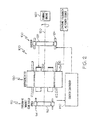
- FIG. 1 is a functional block diagram of an exemplary high speed stmer-gmeroor system according to an embodiment of the present invention when operating in a generator mode;
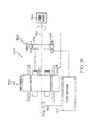
- FIG. 2 is a functional block diagram of the exemplary high speed starter-generator system of FIG. 1, when operating in a motor mode;
- FIG. 3 is a functional block diagram of the exemplary high speed starter-generator system of FIGS. 1 and 2, according to an alternative embodiment of the present invention
- FIG. 4 is a perspective view of a physical embodiment of the high speed starter-generators shown in FIGS. 1-3;
- FIG. 5 is a schematic representation of at least a portion of the high speed starter-generators of FIGS. 1-3,
- starter-generator is described herein as being used with, for example, an aircraft gas turbine engine, it will be appreciated that may be used as a starter-generator with gas turbine engines in numerous other environments included, for example, space, marine, land, or other vehicle-related applications where gas turbine engines are used.
- FIG. 1 a functional schematic block diagram of an exemplary starter-generator system 100 for use with, for example, an aircraft gas turbine engine, is shown.
- This exemplary starter-generator system 100 includes a permanent magnet generator (PMG) 110, which includes a PMG rotor 112 and a PMG stator 114, an exciter 120, which includes an exciter rotor 122 and an exciter stator 124, a main starter-generator 130, which includes a main rotor 132 and a main stator 134, and an exciter controller 140.
- PMG permanent magnet generator
- the starter-generator system 100 may include one or more additional components, sensors, or controllers. However, a description of these additional components, sensors, and controllers, if included, is not needed, and will therefore not be further depicted or described,
- the PMG rotor 112, the exciter rotor 122, and the main rotor 132 are all mounted on a common shaft 150.
- the shaft 150 receives a rotational drive force from, for example, an aircraft gas turbine engine 160, which causes the PMG rotor 112, the exciter rotor 122, and the main rotor 132 to all rotate at the same rotational speed.
- the rotational speed of the engine 160, and these starter-generator system components may vary.
- the rotational speed may vary in the range of about 1,200 rpm to about 4,800 rpm.
- this rotational speed range is merely exemplary, and that various other speed ranges may be used. It will be further appreciated that the relative positions of the PMG 110, the exciter 120, and the main starter-generator 130 may differ. For example, the exciter generator 120 could be located between PMG 110 and main starter-generator 130, just to describe a single alternative configuration.
- the PMG 110 generates and supplies, via the PMG stator 114, AC power to the exciter controller 140.
- the exciter controller 140 supplies AC power to the exciter stator 124.
- this causes the exciter rotor 122 to supply AC power to the main rotor 132.
- the main rotor 132 rotates, it induces AC current in a main stator 134, which is in turn supplied to one or more loads.
- the main stator 134 is coupled to receive AC power from a constant frequency AC power source 202.
- the constant frequency AC power source 202 may vary, and may include, for example, an aircraft auxiliary power unit (APU) or an external power source.
- APU aircraft auxiliary power unit
- the AC power generates a rotating magnetic field in windings of the main stator 134. This rotating magnetic field induces currents in windings of the main rotor 132. As will be described further below, the induced currents are also supplied to windings of the exciter rotor 122.
- the interaction of the induced currents and rotating magnetic field generates a torque and causes the main rotor 132 to rotate and supply rotational power to the engine 160. Because the exciter rotor 122, and the PMG rotor 112 are also mounted on the shaft 150, these components also rotate. As will also be described further below, during motor mode operation, the exciter controller 140 is configured to selectively supply AC power to the exciter stator 124, which in turn causes the exciter rotor 122 to supply AC power to the main rotor 132, to thereby control the torque that the main rotor 132 generates.
- the starter-generator system 100 described above is implemented with a PMG 110
- the starter-generator system 100 could alternatively be implemented without the PMG 110.
- the starter-generator system 100 includes a speed sensor 302 rather than the PMG 110.
- the speed sensor 302 which may be implemented using any one of numerous types of rotational speed sensors, is typically used during operation in the generator mode and is configured to sense the rotational speed of the shaft 150 and supply a speed signal (N 5 ) representative thereof to the exciter controller 140.
- the exciter controller 140 in the alternative embodiment also supplies AC power to the exciter stator 124 during generator mode operation, it does so in response to the speed signal from the speed sensor 302 rather than in response to the AC power supplied from the PMG 110.
- the signal supplied to the exciter controller 140 is representative of shaft rotational speed.
- the exciter controller 140 can be configured to receive the AC power signal from the PMG 110, the speed signal from the speed sensor 302, or no signal at all that is representative of shaft rotational speed,
- the starter-generator system 100 is preferably housed within a generator housing 402, a perspective view of which is illustrated in FIG. 4.
- the exemplary starter-generator systems 100 described above and shown in FIGS. 1-3 are, in some aspects, configured similar to conventional brushless starter-generators; however, each is quite different in certain other aspects.
- the exciter rotor 122 and the main stator 134 are both implemented similar to a conventional brushless AC generator, whereas the exciter stator 124 and main rotor 132 are not.
- the exciter rotor 122 and the main stator 134 are both implemented with multiphase (e.g., three-phase) exciter rotor windings 502 and multi-phase (e.g., three-phase) main stator windings 504, respectively.
- the exciter stator 124 and the main rotor 132 are implemented with multi-phase (e.g., three-phase) exciter stator windings 506 and multi-phase (e.g., three-phase) main rotor field windings 508, respectively.
- the exciter controller 140 is implemented, at least in part, as a power converter circuit that is configured to supply variable-frequency, variable-voltage, three-phase excitation to the exciter stator windings 506. It will be appreciated that that when the starter-generator 100 is operating in the motor mode, the exciter controller 140, as mentioned above, may be configured to supply excitation to the exciter stator windings 506, based on one or more predetermined torque profiles stored in a memory 512 within, or external to, the exciter controller 140, or in response to a signal supplied to the exciter controller 140 from either the PMG 110 or the speed sensor 202, or one or more combinations of stored profiles and signals supplied to the exciter controller 140,
- the frequency and phase of the excitation that the exciter controller 140 supplies to the exciter stator windings 506 when the starter-generator system 100 is operating in the generator mode depends upon the rotational speed at which the engine 160 is rotating the shaft 150 (and thus the PMG rotor 112, the rotor 122, and the main rotor 132), upon the number of poles with which the exciter 120 and the main starter-generator 130 are implemented, and upon the desired frequency that the starter-generator system 100 is to supply.
- a detailed description of the operation of the starter-gentratot system 100 in the generator mode is described in more detail in U.S. Patent Application Serial No. 11/111,084, filed April 20, 2005 , and assigned to the assignee of the present invention. Hence, a description of operation in the generator mode will not be included herein. Rather, only a description of the operation of the starter-generator system 100 in the motor mode will be provided.
- the frequency and voltage of the excitation that the exciter controller 140 supplies to the exciter stator windings 506 when the starter-generator system 100 is operating in the motor mode depends upon the torque to be generated and supplied to the engine 160, upon the number of poles with which the exciter 120 and the main starter-generator 130 are implemented, and upon the frequency and voltage supplied to the main stator 134.
- the exciter 120 is implemented as a 10-pole machine
- the main starter-generator 130 is implemented as a 4-pole machine
- the constant frequency supplied to the main stator 134 is 400 Hz.
- the exciter 120 and main starter-generator 130 could be implemented with different numbers of poles, and the main stator could be supplied with AC power at a different, albeit constant, frequency. It will additionally be appreciated that in some embodiments, the starter-generator system 100 may be operated in the motor mode without the exciter controller 140 supplying any excitation to the exciter stator windings 506, during either a portion of an engine sequence or throughout an entire engine start sequence.
- the starter-generator system 100 when operating in the motor mode, may be configured to operate as either a synchronous motor or an asynchronous motor.
- a synchronous motor is one in which the rotational speed of the main rotor 132 matches the rotational speed of the rotating magnetic flux in the stator 134
- an asynchronous motor is one in which the rotational speed of the main rotor 132 is less than the rotational speed of the rotating magnetic field in the main stator 134.
- the starter-generator system 100 may be configured to operate as a synchronous motor during one or more phases of an engine start sequence, and as an asynchronous motor during one or more different phases of an engine start sequence.
- the torque generated by the main rotor 132 and supplied to the engine 160 may be controlled by controlling the supply voltage magnitude from the constant frequency AC power source to the main starter-generator stator 134, controlling the frequency of the excitation supplied from the exciter controller 140 to the exciter stator windings 506, controlling the voltage magnitude of the excitation supplied from the exciter controller to the exciter stator windings 506, or controlling various combinations of these parameters.
- the torque generated thereby and supplied to the engine 160 may be controlled by controlling both the frequency and the voltage magnitude of the excitation supplied from the exciter controller 140 to the exciter stator windings 506.
- the starter-generator system 100 When the starter-generator system 100 is configured to operate either synchronously or asynchronously, and the torque is being controlled by the exciter controller 140, the main rotor windings 508 will be excited by the rotating electromagnetic field that is generated by the main stator windings 504 and will be supplied with non-rectified excitation currents induced in the exciter rotor windings 502.
- the rotating electromagnetic field excitation will, as is generally known, induce currents in the main rotor windings 508.
- the induced currents in combination with the non-rectified currents supplied to the main rotor windings 508 from the exciter rotor windings 502, will generate a torque and cause the main rotor 132, exciter rotor 122, and shaft 150 to rotate and drive the engine 160.
- the generated torque is controlled.
- the AC starter-generator system described herein generates a torque for supply to a gas turbine engine when the starter-generator is operating in a motor mode, by independently controlling the field rotational speeds.
- the disclosed starter-generator system can be implemented with no restrictions on the number of poles for the exciter or main starter-generator.
Abstract
Description
- The present invention relates to rotating electrical machines such as starter-generators for gas turbine engines and, more particularly, to a brushless starter-generator with an independently controllable exciter field.
- An aircraft may include various types of rotating electrical machines such as, for example, generators, motors, and motor/generators. Motor/generators are used as staiter-generators in some aircraft, since this type of rotating electrical machine may be operated in both a motor mode and a generator mode. A starter-generator may be used to start the engines or auxiliary power unit (APU) of an aircraft when operating as a motor, and to supply electrical power to the aircraft power distribution system when operating as a generator. Thus, when operating as a motor, a starter-generator may be used to start the engines.
- One particular type of aircraft starter-generator includes three separate brushless generators, namely, a permanent magnet generator (PMG), an exciter generator, and a motor/generator. The PMG includes permanent magnets on its rotor. When the PMG rotor rotates, AC currents are induced in stator windings of the PMG. These AC currents are typically fed to a regulator or a control device, which in turn outputs a DC current if the starter-generator is operating in a generator mode. Conversely, if the starter-generator is operating in a motor mode, the control device supplies AC power.
- If the starter-gesemtor is operating in the generator mode, DC current from the regulator or control device is supplied to stator windings of the exciter. As the exciter rotor rotates, three phases of AC current are typically induced in the exciter rotor windings. Rectifier circuits that rotate with the exciter rotor rectify this three-phase AC current, and the resulting DC currents are provided to the rotor windings of the main motor/generator. Finally, as the main motor/generator rotor rotates, three phases of AC current are typically induced in the main motor/generator stator, and this three-phase AC output can then be provided to a load.
- If the starter-generator is operating in the motor mode, AC power from the control device is supplied to the exciter stator. This AC power induces, via a transformer effect, an electromagnetic field in the exciter armature, whether the exciter rotor is stationary or rotating. The AC currents produced by this induced field are rectified by the rectifier circuits and supplied to the main motor/generator rotor, which produces a DC field in the rotor. Variable frequency AC power is supplied from the control device to the main motor/generator stator. This AC power produces a rotating magnetic field in the main stator, which causes the main rotor to rotate and supply mechanical output power.
- The above-described starter-generator can potentially provide overall weight savings and improved operating costs in, for example, a More Electric Aircraft (MEA) system architecture. It is noted, however, that the starter-generator in such architectures may be used to start the aircraft main engines, and may thus need to generate a starting torque that is significantly higher than for existing auxiliary power unit (APU) starter-generator applications. Current starter-generators typically include relatively complex and heavy power electronics circuits in the control device, For example, some control devices may include inverters, for converting DC to AC power, rectifiers, for converting AC power to DC power, and potentially complex voltage and frequency control circuits, which can increase overall complexity, cost, and maintenance, Although brush-type DC machines may alleviate the need for some of these complex and heavy electronic circuits, these also suffer certain drawbacks. For example, the brushes tend to wear fairly quickly, which can reduce machine reliability and increase the need for periodic maintenance and cleaning. Some brush-type DC machines can also suffer what is known as torque ripple during startup. In some instances, the torque ripple can be large, which can result in poor starter performance.
- Hence, there is a need for a starter-generator that does not rely on relatively complex and heavy inverters and frequency control circuits for proper operation, and/or does not suffer reduced reliability from brush wear, and/or the need for potentially frequent maintenance and cleaning, and/or does not experience significant torque ripple during startup. The present invention addresses one or more of these needs.
- The present invention provides a starter-generator system that supplies a controllable torque to a gas turbine engine, to thereby assist in starting the gas turbine engine, by independently controlling excitation frequency and/or voltage magnitude.
- In one embodiment, and by way of example only, a starter-generator includes a multi-phase exciter stator, a rotationally mounted multi-phase exciter rotor, a multi-phase main stator, a rotationally mounted multi-phase main rotor, and an exciter controller, The multi-phase exciter stator has a plurality of exciter stator windings wound thereon that, upon electrical excitation thereof, generate a rotating exciter stator electromagnetic flux, The rotationally mounted multi-phase exciter rotor is disposed at least partially within the multi-phast exciter stator, and has a plurality of exciter rotor windings wound thereon that, upon excitation thereof with the rotating exciter stator exciter flux, have non-rectified excitation currents induced therein. The multi-phase main stator has a plurality of main stator windings wound thereon that, upon electrical excitation thereof from main AC power source, generate a rotating main stator electromagnetic flux. The rotationally mounted multi-phase main rotor is disposed at least partially within the multi-phase main stator and is mechanically coupled to the exciter rotor. The multi-phase main rotor has a plurality of main rotor windings wound thereon that are electrically connected to receive the non-rectified excitation currents induced in the exciter rotor windings and that, upon excitation thereof with the main stator rotating electromagnetic flux and in response to the non-rectified excitation currents supplied thereto, have currents induced therein that generate a main rotor torque to thereby cause the multi-phase main rotor and the multi-phase exciter rotor to rotate. The exciter controller is electrically coupled to at least the exciter stator windings and is configured to selectively supply the electrical excitation thereto, to thereby selectively control the generated main rotor torque.
- In yet another exemplary embodiment, a starter-generator includes a multi-phase exciter stator, a multi-phase exciter rotor, a multi-phase main stator, and a multi-phase main rotor. The multi-phase exciter stator has a plurality of exciter stator windings wound thereon. The multi-phase exciter rotor is rotationally mounted, is disposed at least partially within the multi-phase exciter stator, and has a plurality of exciter rotor windings wound thereon. The multi-phase main stator has a plurality of main stator windings wound thereon that upon electrical excitation thereof from a main AC power source, generate a rotating main stator electromagnetic flux. The multi-phase main rotor is rotationally mounted, is disposed at least partially within the multi-phase stator, and is mechanically coupled to the exciter rotor. The multi-phase main rotor further has a plurality of main rotor windings wound thereon that are directly connected to the exciter rotor windings and upon excitation thereof with the main stator rotating electromagnetic flux, have currents induced therein that generate a main rotor torque to thereby cause the multi-phase main rotor and the multi-phase exciter rotor to rotate,
- Other independent features and advantages of the preferred starter-generator system and method will become apparent from the following detailed description, taken in conjunction with the accompanying drawings which illustrate, by way of example, the principles of the invention.
In the Drawings - FIG. 1 is a functional block diagram of an exemplary high speed stmer-gmeroor system according to an embodiment of the present invention when operating in a generator mode;
- FIG. 2 is a functional block diagram of the exemplary high speed starter-generator system of FIG. 1, when operating in a motor mode;
- FIG. 3 is a functional block diagram of the exemplary high speed starter-generator system of FIGS. 1 and 2, according to an alternative embodiment of the present invention;
- FIG. 4 is a perspective view of a physical embodiment of the high speed starter-generators shown in FIGS. 1-3; and
- FIG. 5 is a schematic representation of at least a portion of the high speed starter-generators of FIGS. 1-3,
- The following detailed description of the invention is merely exemplary in nature and is not intended to limit the invention or the application and uses of the invention. Furthermore, there is no intention to be bound by any theory presented in the preceding background of the invention or the following detailed description of the invention. In this regard, although the starter-generator is described herein as being used with, for example, an aircraft gas turbine engine, it will be appreciated that may be used as a starter-generator with gas turbine engines in numerous other environments included, for example, space, marine, land, or other vehicle-related applications where gas turbine engines are used.
- Turning now to the description and with reference first to FIG. 1, a functional schematic block diagram of an exemplary starter-
generator system 100 for use with, for example, an aircraft gas turbine engine, is shown. This exemplary starter-generator system 100 includes a permanent magnet generator (PMG) 110, which includes aPMG rotor 112 and aPMG stator 114, anexciter 120, which includes anexciter rotor 122 and anexciter stator 124, a main starter-generator 130, which includes amain rotor 132 and amain stator 134, and anexciter controller 140. It will be appreciated that the starter-generator system 100 may include one or more additional components, sensors, or controllers. However, a description of these additional components, sensors, and controllers, if included, is not needed, and will therefore not be further depicted or described, - In the depicted embodiment, the
PMG rotor 112, theexciter rotor 122, and themain rotor 132 are all mounted on acommon shaft 150. When the starter-generator system 100 is operating in a generator mode, theshaft 150 receives a rotational drive force from, for example, an aircraftgas turbine engine 160, which causes thePMG rotor 112, theexciter rotor 122, and themain rotor 132 to all rotate at the same rotational speed. The rotational speed of theengine 160, and these starter-generator system components, may vary. For example, the rotational speed may vary in the range of about 1,200 rpm to about 4,800 rpm. It will be appreciated that this rotational speed range is merely exemplary, and that various other speed ranges may be used. It will be further appreciated that the relative positions of thePMG 110, the exciter 120, and the main starter-generator 130 may differ. For example, theexciter generator 120 could be located betweenPMG 110 and main starter-generator 130, just to describe a single alternative configuration. - No matter the specific rotational speed range, it will be appreciated that as the
PMG rotor 112 rotates, thePMG 110 generates and supplies, via thePMG stator 114, AC power to theexciter controller 140. In response, theexciter controller 140 supplies AC power to theexciter stator 124. In turn, this causes theexciter rotor 122 to supply AC power to themain rotor 132. As themain rotor 132 rotates, it induces AC current in amain stator 134, which is in turn supplied to one or more loads. - As depicted in FIG. 2, when the starter-
generator system 100 is operating in the motor mode, themain stator 134 is coupled to receive AC power from a constant frequency AC power source 202. It will be appreciated that the constant frequency AC power source 202 may vary, and may include, for example, an aircraft auxiliary power unit (APU) or an external power source. No matter the specific source of the constant frequency AC power, it will be appreciated that the AC power generates a rotating magnetic field in windings of themain stator 134. This rotating magnetic field induces currents in windings of themain rotor 132. As will be described further below, the induced currents are also supplied to windings of theexciter rotor 122. In any case, the interaction of the induced currents and rotating magnetic field generates a torque and causes themain rotor 132 to rotate and supply rotational power to theengine 160. Because theexciter rotor 122, and thePMG rotor 112 are also mounted on theshaft 150, these components also rotate. As will also be described further below, during motor mode operation, theexciter controller 140 is configured to selectively supply AC power to theexciter stator 124, which in turn causes theexciter rotor 122 to supply AC power to themain rotor 132, to thereby control the torque that themain rotor 132 generates. - Before proceeding further, it will be appreciated that although the starter-
generator system 100 described above is implemented with aPMG 110, the starter-generator system 100 could alternatively be implemented without thePMG 110. In this alternative embodiment, which is shown in FIG. 3, the starter-generator system 100 includes a speed sensor 302 rather than thePMG 110. The speed sensor 302, which may be implemented using any one of numerous types of rotational speed sensors, is typically used during operation in the generator mode and is configured to sense the rotational speed of theshaft 150 and supply a speed signal (N5) representative thereof to theexciter controller 140. Although theexciter controller 140 in the alternative embodiment also supplies AC power to theexciter stator 124 during generator mode operation, it does so in response to the speed signal from the speed sensor 302 rather than in response to the AC power supplied from thePMG 110. In both embodiments, however, it is noted that the signal supplied to theexciter controller 140, be it the AC power signal from thePMG 110 or the speed signal from the speed sensor 302, is representative of shaft rotational speed. It is additionally noted that in both embodiments, when the starter-generator is operating in the motor mode, theexciter controller 140 can be configured to receive the AC power signal from thePMG 110, the speed signal from the speed sensor 302, or no signal at all that is representative of shaft rotational speed, - No matter whether the starter-
generator system 100 is implemented as shown in FIGS. 1 and 2, or FIG. 3, the starter-generator system 100, or at least portions of thesystem 100, is preferably housed within agenerator housing 402, a perspective view of which is illustrated in FIG. 4. - The exemplary starter-
generator systems 100 described above and shown in FIGS. 1-3 are, in some aspects, configured similar to conventional brushless starter-generators; however, each is quite different in certain other aspects. For example, and with reference now to FIG. 5, it is seen that theexciter rotor 122 and themain stator 134 are both implemented similar to a conventional brushless AC generator, whereas theexciter stator 124 andmain rotor 132 are not. In particular, theexciter rotor 122 and themain stator 134, as in a conventional brushless AC starter-generator, are both implemented with multiphase (e.g., three-phase)exciter rotor windings 502 and multi-phase (e.g., three-phase)main stator windings 504, respectively. Conversely, theexciter stator 124 and themain rotor 132, rather than being implemented with single phase windings, as in a conventional brushless AC starter-generator, are implemented with multi-phase (e.g., three-phase)exciter stator windings 506 and multi-phase (e.g., three-phase) mainrotor field windings 508, respectively. Another difference from a conventional brushless AC starter-generator system is that there are no rotating rectifier assemblies coupled between theexciter rotor 122 and themain rotor 132. Rather, theexciter rotor windings 502 are directly electrically coupled to the mainrotor field windings 508. - The
exciter controller 140 is implemented, at least in part, as a power converter circuit that is configured to supply variable-frequency, variable-voltage, three-phase excitation to theexciter stator windings 506. It will be appreciated that that when the starter-generator 100 is operating in the motor mode, theexciter controller 140, as mentioned above, may be configured to supply excitation to theexciter stator windings 506, based on one or more predetermined torque profiles stored in amemory 512 within, or external to, theexciter controller 140, or in response to a signal supplied to theexciter controller 140 from either thePMG 110 or the speed sensor 202, or one or more combinations of stored profiles and signals supplied to theexciter controller 140, - The frequency and phase of the excitation that the
exciter controller 140 supplies to theexciter stator windings 506 when the starter-generator system 100 is operating in the generator mode depends upon the rotational speed at which theengine 160 is rotating the shaft 150 (and thus thePMG rotor 112, therotor 122, and the main rotor 132), upon the number of poles with which theexciter 120 and the main starter-generator 130 are implemented, and upon the desired frequency that the starter-generator system 100 is to supply. A detailed description of the operation of the starter-gentratot system 100 in the generator mode is described in more detail inU.S. Patent Application Serial No. 11/111,084, filed April 20, 2005 generator system 100 in the motor mode will be provided. - The frequency and voltage of the excitation that the
exciter controller 140 supplies to theexciter stator windings 506 when the starter-generator system 100 is operating in the motor mode depends upon the torque to be generated and supplied to theengine 160, upon the number of poles with which theexciter 120 and the main starter-generator 130 are implemented, and upon the frequency and voltage supplied to themain stator 134. For example, in a particular physical embodiment, theexciter 120 is implemented as a 10-pole machine, the main starter-generator 130 is implemented as a 4-pole machine, and the constant frequency supplied to themain stator 134 is 400 Hz. It will be appreciated, however, that this is merely exemplary of a particular embodiment, and that theexciter 120 and main starter-generator 130 could be implemented with different numbers of poles, and the main stator could be supplied with AC power at a different, albeit constant, frequency. It will additionally be appreciated that in some embodiments, the starter-generator system 100 may be operated in the motor mode without theexciter controller 140 supplying any excitation to theexciter stator windings 506, during either a portion of an engine sequence or throughout an entire engine start sequence. - In addition to the above, it will be appreciated that the starter-
generator system 100, when operating in the motor mode, may be configured to operate as either a synchronous motor or an asynchronous motor. As is generally known, a synchronous motor is one in which the rotational speed of themain rotor 132 matches the rotational speed of the rotating magnetic flux in thestator 134, and an asynchronous motor is one in which the rotational speed of themain rotor 132 is less than the rotational speed of the rotating magnetic field in themain stator 134. It will be further appreciated that the starter-generator system 100 may be configured to operate as a synchronous motor during one or more phases of an engine start sequence, and as an asynchronous motor during one or more different phases of an engine start sequence. - When the starter-
generator system 100 is configured to operate asynchronously, the torque generated by themain rotor 132 and supplied to theengine 160 may be controlled by controlling the supply voltage magnitude from the constant frequency AC power source to the main starter-generator stator 134, controlling the frequency of the excitation supplied from theexciter controller 140 to theexciter stator windings 506, controlling the voltage magnitude of the excitation supplied from the exciter controller to theexciter stator windings 506, or controlling various combinations of these parameters. Conversely, when the starter-generator system 100 is configured to operate synchronously, the torque generated thereby and supplied to theengine 160 may be controlled by controlling both the frequency and the voltage magnitude of the excitation supplied from theexciter controller 140 to theexciter stator windings 506. - When the starter-
generator system 100 is configured to operate either synchronously or asynchronously, and the torque is being controlled by theexciter controller 140, themain rotor windings 508 will be excited by the rotating electromagnetic field that is generated by themain stator windings 504 and will be supplied with non-rectified excitation currents induced in theexciter rotor windings 502. The rotating electromagnetic field excitation will, as is generally known, induce currents in themain rotor windings 508. The induced currents, in combination with the non-rectified currents supplied to themain rotor windings 508 from theexciter rotor windings 502, will generate a torque and cause themain rotor 132,exciter rotor 122, andshaft 150 to rotate and drive theengine 160. Thus, by controlling the non-rectified currents supplied to themain rotor windings 508 from theexciter rotor windings 502, by varying either the frequency or the voltage magnitude of the excitation supplied to theexciter stator windings 506 when operated asynchronously, or by varying both the frequency and the voltage magnitude of the excitation supplied to thestator windings 506 when operated synchronously, the generated torque is controlled. - The AC starter-generator system described herein generates a torque for supply to a gas turbine engine when the starter-generator is operating in a motor mode, by independently controlling the field rotational speeds. The disclosed starter-generator system can be implemented with no restrictions on the number of poles for the exciter or main starter-generator.
- While the invention has been described with reference to a preferred embodiment, it will be understood by those skilled in the art that various changes may be made and equivalents may be substituted for elements thereof without departing from the scope of the invention. In addition, many modifications may be made to adapt to a particular situation or material to the teachings of the invention without departing from the essential scope thereof. Therefore, it is intended that the invention not be limited to the particular embodiment disclosed as the best mode contemplated for carrying out this invention, but that the invention will include an embodiments falling within the scope of the appended claims.
Claims (9)
- A starter-generator (100), comprising:a multi-phase exciter stator (124) having a plurality of exciter stator windings (506) wound thereon that, upon electrical excitation thereof, generate a rotating exciter stator electromagnetic flux;a rotationally mounted multi-phase exciter rotor (122) disposed at least partially within the multi-phase exciter stator (124), the multi-phase exciter rotor (122) having a plurality of exciter rotor windings (502) wound thereon that, upon excitation thereof with the rotating exciter stator electromagnetic exciter flux, have non-rectified excitation currents induced therein;a multi-phase main stator (134) having a plurality of main stator windings (504) wound thereon that, upon electrical excitation thereof from a main AC power source (202), generate a rotating main stator electromagnetic flux;a rotationally mounted multi-phase main rotor (132) disposed at least partially within the multi-phase main stator (134) and mechanically coupled to the exciter rotor (122), the multi-phase main rotor (132) having a plurality of main rotor windings (508) wound thereon that are electrically connected to receive the non-rectified excitation currents induced in the exciter rotor windings (502) and that, upon excitation thereof with the main stator rotating electromagnetic flux and in response to the non-rectified excitation currents supplied thereto, have currents induced therein that generate a main rotor torque to thereby cause the multi-phase main rotor (132) and the multi-phase exciter rotor (122) to rotate; andan exciter controller (140) electrically coupled to at least the exciter stator windings (506) and configured to selectively supply the electrical excitation thereto, to thereby selectively control the generated main rotor torque.
- The starter-generator (100) of Claim 1, wherein:the currents induced in the main rotor windings (508) further generate a main rotor flux that rotates at a rotational rotor flux speed; andthe exciter controller (140) is configured to selectively control the generated main rotor torque by selectively supplying electrical excitation to the exciter stator windings (5 06) that controls the rotational rotor flux speed:
- The starter-generator (100) of Claim 2, wherein the exciter controller (140) is configured to:selectively supply the electrical excitation as multi-phase AC excitation having a frequency and a phase sequence; andcontrol the frequency and phase sequence to thereby control the rotational rotor flux speed.
- The starter-generator (100) of Claim 3, wherein:the multi-phase main rotor (132) and the multi-phase exciter rotor (122), in response to generation of the main rotor torque, rotate in a first direction, andthe exciter controller (140) is configured to supply the multi-phase AC electrical excitation to the exciter stator windings (506) in a phase sequence that is in either the first direction or a second direction opposite the first direction.
- The starter-generator (100) of Claim 3, wherein,the rotating main stator electromagnetic flux rotates at a rotational stator flux speed; andthe exciter controller (140) is configured to selectively supply the electrical excitation to the exciter stator windings (506) to thereby control the rotational rotor flux speed to be substantially equal to or less than the rotational stator flux speed.
- The starter-generator (100) of Claim 1, wherein the main AC power source (202) is a constant frequency AC power source (202).
- The starter-generator (100) of Claim 1, further comprising:a permanent magnet generator (PMG) (110) mounted on the shaft (150) and configured, upon station thereof to supply a signal to the exciter controller (140) that is representative of multi-phase main rotor rotational speed,wherein the exciter controller (140) determines the multi-phase main rotor rotational speed based at least in part on the signal supplied from the PMG (110),
- The starter-generator (100) of Claim 1, further comprising:a speed sensor (302) configured to sense multi-phase main rotor rotational speed and supply a speed signal representative thereof to the exciter controller (140),wherein the exciter controller (140) determines the multi-phase main rotor rotational speed based at least in part on the speed signal.
- The starter-generator (100) of Claim 1, wherein:the main generator rotor is implemented as a N-pole rotor;the exciter rotor (122) is implemented as a M-pole rotor; andN and M are each integers greater than one.
Applications Claiming Priority (1)
| Application Number | Priority Date | Filing Date | Title |
|---|---|---|---|
| US11/360,116 US7301311B2 (en) | 2006-02-22 | 2006-02-22 | Brushless starter-generator with independently controllable exciter field |
Publications (2)
| Publication Number | Publication Date |
|---|---|
| EP1826890A2 true EP1826890A2 (en) | 2007-08-29 |
| EP1826890A3 EP1826890A3 (en) | 2008-04-09 |
Family
ID=38068544
Family Applications (1)
| Application Number | Title | Priority Date | Filing Date |
|---|---|---|---|
| EP07102815A Ceased EP1826890A3 (en) | 2006-02-22 | 2007-02-21 | Brushless starter-generator with independently controllable exciter field. |
Country Status (2)
| Country | Link |
|---|---|
| US (1) | US7301311B2 (en) |
| EP (1) | EP1826890A3 (en) |
Cited By (4)
| Publication number | Priority date | Publication date | Assignee | Title |
|---|---|---|---|---|
| WO2010135030A3 (en) * | 2009-05-19 | 2011-09-01 | General Electric Company | Aircraft engine starting/generating system and method of control |
| GB2504754A (en) * | 2012-08-09 | 2014-02-12 | Safran Power Uk Ltd | Aircraft engine starter motor control |
| CN103795307A (en) * | 2012-10-31 | 2014-05-14 | 通用电气航空系统有限责任公司 | Method for starting an electric motor |
| EP3562028A1 (en) * | 2018-04-23 | 2019-10-30 | The Boeing Company | Externally modulated independent speed variable frequency generator |
Families Citing this family (18)
| Publication number | Priority date | Publication date | Assignee | Title |
|---|---|---|---|---|
| US7508086B2 (en) * | 2006-03-24 | 2009-03-24 | General Electric Company | Aircraft engine starter/generator and controller |
| US7514806B2 (en) * | 2007-06-05 | 2009-04-07 | Honeywell International Inc. | Engine start system with quadrature AC excitation |
| US7863868B2 (en) * | 2007-06-05 | 2011-01-04 | Honeywell International Inc. | Generator with quadrature AC excitation |
| US7977925B2 (en) * | 2008-04-04 | 2011-07-12 | General Electric Company | Systems and methods involving starting variable speed generators |
| US7466109B1 (en) * | 2008-04-07 | 2008-12-16 | General Electric Company | Systems and methods involving variable speed generators |
| US8450888B2 (en) * | 2009-04-20 | 2013-05-28 | General Electric Company | Integrated brushless starter/generator system |
| EP2704310B1 (en) * | 2012-08-28 | 2019-02-13 | GE Renewable Technologies | Method for operating such an electrical machine |
| US9257889B2 (en) * | 2013-03-15 | 2016-02-09 | Hamilton Sundstrand Corporation | EPGS architecture with multi-channel synchronous generator and common field regulated exciter |
| US9209741B2 (en) * | 2014-02-24 | 2015-12-08 | The Boeing Company | Method and system for controlling synchronous machine as generator/starter |
| US9450527B2 (en) | 2014-03-05 | 2016-09-20 | Honeywell International Inc. | Controlled frequency generator with optimized power factor |
| US9882518B2 (en) | 2014-07-08 | 2018-01-30 | Generac Power Systems, Inc. | Auxiliary winding for a generator |
| US10305356B2 (en) | 2014-09-26 | 2019-05-28 | The Boeing Company | Synchronous machine with common motor/generator exciter stage |
| US9660563B2 (en) | 2015-06-19 | 2017-05-23 | Hamilton Sundstrand Corporation | High voltage direct current system with improved generator excitation |
| AT517397B1 (en) * | 2015-07-07 | 2017-10-15 | Ge Jenbacher Gmbh & Co Og | Arrangement with a synchronous generator and an asynchronous machine |
| US10472084B2 (en) | 2016-03-21 | 2019-11-12 | Honeywell International Inc. | Motor-generator for high efficiency auxiliary power system |
| US10794216B2 (en) * | 2018-06-19 | 2020-10-06 | Raytheon Technologies Corporation | Fan drive gear system DC motor and generator |
| US10723469B2 (en) | 2018-09-21 | 2020-07-28 | Hamilton Sunstrand Corporation | System and method for driving electrically driving a gas turbine engine via a wound field synchronous machine assisted by a PMG |
| EP3792177B1 (en) * | 2019-09-10 | 2022-08-03 | Ratier-Figeac SAS | System comprising a brushless direct current electric motor for a propeller engine |
Citations (4)
| Publication number | Priority date | Publication date | Assignee | Title |
|---|---|---|---|---|
| GB975102A (en) | 1960-01-27 | 1964-11-11 | English Electric Co Ltd | Improvements relating to electric generating apparatus |
| US20040080300A1 (en) | 2002-10-23 | 2004-04-29 | Mingzhou Xu | Gas turbine engine starter-generator exciter starting system and method |
| US20050180862A1 (en) | 2003-09-11 | 2005-08-18 | Airbus France | Fixed frequency electrical generation system and corresponding control procedure |
| US20060087293A1 (en) | 2004-10-26 | 2006-04-27 | Honeywell International, Inc. | AC generator with independently controlled field rotational speed |
Family Cites Families (28)
| Publication number | Priority date | Publication date | Assignee | Title |
|---|---|---|---|---|
| US4536126A (en) | 1970-12-18 | 1985-08-20 | Westinghouse Electric Corp. | System and method employing a digital computer for automatically synchronizing a gas turbine or other electric power plant generator with a power system |
| US3676764A (en) | 1971-01-29 | 1972-07-11 | Kohler Co | Brushless alternating current generator |
| CH544447A (en) | 1972-02-07 | 1973-11-15 | Bbc Brown Boveri & Cie | Starting device for a synchronous machine |
| US3908161A (en) * | 1974-02-07 | 1975-09-23 | Gen Electric | Field excitation system for synchronous machines utilizing a rotating transformer brushless exciter generating combination |
| US4093869A (en) | 1976-04-13 | 1978-06-06 | Westinghouse Electric Corp. | Quadrature axis field brushless exciter |
| US4219739A (en) | 1978-04-27 | 1980-08-26 | Lear Avia Corporation | Starter motor-alternator apparatus |
| US4473752A (en) | 1982-05-27 | 1984-09-25 | Lockheed Corporation | Aircraft engine starting with synchronous ac generator |
| US4743777A (en) | 1986-03-07 | 1988-05-10 | Westinghouse Electric Corp. | Starter generator system with two stator exciter windings |
| US4786852A (en) | 1986-07-18 | 1988-11-22 | Sundstrand Corporation | Inverter operated turbine engine starting system |
| US4743776A (en) | 1986-09-02 | 1988-05-10 | Sundstrand Corporation | Starter-generator for engines |
| JPS6430500A (en) | 1987-07-24 | 1989-02-01 | Shinko Electric Co Ltd | Brushless starting generator exciter |
| US4830412A (en) * | 1987-10-26 | 1989-05-16 | Sundstrand Corporation | Starting system and method using a hybrid permanent magnet/induction machine |
| US5028803A (en) * | 1989-03-22 | 1991-07-02 | Sundstrand Corporation | Integrated drive generator system with direct motor drive prime mover starting |
| US4939441A (en) * | 1989-10-27 | 1990-07-03 | Sundstrand Corporation | Excitation system for a brushless generator having separate AC and DC exciter field windings |
| US5068590A (en) * | 1989-12-20 | 1991-11-26 | Sundstrand Corporation | Brushless generator having AC excitation in generating and starting modes |
| GB9412410D0 (en) * | 1994-06-21 | 1994-08-10 | Lucas Ind Plc | Control circuit for electrical generator |
| US6628104B2 (en) | 2001-02-08 | 2003-09-30 | Honeywell International Inc. | Load-off transient acceleration generator control apparatus/method |
| EP1289118A1 (en) * | 2001-08-24 | 2003-03-05 | Siemens Aktiengesellschaft | Method and arrangement for starting a turbo set |
| US6838779B1 (en) * | 2002-06-24 | 2005-01-04 | Hamilton Sundstrand Corporation | Aircraft starter generator for variable frequency (vf) electrical system |
| US6768278B2 (en) | 2002-08-06 | 2004-07-27 | Honeywell International, Inc. | Gas turbine engine starter generator with switchable exciter stator windings |
| US6906479B2 (en) | 2002-08-06 | 2005-06-14 | Honeywell International, Inc. | Gas turbine engine starter generator with multiple windings on each exciter stator pole |
| US6791204B2 (en) | 2002-09-20 | 2004-09-14 | Honeywell International Inc. | Torque generation for salient-pole synchronous machine for start-up of a prime mover |
| US6847194B2 (en) * | 2002-09-20 | 2005-01-25 | Honeywell International Inc. | Electric start for a prime mover |
| US6933704B2 (en) | 2002-10-11 | 2005-08-23 | Siemens Westinghouse Power Corporation | Slip-inducing rotation starting exciter for turbine generator |
| US20040183308A1 (en) | 2003-03-17 | 2004-09-23 | Mingzhou Xu | Gas turbine engine starter generator that selectively changes the number of rotor poles |
| US6844707B1 (en) * | 2003-12-30 | 2005-01-18 | Pacific Scientific/Electro Kinetics Division | AC/DC brushless starter-generator |
| US7184927B2 (en) | 2004-03-26 | 2007-02-27 | Honeywell International Inc. | Adaptive position sensing method and apparatus for synchronous motor generator system |
| US7078826B2 (en) * | 2004-08-17 | 2006-07-18 | Honeywell International, Inc. | Hybrid gas turbine engine starter-generator |
-
2006
- 2006-02-22 US US11/360,116 patent/US7301311B2/en not_active Expired - Fee Related
-
2007
- 2007-02-21 EP EP07102815A patent/EP1826890A3/en not_active Ceased
Patent Citations (4)
| Publication number | Priority date | Publication date | Assignee | Title |
|---|---|---|---|---|
| GB975102A (en) | 1960-01-27 | 1964-11-11 | English Electric Co Ltd | Improvements relating to electric generating apparatus |
| US20040080300A1 (en) | 2002-10-23 | 2004-04-29 | Mingzhou Xu | Gas turbine engine starter-generator exciter starting system and method |
| US20050180862A1 (en) | 2003-09-11 | 2005-08-18 | Airbus France | Fixed frequency electrical generation system and corresponding control procedure |
| US20060087293A1 (en) | 2004-10-26 | 2006-04-27 | Honeywell International, Inc. | AC generator with independently controlled field rotational speed |
Cited By (11)
| Publication number | Priority date | Publication date | Assignee | Title |
|---|---|---|---|---|
| WO2010135030A3 (en) * | 2009-05-19 | 2011-09-01 | General Electric Company | Aircraft engine starting/generating system and method of control |
| US8148834B2 (en) | 2009-05-19 | 2012-04-03 | General Electric Company | Aircraft engine starting/generating system and method of control |
| CN102428265A (en) * | 2009-05-19 | 2012-04-25 | 通用电气公司 | Aircraft Engine Starting/Generating System And Method Of Control |
| JP2012527863A (en) * | 2009-05-19 | 2012-11-08 | ゼネラル・エレクトリック・カンパニイ | Aircraft engine start / power generation system and control method |
| CN102428265B (en) * | 2009-05-19 | 2013-06-19 | 通用电气公司 | Aircraft Engine Starting/Generating System And Method Of Control |
| GB2504754A (en) * | 2012-08-09 | 2014-02-12 | Safran Power Uk Ltd | Aircraft engine starter motor control |
| GB2504754B (en) * | 2012-08-09 | 2018-07-04 | Safran Power Uk Ltd | Aircraft engine electrical apparatus |
| CN103795307A (en) * | 2012-10-31 | 2014-05-14 | 通用电气航空系统有限责任公司 | Method for starting an electric motor |
| EP2728737A3 (en) * | 2012-10-31 | 2017-08-16 | GE Aviation Systems LLC | Method for starting an electric motor |
| EP3562028A1 (en) * | 2018-04-23 | 2019-10-30 | The Boeing Company | Externally modulated independent speed variable frequency generator |
| US10498273B2 (en) | 2018-04-23 | 2019-12-03 | The Boeing Company | Externally modulated independent speed variable frequency generator |
Also Published As
| Publication number | Publication date |
|---|---|
| US20070194572A1 (en) | 2007-08-23 |
| US7301311B2 (en) | 2007-11-27 |
| EP1826890A3 (en) | 2008-04-09 |
Similar Documents
| Publication | Publication Date | Title |
|---|---|---|
| US7301311B2 (en) | Brushless starter-generator with independently controllable exciter field | |
| US7388300B2 (en) | Starter-generator operable with multiple variable frequencies and voltages | |
| EP0237246B1 (en) | Starter generator system | |
| US7327048B2 (en) | Hybrid gas turbine engine starter-generator | |
| US6995478B2 (en) | Gas turbine engine starter generator that selectively changes the number of rotor poles | |
| US6768278B2 (en) | Gas turbine engine starter generator with switchable exciter stator windings | |
| US6906479B2 (en) | Gas turbine engine starter generator with multiple windings on each exciter stator pole | |
| JP5568129B2 (en) | Aircraft engine start / power generation system and control method | |
| US7514806B2 (en) | Engine start system with quadrature AC excitation | |
| US7400056B2 (en) | Engine starter-generator optimized for start function | |
| US7863868B2 (en) | Generator with quadrature AC excitation | |
| US20060087293A1 (en) | AC generator with independently controlled field rotational speed | |
| EP1556597A2 (en) | Gas turbine engine starter-generator exciter starting system and method | |
| KR980006797A (en) | Power generator for internal combustion engine | |
| US20190331080A1 (en) | Brushless starter generator | |
| US7990115B2 (en) | High frequency generator without rotating diode rectifier | |
| US7576508B2 (en) | Gas turbine engine starter generator with AC generator and DC motor modes |
Legal Events
| Date | Code | Title | Description |
|---|---|---|---|
| PUAI | Public reference made under article 153(3) epc to a published international application that has entered the european phase |
Free format text: ORIGINAL CODE: 0009012 |
|
| AK | Designated contracting states |
Kind code of ref document: A2 Designated state(s): AT BE BG CH CY CZ DE DK EE ES FI FR GB GR HU IE IS IT LI LT LU LV MC NL PL PT RO SE SI SK TR |
|
| AX | Request for extension of the european patent |
Extension state: AL BA HR MK YU |
|
| PUAL | Search report despatched |
Free format text: ORIGINAL CODE: 0009013 |
|
| AK | Designated contracting states |
Kind code of ref document: A3 Designated state(s): AT BE BG CH CY CZ DE DK EE ES FI FR GB GR HU IE IS IT LI LT LU LV MC NL PL PT RO SE SI SK TR |
|
| AX | Request for extension of the european patent |
Extension state: AL BA HR MK RS |
|
| 17P | Request for examination filed |
Effective date: 20080929 |
|
| 17Q | First examination report despatched |
Effective date: 20081030 |
|
| AKX | Designation fees paid |
Designated state(s): DE FR GB |
|
| STAA | Information on the status of an ep patent application or granted ep patent |
Free format text: STATUS: THE APPLICATION HAS BEEN REFUSED |
|
| 18R | Application refused |
Effective date: 20110313 |