EP1826654A2 - Information processing apparatus and operation control method thereof - Google Patents
Information processing apparatus and operation control method thereof Download PDFInfo
- Publication number
- EP1826654A2 EP1826654A2 EP06122038A EP06122038A EP1826654A2 EP 1826654 A2 EP1826654 A2 EP 1826654A2 EP 06122038 A EP06122038 A EP 06122038A EP 06122038 A EP06122038 A EP 06122038A EP 1826654 A2 EP1826654 A2 EP 1826654A2
- Authority
- EP
- European Patent Office
- Prior art keywords
- antenna
- processing apparatus
- information processing
- electromagnetic wave
- radiation
- Prior art date
- Legal status (The legal status is an assumption and is not a legal conclusion. Google has not performed a legal analysis and makes no representation as to the accuracy of the status listed.)
- Withdrawn
Links
Images




Classifications
-
- G—PHYSICS
- G06—COMPUTING OR CALCULATING; COUNTING
- G06F—ELECTRIC DIGITAL DATA PROCESSING
- G06F1/00—Details not covered by groups G06F3/00 - G06F13/00 and G06F21/00
- G06F1/16—Constructional details or arrangements
- G06F1/1613—Constructional details or arrangements for portable computers
- G06F1/1615—Constructional details or arrangements for portable computers with several enclosures having relative motions, each enclosure supporting at least one I/O or computing function
- G06F1/1616—Constructional details or arrangements for portable computers with several enclosures having relative motions, each enclosure supporting at least one I/O or computing function with folding flat displays, e.g. laptop computers or notebooks having a clamshell configuration, with body parts pivoting to an open position around an axis parallel to the plane they define in closed position
- G06F1/162—Constructional details or arrangements for portable computers with several enclosures having relative motions, each enclosure supporting at least one I/O or computing function with folding flat displays, e.g. laptop computers or notebooks having a clamshell configuration, with body parts pivoting to an open position around an axis parallel to the plane they define in closed position changing, e.g. reversing, the face orientation of the screen with a two degrees of freedom mechanism, e.g. for folding into tablet PC like position or orienting towards the direction opposite to the user to show to a second user
-
- G—PHYSICS
- G06—COMPUTING OR CALCULATING; COUNTING
- G06F—ELECTRIC DIGITAL DATA PROCESSING
- G06F1/00—Details not covered by groups G06F3/00 - G06F13/00 and G06F21/00
- G06F1/16—Constructional details or arrangements
- G06F1/1613—Constructional details or arrangements for portable computers
- G06F1/1633—Constructional details or arrangements of portable computers not specific to the type of enclosures covered by groups G06F1/1615 - G06F1/1626
- G06F1/1637—Details related to the display arrangement, including those related to the mounting of the display in the housing
- G06F1/1643—Details related to the display arrangement, including those related to the mounting of the display in the housing the display being associated to a digitizer, e.g. laptops that can be used as penpads
-
- G—PHYSICS
- G06—COMPUTING OR CALCULATING; COUNTING
- G06F—ELECTRIC DIGITAL DATA PROCESSING
- G06F1/00—Details not covered by groups G06F3/00 - G06F13/00 and G06F21/00
- G06F1/16—Constructional details or arrangements
- G06F1/1613—Constructional details or arrangements for portable computers
- G06F1/1633—Constructional details or arrangements of portable computers not specific to the type of enclosures covered by groups G06F1/1615 - G06F1/1626
- G06F1/1675—Miscellaneous details related to the relative movement between the different enclosures or enclosure parts
- G06F1/1677—Miscellaneous details related to the relative movement between the different enclosures or enclosure parts for detecting open or closed state or particular intermediate positions assumed by movable parts of the enclosure, e.g. detection of display lid position with respect to main body in a laptop, detection of opening of the cover of battery compartment
-
- G—PHYSICS
- G06—COMPUTING OR CALCULATING; COUNTING
- G06F—ELECTRIC DIGITAL DATA PROCESSING
- G06F1/00—Details not covered by groups G06F3/00 - G06F13/00 and G06F21/00
- G06F1/16—Constructional details or arrangements
- G06F1/1613—Constructional details or arrangements for portable computers
- G06F1/1633—Constructional details or arrangements of portable computers not specific to the type of enclosures covered by groups G06F1/1615 - G06F1/1626
- G06F1/1675—Miscellaneous details related to the relative movement between the different enclosures or enclosure parts
- G06F1/1683—Miscellaneous details related to the relative movement between the different enclosures or enclosure parts for the transmission of signal or power between the different housings, e.g. details of wired or wireless communication, passage of cabling
-
- G—PHYSICS
- G06—COMPUTING OR CALCULATING; COUNTING
- G06F—ELECTRIC DIGITAL DATA PROCESSING
- G06F1/00—Details not covered by groups G06F3/00 - G06F13/00 and G06F21/00
- G06F1/16—Constructional details or arrangements
- G06F1/1613—Constructional details or arrangements for portable computers
- G06F1/1633—Constructional details or arrangements of portable computers not specific to the type of enclosures covered by groups G06F1/1615 - G06F1/1626
- G06F1/1684—Constructional details or arrangements related to integrated I/O peripherals not covered by groups G06F1/1635 - G06F1/1675
- G06F1/1694—Constructional details or arrangements related to integrated I/O peripherals not covered by groups G06F1/1635 - G06F1/1675 the I/O peripheral being a single or a set of motion sensors for pointer control or gesture input obtained by sensing movements of the portable computer
Definitions
- Embodiments of the present invention relate to an information apparatus having a display unit on which an antenna for radiating an electromagnetic wave and an operation control method thereof.
- Some types of information apparatus such as a personal computer for example, include an antenna mounted on its display unit in order to radio-communicate with another apparatus.
- a personal computer for example, include an antenna mounted on its display unit in order to radio-communicate with another apparatus.
- U.S. Pat. No. 6,426,723 describes an example of a laptop computer having antennas mounted on the top portion and side portion of a display unit thereof.
- tablette PC tablet usage condition
- the antenna When a tablet PC on which an antenna for radiating an electromagnetic wave has been mounted is used, particularly when the tablet PC is used in the tablet usage condition, the antenna may be located near the user's body (such as the stomach). Since it is said that the electromagnetic wave may have an influence on a human body, there is a standard specified by law relating to electromagnetic waves.
- an information processing apparatus includes a display unit on which an antenna is mounted, a display section provided on the display unit, and control means (111, 404) for controlling an amount of radiation of an electromagnetic wave from the antenna when the antenna is located in a downward direction of an image displayed on the display section so that the antenna is located between a user and the display section displaying the image.
- FIG. 1 is a perspective view showing an appearance of an information apparatus according to one embodiment of the present invention.
- the information apparatus shown in FIG. 1 is a personal computer called tablet PC.
- the tablet PC 200 has a structure in which a display unit 200 having a tablet on a liquid crystal panel (display section) 230 is rotatably mounted to the main body through a hinge 120.
- the structure allows the display unit 200 to rotate freely around the hinge 120, so that the display unit 200 can be closed to the main body 300 with the liquid crystal panel (LCD) 230 facing outward.
- FIG. 1 shows a state in which the display unit 200 is opened from the main body 300 with the LCD 230 facing inward (corresponding to lap top usage condition called "lap top mode" (or "ordinary mode”).
- the display unit 200 includes antennas 210A, 210B for wireless LAN mounted thereon. These antennas 210A, 210B are installed at different angles by 90° so as to receive different polarized waves.
- the antenna 210A is provided on the top of the surface of the display unit 200 in a state in which the display unit 200 is opened and on the other hand, the antenna 210B is provided on the side face of the display unit 200.
- the antenna 210A is provided on the front face (side of the LCD 230) of the display unit 200, and the antenna 210B is provided on the back face of the display unit 200.
- the antenna 210A may be provided on the back of the display unit 200
- the antenna 210B may be provided on the front face of the display unit 200.
- any one is a transmitting/receiving antenna capable of receiving and transmitting (that is, radiating an electromagnetic wave) while the other is a receiving antenna intended for only receiving.
- the following description is made presuming that the antenna 210A is a transmitting/receiving antenna which radiates an electromagnetic wave.
- the main body 300 includes wireless LAN controllers (modules) 310A, 310B.
- a power cable 220A is extended from the antenna 210A so as to pass near the left side of the display unit 200, and is connected to the wireless LAN controller 310A through a hinge 120.
- the power cable 220B is extended downward from the antenna 210B and connected to the wireless LAN controller 310B through the hinge 120.
- FIG. 2A shows a state in which the display unit 200 is closed to the side of the main body 300 with the LCD 230 facing inward. Representation of the power cables 220A, 220B is omitted.
- FIG. 2B shows a state in which the display unit 200 is closed to the side of the main body 300 with the LCD 230 facing outward, that is, such that the back face opposing the front face of the display unit 200 opposes the top face of the main body 300 (corresponding to a tablet use style called "tablet mode"). Representation of the power cables 220A, 220B and the like is omitted.
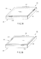
- the arrangement of the antennas 210A, 210B shown in FIGS. 2A and 2B may be changed as shown in FIGS. 3A and 3B.
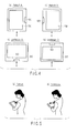
- FIG. 4 is views for explaining the kinds of an image display style under the tablet mode.
- FIG. 5 is views for explaining a difference in usage style corresponding to the kind of the image display style.
- the image display style is classified largely to "portrait” (vertically long) and “landscape” (laterally long).
- FIG. 5 (a) shows an example in which user uses the tablet PC 100 in the portrait style.
- FIG. 5 (b) shows an example in which a user uses the tablet PC 100 in the landscape style.
- FIG. 6 is a block diagram showing an example of the system configuration of the tablet PC 100.
- the main body 300 of the tablet PC 100 includes a CPU 111, a north bridge 112, a main memory 113, a graphics controller 114, and a south bridge 115.
- the main body 300 further includes a BIOS-ROM 120, a hard disk drive (HDD) 130, an optical disk drive (ODD) 140, a LAN controller 151, wireless LAN controllers 310A, 310B, a card controller 153, an embedded controller/keyboard controller IC (EC/KBC) 160, and a power circuit 170.
- the CPU 111 is a processor for controlling the operation of the computer 10.
- the CPU 111 executes an operating system (OS) which is loaded from a boot device, for example, the HDD 130 to the main memory 113.
- the CPU 111 executes a variety of application programs.
- the CPU 111 executes a system basic input output system (BIOS) stored in the BIOS-ROM 120.
- BIOS is a program for executing hardware control and the like.
- the north bridge 112 is a bridge device for connecting between the local bus of the CPU 111 and the south bridge 115.
- the north bridge 112 incorporates a memory controller for access-controlling the main memory 113. Further, the north bridge 112 has a function of executing communication with the graphics controller 114 through an accelerated graphics port (AGP).
- AGP accelerated graphics port
- the graphics controller 114 is a display controller for controlling the LCD 230 and the like.
- the graphic controller 114 has a video memory (VRAM) 114a, which generates a video signal for forming a display image to be displayed on the LCD 230 from display data written in the VRAM 114a.
- VRAM video memory
- the south bridge 115 controls access to the BIOS-ROM 120.
- the BIOS-ROM 120 is a nonvolatile memory rewritable like the flash ROM.
- the BIOS-ROM 120 stores a system BIOS.
- the south bridge 115 controls a disk drive (I/O device) such as the HDD 130 and ODD 140.
- the south bridge 115 is connected to a peripheral component interconnect (PCI) bus 2 and a low pin count (LPC) bus 3.
- PCI peripheral component interconnect
- LPC low pin count
- the south bridge 115 controls each device on the PCI bus 2 and LPC bus 3.
- the PCI bus 2 is used as a system bus.
- the HDD 130 is a storage device for storing a variety of software and data.
- the HDD 130 writes/reads data with a head (magnetic head) to/from a magnetic recording medium (magnetic disk) rotated by a motor.
- An operating system (OS) is stored preliminarily in the HDD 130.
- the OS is loaded to the main memory 113 according to the system BIOS stored in the BIOS-ROM 120 and executed by the CPU 111.
- the ODD 140 is a drive unit for rotating an optical recording medium (optical disk) such as a compact disk (CD) and a digital versatile disk (DVD) with a motor.
- the ODD 140 reads/writes data from/to an optical disk with a head (optical head).
- the LAN controller 151, the wireless LAN controllers 310A, 310B and the card controller 153 are connected to the PCI bus 2.
- the LAN controller 151 is a network controller for connecting the main body 300 to LAN (wired LAN).
- the wireless LAN controller 310A is a network controller for connecting the main body 300 to the wireless LAN.
- the card controller 153 controls a card device such as a PC card and a secure digital (SD) card inserted into a card slot connected to the card controller 153.
- SD secure digital
- the EC/KBC 160 is a microcomputer in which the embedded controller for power control and the keyboard controller for controlling the keyboard (KB) 13 and a touch pad 16 are integrated on a single chip.
- the EC/KBC 160 has a power control function which operates in cooperation with the power circuit 170 and turns ON the power of the computer 10 answering a user's operating of the power button switch 14.
- the EC/KBC 160 can notify the BIOS, driver or OS of information indicating various kinds of conditions by receiving each detection signal sent from an acceleration sensor 15 or a hinge state sensor 11.
- the acceleration sensor 15 detects an acceleration given from outside relating to triaxial direction in space.
- the hinge state sensor 11 detects the state of the hinge 120 (that is, state of the display unit 200 relative to the main body 300).
- the power circuit 170 generates a system power voltage to be applied to each element of the main body 300 using DC power supplied from a rechargeable battery 171 or through an AC adaptor 172 as a high voltage power source.
- the AC adaptor 172 converts AC power to DC power.
- FIG. 7 is a block diagram showing an example of the configuration common to the wireless LAN controllers 310A, 310B. Here, only the wireless LAN controller 310A will be described.
- the wireless LAN controller 310A comprises a radio frequency (RF) section 311, a crystal oscillation section 312, and a base band processing section 313.
- RF radio frequency
- the RF unit 311 converts a high frequency signal inputted from the antenna 210A through the power cable 220A to a low frequency signal based on an oscillation frequency of the crystal oscillation section 312 and outputs to the base band processing section 313. Further, a base band signal outputted from the base band processing section 313 is converted to a high frequency signal based on an oscillation frequency from the crystal oscillation section 312 and outputted to the antenna 210A through the power cable 220A.
- the base band processing section 313 executes analog/digital conversion on the base band signal outputted from the RF unit 311 to change it to a digital signal which the CPU 111 can process and outputs the digital signal to the bus 2. Further, it executes digital/analog conversion on a digital signal inputted from the bus 2 to change it to a base band analog signal and outputs the base band analog signal to the RF unit 311.
- FIG. 8 is a block diagram showing an example of the functional configuration relating to inhibitory control of an electromagnetic wave radiated from a transmitting/receiving antenna.
- the EC 400 can transmit information of acceleration obtained from the acceleration sensor 15 and information of the hinge state sent from the hinge state sensor 11 to the OS 403 through the BIOS 401 or the like. In the meantime, this information may be so constructed that these pieces of information are sent to the OS 403 not through the EC 400.
- the BIOS 401 can acquire information of acceleration and information of hinge state and notify those to the OS 403.
- the driver 402 requests the EC 400 to stop/restart supply of power to the wireless LAN controller 310A through the BIOS 401 if an instruction about stop/restart of transmission output is dispatched from the OS 403.
- the driver 402 can decrease/increase the transmission output of the wireless LAN controller 310A.
- the output of amplification of the RF unit 331 of the wireless LAN controller 310A changes so that radiation of the electromagnetic wave from the antenna 210A may be suppressed or the suppression may be released.
- the OS 403 can recognize the usage style (tablet mode, lap top mode or the like) of the tablet PC based on information of the hinge state obtained from the BIOS 40 or recognize the direction of a currently displayed image based on possessed information about display. Further, the OS 403 can recognize the motion of the tablet PC based on acquired information about acceleration and select the direction of a displayed image appropriately (that is, any one of the display styles shown in FIG. 4 can be selected).
- the OS 403 can acquire carrier information (information about provider or the like) through a predetermined communication module (3G module and the like). The information is transferred to a utility 404 and used to determine whether or not suppression (stop or reduction) of the transmission output of the wireless LAN controller 310A is required.
- the utility 404 includes various functions such as a state recognition section 501, a transmission output control section 502 and a suppression necessity determining section 503 as shown in FIG. 9. In the meantime, these functions do not need to be provided on the utility 404, and part of the functions may be borne by other software or hardware.
- the state recognition section 501 can determine whether or not a predetermined state in which the tablet mode is formed, and the antenna 210A is located in a downward direction of an image displayed on the LCD 230 based on information of the hinge condition obtained from the BIOS 401 (or OS 403) and information about the direction of a display image obtained from the OS 403 or recognize this state.
- the antenna being located in a "downward direction" of an image means that the antenna is located between the user and the display section situated at the front face of the display unit.
- the transmission output control section 502 can execute control (for example, control for reducing the amount of radiation, control for stopping the radiation, control for stopping transmission of the signal from the wireless LAN controller 310A to the antenna 210A) for suppressing radiation of the electromagnetic wave from the antenna 210A, when the above predetermined state is recognized.
- control for example, control for reducing the amount of radiation, control for stopping the radiation, control for stopping transmission of the signal from the wireless LAN controller 310A to the antenna 210A
- the suppression necessity determining section 503 can determine whether or not suppression (stop or reduction) of the transmission output of the wireless LAN controller 310A is required by recognizing whether or not a provider indicated in acquired carrier information is mentioned in a predetermined list.
- the system may be constructed such that whether or not the control of the transmission output control section 502 is executed based on this determination result.
- the utility 404 acquires information of the hinge state from the BIOS 401 (or OS 403) and at the same time acquires information about the direction of a displayed image (block S11). Based on such information, the utility 404 determines whether or not the tablet mode is formed and the predetermined state in which the antenna 210A is located in the downward direction of an image displayed on the LCD 230 is established, namely below the display section of the display unit 200 (block S12). Unless the predetermined state is established (NO in block S13), the output of the antenna 210A is kept at a normal output (for example, maximum output) (or returned to the normal output) (block S14), and the processing from block S11 is repeated.
- a normal output for example, maximum output
- the predetermined condition is established (YES in block S13)
- the normal output for example, maximum output
- control for reducing or stopping the output of the antenna 210A is executed to satisfy a standard specified by a law relating to electromagnetic waves (block S17), and the processing from block S11 is repeated.
- the electromagnetic wave in case of the tablet PC on which the antenna for radiating the electromagnetic wave has been mounted, the electromagnetic wave can be properly controlled to reduce a risk of influence on human body if the antenna approaches user's body (for example, stomach). Further, even if the direction of image display changes as the tablet PC moves, the inhibitory control of the radiated electromagnetic wave can be executed appropriately. Additionally, it is possible to determined whether or not the inhibitory control of the radiated electromagnetic wave is executed depending on the provider.
Landscapes
- Engineering & Computer Science (AREA)
- Computer Hardware Design (AREA)
- Theoretical Computer Science (AREA)
- Physics & Mathematics (AREA)
- General Engineering & Computer Science (AREA)
- General Physics & Mathematics (AREA)
- Human Computer Interaction (AREA)
- Computer Networks & Wireless Communication (AREA)
- Mathematical Physics (AREA)
- Controls And Circuits For Display Device (AREA)
- User Interface Of Digital Computer (AREA)
- Variable-Direction Aerials And Aerial Arrays (AREA)
- Support Of Aerials (AREA)
- Transceivers (AREA)
Abstract
According to one embodiment, an information processing apparatus (100) includes a display unit (200) on which an antenna (210A) is mounted, an LCD (230) provided on the display unit (200), and a controller which controls the amount of radiation of an electromagnetic wave from the antenna (210A), when the antenna (210A) is located in a downward direction of an image displayed on the LCD (230).

Description
- Embodiments of the present invention relate to an information apparatus having a display unit on which an antenna for radiating an electromagnetic wave and an operation control method thereof.
- Some types of information apparatus, such as a personal computer for example, include an antenna mounted on its display unit in order to radio-communicate with another apparatus. For example,
U.S. Pat. No. 6,426,723 describes an example of a laptop computer having antennas mounted on the top portion and side portion of a display unit thereof. - In recent years, an information apparatus referred to as a "tablet PC" in which a display unit having a tablet on its display section is rotatably mounted on the main body through a hinge, has gained more public acceptance. Generally, this kind of information apparatus achieves a tablet usage condition called tablet mode by matching the back face of the display unit with the top face of the main body such that the tablet face is directed upward.
- When a tablet PC on which an antenna for radiating an electromagnetic wave has been mounted is used, particularly when the tablet PC is used in the tablet usage condition, the antenna may be located near the user's body (such as the stomach). Since it is said that the electromagnetic wave may have an influence on a human body, there is a standard specified by law relating to electromagnetic waves.
- It is an object of the present invention to provide an information apparatus and operation control method thereof which can satisfy the rule stipulated by the law relating to electric waves.
- According to one embodiment, an information processing apparatus includes a display unit on which an antenna is mounted, a display section provided on the display unit, and control means (111, 404) for controlling an amount of radiation of an electromagnetic wave from the antenna when the antenna is located in a downward direction of an image displayed on the display section so that the antenna is located between a user and the display section displaying the image.
- The invention can be more fully understood from the following detailed description when taken in conjunction with the accompanying drawings, in which:
- FIG. 1 is an exemplary perspective view showing the appearance of an information apparatus according to an embodiment of the present invention;
- FIG. 2A is an exemplary view showing a state in which a display unit is closed to the main body side;
- FIG. 2B is an exemplary view showing a state in which a display unit is closed to the side of a main body with a liquid crystal panel facing outward;
- FIG. 3A is an exemplary view showing a modification of antenna arrangement of FIG. 2A;
- FIG. 3B is an exemplary view showing a modification of antenna arrangement of FIG. 2B;
- FIG. 4 is views for explaining the kinds of image display styles in a tablet mode;
- FIG. 5 is views for explaining a difference of the usage style depending on the kind of the image display style;
- FIG. 6 is an exemplary block diagram showing an example of the system configuration of a tablet PC;
- FIG. 7 is an exemplary block diagram showing an example of the configuration of a wireless LAN controller;
- FIG. 8 is an exemplary block diagram showing an example of the functional configuration relating to inhibitory control of an electromagnetic wave radiated from a transmitting/receiving antenna;
- FIG. 9 is an exemplary block diagram showing an example of the functional configuration of utility; and
- FIG. 10 is an exemplary flow chart showing an example of an operation relating to the inhibitory control of the electromagnetic wave radiated from the transmitting/receiving antenna.
- Hereinafter, embodiments of the present invention will be described with reference to the drawings.
- FIG. 1 is a perspective view showing an appearance of an information apparatus according to one embodiment of the present invention.
- The information apparatus shown in FIG. 1 is a personal computer called tablet PC. The tablet PC 200 has a structure in which a
display unit 200 having a tablet on a liquid crystal panel (display section) 230 is rotatably mounted to the main body through ahinge 120. The structure allows thedisplay unit 200 to rotate freely around thehinge 120, so that thedisplay unit 200 can be closed to themain body 300 with the liquid crystal panel (LCD) 230 facing outward. FIG. 1 shows a state in which thedisplay unit 200 is opened from themain body 300 with theLCD 230 facing inward (corresponding to lap top usage condition called "lap top mode" (or "ordinary mode"). - The
display unit 200 includesantennas antennas antenna 210A is provided on the top of the surface of thedisplay unit 200 in a state in which thedisplay unit 200 is opened and on the other hand, theantenna 210B is provided on the side face of thedisplay unit 200. Theantenna 210A is provided on the front face (side of the LCD 230) of thedisplay unit 200, and theantenna 210B is provided on the back face of thedisplay unit 200. Of course, theantenna 210A may be provided on the back of thedisplay unit 200, and theantenna 210B may be provided on the front face of thedisplay unit 200. Of theantennas antenna 210A is a transmitting/receiving antenna which radiates an electromagnetic wave. - On the other hand, the
main body 300 includes wireless LAN controllers (modules) 310A, 310B. Apower cable 220A is extended from theantenna 210A so as to pass near the left side of thedisplay unit 200, and is connected to thewireless LAN controller 310A through ahinge 120. Likewise, thepower cable 220B is extended downward from theantenna 210B and connected to thewireless LAN controller 310B through thehinge 120. - FIG. 2A shows a state in which the
display unit 200 is closed to the side of themain body 300 with theLCD 230 facing inward. Representation of thepower cables display unit 200 is closed to the side of themain body 300 with theLCD 230 facing outward, that is, such that the back face opposing the front face of thedisplay unit 200 opposes the top face of the main body 300 (corresponding to a tablet use style called "tablet mode"). Representation of thepower cables - The arrangement of the
antennas - FIG. 4 is views for explaining the kinds of an image display style under the tablet mode. FIG. 5 is views for explaining a difference in usage style corresponding to the kind of the image display style.
- As shown in FIG. 4, four kinds of the image display styles can be considered depending the direction of an image displayed on the
LCD 230 under the tablet mode. The image display style is classified largely to "portrait" (vertically long) and "landscape" (laterally long). - In the example of the portrait A shown in FIG. 4 (a), the
hinge 120 is located at the right side. On the other hand, in the example of the portrait B shown in FIG. 4 (b), thehinge 120 is located at the left side. FIG. 5 (a) shows an example in which user uses the tablet PC 100 in the portrait style. - In the example of the landscape A shown in FIG. 4 (c), the
hinge 120 is located on the bottom. On the other hand, in the example of the landscape B shown in FIG. 4 (d), thehinge 120 is located on the top. FIG. 5 (b) shows an example in which a user uses the tablet PC 100 in the landscape style. - FIG. 6 is a block diagram showing an example of the system configuration of the tablet PC 100.
- The
main body 300 of thetablet PC 100 includes aCPU 111, anorth bridge 112, amain memory 113, agraphics controller 114, and asouth bridge 115. Themain body 300 further includes a BIOS-ROM 120, a hard disk drive (HDD) 130, an optical disk drive (ODD) 140, aLAN controller 151,wireless LAN controllers card controller 153, an embedded controller/keyboard controller IC (EC/KBC) 160, and apower circuit 170. - The
CPU 111 is a processor for controlling the operation of the computer 10. TheCPU 111 executes an operating system (OS) which is loaded from a boot device, for example, theHDD 130 to themain memory 113. TheCPU 111 executes a variety of application programs. TheCPU 111 executes a system basic input output system (BIOS) stored in the BIOS-ROM 120. The system BIOS is a program for executing hardware control and the like. - The
north bridge 112 is a bridge device for connecting between the local bus of theCPU 111 and thesouth bridge 115. Thenorth bridge 112 incorporates a memory controller for access-controlling themain memory 113. Further, thenorth bridge 112 has a function of executing communication with thegraphics controller 114 through an accelerated graphics port (AGP). - The
graphics controller 114 is a display controller for controlling theLCD 230 and the like. Thegraphic controller 114 has a video memory (VRAM) 114a, which generates a video signal for forming a display image to be displayed on theLCD 230 from display data written in theVRAM 114a. - The
south bridge 115 controls access to the BIOS-ROM 120. The BIOS-ROM 120 is a nonvolatile memory rewritable like the flash ROM. The BIOS-ROM 120 stores a system BIOS. Thesouth bridge 115 controls a disk drive (I/O device) such as theHDD 130 andODD 140. - The
south bridge 115 is connected to a peripheral component interconnect (PCI)bus 2 and a low pin count (LPC)bus 3. Thesouth bridge 115 controls each device on thePCI bus 2 andLPC bus 3. ThePCI bus 2 is used as a system bus. - The
HDD 130 is a storage device for storing a variety of software and data. TheHDD 130 writes/reads data with a head (magnetic head) to/from a magnetic recording medium (magnetic disk) rotated by a motor. An operating system (OS) is stored preliminarily in theHDD 130. The OS is loaded to themain memory 113 according to the system BIOS stored in the BIOS-ROM 120 and executed by theCPU 111. - The
ODD 140 is a drive unit for rotating an optical recording medium (optical disk) such as a compact disk (CD) and a digital versatile disk (DVD) with a motor. TheODD 140 reads/writes data from/to an optical disk with a head (optical head). - The
LAN controller 151, thewireless LAN controllers card controller 153 are connected to thePCI bus 2. TheLAN controller 151 is a network controller for connecting themain body 300 to LAN (wired LAN). Thewireless LAN controller 310A is a network controller for connecting themain body 300 to the wireless LAN. Thecard controller 153 controls a card device such as a PC card and a secure digital (SD) card inserted into a card slot connected to thecard controller 153. - The EC/
KBC 160 is a microcomputer in which the embedded controller for power control and the keyboard controller for controlling the keyboard (KB) 13 and atouch pad 16 are integrated on a single chip. The EC/KBC 160 has a power control function which operates in cooperation with thepower circuit 170 and turns ON the power of the computer 10 answering a user's operating of thepower button switch 14. The EC/KBC 160 can notify the BIOS, driver or OS of information indicating various kinds of conditions by receiving each detection signal sent from anacceleration sensor 15 or ahinge state sensor 11. - The
acceleration sensor 15 detects an acceleration given from outside relating to triaxial direction in space. Thehinge state sensor 11 detects the state of the hinge 120 (that is, state of thedisplay unit 200 relative to the main body 300). - The
power circuit 170 generates a system power voltage to be applied to each element of themain body 300 using DC power supplied from arechargeable battery 171 or through anAC adaptor 172 as a high voltage power source. TheAC adaptor 172 converts AC power to DC power. - FIG. 7 is a block diagram showing an example of the configuration common to the
wireless LAN controllers wireless LAN controller 310A will be described. - The
wireless LAN controller 310A comprises a radio frequency (RF)section 311, acrystal oscillation section 312, and a baseband processing section 313. - The
RF unit 311 converts a high frequency signal inputted from theantenna 210A through thepower cable 220A to a low frequency signal based on an oscillation frequency of thecrystal oscillation section 312 and outputs to the baseband processing section 313. Further, a base band signal outputted from the baseband processing section 313 is converted to a high frequency signal based on an oscillation frequency from thecrystal oscillation section 312 and outputted to theantenna 210A through thepower cable 220A. - The base
band processing section 313 executes analog/digital conversion on the base band signal outputted from theRF unit 311 to change it to a digital signal which theCPU 111 can process and outputs the digital signal to thebus 2. Further, it executes digital/analog conversion on a digital signal inputted from thebus 2 to change it to a base band analog signal and outputs the base band analog signal to theRF unit 311. - FIG. 8 is a block diagram showing an example of the functional configuration relating to inhibitory control of an electromagnetic wave radiated from a transmitting/receiving antenna.
- The
EC 400 can transmit information of acceleration obtained from theacceleration sensor 15 and information of the hinge state sent from thehinge state sensor 11 to theOS 403 through theBIOS 401 or the like. In the meantime, this information may be so constructed that these pieces of information are sent to theOS 403 not through theEC 400. - The
BIOS 401 can acquire information of acceleration and information of hinge state and notify those to theOS 403. - The
driver 402 requests theEC 400 to stop/restart supply of power to thewireless LAN controller 310A through theBIOS 401 if an instruction about stop/restart of transmission output is dispatched from theOS 403. When an instruction about reduction/increase of the transmission output is dispatched from theOS 403, thedriver 402 can decrease/increase the transmission output of thewireless LAN controller 310A. As a consequence, the output of amplification of the RF unit 331 of thewireless LAN controller 310A changes so that radiation of the electromagnetic wave from theantenna 210A may be suppressed or the suppression may be released. - The
OS 403 can recognize the usage style (tablet mode, lap top mode or the like) of the tablet PC based on information of the hinge state obtained from the BIOS 40 or recognize the direction of a currently displayed image based on possessed information about display. Further, theOS 403 can recognize the motion of the tablet PC based on acquired information about acceleration and select the direction of a displayed image appropriately (that is, any one of the display styles shown in FIG. 4 can be selected). TheOS 403 can acquire carrier information (information about provider or the like) through a predetermined communication module (3G module and the like). The information is transferred to autility 404 and used to determine whether or not suppression (stop or reduction) of the transmission output of thewireless LAN controller 310A is required. - The
utility 404 includes various functions such as astate recognition section 501, a transmissionoutput control section 502 and a suppressionnecessity determining section 503 as shown in FIG. 9. In the meantime, these functions do not need to be provided on theutility 404, and part of the functions may be borne by other software or hardware. - The
state recognition section 501 can determine whether or not a predetermined state in which the tablet mode is formed, and theantenna 210A is located in a downward direction of an image displayed on theLCD 230 based on information of the hinge condition obtained from the BIOS 401 (or OS 403) and information about the direction of a display image obtained from theOS 403 or recognize this state. The antenna being located in a "downward direction" of an image means that the antenna is located between the user and the display section situated at the front face of the display unit. - The transmission
output control section 502 can execute control (for example, control for reducing the amount of radiation, control for stopping the radiation, control for stopping transmission of the signal from thewireless LAN controller 310A to theantenna 210A) for suppressing radiation of the electromagnetic wave from theantenna 210A, when the above predetermined state is recognized. - The suppression
necessity determining section 503 can determine whether or not suppression (stop or reduction) of the transmission output of thewireless LAN controller 310A is required by recognizing whether or not a provider indicated in acquired carrier information is mentioned in a predetermined list. The system may be constructed such that whether or not the control of the transmissionoutput control section 502 is executed based on this determination result. - Next, an example of an operation related to inhibitory control of the electromagnetic wave radiated from the transmitting/receiving antenna will be described with reference to FIG. 10.
- The
utility 404 acquires information of the hinge state from the BIOS 401 (or OS 403) and at the same time acquires information about the direction of a displayed image (block S11). Based on such information, theutility 404 determines whether or not the tablet mode is formed and the predetermined state in which theantenna 210A is located in the downward direction of an image displayed on theLCD 230 is established, namely below the display section of the display unit 200 (block S12). Unless the predetermined state is established (NO in block S13), the output of theantenna 210A is kept at a normal output (for example, maximum output) (or returned to the normal output) (block S14), and the processing from block S11 is repeated. On the other hand, if the predetermined condition is established (YES in block S13), it is confirmed whether or not the provider indicated in the acquired carrier information is mentioned in the predetermined list, whereby it is determined whether or not the suppression (stop or reduction) of the transmission output of thewireless LAN controller 310A is required (block S15). If the suppression is not required (NO in block S16), the output of theantenna 210A is kept at the normal output (for example, maximum output) (or returned to the normal output) (block S14), and the processing from block S11 is repeated. On the other hand, if the suppression is required (YES in block S16), control for reducing or stopping the output of theantenna 210A is executed to satisfy a standard specified by a law relating to electromagnetic waves (block S17), and the processing from block S11 is repeated. - According to this embodiment, in case of the tablet PC on which the antenna for radiating the electromagnetic wave has been mounted, the electromagnetic wave can be properly controlled to reduce a risk of influence on human body if the antenna approaches user's body (for example, stomach). Further, even if the direction of image display changes as the tablet PC moves, the inhibitory control of the radiated electromagnetic wave can be executed appropriately. Additionally, it is possible to determined whether or not the inhibitory control of the radiated electromagnetic wave is executed depending on the provider.
Claims (20)
- An information processing apparatus characterized by comprising:a display unit (200) on which an antenna (210A) is mounted;a display section (230) provided on the display unit (200); andcontrol means (111, 404) for controlling an amount of radiation of an electromagnetic wave from the antenna (210A) when the antenna (210A) is located in a downward direction of an image displayed on the display section (230) so that the antenna (210A) is located between a user and the display section (230) displaying the image.
- An information processing apparatus according to claim 1, characterized in that, when the antenna (210A) is located in the downward direction, the control means (111, 404) stops radiation of the electromagnetic wave from the antenna (210A).
- An information processing apparatus according to claim 1, characterized in that, when the antenna (210A) is located in the downward direction, the control means (111, 404) reduces the amount of radiation of the electromagnetic wave from the antenna (210A).
- An information processing apparatus according to claim 1, characterized by further comprising:a radio module (310A) to transmit a signal to the antenna (210A), whereinthe control means (111, 404) includes means for stopping transmission of the signal from the radio module (310A) to the antenna (210A).
- An information processing apparatus according to claim 1, characterized by further comprising:an acceleration sensor (15) to detect an acceleration; andswitching means (111, 403) for switching the direction of an image displayed on the display section (230) based on the acceleration detected by the acceleration sensor (15), whereinwhen the antenna (210A) is located in a downward direction of the image switched by the switching means (111, 403), the control means (111, 404) controls the amount of radiation of the electromagnetic wave from the antenna (210A).
- An information processing apparatus according to claim 1, characterized by further comprising:determining means (111, 403) for determining whether or not control by the control means (111, 404) is carried out according to information of a provider who transmits an electromagnetic wave to be received by the antenna (210A).
- An information processing apparatus characterized by comprising:a display unit (200) on which an antenna (210A) that radiates an electromagnetic wave is mounted;a display section (230) provided on a front face of the display unit (200);a main (300) rotatably mounted to the display unit (200) through a hinge; andcontrol means (111, 404) for controlling an amount of radiation of the electromagnetic wave from the antenna (210A) when the antenna (210A) is located in a downward direction from an image displayed on the display section (230).
- An information processing apparatus according to claim 7, characterized in that the control means (111, 404) controls the amount of radiation of the electromagnetic wave from the antenna (210A) when a back face opposing the front face of the display unit (200) is located to oppose the top face of the main body (300) while the antenna (210A) is located in the downward direction of the image displayed on the display section (230).
- An information processing apparatus according to claim 7, characterized in that the antenna (210A) is disposed at the other side of the display unit (200) to which the hinge is coupled.
- An information processing apparatus according to claim 7, characterized in that, when the antenna (210A) is located in the downward direction of the image displayed on the display section (230), the control means (111, 404) stops radiation of the electromagnetic wave from the antenna (210A).
- An information processing apparatus according to claim 7, characterized in that, when the antenna (210A) is located in the downward direction of the image displayed on the display section (230), the control means (111, 404) reduces the amount of radiation of the electromagnetic wave from the antenna (210A).
- An information processing apparatus according to claim 7, characterized by further comprising:a radio module (310A) to transmit a signal to the antenna (210A), whereinthe control means (111, 404) includes means for stopping transmission of the signal from the radio module (310A) to the antenna (210A).
- An information processing apparatus according to claim 7, characterized in that the control means (111, 404) controls the amount of radiation of the electromagnetic wave from the antenna (210A) when the antenna (210A) is located in the downward direction of the image displayed on the display section (230) that occurs when the antenna (210A) is situated between the display section (230) of the display unit (200) and an user while the information processing apparatus is in use.
- An information processing apparatus according to claim 7, characterized by further comprising:an acceleration sensor (15) to detect a tri-axial direction of the information processing apparatus in space; andswitching means (111, 403) for switching a direction of the image displayed on the display section (230) based on information from the acceleration sensor (15), whereinthe control means (111, 404) controls the amount of radiation of the electromagnetic wave from the antenna (210A) based on information from the acceleration sensor (15).
- An operation control method of an information processing apparatus in which a display section is provided on a display unit on which an antenna is mounted, the method characterized by comprising:determining whether or not the antenna is located in a downward direction from an image displayed on the display section when the information processing apparatus is in use (S11 to S12); andwhen it is determined that the antenna is located in the downward direction from the image displayed on the display section, controlling the amount of radiation of an electromagnetic wave from the antenna (S13 to S17).
- An operation control method according to claim 15, characterized in that the radiation of an electromagnetic wave from the antenna is controlled to be stopped (S17).
- An operation control method according to claim 15, characterized in that the amount of radiation of an electromagnetic wave from the antenna is controlled to be reduced from a previous amount of radiation (S17).
- An operation control method according to claim 15, characterized in that the amount of radiation of an electromagnetic wave from the antenna is controlled by stopping transmission of a signal from a radio module included in the information processing apparatus to the antenna (S17).
- An operation control method according to claim 15, characterized by further comprising:detecting an acceleration by an acceleration sensor included in the information processing apparatus (S11); andswitching a direction of an image displayed on the display section based on the acceleration detected by the acceleration sensor.
- An operation control method according to claim 15, characterized by further comprising:determining whether or not the control for the amount of radiation of an electromagnetic wave from the antenna is carried out according to information of a provider who transmits an electromagnetic wave to be received by the antenna (S15).
Applications Claiming Priority (1)
| Application Number | Priority Date | Filing Date | Title |
|---|---|---|---|
| JP2006052043A JP4185104B2 (en) | 2006-02-28 | 2006-02-28 | Information device and operation control method thereof |
Publications (1)
| Publication Number | Publication Date |
|---|---|
| EP1826654A2 true EP1826654A2 (en) | 2007-08-29 |
Family
ID=37772602
Family Applications (1)
| Application Number | Title | Priority Date | Filing Date |
|---|---|---|---|
| EP06122038A Withdrawn EP1826654A2 (en) | 2006-02-28 | 2006-10-10 | Information processing apparatus and operation control method thereof |
Country Status (4)
| Country | Link |
|---|---|
| US (1) | US7733275B2 (en) |
| EP (1) | EP1826654A2 (en) |
| JP (1) | JP4185104B2 (en) |
| CN (1) | CN100517282C (en) |
Families Citing this family (25)
| Publication number | Priority date | Publication date | Assignee | Title |
|---|---|---|---|---|
| US7193562B2 (en) | 2004-11-22 | 2007-03-20 | Ruckus Wireless, Inc. | Circuit board having a peripheral antenna apparatus with selectable antenna elements |
| US7292198B2 (en) | 2004-08-18 | 2007-11-06 | Ruckus Wireless, Inc. | System and method for an omnidirectional planar antenna apparatus with selectable elements |
| US7358912B1 (en) | 2005-06-24 | 2008-04-15 | Ruckus Wireless, Inc. | Coverage antenna apparatus with selectable horizontal and vertical polarization elements |
| US7893882B2 (en) | 2007-01-08 | 2011-02-22 | Ruckus Wireless, Inc. | Pattern shaping of RF emission patterns |
| JP2009152705A (en) * | 2007-12-19 | 2009-07-09 | Toshiba Corp | Electronic computer and switching circuit |
| JP2009296377A (en) * | 2008-06-05 | 2009-12-17 | Toshiba Corp | Electronic apparatus |
| US20110115735A1 (en) * | 2008-07-07 | 2011-05-19 | Lev Jeffrey A | Tablet Computers Having An Internal Antenna |
| JP2010067225A (en) * | 2008-09-12 | 2010-03-25 | Toshiba Corp | Information processor |
| US8217843B2 (en) * | 2009-03-13 | 2012-07-10 | Ruckus Wireless, Inc. | Adjustment of radiation patterns utilizing a position sensor |
| WO2011048747A1 (en) * | 2009-10-19 | 2011-04-28 | 日本電気株式会社 | Wireless communication device |
| JP2011091744A (en) * | 2009-10-26 | 2011-05-06 | Alps Electric Co Ltd | Information processing apparatus |
| JP4810601B2 (en) * | 2009-11-30 | 2011-11-09 | 株式会社東芝 | Information processing apparatus and control method |
| JP5283762B2 (en) * | 2009-12-14 | 2013-09-04 | 富士通株式会社 | Arithmetic processing apparatus, information processing apparatus and control method thereof |
| KR101304321B1 (en) | 2010-01-22 | 2013-09-11 | 전자부품연구원 | Method for providing UI according to single touch pressure and electronic device using the same |
| JP2011171935A (en) | 2010-02-17 | 2011-09-01 | Panasonic Corp | Communication equipment |
| JP5664443B2 (en) * | 2011-04-28 | 2015-02-04 | 富士通株式会社 | Information processing apparatus, radio wave intensity control method, and program |
| US8756668B2 (en) | 2012-02-09 | 2014-06-17 | Ruckus Wireless, Inc. | Dynamic PSK for hotspots |
| US10186750B2 (en) | 2012-02-14 | 2019-01-22 | Arris Enterprises Llc | Radio frequency antenna array with spacing element |
| US9634403B2 (en) | 2012-02-14 | 2017-04-25 | Ruckus Wireless, Inc. | Radio frequency emission pattern shaping |
| US9092610B2 (en) | 2012-04-04 | 2015-07-28 | Ruckus Wireless, Inc. | Key assignment for a brand |
| US9007179B2 (en) * | 2013-03-25 | 2015-04-14 | Panasonic Intellectual Property Management Co., Ltd. | Electronic apparatus |
| US20150171504A1 (en) * | 2013-12-13 | 2015-06-18 | Kabushiki Kaisha Toshiba | Electronic apparatus |
| CN105305017A (en) * | 2014-06-26 | 2016-02-03 | 展讯通信(上海)有限公司 | Mobile terminal |
| TWI648657B (en) * | 2017-10-23 | 2019-01-21 | 群光電子股份有限公司 | Keyboard device and system operation method |
| JP2021026546A (en) * | 2019-08-06 | 2021-02-22 | パナソニックIpマネジメント株式会社 | Convertible type notebook computer |
Family Cites Families (15)
| Publication number | Priority date | Publication date | Assignee | Title |
|---|---|---|---|---|
| JPH11186841A (en) | 1997-12-22 | 1999-07-09 | Matsushita Electric Ind Co Ltd | Transmission device and transmission method thereof |
| JPH11340845A (en) | 1998-05-28 | 1999-12-10 | Kokusai Electric Co Ltd | Portable wireless telephone |
| US6426723B1 (en) * | 2001-01-19 | 2002-07-30 | Nortel Networks Limited | Antenna arrangement for multiple input multiple output communications systems |
| JP2002261665A (en) | 2001-02-28 | 2002-09-13 | Matsushita Electric Ind Co Ltd | Portable wireless devices |
| JP2003101623A (en) | 2001-09-21 | 2003-04-04 | Kyocera Corp | Foldable portable radio |
| JP3891831B2 (en) | 2001-11-26 | 2007-03-14 | シャープ株式会社 | Portable radio |
| JP3875646B2 (en) | 2003-02-26 | 2007-01-31 | 日本航空電子工業株式会社 | 4-split key-top switch, input device, mobile phone terminal using this |
| JP4168261B2 (en) | 2003-03-11 | 2008-10-22 | 日本電気株式会社 | Mobile phone antenna and switching method thereof |
| EP1912279B1 (en) * | 2003-06-12 | 2011-01-05 | Research In Motion Limited | Multiple-element antenna with electromagnetically coupled floating antenna element |
| JP2005072734A (en) | 2003-08-20 | 2005-03-17 | Nec Corp | Camera attached mobile terminal, and image display method and display control program used for the mobile terminal |
| TWM247895U (en) | 2003-12-10 | 2004-10-21 | Tatung Co | Improved frame structure in rotational display |
| JP2005227899A (en) | 2004-02-10 | 2005-08-25 | Vodafone Kk | Information communication terminal |
| US20070146210A1 (en) * | 2004-02-25 | 2007-06-28 | Koninklijke Philips Electronic, N.V. | Antenna array |
| JP2005252539A (en) | 2004-03-03 | 2005-09-15 | Sharp Corp | Mobile device |
| JP4566825B2 (en) * | 2005-06-03 | 2010-10-20 | レノボ・シンガポール・プライベート・リミテッド | Method for controlling antenna of portable terminal device and portable terminal device |
-
2006
- 2006-02-28 JP JP2006052043A patent/JP4185104B2/en not_active Expired - Lifetime
- 2006-09-21 US US11/525,342 patent/US7733275B2/en active Active
- 2006-10-10 EP EP06122038A patent/EP1826654A2/en not_active Withdrawn
- 2006-10-30 CN CNB2006101366896A patent/CN100517282C/en active Active
Also Published As
| Publication number | Publication date |
|---|---|
| US7733275B2 (en) | 2010-06-08 |
| JP2007235329A (en) | 2007-09-13 |
| JP4185104B2 (en) | 2008-11-26 |
| US20070200775A1 (en) | 2007-08-30 |
| CN101030179A (en) | 2007-09-05 |
| CN100517282C (en) | 2009-07-22 |
Similar Documents
| Publication | Publication Date | Title |
|---|---|---|
| US7733275B2 (en) | Information apparatus and operation control method thereof | |
| JP5105767B2 (en) | Information processing apparatus and operation control method thereof | |
| US7852319B2 (en) | Information processing apparatus and operation control method | |
| US7773037B2 (en) | Information processing apparatus, information processing system and radio communication control method | |
| AU2019231476B2 (en) | Electronic device with flexible display and method for operating same | |
| US11456613B2 (en) | Electronic device equipped with flexible display and wireless charging method using the same | |
| CN105610471B (en) | Wireless data input and output method and device | |
| KR102780095B1 (en) | Electronic device and method for controlling electronic device | |
| JP5664443B2 (en) | Information processing apparatus, radio wave intensity control method, and program | |
| US20090160733A1 (en) | Information processing device and display control method | |
| US20090295810A1 (en) | Information processing apparatus | |
| US20090315675A1 (en) | Information Processing Device and Indication Control Method | |
| US9009507B2 (en) | Information processing apparatus and method of controlling the same | |
| US20140092008A1 (en) | Electronic device | |
| JP6810768B2 (en) | Information processing equipment, control methods and programs | |
| JP4267018B2 (en) | Portable computer capable of wireless communication and method of detecting access point | |
| US20110161688A1 (en) | Information processing apparatus | |
| US20130023211A1 (en) | Electronic device and communication state output method | |
| US20070200841A1 (en) | Information processing apparatus and imaging control method | |
| US20070136544A1 (en) | Information processing apparatus and memory control method | |
| US20090167729A1 (en) | Information processing apparatus and panel control method | |
| US20070180284A1 (en) | Electronic device and operation control method | |
| JP6622871B1 (en) | Information processing apparatus and control method | |
| US20100164814A1 (en) | Information processing apparatus | |
| US20080299924A1 (en) | Information processor and control method thereof |
Legal Events
| Date | Code | Title | Description |
|---|---|---|---|
| PUAI | Public reference made under article 153(3) epc to a published international application that has entered the european phase |
Free format text: ORIGINAL CODE: 0009012 |
|
| 17P | Request for examination filed |
Effective date: 20061010 |
|
| AK | Designated contracting states |
Kind code of ref document: A2 Designated state(s): AT BE BG CH CY CZ DE DK EE ES FI FR GB GR HU IE IS IT LI LT LU LV MC NL PL PT RO SE SI SK TR |
|
| AX | Request for extension of the european patent |
Extension state: AL BA HR MK YU |
|
| STAA | Information on the status of an ep patent application or granted ep patent |
Free format text: STATUS: THE APPLICATION HAS BEEN WITHDRAWN |
|
| 18W | Application withdrawn |
Effective date: 20150327 |