EP1826505B1 - Solar collector with concentration - Google Patents
Solar collector with concentration Download PDFInfo
- Publication number
- EP1826505B1 EP1826505B1 EP06075432A EP06075432A EP1826505B1 EP 1826505 B1 EP1826505 B1 EP 1826505B1 EP 06075432 A EP06075432 A EP 06075432A EP 06075432 A EP06075432 A EP 06075432A EP 1826505 B1 EP1826505 B1 EP 1826505B1
- Authority
- EP
- European Patent Office
- Prior art keywords
- solar collector
- heat
- collector according
- concentrating solar
- transformer
- Prior art date
- Legal status (The legal status is an assumption and is not a legal conclusion. Google has not performed a legal analysis and makes no representation as to the accuracy of the status listed.)
- Not-in-force
Links
Images

Classifications
-
- F—MECHANICAL ENGINEERING; LIGHTING; HEATING; WEAPONS; BLASTING
- F24—HEATING; RANGES; VENTILATING
- F24S—SOLAR HEAT COLLECTORS; SOLAR HEAT SYSTEMS
- F24S10/00—Solar heat collectors using working fluids
- F24S10/40—Solar heat collectors using working fluids in absorbing elements surrounded by transparent enclosures, e.g. evacuated solar collectors
- F24S10/45—Solar heat collectors using working fluids in absorbing elements surrounded by transparent enclosures, e.g. evacuated solar collectors the enclosure being cylindrical
-
- F—MECHANICAL ENGINEERING; LIGHTING; HEATING; WEAPONS; BLASTING
- F24—HEATING; RANGES; VENTILATING
- F24S—SOLAR HEAT COLLECTORS; SOLAR HEAT SYSTEMS
- F24S10/00—Solar heat collectors using working fluids
- F24S10/90—Solar heat collectors using working fluids using internal thermosiphonic circulation
- F24S10/95—Solar heat collectors using working fluids using internal thermosiphonic circulation having evaporator sections and condenser sections, e.g. heat pipes
-
- F—MECHANICAL ENGINEERING; LIGHTING; HEATING; WEAPONS; BLASTING
- F24—HEATING; RANGES; VENTILATING
- F24S—SOLAR HEAT COLLECTORS; SOLAR HEAT SYSTEMS
- F24S23/00—Arrangements for concentrating solar-rays for solar heat collectors
- F24S23/70—Arrangements for concentrating solar-rays for solar heat collectors with reflectors
- F24S23/74—Arrangements for concentrating solar-rays for solar heat collectors with reflectors with trough-shaped or cylindro-parabolic reflective surfaces
-
- F—MECHANICAL ENGINEERING; LIGHTING; HEATING; WEAPONS; BLASTING
- F24—HEATING; RANGES; VENTILATING
- F24S—SOLAR HEAT COLLECTORS; SOLAR HEAT SYSTEMS
- F24S80/00—Details, accessories or component parts of solar heat collectors not provided for in groups F24S10/00-F24S70/00
- F24S80/50—Elements for transmitting incoming solar rays and preventing outgoing heat radiation; Transparent coverings
- F24S80/56—Elements for transmitting incoming solar rays and preventing outgoing heat radiation; Transparent coverings characterised by means for preventing heat loss
-
- Y—GENERAL TAGGING OF NEW TECHNOLOGICAL DEVELOPMENTS; GENERAL TAGGING OF CROSS-SECTIONAL TECHNOLOGIES SPANNING OVER SEVERAL SECTIONS OF THE IPC; TECHNICAL SUBJECTS COVERED BY FORMER USPC CROSS-REFERENCE ART COLLECTIONS [XRACs] AND DIGESTS
- Y02—TECHNOLOGIES OR APPLICATIONS FOR MITIGATION OR ADAPTATION AGAINST CLIMATE CHANGE
- Y02E—REDUCTION OF GREENHOUSE GAS [GHG] EMISSIONS, RELATED TO ENERGY GENERATION, TRANSMISSION OR DISTRIBUTION
- Y02E10/00—Energy generation through renewable energy sources
- Y02E10/40—Solar thermal energy, e.g. solar towers
- Y02E10/44—Heat exchange systems
Definitions
- the present invention relates to a concentrated solar collector.
- the general principle of operation of a solar collector is to capture solar radiation to transform it into heat or electricity.
- the sensors using a reflector in the form of a parabola of revolution. These sensors concentrate the sun's rays at the focus of the dish on a Stirling engine, a motor in which heat is transformed into motion, a movement that is itself transformed into electricity by an alternator.
- the converter generally comprises a tube in which circulates a coolant. This fluid will be used to store the heat stored in a storage tank or to return it via a heat exchanger.
- the converter must not only have a high absorption of the entire spectrum of solar radiation, but also have an emissivity, that is to say a reduced heat retransmission. Moreover, in concentrating solar collectors, the surface of the converter is generally smaller than that of the opening of the sensor.
- Such concentrating solar collectors are well known.
- the converters employed have either a rectangular section or a circular section, the reflectors may, for their part, be semi-cylindrical or cyclo-parabolic.
- the documents EP 0 033 054 , US 3,321,012 , and US 4,024,852 describe solar collectors whose converter has a rectangular section.
- the reflector may be in the form of a continuous curve composed of at least 5 circular arcs connecting tangentially to one another, but it may also have a hemicylindrical shape, as described in the document US 3,321,012 , or else be of a cyclo-parabolic form as described in the document US 4,024,852 .
- the documents US 4,059,094 , AT 402,114 and AT 344,375 describe solar collectors whose converter has a circular section.
- the reflector may have a hemicylindrical shape, or even a cyclo-parabolic form as described in document US 4 059094 .
- the present invention aims to provide a concentrated solar collector which does not have the drawbacks of the state of the art.
- it aims to provide a concentrated solar collector with improved efficiency. It also aims to provide a solar collector that can be used in the form of solar panels, and which can, in addition, be used for the production of electricity, heating, air conditioning or for desalination of water.
- the present invention discloses a concentrating solar collector comprising a transparent sunlight cover, a section reflector cylindro-parabolic, a heat transfer element and a transformer for reducing energy losses emissivity, said transformer not being in contact with said heat transfer element.
- the present invention further discloses the use of the solar collector in the form of solar panels.
- the present invention also discloses the use of the solar collector for the production of electricity or heating or air conditioning or for the desalination of water.
- the figure 1 schematically represents a particular embodiment of the solar collector according to the invention.
- the figure 2 schematically represents a particular embodiment of the transformer.
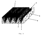
- the figure 3 schematically represents a plurality of solar collectors according to the invention forming a solar panel.
- the solar radiation is concentrated on a heat-transfer element 3 via a longitudinal reflector of cylindro-parabolic section 2.
- the solar radiation received by the heat transfer element 3 is absorbed, however part of this absorbed energy is re-emitted into the volume 7. This re-emitted energy can pass through the cover 1, it will then be permanently lost, or be absorbed by the cover 1 of the solar captor.
- the originality of the present invention is based on the use of a transformer 5 making it possible to use a portion of the solar radiation, preferably indirect solar radiation, to reduce energy losses by emissivity and to limit the amount of solar radiation. radiant energy.
- radiant energy is meant the energy emitted during the natural phenomenon called thermal emissivity, a phenomenon during which any matter struck by solar radiation emits infra-red radiation while cooling.
- the radiant energy comprises the energy reemitted by the elements that make up the solar collector, in particular by the heat transfer element.
- the solar collector according to the invention comprises a cover 1, a reflector with a cylindro-parabolic section 2, a heat-transfer element 3 and a transformer 5.
- the reflector assembly 2 and heat-transfer element 3 rests, or is included, in a layer of a thermal insulator 6 which rests in a cradle 8, or frame, on which the cover 1 rests ( Figure 1 ).
- Said cradle 8 is preferably of square or rectangle shape.
- the cover 1 is made of a material transparent to sunlight which has a low reflection rate and a high transmission.
- the material is a transparent synthetic material or a solar glass.
- Silicon glass means a glass which has a low iron content and whose surface is treated so as to reduce the effects of reflection. Surface treatment can be achieved by applying a Teflon film or film.
- the inner surface of the cover 1 may be covered with a substance that reflects infrared rays.
- the reflector 2 is of cylindro-parabolic section and of longitudinal shape. It makes it possible to obtain the concentration of solar radiation on the heat transfer element 3 which is located at the level of the focus of the dish.
- the reflector 2 has a highly reflective surface. Preferably, it has the appearance of a mirror.
- the reflector 2 may be made of a rigid material, for example glass, on which is applied a layer of a reflective substance.
- the reflector 2 is made of aluminum.
- the heat transfer element 3 in which circulates a heat transfer fluid is preferably rectangular section, circular section, oval section or square. It may be a metal or plastic tube resistant to the operating temperatures of the solar collector. Preferably, said heat-transfer element is made of copper or aluminum.
- the surface of the heat-transfer element 3 is covered, entirely or partially, with a layer of a material with high absorption of the solar spectrum and low thermal emission.
- the substance with high absorption of the solar spectrum and low thermal emission must cover the surface of said element 3 which is turned towards the opening of the dish.
- the heat transfer element 3 contains a gas or a coolant.
- the heat transfer gas can be air.
- the heat transfer fluid can be water, with or without additive, or for operating temperatures of more than 200 ° C, said fluid can be a stable oil, which does not fall apart, at high temperatures.
- the heat transfer element 3 has the characteristics of a heat pipe, also called "heatpipe”.
- a heat pipe is a hollow tube containing a heat transfer fluid under vacuum which is chosen according to its condensation / vaporization temperature.
- the heat pipe makes it possible to standardize the heat and to move as quickly as possible thanks to a phenomenon of phase change.
- the solar energy concentrated by the reflector within the converter will allow the vaporization of the coolant. This energy will then be restored at a cooler zone, in a heat exchanger for example, by the condensation of the heat transfer fluid.
- the heat-transfer element 3 is disposed inside a vacuum tube 4. Said tube 4 makes it possible to limit the energy losses of the heat-transfer element 3.
- said vacuum tube 4 is made of a transparent material, preferably it is solar glass or borosilicate glass. Said tube 4 may be covered with a layer of a substance having anti-reflection properties.
- the thermal insulation of the solar collector according to the invention is ensured on the one hand by the presence of the cover 1, and on the other hand, by a thermal insulator 6.
- the insulator 6 is polyurethane foam or polystyrene, rock fiber, or fiberglass.
- the transformer 5 makes it possible to reduce the heat losses due to the emissivity of the heat transfer element 3 and thus participates in the isolation of the solar collector by creating a thermal barrier against the infra-red reemissions of the heat transfer element 3. capturing part of the solar radiation, the transformer 5 heats up and re-emits radiant energy which is transferred to the volume 7.
- the transformer 5 is not in contact with the heat transfer element 3, neither directly nor indirectly. There is no solid-solid contact between said transformer 5 and said heat-transfer element 3.
- the transformer 5 may be in contact with said tube 4 provided that it is not in contact with the heat transfer element 3.
- the transformer 5 is fixed to the cover 1, and / or to the reflector 2, and / or to the vacuum tube 4. Said transformer 5 is located in the plane of symmetry of the section of the reflector, over the entire length of the solar collector. More specifically, if the heat transfer element 3, which is located at the focus of the parabolic trough reflector 2, is at the bottom of the dish, as shown in FIG. figure 1 , said transformer 5 will be disposed under the cover plate 1, while if the heat transfer element 3 is located under the cover 1, said transformer 5 will be disposed between the heat transfer element 3 and the bottom of the dish.
- the transformer 5 can take the form of two separate elements which are arranged on either side of the heat transfer element 3, one to the cover, the other to the bottom of the parable.
- the transformer 5 is a good heat conductor, preferably it is a carbon or silica blade, or it may be a blade, or a plate, metal or metal alloy.
- Said metal may be for example copper, aluminum, silver, gold, tungsten, brass, tin, or alloys of one or more of the metals mentioned above.
- the transformer 5 is made of any material which is coated with a substance with high thermal emission.
- Said substance can also be highly absorbed by the solar spectrum and has a high thermal emission.
- It can be any substance of blackish aspect, preferably of metallic nature. This can be carbon in all these forms, such as soot or graphite, or silica.
- This may be a metal such as copper, aluminum, anodized aluminum, silver, gold, tungsten, brass, tin, or alloys of one or more of the metals mentioned above .
- the transformer 5 has a rectangular shape.
- the transformer 5 may further comprise lamellae which can be interconnected ( figure 2 ).
- This particular embodiment of the element 5 allows a better diffusion and distribution of the radiation emitted by the transformer 5 in the volume 7. This helps to reduce any turbulence present in the volume 7.
- Volume 7 is the space between the reflector and the sensor cover. Said volume 7 contains a gas, or a fluid, capable of absorbing infrared radiation.
- the gas filling said volume 7 is carbon dioxide or air enriched with carbon dioxide or enriched with water vapor. It may still be one or more CFCs, methane or sulfur hexafluoride.
- the gas pressure of the volume 7 may be lower, equal to, or greater than atmospheric pressure.
- the solar collector may further comprise an opening for filling or discharging the fluid from the volume 7.
- the cradle 8, on which the cover assembly 1, reflector 2, heat transfer element 3 rests is made of metal, of aluminum for example, or of wood, or of composite material, or even a combination of these materials.
- the solar collector according to the invention advantageously comprises at least one means of tracking the sun.
- Said means makes it possible to follow the course of the sun and to adjust the position of the sensor in all directions in order to obtain optimum solar exposure, that is to say in order to allow the collector to adopt an ideal position relative to in the sun to capture the maximum energy. This is achieved through mechanical or hydraulic means.
- the solar collector according to the invention is used in the form of solar panels ( figure 3 ).
- the solar collector according to the invention is used for the production of electricity, heating, air conditioning or for desalination of water.
Abstract
Description
La présente invention se rapporte à un capteur solaire à concentration.The present invention relates to a concentrated solar collector.
Le principe général de fonctionnement d'un capteur solaire est de capter le rayonnement solaire pour le transformer en chaleur ou en électricité.The general principle of operation of a solar collector is to capture solar radiation to transform it into heat or electricity.
Il existe principalement deux types de capteurs, ceux qui sont « plans » et ceux « à concentration ». Les capteurs plans transforment le rayonnement solaire en chaleur sur toute la surface du capteur sans la concentrer, alors que les capteurs à concentration concentrent le rayonnement solaire au niveau du foyer grâce à un réflecteur ou grâce à des moyens optiques agissant par un effet de loupe.There are mainly two types of sensors, those which are "planes" and those "with concentration". Flat collectors convert solar radiation into heat over the entire surface of the collector without concentrating it, while concentrating collectors concentrate solar radiation at the focal point by means of a reflector or optical means acting by a magnifying glass effect.
Parmi les capteurs solaires à concentration, on distingue, d'une part, les capteurs utilisant un réflecteur en forme de parabole de révolution. Ces capteurs concentrent les rayons solaires au niveau du foyer de la parabole sur un moteur Stirling, moteur dans lequel la chaleur est transformée en mouvement, un mouvement lui-même transformé en électricité grâce à un alternateur.Among the solar collectors concentration, one distinguishes, on the one hand, the sensors using a reflector in the form of a parabola of revolution. These sensors concentrate the sun's rays at the focus of the dish on a Stirling engine, a motor in which heat is transformed into motion, a movement that is itself transformed into electricity by an alternator.
On distingue, d'autre part, les capteurs utilisant un réflecteur cylindro-parabolique qui concentrent les rayons solaires sur un convertisseur permettant de transformer les rayons solaires en chaleur. Le convertisseur comprend généralement un tube dans lequel circule un fluide caloporteur. Ce fluide va permettre de stocker la chaleur emmagasinée dans un réservoir de stockage ou de la restituer via un échangeur de chaleur.On the other hand, there are sensors using a cylindro-parabolic reflector that concentrate the sun's rays on a converter that transforms the sun's rays into heat. The converter generally comprises a tube in which circulates a coolant. This fluid will be used to store the heat stored in a storage tank or to return it via a heat exchanger.
Le convertisseur se doit de présenter non seulement une absorption élevée de tout le spectre du rayonnement solaire, mais aussi de posséder une émissivité, c'est-à-dire une réémission de chaleur, réduite. De plus, dans les capteurs solaires à concentration, la surface du convertisseur est généralement plus faible que celle de l'ouverture du capteur.The converter must not only have a high absorption of the entire spectrum of solar radiation, but also have an emissivity, that is to say a reduced heat retransmission. Moreover, in concentrating solar collectors, the surface of the converter is generally smaller than that of the opening of the sensor.
De tels capteurs solaires à concentration sont bien connus. Les convertisseurs employés présentent soit une section rectangulaire ou une section circulaire, les réflecteurs peuvent, quant à eux, être hémicylindriques ou cyclo-paraboliques.Such concentrating solar collectors are well known. The converters employed have either a rectangular section or a circular section, the reflectors may, for their part, be semi-cylindrical or cyclo-parabolic.
Les documents
Les documents
Différentes solutions ont été proposées afin d'améliorer l'efficacité des capteurs solaires à concentration. Certaines de ces solutions reposent sur l'emploi de différents matériaux pour la confection des éléments constitutifs d'un capteur et ce afin d'augmenter le rendement du transfert de l'énergie solaire en chaleur.Different solutions have been proposed to improve the efficiency of concentrating solar collectors. Some of these solutions are based on the use of different materials for making the constituent elements of a sensor and this in order to increase the efficiency of the transfer of solar energy into heat.
D'autres solutions, comme cela a été décrit dans les documents
Toutefois, ces solutions procurent un rendement énergétique encore bien trop faible et présentent l'inconvénient de ne pas limiter les pertes thermiques engendrées par un phénomène de réémission de chaleur notamment au niveau du convertisseur.However, these solutions provide an energy efficiency still far too low and have the disadvantage of not limiting the thermal losses generated by a heat re-emission phenomenon especially at the converter.
La présente invention vise à fournir un capteur solaire à concentration qui ne présente pas les inconvénients de l'état de la technique.The present invention aims to provide a concentrated solar collector which does not have the drawbacks of the state of the art.
Elle vise en particulier à fournir un capteur solaire à concentration présentant une efficacité améliorée. Elle vise en outre à fournir un capteur solaire qui peut être utilisé sous la forme de panneaux solaires, et qui peut, en outre, être utilisé pour la production d'électricité, de chauffage, de climatisation ou pour le dessalement de l'eau.In particular, it aims to provide a concentrated solar collector with improved efficiency. It also aims to provide a solar collector that can be used in the form of solar panels, and which can, in addition, be used for the production of electricity, heating, air conditioning or for desalination of water.
Les expressions « capteur », « cellule », « collecteur » sont utilisées indifféremment dans la suite de l'exposé de l'invention.The terms "sensor", "cell", "collector" are used interchangeably in the following description of the invention.
La présente invention décrit un capteur solaire à concentration comprenant une couverture transparente aux rayons solaires, un réflecteur de section cylindro-parabolique, un élément caloporteur et un transformateur permettant de diminuer les pertes d'énergie par émissivité, ledit transformateur n'étant pas en contact avec ledit élément caloporteur.The present invention discloses a concentrating solar collector comprising a transparent sunlight cover, a section reflector cylindro-parabolic, a heat transfer element and a transformer for reducing energy losses emissivity, said transformer not being in contact with said heat transfer element.
Selon des formes particulières de réalisation, l'invention comporte l'une ou plusieurs des caractéristiques suivantes :
- l'élément caloporteur est disposé à l'intérieur d'un tube à vide.
- le transformateur est fixé à la couverture et/ou au réflecteur et/ou au tube à vide.
- le transformateur est une lame située dans le plan de symétrie de la section du réflecteur.
- le transformateur est une lame de carbone ou de silice ou une lame métallique.
- le transformateur comprend des lamelles.
- le transformateur est recouvert d'une substance à forte émission thermique.
- la couverture du capteur est faite en matière synthétique transparente ou en verre solaire.
- le volume est un volume rempli d'un gaz ou d'un liquide.
- le capteur comprend en outre une ouverture permettant de remplir ou évacuer le gaz ou liquide du volume.
- l'élément caloporteur a une section rectangulaire, une section circulaire, une section ovale, ou a une forme carrée.
- l'élément caloporteur est un tube métallique ou un tube en matière plastique.
- la surface de l'élément caloporteur est recouverte partiellement ou entièrement d'une substance à forte absorption du spectre solaire et à faible émission thermique.
- l'élément caloporteur possède les caractéristiques d'un caloduc.
- l'élément caloporteur se situe au foyer du capteur solaire.
- l'élément caloporteur contient un liquide ou un gaz caloporteur.
- le capteur comprenant en outre un isolant thermique.
- l'isolant thermique est choisi parmi une mousse de polyuréthane, une mousse de polystyrène, de la fibre de roche, et de la fibre de verre.
- le capteur comprend en outre au moins un moyen de poursuite du soleil.
- the heat transfer element is disposed inside a vacuum tube.
- the transformer is fixed to the cover and / or the reflector and / or the vacuum tube.
- the transformer is a blade located in the plane of symmetry of the section of the reflector.
- the transformer is a carbon or silica blade or a metal blade.
- the transformer comprises lamellae.
- the transformer is covered with a substance with a high thermal emission.
- the sensor cover is made of transparent synthetic material or solar glass.
- the volume is a volume filled with a gas or a liquid.
- the sensor further comprises an opening for filling or discharging the gas or liquid volume.
- the heat transfer element has a rectangular section, a circular section, an oval section, or has a square shape.
- the heat transfer element is a metal tube or a plastic tube.
- the surface of the heat transfer element is partially or entirely covered with a substance with high absorption of the solar spectrum and low thermal emission.
- the heat transfer element has the characteristics of a heat pipe.
- the heat transfer element is located at the solar collector focus.
- the heat transfer element contains a liquid or a heat transfer gas.
- the sensor further comprising a thermal insulator.
- the thermal insulation is selected from polyurethane foam, polystyrene foam, rock fiber, and fiberglass.
- the sensor further comprises at least one sun tracking means.
La présente invention divulgue par ailleurs l'utilisation du capteur solaire sous la forme de panneaux solaires.The present invention further discloses the use of the solar collector in the form of solar panels.
La présente invention divulgue également l'utilisation du capteur solaire pour la production d'électricité ou de chauffage ou de climatisation ou pour le dessalement de l'eau.The present invention also discloses the use of the solar collector for the production of electricity or heating or air conditioning or for the desalination of water.
La
La
La
Dans le capteur solaire à concentration selon l'invention, le rayonnement solaire est concentré sur un élément caloporteur 3 par l'intermédiaire d'un réflecteur longitudinal de section cylindro-parabolique 2.In the solar concentration sensor according to the invention, the solar radiation is concentrated on a heat-
Le rayonnement solaire reçu par l'élément caloporteur 3 est absorbé, toutefois une partie de cette énergie absorbée est réémise dans le volume 7. Cette énergie réémise peut traverser la couverture 1, elle sera alors définitivement perdue, ou être absorbée par la couverture 1 du capteur solaire.The solar radiation received by the
L'originalité de la présente invention repose sur l'emploi d'un transformateur 5 permettant d'utiliser une partie du rayonnement solaire, de préférence le rayonnement solaire indirect, pour diminuer les pertes d'énergie par émissivité et pour limiter la quantité d'énergie radiante.The originality of the present invention is based on the use of a
On entend par « énergie radiante », l'énergie émise lors du phénomène naturel appelé émissivité thermique, un phénomène durant lequel toute matière frappée par le rayonnement solaire émet un rayonnement infra-rouge en se refroidissant. Ainsi, l'énergie radiante comprend l'énergie réémise par les éléments qui composent le collecteur solaire, en particulier par l'élément caloporteur.By "radiant energy" is meant the energy emitted during the natural phenomenon called thermal emissivity, a phenomenon during which any matter struck by solar radiation emits infra-red radiation while cooling. Thus, the radiant energy comprises the energy reemitted by the elements that make up the solar collector, in particular by the heat transfer element.
Le capteur solaire selon l'invention comprend une couverture 1, un réflecteur à section cylindro-parabolique 2, un élément caloporteur 3 ainsi qu'un transformateur 5.The solar collector according to the invention comprises a
Selon une forme particulière d'exécution de l'invention, l'ensemble réflecteur 2 et élément caloporteur 3 repose, ou est inclus, dans une couche d'un isolant thermique 6 qui repose dans un berceau 8, ou bâti, sur lequel la couverture 1 repose (
De préférence, la couverture 1 est faite d'un matériel transparent aux rayons solaires qui présente un faible taux de réflexion et une transmission élevée. Avantageusement, le matériel est une matière synthétique transparente ou un verre solaire.Preferably, the
On entend par « verre solaire » un verre qui possède une faible teneur en fer et dont la surface est traitée de façon à réduire les effets de réflexion. Le traitement de surface peut être obtenu par l'application d'une couche ou d'un film de Teflon."Solar glass" means a glass which has a low iron content and whose surface is treated so as to reduce the effects of reflection. Surface treatment can be achieved by applying a Teflon film or film.
Avantageusement, la surface intérieure de la couverture 1 peut être recouverte d'une substance réfléchissant les rayons infrarouges.Advantageously, the inner surface of the
Le réflecteur 2 est de section cylindro-parabolique et de forme longitudinale. Il permet d'obtenir la concentration du rayonnement solaire sur l'élément caloporteur 3 qui se situe au niveau du foyer de la parabole.The
Le réflecteur 2 possède une surface hautement réfléchissante. De préférence, il présente l'aspect d'un miroir. Dans ce but, le réflecteur 2 peut être fait d'un matériau rigide, du verre par exemple, sur lequel est appliquée une couche d'une substance réfléchissante.The
De préférence, le réflecteur 2 est en aluminium.Preferably, the
L'élément caloporteur 3 dans lequel circule un fluide caloporteur est de préférence à section rectangulaire, à section circulaire, à section ovale ou de forme carrée. Il peut s'agir d'un tube en métal ou en matière plastique résistant aux températures de fonctionnement du capteur solaire. De préférence, ledit élément caloporteur est en cuivre ou en aluminium.The
De préférence, la surface de l'élément caloporteur 3 est recouverte, entièrement ou partiellement, d'une couche d'une matière à forte absorption du spectre solaire et à faible émission thermique. Toutefois, dans le cas d'un recouvrement partiel dudit élément caloporteur 3, la substance à forte absorption du spectre solaire et à faible émission thermique devra recouvrir la surface dudit élément 3 qui est tournée vers l'ouverture de la parabole.Preferably, the surface of the heat-
L'élément caloporteur 3 contient un gaz ou un liquide caloporteur. Le gaz caloporteur peut être de l'air. Le fluide caloporteur peut être de l'eau, avec ou sans additif, ou pour des températures de fonctionnement de plus de 200 °C, ledit fluide peut être une huile stable, qui ne se désagrège pas, à hautes températures.The
Avantageusement l'élément caloporteur 3 possède les caractéristiques d'un caloduc, encore appelé « heatpipe ».Advantageously, the
Un caloduc est un tube creux contenant un fluide caloporteur sous vide qui est choisi en fonction de sa température de condensation/vaporisation. Le caloduc permet d'uniformiser la chaleur et de déplacer le plus rapidement possible grâce à un phénomène de changement de phase. L'énergie solaire concentrée par le réflecteur au sein du convertisseur va permettre la vaporisation du fluide caloporteur. Cette énergie sera ensuite restituée au niveau d'une zone plus froide, dans un échangeur de chaleur par exemple, par la condensation du fluide caloporteur.A heat pipe is a hollow tube containing a heat transfer fluid under vacuum which is chosen according to its condensation / vaporization temperature. The heat pipe makes it possible to standardize the heat and to move as quickly as possible thanks to a phenomenon of phase change. The solar energy concentrated by the reflector within the converter will allow the vaporization of the coolant. This energy will then be restored at a cooler zone, in a heat exchanger for example, by the condensation of the heat transfer fluid.
De préférence, l'élément caloporteur 3 est disposé à l'intérieur d'un tube sous vide 4. Ledit tube 4 permet de limiter les pertes d'énergie de l'élément caloporteur 3.Preferably, the heat-
Avantageusement, ledit tube à vide 4 est fait d'un matériel transparent, de préférence il s'agit de verre solaire ou de verre borosilicaté. Ledit tube 4 peut être recouvert d'une couche d'une substance ayant des propriétés anti-réflexion.Advantageously, said
L'isolation thermique du capteur solaire selon l'invention est assurée d'une part par la présence de la couverture 1, et d'autre part, par un isolant thermique 6.The thermal insulation of the solar collector according to the invention is ensured on the one hand by the presence of the
De préférence, l'isolant 6 est de la mousse de polyuréthane ou de polystyrène, de la fibre de roche, ou de la fibre de verre.Preferably, the
Le transformateur 5 permet de diminuer les pertes de chaleur due à l'émissivité de l'élément caloporteur 3 et participe ainsi à l'isolation du capteur solaire en créant une barrière thermique contre les réémissions infra-rouges de l'élément caloporteur 3. En captant une partie du rayonnement solaire, le transformateur 5 s'échauffe et réémet de l'énergie radiante qui est transférée au volume 7.The
Le transformateur 5 n'est pas en contact avec l'élément caloporteur 3, ni de façon directe, ni de façon indirecte. Il n'a y pas de contact solide-solide entre ledit transformateur 5 et ledit élément caloporteur 3. Dans la forme d'exécution dans laquelle l'élément caloporteur 3 est disposé à l'intérieur d'un tube sous vide 4, le transformateur 5 peut être en contact avec ledit tube 4 à condition de ne pas être en contact avec l'élément caloporteur 3.The
Le transformateur 5 est fixé à la couverture 1, et/ou au réflecteur 2, et/ou au tube à vide 4. Ledit transformateur 5 est situé dans le plan de symétrie de la section du réflecteur, sur toute la longueur du capteur solaire. Plus précisément, si l'élément caloporteur 3, qui se trouve au foyer du réflecteur cylindro-parabolique 2, se situe au bas de la parabole, comme représenté dans la
Le transformateur 5 est bon conducteur de chaleur, de préférence, il s'agit d'une lame de carbone ou de silice, ou bien il peut s'agir d'une lame, ou une plaque, de métal ou d'alliage métallique. Ledit métal peut être par exemple du cuivre, de l'aluminium, de l'argent, de l'or, du tungstène, du laiton, de l'étain, ou des alliages de l'un ou plusieurs des métaux cités précédemment.The
Dans une forme d'exécution préférée de l'invention, le transformateur 5 est fait d'un matériel quelconque qui est recouvert d'une substance à forte émission thermique. Ladite substance peut également être à forte absorption du spectre solaire et à forte émission thermique. Ce peut être toute substance d'aspect noirâtre, de préférence de nature métallique. Cela peut être du carbone sous toute ces formes, suie ou graphite par exemple, ou de la silice. Cela peut être un métal tel que le cuivre, l'aluminium, l'aluminium anodisé, l'argent, l'or, le tungstène, le laiton, l'étain, ou des alliages de l'un ou plusieurs des métaux cités précédemment.In a preferred embodiment of the invention, the
De préférence, le transformateur 5 a une forme rectangulaire.Preferably, the
Avantageusement, le transformateur 5 peut comprendre en outre des lamelles pouvant être reliées entre elles (
Le volume 7 correspond à l'espace existant entre le réflecteur et la couverture du capteur. Ledit volume 7 contient un gaz, ou un fluide, capable d'absorber le rayonnement infrarouge.
De préférence, le gaz remplissant ledit volume 7 est du dioxyde de carbone ou de l'air enrichi en dioxyde de carbone ou enrichie à la vapeur d'eau. Ce peut être encore un ou plusieurs CFC, du méthane ou de l'hexafluorure de soufre.Preferably, the gas filling said
La pression du gaz du volume 7 peut être inférieure, égale, ou supérieure, à la pression atmosphérique. A ces fins, le capteur solaire peut comprendre en outre une ouverture permettant de remplir ou évacuer le fluide du volume 7.The gas pressure of the
De préférence, le berceau 8, sur lequel repose l'ensemble couverture 1, réflecteur 2, élément caloporteur 3, est fait en métal, en aluminium par exemple, ou en bois, ou en matériau composite, ou bien encore en une combinaison de ces matériaux.Preferably, the
Le capteur solaire selon l'invention comprend avantageusement au moins un moyen de poursuite du soleil. Ledit moyen permet de suivre la course du soleil et d'ajuster la position du capteur dans toutes les directions afin d'obtenir une exposition solaire optimale, c'est-à-dire afin de permettre au collecteur d'adopter une position idéale par rapport au soleil pour en capter le maximum d'énergie. Ceci est obtenu grâce à des moyens mécaniques ou hydrauliques.The solar collector according to the invention advantageously comprises at least one means of tracking the sun. Said means makes it possible to follow the course of the sun and to adjust the position of the sensor in all directions in order to obtain optimum solar exposure, that is to say in order to allow the collector to adopt an ideal position relative to in the sun to capture the maximum energy. This is achieved through mechanical or hydraulic means.
De préférence le capteur solaire selon l'invention est utilisé sous la forme de panneaux solaires (
De préférence le capteur solaire selon l'invention est utilisé pour la production d'électricité, de chauffage, de climatisation ou pour le dessalement de l'eau.Preferably the solar collector according to the invention is used for the production of electricity, heating, air conditioning or for desalination of water.
Claims (20)
- Concentrating solar collector comprising a cover (1) transparent to solar rays, a reflector (2) of cylindro-parabolic cross section, said cover (1) and said reflector (2) defining a volume (7), and a heat-transfer element (3), characterized in that it further includes a transformer (5) for reducing the emissivity energy losses, said transformer (5) being covered by a substance having a high thermal emission, in that said transformer (5) absorbs some of the solar radiation and reemits heat into said volume (7) and in that said transformer (5) is not in contact with said heat-transfer element (3).
- Concentrating solar collector according to Claim 1, in which the heat-transfer element (3) is placed inside a transparent vacuum tube (4).
- Concentrating solar collector according to any of the preceding claims, in which the transformer (5) is fixed to the cover (1) and/or to the reflector (2) and/or to the vacuum tube (4).
- Concentrating solar collector according to any of the preceding claims, in which the transformer (5) is a plate lying in the plane of symmetry of the cross section of the reflector (2).
- Concentrating solar collector according to any of the preceding claims, in which the transformer (5) is a carbon or silica plate or a metal plate.
- Concentrating solar collector according to any of the preceding claims, in which the transformer (5) includes lamellae (9).
- Concentrating solar collector according to Claim 1, in which the cover (1) of the collector is made of a transparent plastic or of solar glass.
- Concentrating solar collector according to Claim 1, in which the volume (7) is a volume filled with a gas or with a liquid.
- Concentrating solar collector according to Claim 8, in which said collector further includes an opening in order for the gas or the liquid to be injected into the volume (7) or to be moved therefrom.
- Concentrating solar collector according to Claim 1, in which the heat-transfer element (3) has a rectangular cross section, a circular cross section or an oval cross section, or has a square shape.
- Concentrating solar collector according to Claim 1, in which the heat-transfer element (3) is a metal tube or a plastic tube.
- Concentrating solar collector according to Claim 1, in which the surface of the heat-transfer element (3) is partly or entirely covered with a substance having a high absorption of the solar spectrum and a low thermal emission.
- Concentrating solar collector according to Claim 1, in which the heat-transfer element (3) possesses the characteristics of a heat pipe.
- Concentrating solar collector according to Claim 1, in which the heat-transfer element (3) is located at the focus of the solar collector.
- Concentrating solar collector according to Claim 1, in which the heat-transfer element (3) contains a heat-transfer liquid or gas.
- Concentrating solar collector according to Claim 1, in which said collector further includes a thermal insulator (6).
- Concentrating solar collector according to Claim 16, in which the insulator (6) is chosen from a polyurethane foam, a polystyrene foam, rock fibre and glass fibre.
- Concentrating solar collector according to any of the preceding claims, in which said collector further includes at least one means for tracking the sun.
- Use of the solar collector according to any of the preceding claims, in the form of solar panels.
- Use of the solar collector according to any of the preceding claims for the generation of electricity or for heating or for air conditioning or for water desalination.
Priority Applications (9)
| Application Number | Priority Date | Filing Date | Title |
|---|---|---|---|
| EP06075432A EP1826505B1 (en) | 2006-02-24 | 2006-02-24 | Solar collector with concentration |
| ES06075432T ES2306356T3 (en) | 2006-02-24 | 2006-02-24 | SOLAR CONCENTRATION RECEIVER. |
| DE602006000906T DE602006000906T2 (en) | 2006-02-24 | 2006-02-24 | Solar panel with concentration |
| AT06075432T ATE391889T1 (en) | 2006-02-24 | 2006-02-24 | SOLAR COLLECTOR WITH CONCENTRATION |
| US12/280,360 US20090013990A1 (en) | 2006-02-24 | 2007-02-22 | Concentrating solar collector |
| CNA200780009701XA CN101405545A (en) | 2006-02-24 | 2007-02-22 | Solar collector with concentration |
| BRPI0708239-8A BRPI0708239A2 (en) | 2006-02-24 | 2007-02-22 | solar collector concentrator |
| PCT/EP2007/001531 WO2007096162A1 (en) | 2006-02-24 | 2007-02-22 | Concentrating collector |
| MA31237A MA30281B1 (en) | 2006-02-24 | 2008-09-11 | CONCENTRATED SOLAR SENSOR |
Applications Claiming Priority (1)
| Application Number | Priority Date | Filing Date | Title |
|---|---|---|---|
| EP06075432A EP1826505B1 (en) | 2006-02-24 | 2006-02-24 | Solar collector with concentration |
Publications (2)
| Publication Number | Publication Date |
|---|---|
| EP1826505A1 EP1826505A1 (en) | 2007-08-29 |
| EP1826505B1 true EP1826505B1 (en) | 2008-04-09 |
Family
ID=36645624
Family Applications (1)
| Application Number | Title | Priority Date | Filing Date |
|---|---|---|---|
| EP06075432A Not-in-force EP1826505B1 (en) | 2006-02-24 | 2006-02-24 | Solar collector with concentration |
Country Status (9)
| Country | Link |
|---|---|
| US (1) | US20090013990A1 (en) |
| EP (1) | EP1826505B1 (en) |
| CN (1) | CN101405545A (en) |
| AT (1) | ATE391889T1 (en) |
| BR (1) | BRPI0708239A2 (en) |
| DE (1) | DE602006000906T2 (en) |
| ES (1) | ES2306356T3 (en) |
| MA (1) | MA30281B1 (en) |
| WO (1) | WO2007096162A1 (en) |
Cited By (1)
| Publication number | Priority date | Publication date | Assignee | Title |
|---|---|---|---|---|
| WO2010114501A2 (en) | 2009-04-01 | 2010-10-07 | Mustafa Gunay | A system absorbing solar energy by concentration |
Families Citing this family (12)
| Publication number | Priority date | Publication date | Assignee | Title |
|---|---|---|---|---|
| EP2000748A3 (en) * | 2007-06-06 | 2014-04-02 | Herr Orhan Ustun | Collector element to generate heat from sun radiation and protective cover therefor |
| ITUD20080088A1 (en) * | 2008-04-21 | 2009-10-22 | Costruzioni Solari S R L | DEVELOPMENT AND CONCENTRATION OF SOLAR ENERGY |
| US8069849B2 (en) * | 2009-02-13 | 2011-12-06 | Matalon Energy, Llc | Parabolic solar collector |
| FR2942303B1 (en) * | 2009-02-18 | 2013-06-28 | Ludovic Deblois | UNI-AXIAL SOLAR CONCENTRATOR AND CYLINDRO-PARABOLIC MULTI-MIRRORS |
| EP2366963A1 (en) | 2010-03-17 | 2011-09-21 | Solarafi S.à.r.l. | Concentrating solar collector |
| IT1402134B1 (en) * | 2010-07-30 | 2013-08-28 | Innova Technology Solutions S P A | SOLAR RADIATION HEAT ABSORBER FOR STIRLING ENGINE |
| KR101313723B1 (en) * | 2010-11-27 | 2013-10-01 | 요크공조(주) | structure for condensing sunlight and Apparatus for transmitting sunlight |
| US20120266865A1 (en) * | 2011-03-22 | 2012-10-25 | Lawrence John Queen | Solar Collecting System Using a Rock Mass |
| US9194378B2 (en) * | 2012-06-29 | 2015-11-24 | Black Sun Planetary Solutions, Inc. | Electromagnetic radiation collector |
| JP2014052153A (en) * | 2012-09-10 | 2014-03-20 | Tohoku Univ | Solar heat collection device |
| WO2016178056A1 (en) * | 2015-05-02 | 2016-11-10 | Wijewickrama Janaka | A system that uses greenhouse gases to increase the receiver efficiency of concentrated solar power systems |
| US9639535B1 (en) * | 2015-12-16 | 2017-05-02 | Waste Repurposing International, Inc. | Waste identification systems and methods |
Family Cites Families (14)
| Publication number | Priority date | Publication date | Assignee | Title |
|---|---|---|---|---|
| US3321012A (en) | 1963-05-20 | 1967-05-23 | Ind Institution International | Solar heat exchanger |
| US3875926A (en) * | 1974-02-21 | 1975-04-08 | Matthew William Frank | Solar thermal energy collection system |
| AT344375B (en) | 1974-10-08 | 1978-07-25 | Klaus Dipl Ing Dr Tech Ruzicka | SOLAR ENERGY CONVERTER |
| US4074706A (en) * | 1975-07-30 | 1978-02-21 | Enthone, Incorporated | Solar collector having selective film of improved stability to liquid water condensate |
| US4059094A (en) | 1975-12-04 | 1977-11-22 | Barrio De Mendoza Cayo Petroni | Solar energy collector apparatus |
| US4024852A (en) | 1976-02-05 | 1977-05-24 | Esperance Paul M L | Solar energy reflector-collector |
| US4131109A (en) * | 1977-05-25 | 1978-12-26 | Jordan College | Solar collector |
| NL187543C (en) * | 1978-08-21 | 1991-10-04 | Patlico Rights Nv | SOLAR HEAT COLLECTOR. |
| US4220136A (en) * | 1978-09-13 | 1980-09-02 | Penney Richard J | Solar energy collector |
| DE2842400A1 (en) * | 1978-09-29 | 1980-04-17 | Ibm Deutschland | SOLAR ENERGY COLLECTOR WITH LENS GRID |
| US4337756A (en) * | 1978-12-05 | 1982-07-06 | Sergio Serapioni | Panel for collecting solar energy with reduced losses |
| FR2473689A1 (en) | 1980-01-09 | 1981-07-17 | Cassimatis Jean | CONCENTRATED SOLAR SENSORS COMPRISING A FIXED CYLINDRICAL REFLECTOR |
| AT402114B (en) | 1993-03-25 | 1997-02-25 | Grossauer Johann | SOLAR PANEL |
| US6454026B1 (en) * | 2000-09-08 | 2002-09-24 | Sandvik Ab | Percussive down-the-hole hammer for rock drilling, a top sub used therein and a method for adjusting air pressure |
-
2006
- 2006-02-24 ES ES06075432T patent/ES2306356T3/en active Active
- 2006-02-24 AT AT06075432T patent/ATE391889T1/en not_active IP Right Cessation
- 2006-02-24 EP EP06075432A patent/EP1826505B1/en not_active Not-in-force
- 2006-02-24 DE DE602006000906T patent/DE602006000906T2/en active Active
-
2007
- 2007-02-22 US US12/280,360 patent/US20090013990A1/en not_active Abandoned
- 2007-02-22 CN CNA200780009701XA patent/CN101405545A/en active Pending
- 2007-02-22 WO PCT/EP2007/001531 patent/WO2007096162A1/en active Application Filing
- 2007-02-22 BR BRPI0708239-8A patent/BRPI0708239A2/en not_active IP Right Cessation
-
2008
- 2008-09-11 MA MA31237A patent/MA30281B1/en unknown
Cited By (1)
| Publication number | Priority date | Publication date | Assignee | Title |
|---|---|---|---|---|
| WO2010114501A2 (en) | 2009-04-01 | 2010-10-07 | Mustafa Gunay | A system absorbing solar energy by concentration |
Also Published As
| Publication number | Publication date |
|---|---|
| BRPI0708239A2 (en) | 2011-05-24 |
| ATE391889T1 (en) | 2008-04-15 |
| CN101405545A (en) | 2009-04-08 |
| DE602006000906D1 (en) | 2008-05-21 |
| ES2306356T3 (en) | 2008-11-01 |
| DE602006000906T2 (en) | 2009-01-22 |
| MA30281B1 (en) | 2009-03-02 |
| WO2007096162A1 (en) | 2007-08-30 |
| US20090013990A1 (en) | 2009-01-15 |
| EP1826505A1 (en) | 2007-08-29 |
Similar Documents
| Publication | Publication Date | Title |
|---|---|---|
| EP1826505B1 (en) | Solar collector with concentration | |
| FR2488982A1 (en) | SOLAR ENERGY SENSOR COMPRISING A SOLAR ENERGY ABSORBING ELEMENT CONSISTING OF A THIN COATED FILM AND METHOD FOR MANUFACTURING SUCH A SENSOR | |
| WO2010092283A2 (en) | Solar collector, and power-generating plant including such solar collectors | |
| Salvi et al. | Technological advances to maximize solar collector energy output: a review | |
| WO2011080330A2 (en) | Method for the automatic orientation of a solar panel device and device operating according to said method | |
| FR2956727A1 (en) | THERMAL SOLAR PANEL WITH HIGH PERFORMANCE | |
| FR2461212A1 (en) | SOLAR SENSOR AND APPARATUS USING SUCH SENSORS | |
| FR2501846A1 (en) | Tube for heat exchanger - has internal tubes and helical fin in annular space which forms part of solar heat collector fluid circuit | |
| JP5417090B2 (en) | Solar heat converter | |
| EP0018900B1 (en) | High efficiency panel for emitting or collecting radiating energy, and process for the utilisation of such a panel | |
| EP2366963A1 (en) | Concentrating solar collector | |
| FR2501347A1 (en) | Solar collector for powering refrigerator - has vacuum tube filled with active solid and specified fluid acting on absorption cycle | |
| JP2010085080A (en) | Sunlight thermal converting device | |
| FR2945857A1 (en) | Device for transmitting heat energy to gaseous or liquid fluid in e.g. solar thermal station, has frame supporting mobile structure for aligning structure so as to maintain solar light in common optical plane of mirrors | |
| FR2902181A1 (en) | Thermal conductor for vacuum solar sensor, has central part receiving heat transferring unit made of heat conductive material e.g. aluminum and its alloy, copper and its alloy or magnesium and its alloy, where unit is obtained by extrusion | |
| WO2014181047A1 (en) | Device for collecting, exchanging, and thermally storing solar energy | |
| EP2715244B1 (en) | Longer life solar power plant receiver | |
| CN2775555Y (en) | Solar enrgy U-shape tube light focus heat collector | |
| FR2489943A1 (en) | DIFFERENTIAL THERMAL EMISSION POWER DEVICE FOR THE TRANSPORT OF AN ENERGY, SUCH AS SOLAR ENERGY | |
| FR3096061A1 (en) | WATER COLLECTION SYSTEM BY CONDENSATION OF ATMOSPHERIC WATER VAPOR | |
| WO2015118256A1 (en) | Linear-concentration solar power plant having a secondary reflector | |
| FR3097304A1 (en) | HYBRID RADIATION ABSORBER FOR SOLAR POWER PLANTS, AND PROCESS FOR PREPARING SUCH AN ABSORBER | |
| BE1020701A3 (en) | COUPLING OF TURBOPOMPE FOR FILLED SALTS. | |
| FR3075332A1 (en) | SOLAR RADIATION ABSORBER, SYSTEM AND METHOD THEREOF | |
| FR2613045A1 (en) | Compact thermosyphon solar water heater with concentration |
Legal Events
| Date | Code | Title | Description |
|---|---|---|---|
| PUAI | Public reference made under article 153(3) epc to a published international application that has entered the european phase |
Free format text: ORIGINAL CODE: 0009012 |
|
| 17P | Request for examination filed |
Effective date: 20061214 |
|
| AK | Designated contracting states |
Kind code of ref document: A1 Designated state(s): AT BE BG CH CY CZ DE DK EE ES FI FR GB GR HU IE IS IT LI LT LU LV MC NL PL PT RO SE SI SK TR |
|
| AX | Request for extension of the european patent |
Extension state: AL BA HR MK YU |
|
| GRAP | Despatch of communication of intention to grant a patent |
Free format text: ORIGINAL CODE: EPIDOSNIGR1 |
|
| GRAS | Grant fee paid |
Free format text: ORIGINAL CODE: EPIDOSNIGR3 |
|
| GRAA | (expected) grant |
Free format text: ORIGINAL CODE: 0009210 |
|
| AK | Designated contracting states |
Kind code of ref document: B1 Designated state(s): AT BE BG CH CY CZ DE DK EE ES FI FR GB GR HU IE IS IT LI LT LU LV MC NL PL PT RO SE SI SK TR |
|
| REG | Reference to a national code |
Ref country code: GB Ref legal event code: FG4D Free format text: NOT ENGLISH |
|
| REG | Reference to a national code |
Ref country code: CH Ref legal event code: EP |
|
| AKX | Designation fees paid |
Designated state(s): AT BE BG CH CY CZ DE DK EE ES FI FR GB GR HU IE IS IT LI LT LU LV MC NL PL PT RO SE SI SK TR |
|
| REG | Reference to a national code |
Ref country code: IE Ref legal event code: FG4D Free format text: LANGUAGE OF EP DOCUMENT: FRENCH |
|
| REF | Corresponds to: |
Ref document number: 602006000906 Country of ref document: DE Date of ref document: 20080521 Kind code of ref document: P |
|
| RAP2 | Party data changed (patent owner data changed or rights of a patent transferred) |
Owner name: MATTIOLI, RAYMOND |
|
| RIN2 | Information on inventor provided after grant (corrected) |
Inventor name: MATTIOLI, RAYMOND |
|
| REG | Reference to a national code |
Ref country code: GR Ref legal event code: EP Ref document number: 20080401733 Country of ref document: GR |
|
| PG25 | Lapsed in a contracting state [announced via postgrant information from national office to epo] |
Ref country code: SI Free format text: LAPSE BECAUSE OF FAILURE TO SUBMIT A TRANSLATION OF THE DESCRIPTION OR TO PAY THE FEE WITHIN THE PRESCRIBED TIME-LIMIT Effective date: 20080409 |
|
| NLV1 | Nl: lapsed or annulled due to failure to fulfill the requirements of art. 29p and 29m of the patents act | ||
| PG25 | Lapsed in a contracting state [announced via postgrant information from national office to epo] |
Ref country code: PT Free format text: LAPSE BECAUSE OF FAILURE TO SUBMIT A TRANSLATION OF THE DESCRIPTION OR TO PAY THE FEE WITHIN THE PRESCRIBED TIME-LIMIT Effective date: 20080911 Ref country code: BG Free format text: LAPSE BECAUSE OF FAILURE TO SUBMIT A TRANSLATION OF THE DESCRIPTION OR TO PAY THE FEE WITHIN THE PRESCRIBED TIME-LIMIT Effective date: 20080709 Ref country code: FI Free format text: LAPSE BECAUSE OF FAILURE TO SUBMIT A TRANSLATION OF THE DESCRIPTION OR TO PAY THE FEE WITHIN THE PRESCRIBED TIME-LIMIT Effective date: 20080409 Ref country code: NL Free format text: LAPSE BECAUSE OF FAILURE TO SUBMIT A TRANSLATION OF THE DESCRIPTION OR TO PAY THE FEE WITHIN THE PRESCRIBED TIME-LIMIT Effective date: 20080409 |
|
| REG | Reference to a national code |
Ref country code: ES Ref legal event code: FG2A Ref document number: 2306356 Country of ref document: ES Kind code of ref document: T3 |
|
| PG25 | Lapsed in a contracting state [announced via postgrant information from national office to epo] |
Ref country code: LV Free format text: LAPSE BECAUSE OF FAILURE TO SUBMIT A TRANSLATION OF THE DESCRIPTION OR TO PAY THE FEE WITHIN THE PRESCRIBED TIME-LIMIT Effective date: 20080409 Ref country code: AT Free format text: LAPSE BECAUSE OF FAILURE TO SUBMIT A TRANSLATION OF THE DESCRIPTION OR TO PAY THE FEE WITHIN THE PRESCRIBED TIME-LIMIT Effective date: 20080409 Ref country code: PL Free format text: LAPSE BECAUSE OF FAILURE TO SUBMIT A TRANSLATION OF THE DESCRIPTION OR TO PAY THE FEE WITHIN THE PRESCRIBED TIME-LIMIT Effective date: 20080409 |
|
| REG | Reference to a national code |
Ref country code: IE Ref legal event code: FD4D |
|
| REG | Reference to a national code |
Ref country code: FR Ref legal event code: CA |
|
| PG25 | Lapsed in a contracting state [announced via postgrant information from national office to epo] |
Ref country code: IS Free format text: LAPSE BECAUSE OF FAILURE TO SUBMIT A TRANSLATION OF THE DESCRIPTION OR TO PAY THE FEE WITHIN THE PRESCRIBED TIME-LIMIT Effective date: 20080809 |
|
| PG25 | Lapsed in a contracting state [announced via postgrant information from national office to epo] |
Ref country code: IE Free format text: LAPSE BECAUSE OF FAILURE TO SUBMIT A TRANSLATION OF THE DESCRIPTION OR TO PAY THE FEE WITHIN THE PRESCRIBED TIME-LIMIT Effective date: 20080409 Ref country code: SE Free format text: LAPSE BECAUSE OF FAILURE TO SUBMIT A TRANSLATION OF THE DESCRIPTION OR TO PAY THE FEE WITHIN THE PRESCRIBED TIME-LIMIT Effective date: 20080709 Ref country code: LT Free format text: LAPSE BECAUSE OF FAILURE TO SUBMIT A TRANSLATION OF THE DESCRIPTION OR TO PAY THE FEE WITHIN THE PRESCRIBED TIME-LIMIT Effective date: 20080409 Ref country code: DK Free format text: LAPSE BECAUSE OF FAILURE TO SUBMIT A TRANSLATION OF THE DESCRIPTION OR TO PAY THE FEE WITHIN THE PRESCRIBED TIME-LIMIT Effective date: 20080409 Ref country code: CZ Free format text: LAPSE BECAUSE OF FAILURE TO SUBMIT A TRANSLATION OF THE DESCRIPTION OR TO PAY THE FEE WITHIN THE PRESCRIBED TIME-LIMIT Effective date: 20080409 |
|
| PLBE | No opposition filed within time limit |
Free format text: ORIGINAL CODE: 0009261 |
|
| STAA | Information on the status of an ep patent application or granted ep patent |
Free format text: STATUS: NO OPPOSITION FILED WITHIN TIME LIMIT |
|
| PG25 | Lapsed in a contracting state [announced via postgrant information from national office to epo] |
Ref country code: SK Free format text: LAPSE BECAUSE OF FAILURE TO SUBMIT A TRANSLATION OF THE DESCRIPTION OR TO PAY THE FEE WITHIN THE PRESCRIBED TIME-LIMIT Effective date: 20080409 Ref country code: RO Free format text: LAPSE BECAUSE OF FAILURE TO SUBMIT A TRANSLATION OF THE DESCRIPTION OR TO PAY THE FEE WITHIN THE PRESCRIBED TIME-LIMIT Effective date: 20080409 |
|
| 26N | No opposition filed |
Effective date: 20090112 |
|
| PG25 | Lapsed in a contracting state [announced via postgrant information from national office to epo] |
Ref country code: EE Free format text: LAPSE BECAUSE OF FAILURE TO SUBMIT A TRANSLATION OF THE DESCRIPTION OR TO PAY THE FEE WITHIN THE PRESCRIBED TIME-LIMIT Effective date: 20080409 |
|
| BERE | Be: lapsed |
Owner name: MATTIOLI, RAYMOND Effective date: 20090228 |
|
| PG25 | Lapsed in a contracting state [announced via postgrant information from national office to epo] |
Ref country code: MC Free format text: LAPSE BECAUSE OF NON-PAYMENT OF DUE FEES Effective date: 20090228 Ref country code: CY Free format text: LAPSE BECAUSE OF FAILURE TO SUBMIT A TRANSLATION OF THE DESCRIPTION OR TO PAY THE FEE WITHIN THE PRESCRIBED TIME-LIMIT Effective date: 20080409 |
|
| PG25 | Lapsed in a contracting state [announced via postgrant information from national office to epo] |
Ref country code: BE Free format text: LAPSE BECAUSE OF NON-PAYMENT OF DUE FEES Effective date: 20090228 |
|
| PGFP | Annual fee paid to national office [announced via postgrant information from national office to epo] |
Ref country code: ES Payment date: 20100205 Year of fee payment: 5 |
|
| PGFP | Annual fee paid to national office [announced via postgrant information from national office to epo] |
Ref country code: FR Payment date: 20100324 Year of fee payment: 5 Ref country code: IT Payment date: 20100217 Year of fee payment: 5 |
|
| PGFP | Annual fee paid to national office [announced via postgrant information from national office to epo] |
Ref country code: DE Payment date: 20100202 Year of fee payment: 5 Ref country code: TR Payment date: 20100208 Year of fee payment: 5 |
|
| REG | Reference to a national code |
Ref country code: CH Ref legal event code: PL |
|
| GBPC | Gb: european patent ceased through non-payment of renewal fee |
Effective date: 20100224 |
|
| PG25 | Lapsed in a contracting state [announced via postgrant information from national office to epo] |
Ref country code: LI Free format text: LAPSE BECAUSE OF NON-PAYMENT OF DUE FEES Effective date: 20100228 Ref country code: CH Free format text: LAPSE BECAUSE OF NON-PAYMENT OF DUE FEES Effective date: 20100228 |
|
| PGFP | Annual fee paid to national office [announced via postgrant information from national office to epo] |
Ref country code: GR Payment date: 20100126 Year of fee payment: 5 |
|
| PG25 | Lapsed in a contracting state [announced via postgrant information from national office to epo] |
Ref country code: GB Free format text: LAPSE BECAUSE OF NON-PAYMENT OF DUE FEES Effective date: 20100224 |
|
| PG25 | Lapsed in a contracting state [announced via postgrant information from national office to epo] |
Ref country code: LU Free format text: LAPSE BECAUSE OF NON-PAYMENT OF DUE FEES Effective date: 20090224 |
|
| PG25 | Lapsed in a contracting state [announced via postgrant information from national office to epo] |
Ref country code: HU Free format text: LAPSE BECAUSE OF FAILURE TO SUBMIT A TRANSLATION OF THE DESCRIPTION OR TO PAY THE FEE WITHIN THE PRESCRIBED TIME-LIMIT Effective date: 20081010 |
|
| REG | Reference to a national code |
Ref country code: FR Ref legal event code: ST Effective date: 20111102 |
|
| PG25 | Lapsed in a contracting state [announced via postgrant information from national office to epo] |
Ref country code: GR Free format text: LAPSE BECAUSE OF NON-PAYMENT OF DUE FEES Effective date: 20110902 |
|
| PG25 | Lapsed in a contracting state [announced via postgrant information from national office to epo] |
Ref country code: IT Free format text: LAPSE BECAUSE OF NON-PAYMENT OF DUE FEES Effective date: 20110224 |
|
| PG25 | Lapsed in a contracting state [announced via postgrant information from national office to epo] |
Ref country code: FR Free format text: LAPSE BECAUSE OF NON-PAYMENT OF DUE FEES Effective date: 20110228 |
|
| REG | Reference to a national code |
Ref country code: DE Ref legal event code: R119 Ref document number: 602006000906 Country of ref document: DE Effective date: 20110901 |
|
| REG | Reference to a national code |
Ref country code: ES Ref legal event code: FD2A Effective date: 20120411 |
|
| PG25 | Lapsed in a contracting state [announced via postgrant information from national office to epo] |
Ref country code: ES Free format text: LAPSE BECAUSE OF NON-PAYMENT OF DUE FEES Effective date: 20110225 |
|
| PG25 | Lapsed in a contracting state [announced via postgrant information from national office to epo] |
Ref country code: DE Free format text: LAPSE BECAUSE OF NON-PAYMENT OF DUE FEES Effective date: 20110901 |
|
| PG25 | Lapsed in a contracting state [announced via postgrant information from national office to epo] |
Ref country code: TR Free format text: LAPSE BECAUSE OF NON-PAYMENT OF DUE FEES Effective date: 20110224 |