EP1826460A1 - Manufacturing method for an input disc, output disc and power roller of a toroidal continuously variable transmission - Google Patents
Manufacturing method for an input disc, output disc and power roller of a toroidal continuously variable transmission Download PDFInfo
- Publication number
- EP1826460A1 EP1826460A1 EP07004192A EP07004192A EP1826460A1 EP 1826460 A1 EP1826460 A1 EP 1826460A1 EP 07004192 A EP07004192 A EP 07004192A EP 07004192 A EP07004192 A EP 07004192A EP 1826460 A1 EP1826460 A1 EP 1826460A1
- Authority
- EP
- European Patent Office
- Prior art keywords
- less
- rolling
- sliding member
- hrc
- amount
- Prior art date
- Legal status (The legal status is an assumption and is not a legal conclusion. Google has not performed a legal analysis and makes no representation as to the accuracy of the status listed.)
- Granted
Links
- 230000005540 biological transmission Effects 0.000 title claims abstract description 36
- 238000004519 manufacturing process Methods 0.000 title claims description 12
- 238000005096 rolling process Methods 0.000 claims abstract description 92
- 229910000831 Steel Inorganic materials 0.000 claims abstract description 36
- 239000010959 steel Substances 0.000 claims abstract description 36
- 230000009467 reduction Effects 0.000 claims abstract description 28
- 238000007906 compression Methods 0.000 claims abstract description 25
- 230000006835 compression Effects 0.000 claims abstract description 25
- 238000005496 tempering Methods 0.000 claims description 34
- 238000010791 quenching Methods 0.000 claims description 31
- 230000000171 quenching effect Effects 0.000 claims description 31
- 229910001566 austenite Inorganic materials 0.000 claims description 26
- 238000000034 method Methods 0.000 claims description 23
- 230000008569 process Effects 0.000 claims description 22
- 230000000717 retained effect Effects 0.000 claims description 21
- 239000000463 material Substances 0.000 claims description 19
- 238000003754 machining Methods 0.000 claims description 9
- 230000000694 effects Effects 0.000 abstract description 4
- 230000000052 comparative effect Effects 0.000 description 20
- 230000007423 decrease Effects 0.000 description 14
- 238000005480 shot peening Methods 0.000 description 13
- 238000012360 testing method Methods 0.000 description 10
- 238000010438 heat treatment Methods 0.000 description 9
- 238000012795 verification Methods 0.000 description 7
- 239000002994 raw material Substances 0.000 description 5
- 230000008859 change Effects 0.000 description 4
- 238000010276 construction Methods 0.000 description 4
- 238000010586 diagram Methods 0.000 description 4
- 230000020169 heat generation Effects 0.000 description 4
- 239000013078 crystal Substances 0.000 description 3
- 230000033001 locomotion Effects 0.000 description 3
- 239000000203 mixture Substances 0.000 description 3
- 230000006872 improvement Effects 0.000 description 2
- 239000000314 lubricant Substances 0.000 description 2
- 238000012545 processing Methods 0.000 description 2
- 238000011160 research Methods 0.000 description 2
- 229910045601 alloy Inorganic materials 0.000 description 1
- 239000000956 alloy Substances 0.000 description 1
- 230000015572 biosynthetic process Effects 0.000 description 1
- 238000006243 chemical reaction Methods 0.000 description 1
- 230000008878 coupling Effects 0.000 description 1
- 238000010168 coupling process Methods 0.000 description 1
- 238000005859 coupling reaction Methods 0.000 description 1
- 238000005520 cutting process Methods 0.000 description 1
- 230000003247 decreasing effect Effects 0.000 description 1
- 230000008021 deposition Effects 0.000 description 1
- 238000011161 development Methods 0.000 description 1
- 238000002474 experimental method Methods 0.000 description 1
- 238000005242 forging Methods 0.000 description 1
- 239000000446 fuel Substances 0.000 description 1
- 239000012535 impurity Substances 0.000 description 1
- 239000004615 ingredient Substances 0.000 description 1
- 229910000734 martensite Inorganic materials 0.000 description 1
- 238000005259 measurement Methods 0.000 description 1
- 239000002245 particle Substances 0.000 description 1
- 230000001105 regulatory effect Effects 0.000 description 1
- 239000007787 solid Substances 0.000 description 1
- 230000006641 stabilisation Effects 0.000 description 1
- 238000011105 stabilization Methods 0.000 description 1
Images


Classifications
-
- F—MECHANICAL ENGINEERING; LIGHTING; HEATING; WEAPONS; BLASTING
- F16—ENGINEERING ELEMENTS AND UNITS; GENERAL MEASURES FOR PRODUCING AND MAINTAINING EFFECTIVE FUNCTIONING OF MACHINES OR INSTALLATIONS; THERMAL INSULATION IN GENERAL
- F16H—GEARING
- F16H55/00—Elements with teeth or friction surfaces for conveying motion; Worms, pulleys or sheaves for gearing mechanisms
- F16H55/32—Friction members
- F16H55/34—Non-adjustable friction discs
-
- C—CHEMISTRY; METALLURGY
- C21—METALLURGY OF IRON
- C21D—MODIFYING THE PHYSICAL STRUCTURE OF FERROUS METALS; GENERAL DEVICES FOR HEAT TREATMENT OF FERROUS OR NON-FERROUS METALS OR ALLOYS; MAKING METAL MALLEABLE, e.g. BY DECARBURISATION OR TEMPERING
- C21D1/00—General methods or devices for heat treatment, e.g. annealing, hardening, quenching or tempering
- C21D1/18—Hardening; Quenching with or without subsequent tempering
-
- C—CHEMISTRY; METALLURGY
- C21—METALLURGY OF IRON
- C21D—MODIFYING THE PHYSICAL STRUCTURE OF FERROUS METALS; GENERAL DEVICES FOR HEAT TREATMENT OF FERROUS OR NON-FERROUS METALS OR ALLOYS; MAKING METAL MALLEABLE, e.g. BY DECARBURISATION OR TEMPERING
- C21D6/00—Heat treatment of ferrous alloys
- C21D6/002—Heat treatment of ferrous alloys containing Cr
-
- C—CHEMISTRY; METALLURGY
- C21—METALLURGY OF IRON
- C21D—MODIFYING THE PHYSICAL STRUCTURE OF FERROUS METALS; GENERAL DEVICES FOR HEAT TREATMENT OF FERROUS OR NON-FERROUS METALS OR ALLOYS; MAKING METAL MALLEABLE, e.g. BY DECARBURISATION OR TEMPERING
- C21D6/00—Heat treatment of ferrous alloys
- C21D6/008—Heat treatment of ferrous alloys containing Si
-
- C—CHEMISTRY; METALLURGY
- C21—METALLURGY OF IRON
- C21D—MODIFYING THE PHYSICAL STRUCTURE OF FERROUS METALS; GENERAL DEVICES FOR HEAT TREATMENT OF FERROUS OR NON-FERROUS METALS OR ALLOYS; MAKING METAL MALLEABLE, e.g. BY DECARBURISATION OR TEMPERING
- C21D7/00—Modifying the physical properties of iron or steel by deformation
- C21D7/02—Modifying the physical properties of iron or steel by deformation by cold working
- C21D7/04—Modifying the physical properties of iron or steel by deformation by cold working of the surface
- C21D7/06—Modifying the physical properties of iron or steel by deformation by cold working of the surface by shot-peening or the like
-
- C—CHEMISTRY; METALLURGY
- C21—METALLURGY OF IRON
- C21D—MODIFYING THE PHYSICAL STRUCTURE OF FERROUS METALS; GENERAL DEVICES FOR HEAT TREATMENT OF FERROUS OR NON-FERROUS METALS OR ALLOYS; MAKING METAL MALLEABLE, e.g. BY DECARBURISATION OR TEMPERING
- C21D9/00—Heat treatment, e.g. annealing, hardening, quenching or tempering, adapted for particular articles; Furnaces therefor
- C21D9/40—Heat treatment, e.g. annealing, hardening, quenching or tempering, adapted for particular articles; Furnaces therefor for rings; for bearing races
-
- C—CHEMISTRY; METALLURGY
- C22—METALLURGY; FERROUS OR NON-FERROUS ALLOYS; TREATMENT OF ALLOYS OR NON-FERROUS METALS
- C22C—ALLOYS
- C22C38/00—Ferrous alloys, e.g. steel alloys
- C22C38/02—Ferrous alloys, e.g. steel alloys containing silicon
-
- C—CHEMISTRY; METALLURGY
- C22—METALLURGY; FERROUS OR NON-FERROUS ALLOYS; TREATMENT OF ALLOYS OR NON-FERROUS METALS
- C22C—ALLOYS
- C22C38/00—Ferrous alloys, e.g. steel alloys
- C22C38/04—Ferrous alloys, e.g. steel alloys containing manganese
-
- C—CHEMISTRY; METALLURGY
- C22—METALLURGY; FERROUS OR NON-FERROUS ALLOYS; TREATMENT OF ALLOYS OR NON-FERROUS METALS
- C22C—ALLOYS
- C22C38/00—Ferrous alloys, e.g. steel alloys
- C22C38/18—Ferrous alloys, e.g. steel alloys containing chromium
- C22C38/22—Ferrous alloys, e.g. steel alloys containing chromium with molybdenum or tungsten
-
- C—CHEMISTRY; METALLURGY
- C22—METALLURGY; FERROUS OR NON-FERROUS ALLOYS; TREATMENT OF ALLOYS OR NON-FERROUS METALS
- C22C—ALLOYS
- C22C38/00—Ferrous alloys, e.g. steel alloys
- C22C38/18—Ferrous alloys, e.g. steel alloys containing chromium
- C22C38/36—Ferrous alloys, e.g. steel alloys containing chromium with more than 1.7% by weight of carbon
-
- F—MECHANICAL ENGINEERING; LIGHTING; HEATING; WEAPONS; BLASTING
- F16—ENGINEERING ELEMENTS AND UNITS; GENERAL MEASURES FOR PRODUCING AND MAINTAINING EFFECTIVE FUNCTIONING OF MACHINES OR INSTALLATIONS; THERMAL INSULATION IN GENERAL
- F16H—GEARING
- F16H15/00—Gearings for conveying rotary motion with variable gear ratio, or for reversing rotary motion, by friction between rotary members
- F16H15/02—Gearings for conveying rotary motion with variable gear ratio, or for reversing rotary motion, by friction between rotary members without members having orbital motion
- F16H15/04—Gearings providing a continuous range of gear ratios
- F16H15/06—Gearings providing a continuous range of gear ratios in which a member A of uniform effective diameter mounted on a shaft may co-operate with different parts of a member B
- F16H15/32—Gearings providing a continuous range of gear ratios in which a member A of uniform effective diameter mounted on a shaft may co-operate with different parts of a member B in which the member B has a curved friction surface formed as a surface of a body of revolution generated by a curve which is neither a circular arc centered on its axis of revolution nor a straight line
- F16H15/36—Gearings providing a continuous range of gear ratios in which a member A of uniform effective diameter mounted on a shaft may co-operate with different parts of a member B in which the member B has a curved friction surface formed as a surface of a body of revolution generated by a curve which is neither a circular arc centered on its axis of revolution nor a straight line with concave friction surface, e.g. a hollow toroid surface
- F16H15/38—Gearings providing a continuous range of gear ratios in which a member A of uniform effective diameter mounted on a shaft may co-operate with different parts of a member B in which the member B has a curved friction surface formed as a surface of a body of revolution generated by a curve which is neither a circular arc centered on its axis of revolution nor a straight line with concave friction surface, e.g. a hollow toroid surface with two members B having hollow toroid surfaces opposite to each other, the member or members A being adjustably mounted between the surfaces
Definitions
- the present invention relates to a rolling/sliding member used for a transmission of an automobile or the like, a toroidal continuously variable transmission using this rolling/sliding member and a method of manufacturing the rolling/sliding member.
- a toroidal continuously variable transmission is provided with an input disk and an output disk each having a concave curved raceway surface to be a roller raceway surface on a side thereof and a roller which makes rolling/sliding contact with the raceway surfaces of both disks facing each other under a lubricated and highpressure condition.
- the toroidal continuously variable transmission can transmit torque between the disks by means of traction between each disk and the roller and can increase/decrease the number of revolutions (change gear ratio) of the output disk with respect to the input disk with smooth motion which is different from motion of a conventional transmission by adjusting the position at which the roller contacts each disk.
- rolling/sliding members which make rolling/sliding contact such as the input and output disks and roller make rolling/sliding contact with each other in a condition in which they are exposed to high temperature, high contact pressure and moreover shear stress which acts through traction during torque transmission, and they are therefore under extreme operating conditions. For this reason, high fatigue resistance is required so as to reduce the possibility of producing flaking caused by surface flaking and a structural variation with micro cracks or the like produced on the surface as starting points.
- a technique as described in Japanese Patent Laid-Open No. 2004-218 715 for performing quenching/tempering processing on a raw material made of bearing steel, and then performing shot peening treatment and vanish processing to apply compression residual stress of the surface of the raw material to 600 to 1000 MPa.
- the inventors have made every effort to research in pursuit of development of a rolling/sliding member capable of realizing greater durability.
- the inventors have conducted various experiments and research focusing on a reduction of surface hardness resulting from heat generation tempering (heating) due to rolling/sliding contact, which is one of causes for surface cracks.
- the inventors have come up with the present invention by discovering that especially the contents of Si, Cr contained in the raw material of a rolling/sliding member and compression residual stress of the surface have a great influence on the reduction of surface hardness due to heating.
- the present invention is a rolling/sliding member used for a toroidal continuously variable transmission, wherein the rolling/sliding member is made of steel containing at least:
- the rolling/sliding member in the above described construction steel containing the above described predetermined amounts of Si and Cr is used, quenching and tempering are performed to thereby set predetermined surface hardness and the above described surface compression residual stress is added, and it is thereby possible to set the amount of reduction of surface hardness when heated at 300 °C to not more than 1 HRC.
- the temperature of the contact surface of the rolling/sliding member used for the toroidal continuously variable transmission is known to generally increase to approximately 200 to 300°C through rolling/sliding thereof.
- the amount of retained austenite before the surface hardening is preferably not less than 10 wt% and not more than 20 wt%.
- the amount of retained austenite exceeds 20 wt%, retained austenite is decomposed through heat generation accompanying rolling and sliding of the rolling/sliding member and surface flaking is more likely to occur as a consequence. Since fatigue resistance to rolling and sliding generally improves by containing a certain amount of retained austenite in steel, it is possible to increase the fatigue resistance by setting the amount within the above described range without producing surface flaking or the like.
- the above described rolling/sliding member preferably has an austenitizing temperature of not less than 870 °C and not more than 950 °C and an tempering temperature of not less than 200 °C and not more than 280 °C.
- an austenitizing temperature is lower than 870 °C, predetermined surface hardness may not be obtained.
- the austenitizing temperature is higher than 950 °C, austenite crystal grains during quenching may become coarse and the strength of the rolling/sliding member after quenching and tempering may decrease.
- the present invention is a method of manufacturing a rolling/sliding member used for a toroidal continuously variable transmission, comprising a quenching/tempering process of performing quenching/tempering on an intermediate material of the rolling/sliding member made of steel containing at least:
- surface hardness is set to 60 HRC to 64 HRC and the amount of retained austenite is set to not less than 10 wt% and not more than 20 wt% by quenching and tempering an intermediate material made of steel with the above described predetermined contents of Si and Cr and this intermediate material is further subjected to surface hardening through machining, and it is thereby possible to apply surface compression residual stress within a range of not less than 700 MPa and not more than 1100 MPa and set the amount of reduction of surface hardness when heated at 300 °C to not more than 1 HRC.
- the rolling/sliding member manufactured in this way can keep surface hardness necessary for the rolling/sliding member even when the surface of the rolling/sliding member is heated by heat generation accompanying rolling and sliding and suppress generation of surface cracks caused by the reduction of surface hardness.
- the present invention is a toroidal continuously variable transmission including an input disk having a concave curved raceway surface on a side, an output disk having a concave curved raceway surface facing the raceway surface of the input disk on a side and rollers which are sandwiched between raceway surfaces of the respective disks in a rotatable manner and transmit torque between the respective disks through rolling and sliding between the respective disks, wherein at least one of the input disk, output disk and rollers, which are rolling/sliding members, is the above described rolling/sliding member.
- the toroidal continuously variable transmission in the above described construction since each of the above described disks and rollers is the above described rolling/sliding member, it is possible to effectively increase fatigue resistance of these members and further enhance durability of the toroidal continuously variable transmission.
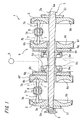
- FIG. 1 is a schematic diagram showing a variator part of a full toroidal continuously variable transmission which is a kind of a toroidal continuously variable transmission according to an embodiment of the present invention.
- This variator 1 is provided with an input shaft 3 which is driven to rotate by an output shaft 2 of an engine and input disks 5 are supported in the vicinity of both ends thereof.
- a concave curved raceway surface 5b is formed in one side of each input disk 5 and a spline hole 5a with a plurality of grooves is formed in an inner circumference thereof.
- the input disk 5 is joined to the input shaft 3 in an integrally rotatable manner by coupling the spline hole 5a with a spline shaft 3a provided in the input shaft 3. Furthermore, the movement of the respective input disks 5 in a direction of moving away from each other is regulated by an engagement ring 51 fixed to the input shaft 3.
- An output section 6 provided with output members 6a and output disks 6b which are supported by the output members 6a in an integrally rotatable manner is provided in the center of the input shaft 3 in the axial direction in a relatively rotatable manner with respect to the input shaft 3.
- a concave curved raceway surface 6c is formed in one side of the output disk 6b facing the raceway surface 5b of the input disk 5.
- Sprocket gears 6e which engage with a chain 6d are formed on the outer circumference of the output members 6a so that power is transmitted to the outside via the chain 6d.
- the output disk 6b is joined to the output member 6a in such a manner that the output disk 6b is allowed to inch in the axial direction, a gap 6g is provided on the back thereof and a backup plate 6h is arranged.
- the gap 6g is sealed by a casing 6f and a seal (not shown) and supplying a hydraulic pressure to this gap 6g from a hydraulic power source 9 puts force on the output disk 6b in the direction of the opposing input disk 5 and applies a predetermined terminal load thereto.
- the space between the raceway surface 5b of the input disk 5 and the raceway surface 6c of the output disk 6b facing each other is structured as a toroidal gap, this toroidal gap is supplied with a lubricant (traction oil) and three disk-shaped rollers 7 which rotate while making rolling/sliding contact with each raceway surface 5b, 6c via an oil film are arranged equiangularly on the circumference of a circle.
- the parts that contact the raceway surfaces 5b and 6c are outer surfaces 7b of the roller 7.
- Each roller 7 is supported by a carriage 8 in a rotatable manner such that an axis of rotation 7a thereof can be tilted.
- a drive force by a hydraulic pressure is applied to the carriage 8 in a direction crossing the surface of the sheet in FIG. 1.
- the both disks 5, 6b and the rollers 7 are rolling/sliding members which make rolling/sliding contact with each other and the rolling/sliding member according to the present invention is applied thereto.
- These rolling/sliding members are made of heat-resistant bearing steel.
- This heat-resistant bearing steel is adjusted to a composition containing alloy elements within a range satisfying C: not less than 0.8 wt% and not more than 1.5 wt%, Si: not less than 0.9 wt% and not more than 2.1 wt%, Mn: not less than 0.05 wt% and not more than 0.5 wt%, Cr: not less than 2 wt% and not more than 5 wt%, and Mo: not less than 0.05 wt% and not more than 0.5 wt% with the remainder being Fe and unavoidable impurities.
- the content of C when the content of C is less than 0.8 wt%, sufficient hardness may not be obtained after quenching. For this reason, the content of C needs to be not less than 0.8 wt%.
- the content of C when the content of C exceeds 1.5 wt%, toughness decreases and results in a decrease of strength, and therefore the content of C needs to be not more than 1.5 wt%.
- the content of C of the above described heat-resistant bearing steel is preferably not less than 0.9 wt% in the above described range.
- the content of C is preferably not more than 1.1 wt% in the above described range.
- a predetermined amount of Si needs to be contained for the purpose of suppressing decrease of the value of hardness when heated to not less than 300 °C, increasing tempering softening resistance and thereby increasing high-temperature strength.
- the content of Si is less than 0.9 wt%, the stability of retained austenite becomes insufficient and heat-resistance of the material becomes insufficient, and therefore the content of Si needs to be not less than 0.9 wt%.
- the content of Si exceeds 2.1 wt%, toughness decreases and results in a decrease of strength, and therefore the content of Si needs to be not more than 2.1 wt%.
- the content of Si of the above described heat-resistant bearing steel is preferably not more than 1.7 wt% in the above described range.
- Cr is an element which influences the formation of carbide and hardenability.
- the content of Cr is less than 2 wt%, the strength of the above described heat-resistant bearing steel decreases, and therefore the content of Cr needs to be not less than 2 wt%.
- the content of Cr exceeds 5 wt%, workability decreases due to an influence of carbide, and therefore the content of Cr needs to be not more than 5 wt%.
- the content of Mn needs to be not less than 0.05 wt%. Furthermore, when the content of Mn exceeds 0.5 wt%, machinability and toughness decrease, and therefore the content of Mn needs to be not more than 0.5 wt%. Furthermore, the content of Mn in the above described heat-resistant bearing steel is preferably not less than 0.4 wt% in the above described range.
- Mo is an element which improves the wear resistance through stabilization of residual carbide.
- the content of Mo being not less than 0.05 wt% increases hardenability, contributes to improvement of strength after quenching/tempering, improves wear resistance and rolling fatigue life through deposition of stable carbide, but since this operation and effect saturate at 0.5 wt%, the content of Mo is set to not more than 0.5 wt%.
- the content of Mo in the above described heat-resistant bearing steel is preferably not less than 0.3 wt% in the above described range.
- FIG. 2 shows manufacturing processes of the both disks 5, 6b, and the rollers 7.
- an intermediate material of the both disks 5, 6b, and the rollers 7 is formed out of a raw material made of the above described heat-resistant bearing steel through hot forging and cutting or the like (step S1).
- the intermediate material formed in step S1 is subjected to quenching and tempering at an austenitizing temperature of not less than 870 °C and not more than 950 °C and at an tempering temperature of not less than 200 °C and not more than 280 °C quenching/tempering process, step S2).
- the austenitizing temperature is lower than 870 °C, predetermined surface hardness may not be obtained.
- austenite crystal grains become rough during quenching and the strength of the rolling/sliding members after quenching and tempering may decrease.
- the austenitizing temperature is preferably set to not less than 870 °C and not more than 950 °C.
- the above described austenitizing temperature is preferably set to not more than 920 °C within the above described range. Setting the austenitizing temperature to not more than 920 °C can further reduce austenite crystal grains and thereby inhibit carbide from reducing and suppress the reduction of toughness and suppress the reduction of strength.
- step S2 quenching/tempering process
- step S3 surface hardening process
- This surface hardening process causes surface compression residual stress of the intermediate material to be not less than 700 MPa and not more than 1100 MPa and causes the amount of reduction of hardness when heated at 300 °C to be not more than 1 HRC.
- step S4 predetermined finishing
- the both disks 5, 6b, and the rollers 7 can thereby be obtained as finished products.
- the both disks 5, 6b, and the rollers 7 manufactured as shown above undergo the quenching/tempering process and the surface hardening process and surface hardness thereof is thereby set to not less than 60 HRC and not more than 64 HRC, the amount of retained austenite is set to not less than 10 wt% and not more than 20 wt%, surface compression residual stress thereof is set to not less than 700 MPa and not more than 1100 MPa by applying surface hardening to the surface through machining such as shot peening treatment and the amount of reduction of surface hardness when heated at 300°C can be set to not more than 1 HRC.
- the above described surface hardness and amount of retained austenite can be obtained by performing the above described quenching/tempering process on the heat-resistant bearing steel, but when surface hardness of the above described intermediate material is smaller than 60 HRC, the strength may fall short of the strength necessary for the rolling/sliding member, which increases the possibility that surface flaking may occur. Furthermore, when surface hardness of the raw material exceeds 64 HRC, toughness of the members decreases, which may cause the members to fracture or crack when used. Furthermore, when the content of retained austenite in steel reaches a certain amount, fatigue resistance against rolling and sliding improves.
- the amount of retained austenite is preferably set to not more than 20 wt% as described above.
- the heat-resistant bearing steel is subjected to the quenching/tempering process and compression residual stress is then applied through shot peening treatment, and this is attributable to the fact that machining (shot peening treatment) causes retained austenite to be transformed to martensite.
- the amount of retained austenite is preferably set to not less than 10 wt%.
- compression residual stress of the surface of the rolling/sliding members after shot peening treatment is set to not less than 700 MPa and not more than 1100 MPa, when this compression residual stress is less than 700 MPa, fatigue resistance may fall short of the fatigue resistance necessary for the rolling/sliding members.
- the compression residual stress is greater than 1100 MPa, excessive plastic deformation may occur on the surface of the intermediate material, making the rolling/sliding members brittle and this may cause surface flaking.
- the amount of reduction of surface hardness of the rolling/sliding member after shot peening treatment when heated at 300 °C is set to not more than 1 HRC, and when the amount of reduction of surface hardness is greater than 1 HRC, surface hardness of the rolling/sliding members decreases along with rolling and sliding, which may cause cracks on the surface.
- the temperature at the contact surface of a rolling/sliding member used for the toroidal continuously variable transmission is generally known to increase up to approximately 200 °C to 300 °C through rolling and sliding and the rolling/sliding member is always heated at around the above described temperature when the transmission is in operation.
- the surface of the rolling/sliding member set to predetermined surface hardness in the quenching/tempering process is tempered, which may cause the surface hardness to decrease considerably. That is, when the amount of reduction of surface hardness when heated at 300 °C is greater than 1 HRC, the reduction of surface hardness increases, the strength falls short of the strength necessary for the rolling/sliding member, which may produce cracks on the surface. On the other hand, as in the case of this embodiment, when the amount of reduction of surface hardness when heated at 300 °C is set to be smaller than 1 HRC, even when the surface is heated, it is possible to prevent the surface hardness from decreasing considerably.
- the full toroidal continuously variable transmission according to this embodiment is intended to synergistically increase fatigue resistance effectively and further increase durability by defining the composition of steel used for the rolling/sliding members (both disks 5, 6b, and rollers 7), above described compression residual stress value, surface hardness and amount of reduction of surface hardness by heating.
- the results of a test whereby the relationship between the above described values and durability in the rolling/sliding member was verified will be explained below.
- Table 1 below shows specifications of example products according to this embodiment and comparative example products used for this verification test.
- example products (1 to 6) and comparative example products (1 to 4) were used for the verification test by using steel adjusted to the predetermined composition shown in Table 1, conducting quenching and tempering processes under the heat treatment conditions shown in Table 1, then applying shot peening treatment to the surface under the following conditions and thereby conducting surface hardening.
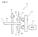
- FIG. 3 is a schematic diagram of a durability tester used for this verification test.
- a durability tester 10 has a disk 11 arranged so as to be rotatable around an axis of rotation 13, a pair of rollers 12 which hold sides 11a of the disk 11 in the vertical direction with a predetermined load and a motor M which drives the pair of rollers 12 via a gear box 14 so that the rollers 12 synchronously rotate in mutually opposite directions.
- the disk 11 is constructed so as to be driven to rotate with the torque transmitted from the pair of rollers 12 driven by the motor M and it is possible to reproduce a condition similar to that of the actual apparatus of transmitting the torque between an end face 12a of the roller 12 and the side 11 a of the disk 11 and making rolling/sliding contact.
- Table 2 also shows the measurement results of surface hardness and amount of retained austenite after a quenching/tempering process, surface hardness and amount of retained austenite, compression residual stress on the surface and amount of reduction of surface hardness after heating for two hours at 300 °C after shot peening treatment of products according to different embodiments and comparative examples.
- Table 2 shows the amount of reduction of surface hardness after heating as a difference in surface hardness before and after heating obtained by heating the respective example products and comparative example products which have been subjected to shot peening treatment to 300 °C, keeping those products in an atmospheric furnace or the like for two hours and then measuring surface hardness on the C scale of Rockwell hardness.
- Table 2 it is appreciated that the useful life in the verification test on the example products according to the present invention is approximately double that of the comparative products. From this result, it has been confirmed that the example products according to this embodiment have such high fatigue resistance to rolling and sliding that breakage like surface flaking is not produced for a long time and are provided with high durability.
- FIG. 4 is a graph showing a relationship between the amount of Si and the amount of Cr contained in steel of the respective example products and comparative example products.
- the horizontal axis shows a weight % value of Si in steel
- the vertical axis shows a weight % value of Cr in steel
- the example products are plotted with white outline circles and the comparative example products are plotted with black solid circles.
- the amount of Si in steel is set to 1 to 2 wt% and the amount of Cr is set to 2 to 5 wt%, and therefore they are plotted within the range shown by a dotted line H in the figure.
- the amount of Si is substantially 1 wt%, which satisfies the above described condition of the amount of Si but the amount of Cr is slightly lower than 2 wt%, which does not satisfy the above described condition of the amount of Cr.
- the amount of Cr is substantially 2 wt%, which satisfies the above described condition of the amount of Cr, but the amount of Si is 3 wt%, which does not satisfy the condition of the amount of Si.
- the rolling/sliding member needs to satisfy conditions for both the amount of Si and the amount of Cr in steel.
- the rolling/sliding member of the present invention uses steel containing the above described predetermined contents of Si, Cr, achieves predetermined surface hardness through quenching/tempering, applies the above described surface compression residual stress, and can thereby keep surface hardness necessary for the rolling/sliding member even when the surface of the rolling/sliding member is heated with heat accompanying rolling and sliding and suppress generation of surface cracks caused by a reduction of surface hardness.
- the toroidal continuously variable transmission according to this embodiment applies rolling/sliding members with enhanced fatigue resistance and higher durability, and can thereby further increase the durability. Furthermore, according to the method of manufacturing the rolling/sliding member of the above described embodiment, not only using the heat-resistant bearing steel but also including the quenching/tempering process and the surface hardening process can effectively increase fatigue resistance and obtain rolling/sliding members with higher durability.
- the rolling/sliding member of the present invention is not limited to the above described embodiment.
- the above described embodiment applies the rolling/sliding member according to the present invention to all the input/output disks and rollers of the toroidal continuously variable transmission, but it is also possible to apply the rolling/sliding member of the present invention to only the input/output disks and combine them with rollers according to other specifications using, for example, SUJ2.
- the above described embodiment has shown the full toroidal continuously variable transmission, but the present invention is also applicable to a toroidal continuously variable transmission in other modes such as a half toroidal type.
Landscapes
- Chemical & Material Sciences (AREA)
- Engineering & Computer Science (AREA)
- Mechanical Engineering (AREA)
- Materials Engineering (AREA)
- Metallurgy (AREA)
- Organic Chemistry (AREA)
- Crystallography & Structural Chemistry (AREA)
- Physics & Mathematics (AREA)
- Thermal Sciences (AREA)
- General Engineering & Computer Science (AREA)
- Heat Treatment Of Articles (AREA)
Abstract
Description
- The present invention relates to a rolling/sliding member used for a transmission of an automobile or the like, a toroidal continuously variable transmission using this rolling/sliding member and a method of manufacturing the rolling/sliding member.
- A toroidal continuously variable transmission is provided with an input disk and an output disk each having a concave curved raceway surface to be a roller raceway surface on a side thereof and a roller which makes rolling/sliding contact with the raceway surfaces of both disks facing each other under a lubricated and highpressure condition. The toroidal continuously variable transmission can transmit torque between the disks by means of traction between each disk and the roller and can increase/decrease the number of revolutions (change gear ratio) of the output disk with respect to the input disk with smooth motion which is different from motion of a conventional transmission by adjusting the position at which the roller contacts each disk.
- In the above described toroidal continuously variable transmission, rolling/sliding members which make rolling/sliding contact such as the input and output disks and roller make rolling/sliding contact with each other in a condition in which they are exposed to high temperature, high contact pressure and moreover shear stress which acts through traction during torque transmission, and they are therefore under extreme operating conditions. For this reason, high fatigue resistance is required so as to reduce the possibility of producing flaking caused by surface flaking and a structural variation with micro cracks or the like produced on the surface as starting points.
To meet such requirements, in manufacturing rolling/sliding members of a toroidal continuously variable transmission, there is a proposal of a technique as described inJapanese Patent Laid-Open No. 2004-218 715 - In the above described conventional example, compression residual stress applied to the surface increases fatigue resistance and can thereby suppress surface originated flaking. This makes it possible to prevent early damage on the surface and acquire a high degree of durability.
However, there is an increasing demand for a reduction of fuel consumption and downsizing of automobiles in recent years and there is also an increasing demand for a higher degree of durability of a transmission used for such automobiles to meet the demand for downsizing thereof. - It is an object of the present invention to provide a rolling/sliding member capable of achieving greater durability and a toroidal continuously variable transmission using this rolling/sliding member and a method of manufacturing the rolling/sliding member.
- In order to attain the above described object, the inventors have made every effort to research in pursuit of development of a rolling/sliding member capable of realizing greater durability. In the process, the inventors have conducted various experiments and research focusing on a reduction of surface hardness resulting from heat generation tempering (heating) due to rolling/sliding contact, which is one of causes for surface cracks. As a result, the inventors have come up with the present invention by discovering that especially the contents of Si, Cr contained in the raw material of a rolling/sliding member and compression residual stress of the surface have a great influence on the reduction of surface hardness due to heating.
- That is, the present invention is a rolling/sliding member used for a toroidal continuously variable transmission, wherein the rolling/sliding member is made of steel containing at least:
- C: not less than 0.8 wt% and not more than 1.5 wt%
- Si: not less than 0.9 wt% and not more than 2.1 wt%
- Cr: not less than 2 wt% and not more than 5 wt%,
- According to the rolling/sliding member in the above described construction, steel containing the above described predetermined amounts of Si and Cr is used, quenching and tempering are performed to thereby set predetermined surface hardness and the above described surface compression residual stress is added, and it is thereby possible to set the amount of reduction of surface hardness when heated at 300 °C to not more than 1 HRC.
The temperature of the contact surface of the rolling/sliding member used for the toroidal continuously variable transmission is known to generally increase to approximately 200 to 300°C through rolling/sliding thereof. In contrast, even when the surface of the rolling/sliding member is heated, the reduction of surface hardness is suppressed to not more than 1 HRC, and therefore even when the surface of the rolling/sliding member is heated by heat generation accompanying rolling and sliding, it is possible to suppress the reduction of surface hardness. Therefore, it is possible to keep surface hardness necessary for the rolling/sliding member and suppress generation of surface cracks originating from the reduction of surface hardness. In addition to compression residual stress applied to the surface, it is possible to effectively enhance fatigue resistance of the rolling/sliding member and obtain higher durability. - Furthermore, the amount of retained austenite before the surface hardening is preferably not less than 10 wt% and not more than 20 wt%.
When the amount of retained austenite exceeds 20 wt%, retained austenite is decomposed through heat generation accompanying rolling and sliding of the rolling/sliding member and surface flaking is more likely to occur as a consequence.
Since fatigue resistance to rolling and sliding generally improves by containing a certain amount of retained austenite in steel, it is possible to increase the fatigue resistance by setting the amount within the above described range without producing surface flaking or the like. - Furthermore, the above described rolling/sliding member preferably has an austenitizing temperature of not less than 870 °C and not more than 950 °C and an tempering temperature of not less than 200 °C and not more than 280 °C.
When the above described austenitizing temperature is lower than 870 °C, predetermined surface hardness may not be obtained. On the other hand, when the austenitizing temperature is higher than 950 °C, austenite crystal grains during quenching may become coarse and the strength of the rolling/sliding member after quenching and tempering may decrease. - Furthermore, the present invention is a method of manufacturing a rolling/sliding member used for a toroidal continuously variable transmission, comprising a quenching/tempering process of performing quenching/tempering on an intermediate material of the rolling/sliding member made of steel containing at least:
- C: not less than 0.8 wt% and not more than 1.5 wt%
- Si: not less than 0.9 wt% and not more than 2.1 wt%
- Cr: not less than 2 wt% and not more than 5 wt%,
- According to the method of manufacturing a rolling/sliding member in the above described construction, surface hardness is set to 60 HRC to 64 HRC and the amount of retained austenite is set to not less than 10 wt% and not more than 20 wt% by quenching and tempering an intermediate material made of steel with the above described predetermined contents of Si and Cr and this intermediate material is further subjected to surface hardening through machining, and it is thereby possible to apply surface compression residual stress within a range of not less than 700 MPa and not more than 1100 MPa and set the amount of reduction of surface hardness when heated at 300 °C to not more than 1 HRC.
The rolling/sliding member manufactured in this way can keep surface hardness necessary for the rolling/sliding member even when the surface of the rolling/sliding member is heated by heat generation accompanying rolling and sliding and suppress generation of surface cracks caused by the reduction of surface hardness. In addition to compression residual stress applied to the surface, it is further possible to effectively enhance fatigue resistance of the rolling/sliding member.
That is, according to the above described method of manufacturing a rolling/sliding member, it is possible to effectively increase fatigue resistance and obtain a rolling/sliding member having higher durability. - Furthermore, the present invention is a toroidal continuously variable transmission including an input disk having a concave curved raceway surface on a side, an output disk having a concave curved raceway surface facing the raceway surface of the input disk on a side and rollers which are sandwiched between raceway surfaces of the respective disks in a rotatable manner and transmit torque between the respective disks through rolling and sliding between the respective disks, wherein at least one of the input disk, output disk and rollers, which are rolling/sliding members, is the above described rolling/sliding member.
According to the toroidal continuously variable transmission in the above described construction, since each of the above described disks and rollers is the above described rolling/sliding member, it is possible to effectively increase fatigue resistance of these members and further enhance durability of the toroidal continuously variable transmission. -
- FIG. 1
- is a schematic diagram showing a variator part of a full toroidal continuously variable transmission which is a kind of a toroidal continuously variable transmission according to an embodiment of the present invention;
- FIG. 2
- shows manufacturing processes of both disks and the roller;
- FIG. 3
- is a schematic diagram of a durability tester used for a verification test; and
- FIG. 4
- is a graph showing a relationship between the amount of Si and the amount of Cr contained in steel of products according to different examples and comparative examples.
- Next, a preferred embodiment of the present invention will be explained with reference to the attached drawings. FIG. 1 is a schematic diagram showing a variator part of a full toroidal continuously variable transmission which is a kind of a toroidal continuously variable transmission according to an embodiment of the present invention. This
variator 1 is provided with aninput shaft 3 which is driven to rotate by anoutput shaft 2 of an engine andinput disks 5 are supported in the vicinity of both ends thereof. - A concave
curved raceway surface 5b is formed in one side of eachinput disk 5 and aspline hole 5a with a plurality of grooves is formed in an inner circumference thereof. Theinput disk 5 is joined to theinput shaft 3 in an integrally rotatable manner by coupling thespline hole 5a with aspline shaft 3a provided in theinput shaft 3. Furthermore, the movement of therespective input disks 5 in a direction of moving away from each other is regulated by anengagement ring 51 fixed to theinput shaft 3. - An
output section 6 provided withoutput members 6a andoutput disks 6b which are supported by theoutput members 6a in an integrally rotatable manner is provided in the center of theinput shaft 3 in the axial direction in a relatively rotatable manner with respect to theinput shaft 3. A concavecurved raceway surface 6c is formed in one side of theoutput disk 6b facing theraceway surface 5b of theinput disk 5. Sprocket gears 6e which engage with achain 6d are formed on the outer circumference of theoutput members 6a so that power is transmitted to the outside via thechain 6d. - The
output disk 6b is joined to theoutput member 6a in such a manner that theoutput disk 6b is allowed to inch in the axial direction, agap 6g is provided on the back thereof and abackup plate 6h is arranged. Thegap 6g is sealed by acasing 6f and a seal (not shown) and supplying a hydraulic pressure to thisgap 6g from ahydraulic power source 9 puts force on theoutput disk 6b in the direction of theopposing input disk 5 and applies a predetermined terminal load thereto. - The space between the
raceway surface 5b of theinput disk 5 and theraceway surface 6c of theoutput disk 6b facing each other is structured as a toroidal gap, this toroidal gap is supplied with a lubricant (traction oil) and three disk-shaped rollers 7 which rotate while making rolling/sliding contact with eachraceway surface
The parts that contact the raceway surfaces 5b and 6c areouter surfaces 7b of theroller 7. Eachroller 7 is supported by acarriage 8 in a rotatable manner such that an axis ofrotation 7a thereof can be tilted. A drive force by a hydraulic pressure is applied to thecarriage 8 in a direction crossing the surface of the sheet in FIG. 1. - In the
variator 1, when the pair ofinput disks 5 rotate, torque is transmitted from theinput disks 5 to theoutput disks 6b via the threerollers 7 on the left and right sides by a shear force of the oil film. Therollers 7 supported by thecarriage 8 tilt the axis ofrotation 7a to cancel unbalance between a reaction force produced in thecarriage 8 by transmitting the torque and the torque required to drive theoutput disk 6b. This causes the positions of therollers 7 to change as shown by two-dot dashed lines in the figure and causes the change gear ratio between the bothdisks - In the full toroidal continuously variable transmission in the above described construction, the both
disks rollers 7 are rolling/sliding members which make rolling/sliding contact with each other and the rolling/sliding member according to the present invention is applied thereto. These rolling/sliding members (bothdisks
This heat-resistant bearing steel is adjusted to a composition containing alloy elements within a range satisfying C: not less than 0.8 wt% and not more than 1.5 wt%, Si: not less than 0.9 wt% and not more than 2.1 wt%, Mn: not less than 0.05 wt% and not more than 0.5 wt%, Cr: not less than 2 wt% and not more than 5 wt%, and Mo: not less than 0.05 wt% and not more than 0.5 wt% with the remainder being Fe and unavoidable impurities. - In the above described heat-resistant bearing steel, when the content of C is less than 0.8 wt%, sufficient hardness may not be obtained after quenching. For this reason, the content of C needs to be not less than 0.8 wt%. On the other hand, when the content of C exceeds 1.5 wt%, toughness decreases and results in a decrease of strength, and therefore the content of C needs to be not more than 1.5 wt%.
Furthermore, the content of C of the above described heat-resistant bearing steel is preferably not less than 0.9 wt% in the above described range. Furthermore, the content of C is preferably not more than 1.1 wt% in the above described range. - Moreover, in the above described heat-resistant bearing steel, a predetermined amount of Si needs to be contained for the purpose of suppressing decrease of the value of hardness when heated to not less than 300 °C, increasing tempering softening resistance and thereby increasing high-temperature strength.
When the content of Si is less than 0.9 wt%, the stability of retained austenite becomes insufficient and heat-resistance of the material becomes insufficient, and therefore the content of Si needs to be not less than 0.9 wt%. Furthermore, when the content of Si exceeds 2.1 wt%, toughness decreases and results in a decrease of strength, and therefore the content of Si needs to be not more than 2.1 wt%.
Furthermore, the content of Si of the above described heat-resistant bearing steel is preferably not more than 1.7 wt% in the above described range. - In the above described heat-resistant bearing steel, Cr is an element which influences the formation of carbide and hardenability.
When the content of Cr is less than 2 wt%, the strength of the above described heat-resistant bearing steel decreases, and therefore the content of Cr needs to be not less than 2 wt%. When the content of Cr exceeds 5 wt%, workability decreases due to an influence of carbide, and therefore the content of Cr needs to be not more than 5 wt%. - In the above described heat-resistant bearing steel, since Mn improves hardenability of steel, secures sufficient hardness of steel and effectively acts on improvement of rolling fatigue life, the content of Mn needs to be not less than 0.05 wt%. Furthermore, when the content of Mn exceeds 0.5 wt%, machinability and toughness decrease, and therefore the content of Mn needs to be not more than 0.5 wt%.
Furthermore, the content of Mn in the above described heat-resistant bearing steel is preferably not less than 0.4 wt% in the above described range. - Mo is an element which improves the wear resistance through stabilization of residual carbide. The content of Mo being not less than 0.05 wt% increases hardenability, contributes to improvement of strength after quenching/tempering, improves wear resistance and rolling fatigue life through deposition of stable carbide, but since this operation and effect saturate at 0.5 wt%, the content of Mo is set to not more than 0.5 wt%.
Furthermore, the content of Mo in the above described heat-resistant bearing steel is preferably not less than 0.3 wt% in the above described range. - Next, a method of manufacturing the both
disks rollers 7 described above will be explained. FIG. 2 shows manufacturing processes of the bothdisks rollers 7. In the figure, an intermediate material of the bothdisks rollers 7 is formed out of a raw material made of the above described heat-resistant bearing steel through hot forging and cutting or the like (step S1).
The intermediate material formed in step S1 is subjected to quenching and tempering at an austenitizing temperature of not less than 870 °C and not more than 950 °C and at an tempering temperature of not less than 200 °C and not more than 280 °C quenching/tempering process, step S2). Through this quenching/tempering process, surface hardness of the intermediate material becomes not less than 60 HRC and not more than 64 HRC and the amount of retained austenite becomes not less than 10 wt% and not more than 20 wt%.
When the austenitizing temperature is lower than 870 °C, predetermined surface hardness may not be obtained. On the other hand, when it is higher than 950 °C, austenite crystal grains become rough during quenching and the strength of the rolling/sliding members after quenching and tempering may decrease. For this reason, the austenitizing temperature is preferably set to not less than 870 °C and not more than 950 °C. - Furthermore, the above described austenitizing temperature is preferably set to not more than 920 °C within the above described range. Setting the austenitizing temperature to not more than 920 °C can further reduce austenite crystal grains and thereby inhibit carbide from reducing and suppress the reduction of toughness and suppress the reduction of strength.
- Next, the intermediate material which has undergone step S2 (quenching/tempering process) is subjected to surface hardening through machining such as shot peening treatment (step S3, surface hardening process). This surface hardening process causes surface compression residual stress of the intermediate material to be not less than 700 MPa and not more than 1100 MPa and causes the amount of reduction of hardness when heated at 300 °C to be not more than 1 HRC.
The intermediate material which has undergone the surface hardening process is subjected to predetermined finishing (step S4) and the bothdisks rollers 7 can thereby be obtained as finished products. - The both
disks rollers 7 manufactured as shown above undergo the quenching/tempering process and the surface hardening process and surface hardness thereof is thereby set to not less than 60 HRC and not more than 64 HRC, the amount of retained austenite is set to not less than 10 wt% and not more than 20 wt%, surface compression residual stress thereof is set to not less than 700 MPa and not more than 1100 MPa by applying surface hardening to the surface through machining such as shot peening treatment and the amount of reduction of surface hardness when heated at 300°C can be set to not more than 1 HRC. - In this embodiment, the above described surface hardness and amount of retained austenite can be obtained by performing the above described quenching/tempering process on the heat-resistant bearing steel, but when surface hardness of the above described intermediate material is smaller than 60 HRC, the strength may fall short of the strength necessary for the rolling/sliding member, which increases the possibility that surface flaking may occur. Furthermore, when surface hardness of the raw material exceeds 64 HRC, toughness of the members decreases, which may cause the members to fracture or crack when used.
Furthermore, when the content of retained austenite in steel reaches a certain amount, fatigue resistance against rolling and sliding improves. However, when the amount of retained austenite is excessive, heat generated by rolling and sliding may cause retained austenite to decompose and increase the possibility that surface flaking may occur as a consequence, and therefore the amount of retained austenite is preferably set to not more than 20 wt% as described above.
Furthermore, in this embodiment, the heat-resistant bearing steel is subjected to the quenching/tempering process and compression residual stress is then applied through shot peening treatment, and this is attributable to the fact that machining (shot peening treatment) causes retained austenite to be transformed to martensite. For this reason, when the amount of retained austenite is too little, it is not possible to secure sufficient compression residual stress when subjected to machining, and therefore the amount of retained austenite is preferably set to not less than 10 wt%.
Furthermore, though compression residual stress of the surface of the rolling/sliding members after shot peening treatment is set to not less than 700 MPa and not more than 1100 MPa, when this compression residual stress is less than 700 MPa, fatigue resistance may fall short of the fatigue resistance necessary for the rolling/sliding members. On the other hand, when the compression residual stress is greater than 1100 MPa, excessive plastic deformation may occur on the surface of the intermediate material, making the rolling/sliding members brittle and this may cause surface flaking. - In this embodiment, the amount of reduction of surface hardness of the rolling/sliding member after shot peening treatment when heated at 300 °C is set to not more than 1 HRC, and when the amount of reduction of surface hardness is greater than 1 HRC, surface hardness of the rolling/sliding members decreases along with rolling and sliding, which may cause cracks on the surface.
This is because the temperature at the contact surface of a rolling/sliding member used for the toroidal continuously variable transmission is generally known to increase up to approximately 200 °C to 300 °C through rolling and sliding and the rolling/sliding member is always heated at around the above described temperature when the transmission is in operation. When heated at 200 °C to 300 °C in this way, the surface of the rolling/sliding member set to predetermined surface hardness in the quenching/tempering process is tempered, which may cause the surface hardness to decrease considerably.
That is, when the amount of reduction of surface hardness when heated at 300 °C is greater than 1 HRC, the reduction of surface hardness increases, the strength falls short of the strength necessary for the rolling/sliding member, which may produce cracks on the surface. On the other hand, as in the case of this embodiment, when the amount of reduction of surface hardness when heated at 300 °C is set to be smaller than 1 HRC, even when the surface is heated, it is possible to prevent the surface hardness from decreasing considerably. - The full toroidal continuously variable transmission according to this embodiment is intended to synergistically increase fatigue resistance effectively and further increase durability by defining the composition of steel used for the rolling/sliding members (both
disks - Table 1 below shows specifications of example products according to this embodiment and comparative example products used for this verification test.
-
Table. 1 Ingredient (wt%) Quenching temperature (°C) Temper i ng temperature (°C) C Si Cr Mn Mo Example product 1 1.02 1.48 2.01 0.45 0.42 860 280 Example product 21.05 0.98 3.49 0.43 0.43 900 220 Example product 30.98 1.53 3.52 0.46 0.42 880 220 Example product 41.01 1.02 4.98 0.44 0.45 920 200 Example product 50.99 1.49 4.99 0.45 0.42 940 220 Example product 60.97 2.02 3.47 0.46 0.43 890 250 Comparative Example product 10.99 0.98 1.86 0.43 0.44 860 250 Comparative Example product 20.98 3.02 2.01 0.45 0.42 860 300 Comparative Example product 31.01 0.25 1.46 0.44 0.43 840 200 Comparative Example product 41.04 2.98 5.48 0.44 0.44 970 260 - These example products (1 to 6) and comparative example products (1 to 4) were used for the verification test by using steel adjusted to the predetermined composition shown in Table 1, conducting quenching and tempering processes under the heat treatment conditions shown in Table 1, then applying shot peening treatment to the surface under the following conditions and thereby conducting surface hardening.
- The conditions of the above described shot peening treatment are as follows:
- (1) Model (scheme): Direct air compression scheme
- (2) Shot particles: RCW06PU (φ0.6 mm) approximately 830 HV
- (3) shot peening pressure: 0.49 MPa
- (4) Number of revolutions of table (number of revolutions of sample): 12 rpm
- (5) Nozzle diameter: φ6 mm
- (6) Nozzle-sample distance: 100 mm
- (7) Arc height: 0.64 mmA
- (8) Coverage: 200% (target value)
- FIG. 3 is a schematic diagram of a durability tester used for this verification test. In FIG. 3, a
durability tester 10 has adisk 11 arranged so as to be rotatable around an axis ofrotation 13, a pair ofrollers 12 which holdsides 11a of thedisk 11 in the vertical direction with a predetermined load and a motor M which drives the pair ofrollers 12 via agear box 14 so that therollers 12 synchronously rotate in mutually opposite directions. Thedisk 11 is constructed so as to be driven to rotate with the torque transmitted from the pair ofrollers 12 driven by the motor M and it is possible to reproduce a condition similar to that of the actual apparatus of transmitting the torque between anend face 12a of theroller 12 and theside 11 a of thedisk 11 and making rolling/sliding contact. - In this verification test, the above described example products and comparative example products were applied to the
disk 11 of thedurability tester 10, a time until rolling and sliding with theroller 12 produced breakage on theside 11a of thedisk 11 was measured as useful life and durability of thedisk 11 was evaluated based on the useful life.
The test conditions of the above describeddurability tester 10 were set as follows: - (1) Rotation speed of roller: 3000 rpm
- (2) Slip ratio between roller and disk: 14%
- (3) Maximum contact pressure: 4.2 GPa
- (4) Lubricant: Traction oil for toroidal continuously variable transmission
- (5) Oil film parameter (A): 1.8
-
Table. 2 After quenching/tempering After shot peening (after surface hardening) Useful life (h) Surface hardness (HRC) Amount of residual austenite (wt%) Surface hardness (HRC) Amount of residual austenite (wt%) Amount of reduction of surface hardness after heating (HRC) Maximum value of residual compression stress (MPa) Example product 161.2 12 62.7 7 0.6 950 900 Example product 260.8 19 63 10 0.4 1090 1150 Example product 360.9 13 63.6 5 0.3 1040 1020 Example product 461.3 15 63 10 0.5 750 1200 Example product 561.5 17 62.9 11 0.4 980 986 Example product 661.3 14 63.5 5 0.3 1020 1080 Comparative Example product 161 10 61.5 8 1.1 200 452 Comparative Example product 261 11 62 7 0.5 500 420 Comparative Example product 359 4 62.8 1 2.5 1320 300 Comparative Example product 461 21 61 21 0.3 150 484 - In addition to the useful life measured by the above described durability tester, Table 2 also shows the measurement results of surface hardness and amount of retained austenite after a quenching/tempering process, surface hardness and amount of retained austenite, compression residual stress on the surface and amount of reduction of surface hardness after heating for two hours at 300 °C after shot peening treatment of products according to different embodiments and comparative examples.
- Table 2 shows the amount of reduction of surface hardness after heating as a difference in surface hardness before and after heating obtained by heating the respective example products and comparative example products which have been subjected to shot peening treatment to 300 °C, keeping those products in an atmospheric furnace or the like for two hours and then measuring surface hardness on the C scale of Rockwell hardness.
As is clear from Table 2, it is appreciated that the useful life in the verification test on the example products according to the present invention is approximately double that of the comparative products. From this result, it has been confirmed that the example products according to this embodiment have such high fatigue resistance to rolling and sliding that breakage like surface flaking is not produced for a long time and are provided with high durability. - FIG. 4 is a graph showing a relationship between the amount of Si and the amount of Cr contained in steel of the respective example products and comparative example products. In FIG. 4, the horizontal axis shows a weight % value of Si in steel, the vertical axis shows a weight % value of Cr in steel, and the example products are plotted with white outline circles and the comparative example products are plotted with black solid circles.
- In the Figure, in the case of the example products, the amount of Si in steel is set to 1 to 2 wt% and the amount of Cr is set to 2 to 5 wt%, and therefore they are plotted within the range shown by a dotted line H in the figure. On the other hand, in the case of the comparative example products, for example, with a circle M1 in the figure (comparative example product 1), the amount of Si is substantially 1 wt%, which satisfies the above described condition of the amount of Si but the amount of Cr is slightly lower than 2 wt%, which does not satisfy the above described condition of the amount of Cr.
Furthermore, with a circle M2 in the figure (comparative example product 2), the amount of Cr is substantially 2 wt%, which satisfies the above described condition of the amount of Cr, but the amount of Si is 3 wt%, which does not satisfy the condition of the amount of Si. In this way, it is understandable that the rolling/sliding member needs to satisfy conditions for both the amount of Si and the amount of Cr in steel. - As is evident from the above described results of the verification test, the rolling/sliding member of the present invention uses steel containing the above described predetermined contents of Si, Cr, achieves predetermined surface hardness through quenching/tempering, applies the above described surface compression residual stress, and can thereby keep surface hardness necessary for the rolling/sliding member even when the surface of the rolling/sliding member is heated with heat accompanying rolling and sliding and suppress generation of surface cracks caused by a reduction of surface hardness. In addition to the effect of improving fatigue resistance due to surface compression residual stress, it is also possible to more effectively increase fatigue resistance of the rolling/sliding member and achieve higher durability.
- This result shows that the effects become conspicuous in a full toroidal continuously variable transmission whose contact part between the roller and the disk is accompanied by large amount of spin and which is put under difficult contact conditions.
That is, the toroidal continuously variable transmission according to this embodiment applies rolling/sliding members with enhanced fatigue resistance and higher durability, and can thereby further increase the durability.
Furthermore, according to the method of manufacturing the rolling/sliding member of the above described embodiment, not only using the heat-resistant bearing steel but also including the quenching/tempering process and the surface hardening process can effectively increase fatigue resistance and obtain rolling/sliding members with higher durability. - The rolling/sliding member of the present invention is not limited to the above described embodiment. For example, the above described embodiment applies the rolling/sliding member according to the present invention to all the input/output disks and rollers of the toroidal continuously variable transmission, but it is also possible to apply the rolling/sliding member of the present invention to only the input/output disks and combine them with rollers according to other specifications using, for example, SUJ2.
Furthermore, the above described embodiment has shown the full toroidal continuously variable transmission, but the present invention is also applicable to a toroidal continuously variable transmission in other modes such as a half toroidal type.
Claims (5)
- A rolling/sliding member used for a toroidal continuously variable transmission, wherein the rolling/sliding member is made of steel containing at least:C: not less than 0.8 wt% and not more than 1.5 wt%,Si: not less than 0.9 wt% and not more than 2.1 wt%,Cr: not less than 2 wt% and not more than 5 wt%,wherein by applying surface hardening through machining to a surface whose surface hardness is set to not less than 60 HRC and not more than 64 HRC through quenching/tempering, surface compression residual stress thereof is set to not less than 700 MPa and not more than 1100 MPa, and the amount of reduction of surface hardness when heated at 300 °C is not more than 1 HRC.
- The rolling/sliding member according to claim 1,
wherein the amount of retained austenite before the surface hardening is not less than 10 wt% and not more than 20 wt%. - The rolling/sliding member according to claim 1 or 2,
wherein the austenitizing temperature is not less than 870 °C and not more than 950 °C and the tempering temperature is not less than 200 °C and not more than 280 °C. - A method of manufacturing a rolling/sliding member used for a toroidal continuously variable transmission, comprising the following steps:- a quenching/tempering process of performing quenching/tempering on an intermediate material of the rolling/sliding member made of steel containing at least:C: not less than 0.8 wt% and not more than 1.5 wt%,Si: not less than 0.9 wt% and not more than 2.1 wt%,Cr: not less than 2 wt% and not more than 5 wt%,at an austenitizing temperature of not less than 870 °C and not more than 950 °C and a tempering temperature of not less than 200 °C and not more than 280 °C to thereby set the surface hardness of the intermediate material to not less than 60 HRC and not more than 64 HRC and the amount of retained austenite to not less than 10 wt% and not more than 20 wt%; and- a surface hardening process of applying surface hardening through machining to the intermediate material which has undergone the quenching/tempering process, thereby setting the surface compression residual stress of the intermediate material to not less than 700 MPa and not more than 1100 MPa and setting the amount of reduction of the surface hardness to not more than 1 HRC when heated at 300 °C.
- A toroidal continuously variable transmission (1) comprising:- an input disk (5) having a concave curved raceway surface (5b) on a side;- an output disk (6b) having a concave curved raceway surface (6c) facing the raceway surface (5b) of the input disk (5) on a side; and- rollers (7) which are sandwiched between raceway surfaces (5b, 6c) of the respective disks (5, 6b) in a rotatable manner and transmit torque between the respective disk (5, 6b) through rolling and sliding between the respective disks (5, 6b),- wherein at least one of the input disk (5), the output disk (6b) and the rollers (7), which are rolling/sliding members, is the rolling/sliding member according to any of claims 1 to 3.
Applications Claiming Priority (1)
| Application Number | Priority Date | Filing Date | Title |
|---|---|---|---|
| JP2006052856 | 2006-02-28 |
Publications (2)
| Publication Number | Publication Date |
|---|---|
| EP1826460A1 true EP1826460A1 (en) | 2007-08-29 |
| EP1826460B1 EP1826460B1 (en) | 2009-04-08 |
Family
ID=38180090
Family Applications (1)
| Application Number | Title | Priority Date | Filing Date |
|---|---|---|---|
| EP07004192A Ceased EP1826460B1 (en) | 2006-02-28 | 2007-02-28 | Manufacturing method for an input disc, output disc and power roller of a toroidal continuously variable transmission |
Country Status (3)
| Country | Link |
|---|---|
| US (1) | US20070204940A1 (en) |
| EP (1) | EP1826460B1 (en) |
| DE (1) | DE602007000826D1 (en) |
Cited By (4)
| Publication number | Priority date | Publication date | Assignee | Title |
|---|---|---|---|---|
| US10145387B2 (en) | 2015-05-19 | 2018-12-04 | Rolls-Royce Plc | Compressor tip injector |
| US10221926B2 (en) | 2012-01-10 | 2019-03-05 | Allison Transmission, Inc. | Continuously variable toroidal transmission |
| US10371059B2 (en) | 2014-12-11 | 2019-08-06 | Rolls-Royce Plc | Cabin blower system |
| US10533645B2 (en) | 2012-01-23 | 2020-01-14 | Allison Transmission, Inc. | Dual-cavity toroidal variator |
Families Citing this family (4)
| Publication number | Priority date | Publication date | Assignee | Title |
|---|---|---|---|---|
| JP5682161B2 (en) * | 2009-08-10 | 2015-03-11 | 株式会社ジェイテクト | Manufacturing method of rolling sliding member |
| EP2486306B1 (en) | 2009-10-08 | 2017-07-26 | Ultimate Transmissions Pty Ltd | Full toroidal traction drive |
| US9458917B2 (en) * | 2011-04-18 | 2016-10-04 | Transmission Cvtcorp Inc. | Continuously variable transmission provided with a roller parking zone |
| CN109681615A (en) * | 2019-01-07 | 2019-04-26 | 中南大学 | A kind of detachable Multi-stage transmission gear-box |
Citations (4)
| Publication number | Priority date | Publication date | Assignee | Title |
|---|---|---|---|---|
| JPH03253542A (en) * | 1990-03-01 | 1991-11-12 | Kawasaki Steel Corp | Heat resistant bearing steel |
| US20030013574A1 (en) | 2001-07-10 | 2003-01-16 | Yasuharu Misada | Toroidal continuously variable transmission |
| JP2004218715A (en) * | 2003-01-14 | 2004-08-05 | Koyo Seiko Co Ltd | Toroidal type continuously variable transmission |
| WO2006041184A1 (en) | 2004-10-15 | 2006-04-20 | Jtekt Corporation | Roll/slide member, toroidal continuously variable transmission utilizing the same, and process for producing roll/slide member |
Family Cites Families (2)
| Publication number | Priority date | Publication date | Assignee | Title |
|---|---|---|---|---|
| GB2278127B (en) * | 1993-05-13 | 1995-11-08 | Nsk Ltd | Rolling bearing |
| JP4075492B2 (en) * | 2002-07-11 | 2008-04-16 | 株式会社ジェイテクト | Method for manufacturing torque transmitting member of toroidal type continuously variable transmission |
-
2007
- 2007-02-27 US US11/710,950 patent/US20070204940A1/en not_active Abandoned
- 2007-02-28 EP EP07004192A patent/EP1826460B1/en not_active Ceased
- 2007-02-28 DE DE602007000826T patent/DE602007000826D1/en active Active
Patent Citations (4)
| Publication number | Priority date | Publication date | Assignee | Title |
|---|---|---|---|---|
| JPH03253542A (en) * | 1990-03-01 | 1991-11-12 | Kawasaki Steel Corp | Heat resistant bearing steel |
| US20030013574A1 (en) | 2001-07-10 | 2003-01-16 | Yasuharu Misada | Toroidal continuously variable transmission |
| JP2004218715A (en) * | 2003-01-14 | 2004-08-05 | Koyo Seiko Co Ltd | Toroidal type continuously variable transmission |
| WO2006041184A1 (en) | 2004-10-15 | 2006-04-20 | Jtekt Corporation | Roll/slide member, toroidal continuously variable transmission utilizing the same, and process for producing roll/slide member |
Cited By (4)
| Publication number | Priority date | Publication date | Assignee | Title |
|---|---|---|---|---|
| US10221926B2 (en) | 2012-01-10 | 2019-03-05 | Allison Transmission, Inc. | Continuously variable toroidal transmission |
| US10533645B2 (en) | 2012-01-23 | 2020-01-14 | Allison Transmission, Inc. | Dual-cavity toroidal variator |
| US10371059B2 (en) | 2014-12-11 | 2019-08-06 | Rolls-Royce Plc | Cabin blower system |
| US10145387B2 (en) | 2015-05-19 | 2018-12-04 | Rolls-Royce Plc | Compressor tip injector |
Also Published As
| Publication number | Publication date |
|---|---|
| US20070204940A1 (en) | 2007-09-06 |
| EP1826460B1 (en) | 2009-04-08 |
| DE602007000826D1 (en) | 2009-05-20 |
Similar Documents
| Publication | Publication Date | Title |
|---|---|---|
| EP1826460B1 (en) | Manufacturing method for an input disc, output disc and power roller of a toroidal continuously variable transmission | |
| US6440232B1 (en) | Toroidal-type continuously variable transmission | |
| JP3995904B2 (en) | Method for producing inner ring for constant velocity joint excellent in workability and strength | |
| JPH07242994A (en) | Steel for gears with excellent tooth surface strength, gears, and method for manufacturing gears | |
| JPH0810015B2 (en) | Rolling bearing | |
| US6066068A (en) | Toroidal type continuously variable transmission | |
| US8118953B2 (en) | Method for producing steel part having long rolling contact fatigue life | |
| EP1258657B1 (en) | Toroidal continuously variable transmission and method of manufacturing the transmission | |
| EP1400606B1 (en) | Method of carburizing a bearing steel to produce a roller member | |
| JP4731945B2 (en) | Constant velocity universal joint, cage for constant velocity universal joint, and manufacturing method thereof | |
| US20230304528A1 (en) | Crankshaft | |
| US6780139B2 (en) | Toroidal continuously variable transmission | |
| EP1312694B1 (en) | Rolling, sliding part and process for producing same | |
| EP1452610A1 (en) | Rolling, sliding part and process for producing same | |
| EP1348775B1 (en) | Toroidal continuously variable transmission | |
| JPH11347673A (en) | Rolling bearing and method of manufacturing the same | |
| JP4572797B2 (en) | V-belt type continuously variable transmission pulley disk and manufacturing method thereof | |
| EP1811052A1 (en) | Roll/slide member, toroidal continuously variable transmission utilizing the same, and process for producing roll/slide member | |
| JP4100072B2 (en) | Full toroidal continuously variable transmission | |
| JPH02209452A (en) | Steel for rolling parts and rolling parts using the same | |
| JP6410612B2 (en) | Nitriding member and friction transmission using the same | |
| JP2007262572A (en) | Rolling sliding member, toroidal continuously variable transmission using the same, and method of manufacturing rolling sliding member | |
| JP2018200109A (en) | Tripod-type constant velocity universal joint | |
| JP4559276B2 (en) | Cage for constant velocity universal joint | |
| JPH08174340A (en) | Machine structural component excellent in surface fatigue strength and method for manufacturing the same |
Legal Events
| Date | Code | Title | Description |
|---|---|---|---|
| PUAI | Public reference made under article 153(3) epc to a published international application that has entered the european phase |
Free format text: ORIGINAL CODE: 0009012 |
|
| AK | Designated contracting states |
Kind code of ref document: A1 Designated state(s): AT BE BG CH CY CZ DE DK EE ES FI FR GB GR HU IE IS IT LI LT LU LV MC NL PL PT RO SE SI SK TR |
|
| AX | Request for extension of the european patent |
Extension state: AL BA HR MK YU |
|
| 17P | Request for examination filed |
Effective date: 20080228 |
|
| 17Q | First examination report despatched |
Effective date: 20080404 |
|
| AKX | Designation fees paid |
Designated state(s): DE FR |
|
| GRAP | Despatch of communication of intention to grant a patent |
Free format text: ORIGINAL CODE: EPIDOSNIGR1 |
|
| GRAS | Grant fee paid |
Free format text: ORIGINAL CODE: EPIDOSNIGR3 |
|
| GRAA | (expected) grant |
Free format text: ORIGINAL CODE: 0009210 |
|
| AK | Designated contracting states |
Kind code of ref document: B1 Designated state(s): DE FR |
|
| REF | Corresponds to: |
Ref document number: 602007000826 Country of ref document: DE Date of ref document: 20090520 Kind code of ref document: P |
|
| PLBE | No opposition filed within time limit |
Free format text: ORIGINAL CODE: 0009261 |
|
| STAA | Information on the status of an ep patent application or granted ep patent |
Free format text: STATUS: NO OPPOSITION FILED WITHIN TIME LIMIT |
|
| 26N | No opposition filed |
Effective date: 20100111 |
|
| REG | Reference to a national code |
Ref country code: FR Ref legal event code: PLFP Year of fee payment: 10 |
|
| REG | Reference to a national code |
Ref country code: FR Ref legal event code: PLFP Year of fee payment: 11 |
|
| REG | Reference to a national code |
Ref country code: FR Ref legal event code: PLFP Year of fee payment: 12 |
|
| PGFP | Annual fee paid to national office [announced via postgrant information from national office to epo] |
Ref country code: DE Payment date: 20200218 Year of fee payment: 14 |
|
| PGFP | Annual fee paid to national office [announced via postgrant information from national office to epo] |
Ref country code: FR Payment date: 20200113 Year of fee payment: 14 |
|
| REG | Reference to a national code |
Ref country code: DE Ref legal event code: R119 Ref document number: 602007000826 Country of ref document: DE |
|
| PG25 | Lapsed in a contracting state [announced via postgrant information from national office to epo] |
Ref country code: FR Free format text: LAPSE BECAUSE OF NON-PAYMENT OF DUE FEES Effective date: 20210228 Ref country code: DE Free format text: LAPSE BECAUSE OF NON-PAYMENT OF DUE FEES Effective date: 20210901 |