EP1826006A1 - Driving method of ink-jet printer and it's driving apparatus - Google Patents
Driving method of ink-jet printer and it's driving apparatus Download PDFInfo
- Publication number
- EP1826006A1 EP1826006A1 EP06113418A EP06113418A EP1826006A1 EP 1826006 A1 EP1826006 A1 EP 1826006A1 EP 06113418 A EP06113418 A EP 06113418A EP 06113418 A EP06113418 A EP 06113418A EP 1826006 A1 EP1826006 A1 EP 1826006A1
- Authority
- EP
- European Patent Office
- Prior art keywords
- printing
- head
- pitch
- time division
- groups
- Prior art date
- Legal status (The legal status is an assumption and is not a legal conclusion. Google has not performed a legal analysis and makes no representation as to the accuracy of the status listed.)
- Ceased
Links
Images



Classifications
-
- B—PERFORMING OPERATIONS; TRANSPORTING
- B41—PRINTING; LINING MACHINES; TYPEWRITERS; STAMPS
- B41J—TYPEWRITERS; SELECTIVE PRINTING MECHANISMS, i.e. MECHANISMS PRINTING OTHERWISE THAN FROM A FORME; CORRECTION OF TYPOGRAPHICAL ERRORS
- B41J2/00—Typewriters or selective printing mechanisms characterised by the printing or marking process for which they are designed
- B41J2/005—Typewriters or selective printing mechanisms characterised by the printing or marking process for which they are designed characterised by bringing liquid or particles selectively into contact with a printing material
- B41J2/01—Ink jet
- B41J2/015—Ink jet characterised by the jet generation process
- B41J2/04—Ink jet characterised by the jet generation process generating single droplets or particles on demand
- B41J2/045—Ink jet characterised by the jet generation process generating single droplets or particles on demand by pressure, e.g. electromechanical transducers
- B41J2/04501—Control methods or devices therefor, e.g. driver circuits, control circuits
- B41J2/04586—Control methods or devices therefor, e.g. driver circuits, control circuits controlling heads of a type not covered by groups B41J2/04575 - B41J2/04585, or of an undefined type
-
- B—PERFORMING OPERATIONS; TRANSPORTING
- B41—PRINTING; LINING MACHINES; TYPEWRITERS; STAMPS
- B41J—TYPEWRITERS; SELECTIVE PRINTING MECHANISMS, i.e. MECHANISMS PRINTING OTHERWISE THAN FROM A FORME; CORRECTION OF TYPOGRAPHICAL ERRORS
- B41J2/00—Typewriters or selective printing mechanisms characterised by the printing or marking process for which they are designed
- B41J2/005—Typewriters or selective printing mechanisms characterised by the printing or marking process for which they are designed characterised by bringing liquid or particles selectively into contact with a printing material
- B41J2/01—Ink jet
- B41J2/015—Ink jet characterised by the jet generation process
- B41J2/04—Ink jet characterised by the jet generation process generating single droplets or particles on demand
- B41J2/045—Ink jet characterised by the jet generation process generating single droplets or particles on demand by pressure, e.g. electromechanical transducers
- B41J2/04501—Control methods or devices therefor, e.g. driver circuits, control circuits
- B41J2/04543—Block driving
Definitions
- the present invention relates to a driving method of an ink jet printer and its driving apparatus.
- a printing is made in a predetermined head drive frequency with a relative head/medium speed set to a predetermined speed.
- a positional difference of nozzle groups corresponding to three divisions ceases to exist and, as shown in FIG. 8A, a printing is made in one line at a predetermined pitch in a nozzle direction.
- a printing is made in one line with the use of a plurality of nozzles and, by doing so, the printer is driven in a fashion less prominent in "print drops" and less "banding" resulting from a head-caused print variation.
- the "banding" means a nonuniform concentration caused by a white line emerging on a recording medium due to the non-jetting of an ink from some nozzle as well as by the misdirection caused by some nozzle.
- a printing is made by alternately using one half number of nozzles for each column and, by doing so, a printing is made a plurality of numbers as shown in FIG. 7A.
- reference numeral 11 shows a printing head.
- the nozzles 12 are provided in a zigzag fashion on a nozzle surface of the printing head 11. Those nozzles 12 are sequentially grouped in an A ⁇ B ⁇ C order from near the moving direction of the printing head 11.
- An Xab pitch is provided between the group A and the group B and an Xbc pitch between the group B and the group C.
- a printing is made in an order of n-2, n-1, n, n+1, n+2 columns.
- This printing is made in a sequential order of groups A, B, C for each column in a state to jet an ink from those nozzles belonging to the group.
- a printing is made at A1 belonging to group A, with no ink jetted from B2 due to no print data involved under group B, a printing is made at C1 under group C.
- no ink is jetted at A2 due to no print data involved under group A and a printing is made at B1 under group B and no ink is jetted at C2 due to no print data under group C.
- n-1 column For the n-1 column, a printing is made at B11 under group B, at A12 under group A and at C12 under group C. In the n-1 column, a printing is made at B11 under group B, at A12 under group A and at C12 under group C. In the n-1 column, no ink is jetted from the rest due to no print data involved.
- a printing was done using the relative speed of the head and recording medium as a predetermined speed. Since no half number of nozzles are not used for each column, it may be said that no effective use can be expected for the head.
- FIG. 9A shows a printing head.
- a printing head driving method using a printer head configured to effect a three time division so as not to simultaneously print an adjacent channel and means for receiving print data corresponding to each time division and printing it, the printer head being so constructed that, with the respective time division groups given as A, B, C, the head and printing medium are moved at predetermined speeds and, with the sequential drive order given as A, B, C, a printing result emerges as one row in a nozzle direction at a predetermined pitch to a relative moving direction of the head and printing medium, the method comprising a step of effecting a driving in a sequential drive order including C, B, A with the relative driving speed of the head and printing medium set double its speed and a step of receiving print data corresponding to each division and making a printing so that a printing result in a relative moving direction emerges at a pitch double that predetermined pitch and a printing result of the group A, C nozzles and B nozzles emerges in a state displace by a predetermined pitch.
- reference numeral 21 shows a printing head allowing three time divisions to be achieved without any simultaneous printing on an adjacent channel.
- the printing head 21 is mounted on a carriage 22.
- the control of the printing head 21 and carriage 22 is done by a controller 23.
- the carriage 22 Under the control of the controller 23, the carriage 22 is moved in right and left directions as indicated by an arrow a and a printing medium 24, while being conveyed in a direction (arrow b) perpendicular to the operation direction of the carriage 22, is printed so that an image is formed on it.
- reference numeral 31 shows a host computer. To this host computer 31 is connected the controller 23.
- the controller 23 comprises a CPU 41, a memory 42, a FIFO memory 43 and a GA (gate array) 44. From the FIFO memory 43 and GA 44, a head control signal and print data are sent to a head driving circuit 45.
- the head driving circuit 45 is provided in the controller 23. A detailed arrangement of the head driving circuit 45 is shown in FIG. 3.
- the print data is such as to allow data corresponding to a few lines to be sent from the host computer 31 to a printer 32.
- the thus sent print data is written into a memory 42 through the CPU 41 and GA 44.
- the print data written into the memory 42 is converted to a form shown in FIG. 4 and stored into the FIFO memory 43.
- nozzles are provided in a zigzag array on the printing head 21. As shown in FIG. 7, the nozzles are divided into three groups (A, B, C) and driven in a divided way.
- (n+1) st line data is stored for the group A data, (n)th line data for the group B data, and (n-1)th line data for the group C data (See FIG. 4).
- the print data which is output from the FIFO memory 43, as shown in FIG. 5C is stored in the shift register (S/R) 51 shown in FIG. 3 by a shift clock shown in FIG. 5B.
- S/R shift register
- the next print data is converted and stored in the FIFO memory 43.
- a latch signal shown in FIG. 5A is input to a latch circuit 52
- the data of the shift register 51 is latched to the latch circuit 52.
- the data stored in the FIFO memory 43 is stored in the shift register 51 by a shift clock.
- a first timing signal (FIG. 5D) is input to an output control circuit 53.
- a drive waveform generating circuit 54 outputs a drive waveform (FIG. 5E) to a corresponding group C nozzle. By doing so, an ink is jetted from the group C nozzle to effect a printing.
- a second timing signal is input to the output control circuit 53.
- the second timing signal (FIG. 5D) is input to the output control circuit 53
- the drive waveform generating circuit 54 outputs a drive waveform (FIG. 5E) to a corresponding group B nozzle. By doing so, an ink is jetted from the group B nozzle to effect a printing.
- a third timing signal is input to an output control circuit 53.
- the drive waveform generating circuit 54 outputs a drive waveform (FIG. 5E) to a corresponding group A nozzle. By doing so, an ink is jetted from the group A nozzle to effect a printing.
- an ink is jetted in a sequential order of group A nozzle ⁇ group B nozzle ⁇ group C nozzle.
- the relative speed of the printing medium 24 and printing head 21 is 16 ips (406 mm/s)
- the image resolution of the printing head 21 in a moving direction is 300 dpi
- the dot-to-dot drive frequency is 4800 Hz.
- a printer is driven at 4800 ⁇ 14400 Hz at the respective group nozzle intervals and, by doing so, respective dots are deposited on a 300 dpi grid array.
- printer is driven at a reverse order of the groups C ⁇ B ⁇ A instead of the order of A ⁇ B ⁇ C.
- the printing interval between respective nozzles of the groups A, B, C becomes 150 dpi and a printing is made with the groups A and B and the groups C and B displaced 300 dpi in a moving direction.
- a printing is effected in a sequence of a dot C10 at the group C nozzle, a dot B30 at the group B nozzle and a dot A40 at the group A nozzle.
- a printing is made with a group B nozzle dot B20 at an n-1 column, and a group A nozzle dot A10 and group C nozzle dot C10 at the n-1 column.
- the second printing is made by shifting the printing head 21 by an interval of 3Y ⁇ m (m is an integer not less than 0) (dpi) toward a direction perpendicular to a moving direction of the printing head 21. Printing is performed with the nozzles shifted by a pitch x in the conveying direction with respect to the first printing.
- one line can be comprised of different nozzles.
- the present invention is not restricted to this system. If, for example, nozzles are arranged in a displaced fashion as shown in FIG. 7B and respective nozzle groups are driven in a time division fashion, the present invention can be applied to it.
Landscapes
- Ink Jet (AREA)
Abstract
Description
- The present invention relates to a driving method of an ink jet printer and its driving apparatus.
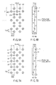
- Where a printer head as shown in FIG. 8B is driven in three-time division fashion, a printing is made in a predetermined head drive frequency with a relative head/medium speed set to a predetermined speed. By doing so, a positional difference of nozzle groups corresponding to three divisions ceases to exist and, as shown in FIG. 8A, a printing is made in one line at a predetermined pitch in a nozzle direction.
- Generally, in a serial printer, a printing is made in one line with the use of a plurality of nozzles and, by doing so, the printer is driven in a fashion less prominent in "print drops" and less "banding" resulting from a head-caused print variation. Here, the "banding" means a nonuniform concentration caused by a white line emerging on a recording medium due to the non-jetting of an ink from some nozzle as well as by the misdirection caused by some nozzle. In this case, it is known that, in the prior art technique, a printing is made by alternately using one half number of nozzles for each column and, by doing so, a printing is made a plurality of numbers as shown in FIG. 7A.
- In FIG. 7B,
reference numeral 11 shows a printing head. Thenozzles 12 are provided in a zigzag fashion on a nozzle surface of theprinting head 11. Thosenozzles 12 are sequentially grouped in an A → B → C order from near the moving direction of theprinting head 11. An Xab pitch is provided between the group A and the group B and an Xbc pitch between the group B and the group C. - As shown in FIG. 7A, a printing is made in an order of n-2, n-1, n, n+1, n+2 columns.
- This printing is made in a sequential order of groups A, B, C for each column in a state to jet an ink from those nozzles belonging to the group. For the n-2 column, a printing is made at A1 belonging to group A, with no ink jetted from B2 due to no print data involved under group B, a printing is made at C1 under group C. And no ink is jetted at A2 due to no print data involved under group A and a printing is made at B1 under group B and no ink is jetted at C2 due to no print data under group C.
- For the n-1 column, a printing is made at B11 under group B, at A12 under group A and at C12 under group C. In the n-1 column, a printing is made at B11 under group B, at A12 under group A and at C12 under group C. In the n-1 column, no ink is jetted from the rest due to no print data involved.
- In this case, a printing was done using the relative speed of the head and recording medium as a predetermined speed. Since no half number of nozzles are not used for each column, it may be said that no effective use can be expected for the head.
- Where a printing is effected at a coarse pitch with the above-mentioned relative speed increased from the state of FIG. 8A, a matched printing position is not obtained at the nozzle groups of each three divisions. As a result, as shown in FIG. 9A, a straight printing line is not obtained in the nozzle direction, thus presenting a problem. It is to be noted that FIG. 9B shows a printing head.
- It is accordingly the object of the present invention to provide a driving method of an ink jet printer and its driving apparatus which can improve a printing quality even if a relative speed is increased.
- In one aspect of the present invention, there is provided a printing head driving method using a printer head configured to effect a three time division so as not to simultaneously print an adjacent channel and means for receiving print data corresponding to each time division and printing it, the printer head being so constructed that, with the respective time division groups given as A, B, C, the head and printing medium are moved at predetermined speeds and, with the sequential drive order given as A, B, C, a printing result emerges as one row in a nozzle direction at a predetermined pitch to a relative moving direction of the head and printing medium, the method comprising a step of effecting a driving in a sequential drive order including C, B, A with the relative driving speed of the head and printing medium set double its speed and a step of receiving print data corresponding to each division and making a printing so that a printing result in a relative moving direction emerges at a pitch double that predetermined pitch and a printing result of the group A, C nozzles and B nozzles emerges in a state displace by a predetermined pitch.
- This summary of the invention does not necessarily describe all necessary features so that the invention may also be a sub-combination of these described features.
- The invention can be more fully understood from the following detailed description when taken in conjunction with the accompanying drawings, in which:
- FIG. 1 is a block diagram showing an ink jet printer according to one embodiment of the present invention;
- FIG. 2 is a block diagram showing a controller of the ink jet printer;
- FIG. 3 is a block diagram showing a head drive circuit of the ink jet printer;
- FIG. 4 is a view showing a memory map of the present embodiment;
- FIG. 5A is a timing chart for explaining an operation of the embodiment;
- FIG. 5B is a timing chart for explaining an operation of the embodiment;
- FIG. 5C is a timing chart for explaining an operation of the embodiment;
- FIG. 5D is a timing chart for explaining an operation of the embodiment;
- FIG. 5E is a timing chart for explaining an operation of the embodiment;
- FIG. 6A is a view showing a printing example printed by a driving method of an ink jet printer of the embodiment;
- FIG. 6B is a front view showing a printing head of the ink jet printer of the embodiment;
- FIG. 7A is a view showing a printing example printed by a driving method of a conventional ink jet printer;
- FIG. 7B is a front view showing a print head of this ink jet printer;
- FIG. 8A is a view showing a printing example printed by a driving method of a conventional ink jet printer;
- FIG. 8B is a front view showing a printing head of this ink jet printer;
- FIG. 9A is a view showing a printing example printed in a drive order of ABC at a speed set as fast as double its predetermined speed; and
- FIG. 9B is a front view showing a printing head of this ink jet printer.
- With reference to the drawing an explanation will be made below about one embodiment of the present invention.
- In FIG. 1,
reference numeral 21 shows a printing head allowing three time divisions to be achieved without any simultaneous printing on an adjacent channel. Theprinting head 21 is mounted on acarriage 22. The control of theprinting head 21 andcarriage 22 is done by acontroller 23. - Under the control of the
controller 23, thecarriage 22 is moved in right and left directions as indicated by an arrow a and aprinting medium 24, while being conveyed in a direction (arrow b) perpendicular to the operation direction of thecarriage 22, is printed so that an image is formed on it. - With reference to FIG. 2 an explanation will be made below in more detail about a block diagram of the
controller 23. In FIG. 2,reference numeral 31 shows a host computer. To thishost computer 31 is connected thecontroller 23. - The
controller 23 comprises aCPU 41, amemory 42, aFIFO memory 43 and a GA (gate array) 44. From theFIFO memory 43 andGA 44, a head control signal and print data are sent to ahead driving circuit 45. Thehead driving circuit 45 is provided in thecontroller 23. A detailed arrangement of thehead driving circuit 45 is shown in FIG. 3. - With reference to FIGS. 5A to 5E, an explanation will be made below about a flow of the print data. The print data is such as to allow data corresponding to a few lines to be sent from the
host computer 31 to aprinter 32. The thus sent print data is written into amemory 42 through theCPU 41 andGA 44. - Before a printing is started, the print data written into the
memory 42 is converted to a form shown in FIG. 4 and stored into theFIFO memory 43. Here, as shown in FIG. 7, nozzles are provided in a zigzag array on theprinting head 21. As shown in FIG. 7, the nozzles are divided into three groups (A, B, C) and driven in a divided way. - That is, (n+1) st line data is stored for the group A data, (n)th line data for the group B data, and (n-1)th line data for the group C data (See FIG. 4).
- It is to be noted that the print data, which is output from the
FIFO memory 43, as shown in FIG. 5C is stored in the shift register (S/R) 51 shown in FIG. 3 by a shift clock shown in FIG. 5B. When the data is output from theFIFO memory 43, the next print data is converted and stored in theFIFO memory 43. Then when a latch signal shown in FIG. 5A is input to alatch circuit 52, the data of theshift register 51 is latched to thelatch circuit 52. After this, the data stored in theFIFO memory 43 is stored in theshift register 51 by a shift clock. - Then after the inputting of the latch signal, a first timing signal (FIG. 5D) is input to an
output control circuit 53. When the first timing signal is input to theoutput control circuit 53, if the group C print data (FIG. 5C) stored in thelatch circuit 52 is 1, a drivewaveform generating circuit 54 outputs a drive waveform (FIG. 5E) to a corresponding group C nozzle. By doing so, an ink is jetted from the group C nozzle to effect a printing. - Then, a second timing signal is input to the
output control circuit 53. When the second timing signal (FIG. 5D) is input to theoutput control circuit 53, if the print data is 1 based on the group B print data (FIG. 5C) stored in thelatch circuit 52, the drivewaveform generating circuit 54 outputs a drive waveform (FIG. 5E) to a corresponding group B nozzle. By doing so, an ink is jetted from the group B nozzle to effect a printing. - Finally, a third timing signal is input to an
output control circuit 53. When the third timing signal (FIG. 5D) is input to theoutput control circuit 53, if group A print data stored in thelatch circuit 52 is 1, the drivewaveform generating circuit 54 outputs a drive waveform (FIG. 5E) to a corresponding group A nozzle. By doing so, an ink is jetted from the group A nozzle to effect a printing. - In this way, the jetting of the ink from the nozzles of the groups A, B, C is completed. By repeating these operations, a printing is done.
- For a printing example as shown in FIGS. 6A and 8A, an ink is jetted in a sequential order of group A nozzle → group B nozzle → group C nozzle. At this time, it is given that the relative speed of the
printing medium 24 andprinting head 21 is 16 ips (406 mm/s), the image resolution of theprinting head 21 in a moving direction is 300 dpi and the dot-to-dot drive frequency is 4800 Hz. - From such a state, with the relative speed of the
printing medium 24 andprinting head 21 given as a double speed (32 ips), an ink is jet-driven in the sequential order of group C nozzle → group B nozzle → group A nozzle. - And with the group A nozzle-group B nozzle and group B nozzle-group C nozzle intervals given as 1/900 inch (1/3 of 1/300 inch) image resolution, a printer is driven at 4800 × 14400 Hz at the respective group nozzle intervals and, by doing so, respective dots are deposited on a 300 dpi grid array.
- That is, under the control of the following procedure with the use of the
printing head 21 it is possible to, while moving theprinting head 21 at a speed double its relative speed normally using all the nozzles, construct one line with a plurality of nozzles and to realize an accurate printing with a desired printing image resolution. - It is given that the printer is driven at a reverse order of the groups C → B → A instead of the order of A → B → C.
- By driving the printer in this way, the printing interval between respective nozzles of the groups A, B, C becomes 150 dpi and a printing is made with the groups A and B and the groups C and B displaced 300 dpi in a moving direction.
- In this case, for the groups A, B, C, a printing needs be effected at different columns and their corresponding print data may be transmitted to the
head drive circuit 45. - An explanation will now be made in more detail while paying attention to a restricted
area 51. A printing is effected in a sequence of a dot C10 at the group C nozzle, a dot B30 at the group B nozzle and a dot A40 at the group A nozzle. - A printing is made with a group B nozzle dot B20 at an n-1 column, and a group A nozzle dot A10 and group C nozzle dot C10 at the n-1 column.
- By the above-mentioned control, it is possible to make a printing as shown in FIG. 6A. That is, in the case of FIG. 6A, it is possible to make a printing with a desired image resolution by twice printing operations. Here, the second printing is made by shifting the
printing head 21 by an interval of 3Y × m (m is an integer not less than 0) (dpi) toward a direction perpendicular to a moving direction of theprinting head 21. Printing is performed with the nozzles shifted by a pitch x in the conveying direction with respect to the first printing. - That is, one line can be comprised of different nozzles.
- In this way, a 100% nozzle use efficiency can be achieved on the head and there is no unavailable area when compared with that of FIG. 7A.
- Further, it is possible to set the moving speed of the head double its speed and to effect an accurate printing on a grid array of a desired image resolution and to construct one line with a plurality of nozzles. It is thus possible to obtain a better printing result compared to that of FIG. 7A.
- Although, in the above-mentioned embodiment, an explanation has been made about a shared mode system, the present invention is not restricted to this system. If, for example, nozzles are arranged in a displaced fashion as shown in FIG. 7B and respective nozzle groups are driven in a time division fashion, the present invention can be applied to it.
Claims (6)
- A driving method of a print head (21) comprising a printer head to effect three time division so as not to simultaneously print an adjacent channel and means for receiving print data corresponding to each time division and printing it, the printer head being so constructed that, with respective time division groups given as A, B, C, the head and printing medium are moved at predetermined speeds and, with a sequential drive order of the time division groups given as A, B, C, a printing result emerges at one row in a nozzle direction at a predetermined pitch to a relative speed direction of the head and printing medium, the method characterized by comprising:effecting a driving in a sequential drive order including C, B, A, with the relative speed between the head (21) and the printing medium (24) set double its speed; andreceiving print data corresponding to each division and making a printing so that a printing result in the relative moving direction emerges at a pitch double that predetermined pitch and a printing result of the group A, C nozzles and the group B nozzles emerges in a state displaced by that predetermined pitch.
- A driving method of an ink jet printer according to claim 1, characterized by further comprising moving the printer head (21) by 3Y × m (m is an integer not less than 0) with respect to a pitch Y in the nozzle direction, and performing printing with the nozzles shifted by a pitch x in the conveying direction with respect to preceding printing, thereby performing printing at predetermined pitches in an x-direction and a y-direction as a result of twice printing processes.
- A driving method of an ink jet printer according to claim 1, characterized in that an interval between any of the groups A, B, C of the printer head (21) is 150 dpi and an interval between a printing result between the groups A and B and a printing result between the groups B and C are 300 dpi.
- A driving apparatus of an ink jet printer characterized by comprising:a printer head (21) to effect three time division so as not to simultaneously print an adjacent channel and means for receiving print data corresponding to each time division and printing it, the printer head (21) being so constructed that, with the respective time division groups given as A, B, C, the head (21) and printing medium (24) are moved at predetermined speeds and, with a sequential drive order of the time division group given as A, B, C a printing result emerges in one row in a nozzle direction at a predetermined pitch to a relative moving direction of the head and printing medium; anda controller (23) to effect a driving in a sequential drive order including C, B, A with a relative speed between the head (21) and the printing medium (24) set double its speed and receive print data corresponding to each division and make a printing so that a printing result in the relative moving direction emerges at a pitch double that predetermined pitch and the printing result of the group A, C nozzles and group B nozzles emerge in a state displaced by a predetermined pitch.
- A driving apparatus according to claim 4, characterized in that the controller (23) moves the printer head (21) by 3Y × m (m is an integer not less than 0) with respect to a pitch Y in the nozzle direction, and performing printing with the nozzles shifted by a pitch x in the conveying direction with respect to preceding printing, thereby performing printing at predetermined pitches in an x-direction and a y-direction as a result of twice printing processes.
- A driving apparatus according to claim 4, characterized in that the interval between any of groups A, B, C of the printer head (21) is 150 dpi and the interval between the groups A and B and a printing result between the groups B and C is 300 dpi.
Applications Claiming Priority (1)
| Application Number | Priority Date | Filing Date | Title |
|---|---|---|---|
| US11/362,676 US20070103497A1 (en) | 2005-11-08 | 2006-02-27 | Driving method of ink-jet printer and its driving apparatus |
Publications (1)
| Publication Number | Publication Date |
|---|---|
| EP1826006A1 true EP1826006A1 (en) | 2007-08-29 |
Family
ID=37983427
Family Applications (1)
| Application Number | Title | Priority Date | Filing Date |
|---|---|---|---|
| EP06113418A Ceased EP1826006A1 (en) | 2006-02-27 | 2006-05-03 | Driving method of ink-jet printer and it's driving apparatus |
Country Status (2)
| Country | Link |
|---|---|
| US (1) | US20070103497A1 (en) |
| EP (1) | EP1826006A1 (en) |
Families Citing this family (3)
| Publication number | Priority date | Publication date | Assignee | Title |
|---|---|---|---|---|
| KR100636195B1 (en) * | 2004-11-20 | 2006-10-19 | 삼성전자주식회사 | A method of driving a printhead and an image forming apparatus using the same. |
| CN103171314B (en) * | 2011-12-21 | 2015-06-17 | 北大方正集团有限公司 | Method and device for controlling ink jet printing |
| JP7306013B2 (en) * | 2019-03-27 | 2023-07-11 | セイコーエプソン株式会社 | Liquid supply device |
Citations (5)
| Publication number | Priority date | Publication date | Assignee | Title |
|---|---|---|---|---|
| EP0518670A2 (en) * | 1991-06-14 | 1992-12-16 | Canon Kabushiki Kaisha | Ink jet recording apparatus |
| EP0936069A2 (en) * | 1998-02-13 | 1999-08-18 | Toshiba Tec Kabushiki Kaisha | Ink-jet head driving device |
| EP0938976A1 (en) * | 1998-02-26 | 1999-09-01 | Toshiba Tec Kabushiki Kaisha | Driving method for recording head |
| EP0982143A2 (en) * | 1998-08-27 | 2000-03-01 | Canon Kabushiki Kaisha | Printing method and apparatus |
| US20030210292A1 (en) | 2002-05-08 | 2003-11-13 | Rudi Vanhooydonck | Multi-resolution printing method and printing device |
Family Cites Families (1)
| Publication number | Priority date | Publication date | Assignee | Title |
|---|---|---|---|---|
| US6241338B1 (en) * | 1998-08-06 | 2001-06-05 | Seiko Epson Corporation | Dot printing using partial overlap scheme |
-
2006
- 2006-02-27 US US11/362,676 patent/US20070103497A1/en not_active Abandoned
- 2006-05-03 EP EP06113418A patent/EP1826006A1/en not_active Ceased
Patent Citations (5)
| Publication number | Priority date | Publication date | Assignee | Title |
|---|---|---|---|---|
| EP0518670A2 (en) * | 1991-06-14 | 1992-12-16 | Canon Kabushiki Kaisha | Ink jet recording apparatus |
| EP0936069A2 (en) * | 1998-02-13 | 1999-08-18 | Toshiba Tec Kabushiki Kaisha | Ink-jet head driving device |
| EP0938976A1 (en) * | 1998-02-26 | 1999-09-01 | Toshiba Tec Kabushiki Kaisha | Driving method for recording head |
| EP0982143A2 (en) * | 1998-08-27 | 2000-03-01 | Canon Kabushiki Kaisha | Printing method and apparatus |
| US20030210292A1 (en) | 2002-05-08 | 2003-11-13 | Rudi Vanhooydonck | Multi-resolution printing method and printing device |
Also Published As
| Publication number | Publication date |
|---|---|
| US20070103497A1 (en) | 2007-05-10 |
Similar Documents
| Publication | Publication Date | Title |
|---|---|---|
| EP1106369B1 (en) | Combination of bidirectional- and unidirectional-printing using plural ink types | |
| US8070256B2 (en) | Ink jet head | |
| EP1203665A2 (en) | Color ink-jet head | |
| CN101518995B (en) | Inkjet Printers | |
| CN101549590A (en) | Liquid ejecting apparatus and liquid ejecting method | |
| CN100575106C (en) | imaging device | |
| JP2015042453A (en) | Droplet discharge method and droplet discharge device | |
| US6655783B2 (en) | Printing by switching sub-scanning feed between monochromatic areas and color areas | |
| US20070103497A1 (en) | Driving method of ink-jet printer and its driving apparatus | |
| US7093925B2 (en) | Method and device for printing with a uniform printing medium transport distance | |
| EP2065197B1 (en) | Ink jet head driving apparatus | |
| JP5898423B2 (en) | Ink jet recording apparatus and recording method | |
| US6843546B2 (en) | Draft printing with multiple same-hue ink nozzles | |
| JP5195525B2 (en) | Image recording apparatus, driving phase adjustment method in image recording apparatus, and position adjustment chart output method in image recording apparatus | |
| JP2015020303A (en) | Recording apparatus and recording method | |
| JP2008155378A (en) | Printing method and printing apparatus | |
| JP2002178534A (en) | Ink jet recording device | |
| JP5832138B2 (en) | Inkjet recording apparatus and inkjet recording method | |
| JP2000052597A (en) | Printing control device | |
| JP5034591B2 (en) | Inkjet recording device | |
| JP5250839B2 (en) | Image recording apparatus, driving phase adjustment method in image recording apparatus, and position adjustment chart output method in image recording apparatus | |
| JP2000238300A (en) | Color printing apparatus and printing method using vertical array head, and recording medium | |
| JP2007260934A (en) | Printing apparatus and printing method | |
| JPH09277601A (en) | Multi-element printer and method of adjusting this printer | |
| JP4412378B2 (en) | Image forming apparatus |
Legal Events
| Date | Code | Title | Description |
|---|---|---|---|
| PUAI | Public reference made under article 153(3) epc to a published international application that has entered the european phase |
Free format text: ORIGINAL CODE: 0009012 |
|
| 17P | Request for examination filed |
Effective date: 20060503 |
|
| AK | Designated contracting states |
Kind code of ref document: A1 Designated state(s): AT BE BG CH CY CZ DE DK EE ES FI FR GB GR HU IE IS IT LI LT LU LV MC NL PL PT RO SE SI SK TR |
|
| AX | Request for extension of the european patent |
Extension state: AL BA HR MK YU |
|
| 17Q | First examination report despatched |
Effective date: 20080410 |
|
| AKX | Designation fees paid |
Designated state(s): DE FR GB |
|
| STAA | Information on the status of an ep patent application or granted ep patent |
Free format text: STATUS: THE APPLICATION HAS BEEN REFUSED |
|
| 18R | Application refused |
Effective date: 20100610 |