EP1825974A1 - Portable cutting device with a cutting depth adjustment - Google Patents
Portable cutting device with a cutting depth adjustment Download PDFInfo
- Publication number
- EP1825974A1 EP1825974A1 EP07001764A EP07001764A EP1825974A1 EP 1825974 A1 EP1825974 A1 EP 1825974A1 EP 07001764 A EP07001764 A EP 07001764A EP 07001764 A EP07001764 A EP 07001764A EP 1825974 A1 EP1825974 A1 EP 1825974A1
- Authority
- EP
- European Patent Office
- Prior art keywords
- saw cover
- convex
- cutting device
- pivot operation
- shaft
- Prior art date
- Legal status (The legal status is an assumption and is not a legal conclusion. Google has not performed a legal analysis and makes no representation as to the accuracy of the status listed.)
- Granted
Links
Images




Classifications
-
- B—PERFORMING OPERATIONS; TRANSPORTING
- B27—WORKING OR PRESERVING WOOD OR SIMILAR MATERIAL; NAILING OR STAPLING MACHINES IN GENERAL
- B27B—SAWS FOR WOOD OR SIMILAR MATERIAL; COMPONENTS OR ACCESSORIES THEREFOR
- B27B9/00—Portable power-driven circular saws for manual operation
- B27B9/02—Arrangements for adjusting the cutting depth or the amount of tilting
Definitions
- the present invention relates to a portable cutting device, and particularly, to a portable cutting device capable of adjusting a cutting depth.
- This type of portable cutting device mainly includes a circular saw blade and a motor as a drive device. Therefore, the cutting device provides good portability and is prevailingly used not only in factories but also at construction sites.
- Wooden members to be cut by the portable cutting device have thicknesses different from one another. Therefore, high or even cutting efficiency is required in the cutting device in order to cut a thick workpiece as well as a thin workpiece.
- Japanese Patent Application Publication No.2004-330657 discloses a cutting device in which a saw cover supporting a circular saw blade is pivotably movably supported to a base adapted to be in contact with the workpiece. With this arrangement, an amount of protrusion of the circular saw blade from the base can be changed in accordance with the pivot amount of the saw cover.
- a pivot posture of the saw cover is fixed to the base by tightening a screw, so that a predetermined protrusion amount of the saw blade can be maintained.
- the screw needs to be rotated a plurality of times to tighten/release the pivot posture. This operation needs some effort and degrades working efficiency.
- an object of the present invention to provide a portable cutting device capable of changing a cutting depth with lesser labor.
- a portable cutting device including a housing, a motor disposed in the housing, a circular saw blade driven by the motor for cutting a workpiece, a saw cover provided to the housing and covering a generally half region of the circular saw blade, a base supporting the saw cover and in contact with the workpiece to be cut, and a mechanism for changing protrusion amount of the circular saw blade from the base.
- the mechanism includes a pivot support portion that pivotably movably supports the saw cover with respect to the base, and a regulating portion that selectively fixes a pivot posture of the saw cover relative to the base.
- the regulating portion includes an adjustment guide and a tightening unit.
- the adjustment guide extends from the base in a pivotally moving direction of the saw cover in a superposed relation to the saw cover.
- the tightening unit is disposed at a position superposed with the adjustment guide and the saw cover for providing a selective tightening between the saw cover and the adjustment guide.
- the tightening unit includes a shaft part, a pivot operation part, and an urging part.
- the shaft part extends through the saw cover and the adjustment guide and extends out of the saw cover.
- the pivot operation part is pivotally movable about an axis of the shaft part.
- the urging part is disposed over the shaft part and is in contact with the pivot operation part. The urging part is movable in a direction of the axis of the shaft part upon pivot movement of the pivot operation part for increasing a tightening force between the saw cover and the adjustment guide.
- a portable cutting device according to an embodiment of the present invention will be described with reference to FIGS. 1 to 16.
- a circular saw 1 shown in FIG. 1 mainly includes a housing 2, a circular saw blade 3, a saw cover 4 and a base 6.
- the housing 2 mainly includes a motor accommodation part 21 accommodating therein a motor 2A, and a handle part 22 integral with the motor accommodation part 21.
- a drive system (not shown) driven by the motor 2A is provided in the saw cover 4.
- a circular saw blade 3 is rotationally driven by the drive system.
- the handle part 22 is provided with a switch (not shown) for controlling driving of the motor 2A, and a stopper 22A (FIG. 1) for holding the switch in an ON state.
- the saw cover 4 is provided at a position opposite to the motor accommodation part 21 with respect to the handle 22. As shown in FIG. 2, the saw cover 4 includes a saw cover body part 41 connected to the housing 2, and a safety cover 42 provided on the saw cover body part 41 for covering the circular saw blade 3.
- the saw cover body part 41 is made from a metal and covers substantially a half of the circular saw blade 3 as shown in FIG. 2.
- a connecting part 41A is provided at one end of the saw cover body part 41 in a circumferential direction thereof The connecting part 41A is adapted to be connected to a pivot support part 62 described later.
- a rib 41B (FIG. 1) is provided at the saw cover body part 41 at a position coincident with the circular saw blade 3.
- the saw cover body part 41 has another end in the circumferential direction formed with a rectangular groove part 41a as a substantially square concave part at a position in line with the rib 41B. Further, a through-hole 41b is formed in a bottom part of the rectangular groove part 41a.
- a tightening part 5 is disposed at the rectangular groove part 41a and the through-hole 41b for tightening and releasing a guide 65A (described later) relative to the saw cover body part 41.
- a first stopper 41C protrudes from the saw cover body part 41 at a position near the rectangular groove part 41a and in approximate alignment with the rib 41B.
- a second stopper 41D protrudes from the saw cover body part 41 in substantially the same protruding direction as the first stopper 41C. The second stopper 41D is positioned at an end portion of the saw cover body part 41 and near the rectangular groove part 41a.
- the safety cover 42 is pivotally supported to the saw cover body part 41 and is movable along the saw cover body part 41 in the circumferential direction thereof.
- a spring (not shown) is interposed between the saw cover body part 41 and the safety cover 42 for biasing the safety cover 42 in a circumferential direction of the saw cover body part 41 from the other end side toward the one end side of the saw cover body part 41. Therefore, while cutting work is not carried out, the safety cover 42 covers, in a direction from the another end side toward the one end side, a remaining part of the circular saw blade 3 which is not covered by the saw cover body part 41.
- the base 6 includes a base member 61, the pivot support part 62, a first bevel plate 63, a second bevel plate 64, and a link 65 serving as an adjustment guide.
- the base 6 pivotably and laterally tiltably supports the housing 2, circular saw blade 3, and saw cover 4 through the saw cover 4.
- the base member 61 is a main constituent of the base 6 having a substantially rectangular plate like shape and made from a metal. A major side of the base member 61 is oriented in the cutting direction. An elongated slot 6a extending in the lengthwise direction is formed in the base member 61. The elongated slot 6a allows the circular saw blade 3 and the safety cover 42 to pass therethrough.
- the second bevel plate 64 and pivot support part 62 are provided at the front side of the elongated slot 6a in the cutting direction in the base member 61.
- the second bevel plate 64 extends vertically from the base member 61 in a direction substantially perpendicular to the cutting direction, and has a second tilt axis part 64A extending in the cutting direction.
- An arcuate slot 64a whose center of radius is coincident with the second tilt axis part 64A is formed in the second bevel plate 64.
- the pivot support part 62 is laterally tiltably movably supported to the second tilt axis part 64A.
- the pivot support part 62 has a pair of arm parts extending toward the rear side in the cutting direction.
- the arm parts are provided with a pivot axis part 62A whose axis extends perpendicular to the cutting direction.
- This pivot axis part 62A pivotally movably supports the connecting part 41A positioned at front side of the saw cover body part 41 in the cutting direction.
- the pivot support part 62 is formed with a female thread (not shown).
- a screw 62B extends through the arcuate slot 64a of the second bevel plate 64 and is threadingly engaged with the female screw. Upon fastening the screw 62B the tilt angle of the pivot support part 62 relative to the second bevel plate 64 can be fixed to an arbitrary angle.
- the first bevel plate 63 and link 65 are provided at a rear side of the elongated slot 6a in the cutting direction in the base member 61.
- the first bevel plate 63 is configured to have a shape symmetrical to the second bevel plate 64 with respect to the elongated slot 6a.
- a first tilt axis part 63A is provided on an extension of the second tilt axis part 64A.
- An arcuate slot 63a whose center of radius is coincident with the first tilt axis part 63A is formed in the first bevel plate 63.
- the link 65 is constituted by a guide 65A extending substantially arcuate fashion, and a base part 65B provided at a base end of the guide 65A. As shown in FIG. 7, the link 65 is inserted inside the saw cover body part 41 along an inner peripheral wall thereof.
- the guide 65A is formed with a slit 65a extending in a lengthwise direction thereof, and a through-hole 65b positioned at a base end side of the guide 65A.
- a bolt 51 described later extends through the slit 65a with sliding relation thereto.
- the hole 65b allows the first tilt axis part 63A to be inserted.
- the base part 65B is positioned in superposed relation to the first bevel part 63.
- An arc-type slit 65c is formed in the base part 65B such that a distance between the hole 65b and the arc-type slit 65c is substantially equal to a distance between the first tilt axis part 63A and the arcuate slot 63a of the first bevel part 63.
- a screw fastener 63B penetrates through the arc-type slit 65c and the arcuate slot 63a.
- a tilt angle of the link 65 relative to the first bevel plate 63 can be fixed to an arbitrary angle by the screw fastener 63B. Accordingly, the first bevel plate 63 and second bevel plate 64 enables the housing 2 and saw cover 4 to be tilted in lateral direction of FIG. 3 via the link 65 and pivot support part 62.
- a pointer part 67 indicating a cutting position is provided at a frontmost end of the base member 61 in the cutting direction.
- the pointer part 67 is positioned in alignment with an intersection between a plane including the circular saw blade 3 and the base member 61.
- the base member 61 has a contact face 61A which contacts a surface of the workpiece at an opposite surface where the second bevel plate 64 and the like are provided.
- the tightening part 5 shown in FIGS. 1 and 7 includes the bolt 51, a washer 52, a pivot operation part 53, and a nut 54.
- a regulator part is constituted by the tightening part 5 and the guide 65A, and a protrusion change mechanism for the circular saw blade 3 is constituted by the regulator part and the pivot support part 62.
- the bolt 51 has a shaft part 51A, a flange part 51B, a square part 51C and a thread part 51D.
- the flange part 51B is provided at a base end side of the shaft part 51.
- the square part 51C is positioned between the shaft part 51A and the flange part 51B and has a substantially square cross-section in a direction perpendicular to axial direction of the shaft part 51A.
- the threaded part 51D is provided at a tip end side of the shaft part 51A.
- the square part 51C has a side having a length substantially equal to a width of the slit 65a in the link 65.
- the bolt 51 is associated with the saw cover body part 41 and the link 65 in such a manner that the shaft part 51A penetrates through the slit 65a and a through-hole 41b, and the square part 51C is inserted into and engaged with the slit 65a. Since the square part 51C is inserted in the slit 65a, the rotation of the bolt 51 about its axis is prevented.
- the washer 52 has one end face provided with a rectangular protrusion part 52A having a substantially square cross-section.
- the washer 52 has another end face provided with a pair of convex parts 52B which face and contact the pivot operation part 53, a pair of concave parts 52d, and a plurality of slope parts 52C each defined between each one of the pair of convex parts 52B and each one of the pair of concave parts 52d.
- a through-hole 52a penetrating from one end face to the other end face is formed at a substantial center position of the washer 52.
- the plurality of slope parts 52C each defined between each one of the pair of convex parts 52B and each one of the pair of concave parts 52d are arrayed at an even pitch in a circumferential direction around the through-hole 52a.
- the square protrusion part 52A has a side length substantially equal to a side length of the rectangular groove part 41a. Therefore, as shown in FIG. 7, the washer 52 is attached to the saw cover body part 41 such that the rectangular protrusion part 52A is fitted with the rectangular groove part 41a. In this manner, the washer 52 can be held by the saw cover body part 41 while rotation of the washer 52 about the axis of the through-hole 52a is prevented.
- the shaft part 51A of the bolt 51 is inserted through the through-hole 52a.
- the washer 52 is configured as a member separate from the saw cover body part 41, the guide 65A, and the like. Therefore, the washer 52 can be made from an impregnated material, typically a bearing material having high durability and lubricity.
- the pivot operation part 53 includes a body part 53A and a lever 53B.
- the body part 53A has a center portion formed with a through-hole 53a penetrating through a thickness thereof.
- the body part 53A has one end face provided with a pair of protrusion parts 53C around the through hole 53a.
- the protrusion parts 53C are adapted to face and contact with the other end face of the washer 52.
- the pair of protrusion parts 53C are arrayed around the through-hole 53a at an even pitch in a circumferential direction of the through-hole 53a.
- a protrusion 53D protrudes from the one end face of the body part 53A at a position near one of the protrusion part 53C and remote from the through-hole 53a.
- Protruding direction of the protrusion 53D is equal to that of the protrusion parts 53C.
- the lever 53B extends from a peripheral part of the pivot operation part 53 in a direction substantially perpendicular to an axis of the through-hole 53a.
- the pivot operation part 53 is set on the washer 52 so that the pair of protrusion parts 53C are brought into abutment with the pair of concave parts 52d of the washer 52.
- the shaft part 51A of the bolt 51 extends through the through-hole 53a.
- the protrusion 53D is positioned between the first stopper 41C and the second stopper 41D (see FIG. 5(a)).
- the protrusion 53D is abuttable against the first stopper 41C and the second stopper 41D to prevent the pivot operation part 53 from its excessive rotation, to thus prevent the protrusion parts 53C from climbing over the protrusion parts 52B.
- the threaded part 51D of the bolt 51 penetrating the through-hole 53a is fastened with a nut 54 while interposing a flat washer 54A between the nut 54 and the pivot operation part 53. Therefore, the guide 65A, saw cover body part 41, washer 52, pivot operation part 53, and flat washer 54A are interposed between the flange part 51B and the nut 54.
- the housing 2 and the saw cover 4 are pivoted about the pivot axis part 62A of the pivot support part 62 such that the pivot axis part 62A functions as a fulcrum.
- the saw cover body part 41 is slidingly moved relative to the guide 65A.
- the housing 2 and the saw cover 4 are moved up and down in FIG. 2 about the pivot axis part 62A relative to the base 6.
- the amount of protrusion of the circular saw blade 3 from the contact face 61A changes (FIG. 11).
- the pivot operation part 53 is pivoted as shown in FIG. 12. More specifically, the lever 53B is pivoted in a clockwise direction in FIG. 4 so that an extension direction of the lever 53B is substantially parallel to the direction of the rib 41B. Since the lever 53B is set substantially parallel to the rib 41B upon fixing, the lever 53B can be prevented from protruding out from the saw cover 4 toward the housing 2 and toward a side opposite to the housing 2. Therefore, the lever 53B does not affect tilting operation when the saw cover 4 is to be laterally tilted relative to the base 6 about the first and second tilt axis parts 63A and 64A. Further, the lever 53B does not affect cutting operation while the saw cover 4 and the saw blade is laterally tilted relative to the base 6.
- the lever 53B can be configured to be oriented toward the side of the motor 2A when the protrusion part 53C is positioned closest to the convex part 52B. In the latter case, accidental abutment of the lever 53B onto the base 6 can be avoided when the saw cover 4 is laterally tilted to a side opposite to the motor 2A.
- the pivot operation part 53 and the washer 52 Prior to pivoting motion of the pivot operation part 53, the pivot operation part 53 and the washer 52 are in contact with each other while the pair of protrusion parts 53C are faced to the pair of concave parts 52d as shown in FIG. 13. By pivoting the pivot operation part 53, the protrusion parts 53C slide on the slope parts 52C to move close to the convex parts 52B as shown in FIG. 14. Incidentally, since the protrusion 53D of the pivot operation part 53 is located between the first stopper 41C and the second stopper 41D (FIG. 9(a)), pivoting motion of the pivot operation part 53 is restricted in such a manner that the pair of protrusion parts 53C do not climb over the convex part 52B.
- the pivot operation part 53 need not be rotated a large number of times, but the housing 2 and the circular saw blade 3 can be suitably fixed to the base 6 at a predetermined pivot angle by the angular pivoting motion of the pivot operation part 53.
- increased moving distance of the washer 52 can result per angular movement of the pivot operation part 53. This is in high contrast to the axial moving distance of an ordinary screw in accordance with its screwing motion.
- the washer 52 can be moved relatively greater stroke in the axial direction of the shaft part 51A, prompt fixing and prompt release of the saw cover 4 relative to the base 6 can be performed.
- FIGS. 15 and 16 show modifications to a washer and a pivot operation part, respectively.
- a washer 152 can be provided with a pair of step parts 152A.
- An upper stage of each of the step part 152A is defined as a convex part 152B, and a lower stage thereof is defined as a concave part 152d.
- Each face connecting the convex part 152B of one step part 152A to the concave part 152d of another step part 152A is defined as a slop part 152C.
- a pivot operation part 153 as shown in FIG.
- a pair of similar step parts 153A, 153A can be provided, and an upper stage of each of the step parts 153A is defined as a protrusion part 153B.
- the pivot operation part 153 and the washer 152 are brought into contact with each other so that the protrusion parts 153B and the concave parts 152d face each other.
- the step parts 152A of the washer 152 and the step parts 153A of the pivot operation part 153 are abuttable with each other, thereby preventing pivoting.
- step parts 152A and 153A are not abutted with each other but the protrusion parts 153B can slide on the slop parts 152C so that the pivot operation part 153 and the washer 152 can be moved away relatively from each other in parallel with each other.
- the pivot operation part is provided with protrusion parts
- the washer is provided with concave and convex parts.
- the pivot operation part can be provided with concave and convex parts whereas the washer can be provided with protrusion parts.
- the shaft part 51A of the bolt 51 can be unrotatably supported to the guide 65.
- the shaft part can be rotatably supported to the guide 65.
- the pivot motion of the pivot operation part and rotation of the shaft part must be concurrently performed. That is, the pivot operation part and the shaft part can be integrally formed.
Landscapes
- Life Sciences & Earth Sciences (AREA)
- Engineering & Computer Science (AREA)
- Mechanical Engineering (AREA)
- Wood Science & Technology (AREA)
- Forests & Forestry (AREA)
- Sawing (AREA)
Abstract
Description
- The present invention relates to a portable cutting device, and particularly, to a portable cutting device capable of adjusting a cutting depth.
- There has been a conventional potable cutting device for cutting a workpiece such as a wood. This type of portable cutting device mainly includes a circular saw blade and a motor as a drive device. Therefore, the cutting device provides good portability and is prevailingly used not only in factories but also at construction sites.
- Wooden members to be cut by the portable cutting device have thicknesses different from one another. Therefore, high or even cutting efficiency is required in the cutting device in order to cut a thick workpiece as well as a thin workpiece. To this effect,
Japanese Patent Application Publication No.2004-330657 - In the portable cutting device disclosed in the Japanese publication, a pivot posture of the saw cover is fixed to the base by tightening a screw, so that a predetermined protrusion amount of the saw blade can be maintained. However, the screw needs to be rotated a plurality of times to tighten/release the pivot posture. This operation needs some effort and degrades working efficiency.
- It is therefore, an object of the present invention to provide a portable cutting device capable of changing a cutting depth with lesser labor.
- This and other object of the present invention will be attained by a portable cutting device including a housing, a motor disposed in the housing, a circular saw blade driven by the motor for cutting a workpiece, a saw cover provided to the housing and covering a generally half region of the circular saw blade, a base supporting the saw cover and in contact with the workpiece to be cut, and a mechanism for changing protrusion amount of the circular saw blade from the base. The mechanism includes a pivot support portion that pivotably movably supports the saw cover with respect to the base, and a regulating portion that selectively fixes a pivot posture of the saw cover relative to the base. The regulating portion includes an adjustment guide and a tightening unit. The adjustment guide extends from the base in a pivotally moving direction of the saw cover in a superposed relation to the saw cover. The tightening unit is disposed at a position superposed with the adjustment guide and the saw cover for providing a selective tightening between the saw cover and the adjustment guide. The tightening unit includes a shaft part, a pivot operation part, and an urging part. The shaft part extends through the saw cover and the adjustment guide and extends out of the saw cover. The pivot operation part is pivotally movable about an axis of the shaft part. The urging part is disposed over the shaft part and is in contact with the pivot operation part. The urging part is movable in a direction of the axis of the shaft part upon pivot movement of the pivot operation part for increasing a tightening force between the saw cover and the adjustment guide.
- In the drawings;
- FIG. 1 is a plan view of a portable cutting device according to an embodiment of the present invention;
- FIG. 2 is a side view of the portable cutting device according to the embodiment of the invention, when observed from a side opposite to a housing;
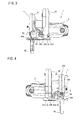
- FIG. 3 is a front view of the portable cutting device according to the embodiment;
- FIG. 4 is a rear view of the portable cutting device according to the embodiment;
- FIG. 5 (a) is a rear view of a saw cover of the portable cutting device according to the embodiment;
- FIG. 5(b) an enlarged cross-sectional side view of a rear portion of the saw cover in a cutting direction;
- FIG. 6 (a) is a plan view of a link of the portable cutting device according to the embodiment;
- FIG. 6(b) is a cross-sectional view taken along the line VI-VI;
- FIG. 7 is a side cross-sectional view depicting a periphery of a connecting part of the portable cutting device according to the embodiment;
- FIG. 8 is a perspective view depicting a bolt of the portable cutting device according to the embodiment;
- FIG. 9(a) is a front perspective view depicting a washer of the portable cutting device according to the embodiment;
- FIG. 9(b) is a rear perspective view of the washer;
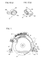
- FIG. 10(a) is a front perspective view depicting a pivot operation part of the portable cutting device according to the embodiment;
- FIG. 10(b) is a rear perspective view of the pivot operation part;
- FIG. 11 is a side view showing the portable cutting device according to the embodiment and observed from the opposite side to the housing in a state where an amount of protrusion of a circular saw blade is changed;
- FIG. 12 is a side cross-sectional view depicting a connecting part in the embodiment in a state where a saw cover body part and a guide are tightened;
- FIG. 13 is a plan view depicting the washer and the pivot operation part of the portable cutting device according to the embodiment;
- FIG. 14 is a plan view depicting the washer and the pivot operation part of the portable cutting device according to the embodiment in a state where the pivot operation part is pivotally moved;
- FIG. 15 is a perspective view of a washer according to a modification to the embodiment; and
- FIG. 16 is a perspective view of a pivot operation part according to a modification to the embodiment.
- A portable cutting device according to an embodiment of the present invention will be described with reference to FIGS. 1 to 16. A
circular saw 1 shown in FIG. 1 mainly includes ahousing 2, acircular saw blade 3, asaw cover 4 and abase 6. - The
housing 2 mainly includes amotor accommodation part 21 accommodating therein amotor 2A, and ahandle part 22 integral with themotor accommodation part 21. A drive system (not shown) driven by themotor 2A is provided in thesaw cover 4. Acircular saw blade 3 is rotationally driven by the drive system. Thehandle part 22 is provided with a switch (not shown) for controlling driving of themotor 2A, and astopper 22A (FIG. 1) for holding the switch in an ON state. - The
saw cover 4 is provided at a position opposite to themotor accommodation part 21 with respect to thehandle 22. As shown in FIG. 2, thesaw cover 4 includes a sawcover body part 41 connected to thehousing 2, and asafety cover 42 provided on the sawcover body part 41 for covering thecircular saw blade 3. - The saw
cover body part 41 is made from a metal and covers substantially a half of thecircular saw blade 3 as shown in FIG. 2. A connectingpart 41A is provided at one end of the sawcover body part 41 in a circumferential direction thereof The connectingpart 41A is adapted to be connected to apivot support part 62 described later. Arib 41B (FIG. 1) is provided at the sawcover body part 41 at a position coincident with thecircular saw blade 3. As shown in FIG. 5 (a) and FIG. 5 (b), The sawcover body part 41 has another end in the circumferential direction formed with arectangular groove part 41a as a substantially square concave part at a position in line with therib 41B. Further, a through-hole 41b is formed in a bottom part of therectangular groove part 41a. - A tightening
part 5 is disposed at therectangular groove part 41a and the through-hole 41b for tightening and releasing aguide 65A (described later) relative to the sawcover body part 41. Afirst stopper 41C protrudes from the sawcover body part 41 at a position near therectangular groove part 41a and in approximate alignment with therib 41B. Asecond stopper 41D protrudes from the sawcover body part 41 in substantially the same protruding direction as thefirst stopper 41C. Thesecond stopper 41D is positioned at an end portion of the sawcover body part 41 and near therectangular groove part 41a. - The
safety cover 42 is pivotally supported to the sawcover body part 41 and is movable along the sawcover body part 41 in the circumferential direction thereof. A spring (not shown) is interposed between the sawcover body part 41 and thesafety cover 42 for biasing thesafety cover 42 in a circumferential direction of the sawcover body part 41 from the other end side toward the one end side of the sawcover body part 41. Therefore, while cutting work is not carried out, thesafety cover 42 covers, in a direction from the another end side toward the one end side, a remaining part of thecircular saw blade 3 which is not covered by the sawcover body part 41. - Accordingly, the
circular saw blade 3 can be partly exposed to an atmosphere at an area between the one end of the sawcover body part 41 and a leading end of thesafety cover 42. This exposing area of the blade serves as a cutting area to cut a workpiece W, allowing thecircular saw 1 to move forward for cutting the wooden material in a direction from the other end to the one end of the sawcover body part 41. Hence, the direction from the other end to the one end of the sawcover body part 41 is defined as a cutting direction. The one end side of the sawcover body part 41 is defined as a leading end side in the cutting direction, as well as the other end side a rear side in the cutting direction. - As shown in FIG. 1, the
base 6 includes abase member 61, thepivot support part 62, afirst bevel plate 63, asecond bevel plate 64, and alink 65 serving as an adjustment guide. Thebase 6 pivotably and laterally tiltably supports thehousing 2,circular saw blade 3, and sawcover 4 through thesaw cover 4. Thebase member 61 is a main constituent of thebase 6 having a substantially rectangular plate like shape and made from a metal. A major side of thebase member 61 is oriented in the cutting direction. Anelongated slot 6a extending in the lengthwise direction is formed in thebase member 61. Theelongated slot 6a allows thecircular saw blade 3 and thesafety cover 42 to pass therethrough. - As shown in FIG. 1, the
second bevel plate 64 andpivot support part 62 are provided at the front side of theelongated slot 6a in the cutting direction in thebase member 61. As shown in FIG. 3, thesecond bevel plate 64 extends vertically from thebase member 61 in a direction substantially perpendicular to the cutting direction, and has a secondtilt axis part 64A extending in the cutting direction. Anarcuate slot 64a whose center of radius is coincident with the secondtilt axis part 64A is formed in thesecond bevel plate 64. - As shown in FIG. 1, the
pivot support part 62 is laterally tiltably movably supported to the secondtilt axis part 64A. Thepivot support part 62 has a pair of arm parts extending toward the rear side in the cutting direction. The arm parts are provided with apivot axis part 62A whose axis extends perpendicular to the cutting direction. Thispivot axis part 62A pivotally movably supports the connectingpart 41A positioned at front side of the sawcover body part 41 in the cutting direction. - The
pivot support part 62 is formed with a female thread (not shown). Ascrew 62B extends through thearcuate slot 64a of thesecond bevel plate 64 and is threadingly engaged with the female screw. Upon fastening thescrew 62B the tilt angle of thepivot support part 62 relative to thesecond bevel plate 64 can be fixed to an arbitrary angle. - As shown in FIGS. 1 and 2, the
first bevel plate 63 and link 65 are provided at a rear side of theelongated slot 6a in the cutting direction in thebase member 61. As shown in FIG. 4, thefirst bevel plate 63 is configured to have a shape symmetrical to thesecond bevel plate 64 with respect to theelongated slot 6a. A firsttilt axis part 63A is provided on an extension of the secondtilt axis part 64A. Anarcuate slot 63a whose center of radius is coincident with the firsttilt axis part 63A is formed in thefirst bevel plate 63. - As shown in FIGS. 6(a) and 6(b), the
link 65 is constituted by aguide 65A extending substantially arcuate fashion, and abase part 65B provided at a base end of theguide 65A. As shown in FIG. 7, thelink 65 is inserted inside the sawcover body part 41 along an inner peripheral wall thereof. - As shown in FIGS. 6 (a) and 6(b), the
guide 65A is formed with aslit 65a extending in a lengthwise direction thereof, and a through-hole 65b positioned at a base end side of theguide 65A. Abolt 51 described later extends through theslit 65a with sliding relation thereto. Thehole 65b allows the firsttilt axis part 63A to be inserted. Thebase part 65B is positioned in superposed relation to thefirst bevel part 63. An arc-type slit 65c is formed in thebase part 65B such that a distance between thehole 65b and the arc-type slit 65c is substantially equal to a distance between the firsttilt axis part 63A and thearcuate slot 63a of thefirst bevel part 63. - A
screw fastener 63B penetrates through the arc-type slit 65c and thearcuate slot 63a. A tilt angle of thelink 65 relative to thefirst bevel plate 63 can be fixed to an arbitrary angle by thescrew fastener 63B. Accordingly, thefirst bevel plate 63 andsecond bevel plate 64 enables thehousing 2 and sawcover 4 to be tilted in lateral direction of FIG. 3 via thelink 65 andpivot support part 62. - As shown in FIG. 1, a
pointer part 67 indicating a cutting position is provided at a frontmost end of thebase member 61 in the cutting direction. Thepointer part 67 is positioned in alignment with an intersection between a plane including thecircular saw blade 3 and thebase member 61. Thebase member 61 has acontact face 61A which contacts a surface of the workpiece at an opposite surface where thesecond bevel plate 64 and the like are provided. - The tightening
part 5 shown in FIGS. 1 and 7 includes thebolt 51, awasher 52, apivot operation part 53, and anut 54. A regulator part is constituted by the tighteningpart 5 and theguide 65A, and a protrusion change mechanism for thecircular saw blade 3 is constituted by the regulator part and thepivot support part 62. - As shown in FIG. 8, the
bolt 51 has ashaft part 51A, aflange part 51B, asquare part 51C and athread part 51D. Theflange part 51B is provided at a base end side of theshaft part 51. Thesquare part 51C is positioned between theshaft part 51A and theflange part 51B and has a substantially square cross-section in a direction perpendicular to axial direction of theshaft part 51A. The threadedpart 51D is provided at a tip end side of theshaft part 51A. - The
square part 51C has a side having a length substantially equal to a width of theslit 65a in thelink 65. Thebolt 51 is associated with the sawcover body part 41 and thelink 65 in such a manner that theshaft part 51A penetrates through theslit 65a and a through-hole 41b, and thesquare part 51C is inserted into and engaged with theslit 65a. Since thesquare part 51C is inserted in theslit 65a, the rotation of thebolt 51 about its axis is prevented. - As shown in FIGS. 9(a) and 9(b), the
washer 52 has one end face provided with arectangular protrusion part 52A having a substantially square cross-section. Thewasher 52 has another end face provided with a pair ofconvex parts 52B which face and contact thepivot operation part 53, a pair ofconcave parts 52d, and a plurality ofslope parts 52C each defined between each one of the pair ofconvex parts 52B and each one of the pair ofconcave parts 52d. A through-hole 52a penetrating from one end face to the other end face is formed at a substantial center position of thewasher 52. The plurality ofslope parts 52C each defined between each one of the pair ofconvex parts 52B and each one of the pair ofconcave parts 52d are arrayed at an even pitch in a circumferential direction around the through-hole 52a. - The
square protrusion part 52A has a side length substantially equal to a side length of therectangular groove part 41a. Therefore, as shown in FIG. 7, thewasher 52 is attached to the sawcover body part 41 such that therectangular protrusion part 52A is fitted with therectangular groove part 41a. In this manner, thewasher 52 can be held by the sawcover body part 41 while rotation of thewasher 52 about the axis of the through-hole 52a is prevented. Theshaft part 51A of thebolt 51 is inserted through the through-hole 52a. Further, thewasher 52 is configured as a member separate from the sawcover body part 41, theguide 65A, and the like. Therefore, thewasher 52 can be made from an impregnated material, typically a bearing material having high durability and lubricity. - As shown in FIG. 10, the
pivot operation part 53 includes abody part 53A and alever 53B. Thebody part 53A has a center portion formed with a through-hole 53a penetrating through a thickness thereof. Thebody part 53A has one end face provided with a pair ofprotrusion parts 53C around the throughhole 53a. Theprotrusion parts 53C are adapted to face and contact with the other end face of thewasher 52. The pair ofprotrusion parts 53C are arrayed around the through-hole 53a at an even pitch in a circumferential direction of the through-hole 53a. Aprotrusion 53D protrudes from the one end face of thebody part 53A at a position near one of theprotrusion part 53C and remote from the through-hole 53a. Protruding direction of theprotrusion 53D is equal to that of theprotrusion parts 53C. Thelever 53B extends from a peripheral part of thepivot operation part 53 in a direction substantially perpendicular to an axis of the through-hole 53a. - The
pivot operation part 53 is set on thewasher 52 so that the pair ofprotrusion parts 53C are brought into abutment with the pair ofconcave parts 52d of thewasher 52. Theshaft part 51A of thebolt 51 extends through the through-hole 53a. In this case, theprotrusion 53D is positioned between thefirst stopper 41C and thesecond stopper 41D (see FIG. 5(a)). Theprotrusion 53D is abuttable against thefirst stopper 41C and thesecond stopper 41D to prevent thepivot operation part 53 from its excessive rotation, to thus prevent theprotrusion parts 53C from climbing over theprotrusion parts 52B. - The threaded
part 51D of thebolt 51 penetrating the through-hole 53a is fastened with anut 54 while interposing aflat washer 54A between thenut 54 and thepivot operation part 53. Therefore, theguide 65A, sawcover body part 41,washer 52,pivot operation part 53, andflat washer 54A are interposed between theflange part 51B and thenut 54. - In operation, for changing an amount of protrusion of the
circular saw blade 3 from thecontact face 61A, thehousing 2 and thesaw cover 4 are pivoted about thepivot axis part 62A of thepivot support part 62 such that thepivot axis part 62A functions as a fulcrum. At this time, the sawcover body part 41 is slidingly moved relative to theguide 65A. Thus, thehousing 2 and thesaw cover 4 are moved up and down in FIG. 2 about thepivot axis part 62A relative to thebase 6. As a result, the amount of protrusion of thecircular saw blade 3 from thecontact face 61A changes (FIG. 11). - To fix the posture of the
housing 2 and sawcover 4 relative to thebase 6 for maintaining the intended protrusion amount, thepivot operation part 53 is pivoted as shown in FIG. 12. More specifically, thelever 53B is pivoted in a clockwise direction in FIG. 4 so that an extension direction of thelever 53B is substantially parallel to the direction of therib 41B. Since thelever 53B is set substantially parallel to therib 41B upon fixing, thelever 53B can be prevented from protruding out from thesaw cover 4 toward thehousing 2 and toward a side opposite to thehousing 2. Therefore, thelever 53B does not affect tilting operation when thesaw cover 4 is to be laterally tilted relative to thebase 6 about the first and secondtilt axis parts lever 53B does not affect cutting operation while thesaw cover 4 and the saw blade is laterally tilted relative to thebase 6. - Alternatively, the
lever 53B can be configured to be oriented toward the side of themotor 2A when theprotrusion part 53C is positioned closest to theconvex part 52B. In the latter case, accidental abutment of thelever 53B onto thebase 6 can be avoided when thesaw cover 4 is laterally tilted to a side opposite to themotor 2A. - Prior to pivoting motion of the
pivot operation part 53, thepivot operation part 53 and thewasher 52 are in contact with each other while the pair ofprotrusion parts 53C are faced to the pair ofconcave parts 52d as shown in FIG. 13. By pivoting thepivot operation part 53, theprotrusion parts 53C slide on theslope parts 52C to move close to theconvex parts 52B as shown in FIG. 14. Incidentally, since theprotrusion 53D of thepivot operation part 53 is located between thefirst stopper 41C and thesecond stopper 41D (FIG. 9(a)), pivoting motion of thepivot operation part 53 is restricted in such a manner that the pair ofprotrusion parts 53C do not climb over theconvex part 52B. - Since the plurality of
protrusion parts 53C and the plurality ofconvex parts 52B are arrayed at an even pitch, thepivot operation part 53 and thewasher 52 relatively move away from each other in axis direction of the bolt in parallel with each other as thepivot operation part 53 is pivoted. Therefore, as shown in FIG. 12, a distance in an axial direction of thebolt 51 from an end face of thepivot operation part 53 at the side of thenut 54 to an end face of thewasher 52 at the side of the sawcover body part 41 becomes longer than that the state prior to the pivotal motion of thepivot operation part 53 as shown in FIG. 7. - However, a distance from the end face of the
nut 54 to an end face of theflange part 51B is unchanged before and after pivoting thepivot operation part 53. Therefore, a distance from thewasher 52 to theflange part 51B is shortened as the distance from thepivot operation part 53 to thewasher 52 is increased. As a result, theguide 65A is urged toward the sawcover body part 41 by theflange part 51B, and the sawcover body part 41 and guide 65A are fixedly held between thewasher 52 andflange part 51B. Consequently, the position of thehousing 2 and thesaw cover 4 relative to thebase 6 is fixed, so that the amount of protrusion of thecircular saw blade 3 from thecontact face 61 is fixed. - The
pivot operation part 53 need not be rotated a large number of times, but thehousing 2 and thecircular saw blade 3 can be suitably fixed to thebase 6 at a predetermined pivot angle by the angular pivoting motion of thepivot operation part 53. When fixing the sawcover body part 41 and theguide 65A together, increased moving distance of thewasher 52 can result per angular movement of thepivot operation part 53. This is in high contrast to the axial moving distance of an ordinary screw in accordance with its screwing motion. Thus, in the above described embodiment, since thewasher 52 can be moved relatively greater stroke in the axial direction of theshaft part 51A, prompt fixing and prompt release of thesaw cover 4 relative to thebase 6 can be performed. - In the above configuration, since two or more
convex parts 52B are arrayed evenly in a circumferential direction, thepivot operation part 53 and thewasher 52 move relatively in their axial directions in parallel with each other. Accordingly, force acting on thewasher 52 is not deviated when thepivot operation part 53 is operated. Therefore, the tighteningpart 5 does not cause rattling but the sawcover body part 41 and guide 65A can be fixed suitably upon tightening. Consequently, unwanted change in cutting depth during tightening operation can be avoided, and prolonged service life of components can result. Since a position of thepivot operation part 53 in the axial direction of theshaft part 51A can be defined by thenut 54, fine adjustment can be carried out to maintain suitable tightening, even when theconvex parts 52B andprotrusion parts 53C are frictionally worn. - According to the above-described embodiment, the
pivot operation part 53 is provided with aprotrusion 53D to regulate the pivot angle of thepart 53. However, theprotrusion 53D can be dispensed with. In the latter case, theprotrusion parts 53C of thepivot operation part 53 slides on one of theslop parts 52C and can be positioned near the pair ofconvex parts 52B, regardless of the pivotal moving direction (clockwise or counterclockwise direction) of thepivot operation part 53. Accordingly, thepivot operation part 53 and thewasher 52 move away relatively from each other in parallel with each other. The sawcover body part 41 and guide 65A can thus be tightened suitably. - FIGS. 15 and 16 show modifications to a washer and a pivot operation part, respectively. In FIG. 15, a
washer 152 can be provided with a pair ofstep parts 152A. An upper stage of each of thestep part 152A is defined as aconvex part 152B, and a lower stage thereof is defined as aconcave part 152d. Each face connecting theconvex part 152B of onestep part 152A to theconcave part 152d of anotherstep part 152A is defined as aslop part 152C. Similarly, in apivot operation part 153 as shown in FIG. 16, a pair ofsimilar step parts step parts 153A is defined as aprotrusion part 153B. Further, thepivot operation part 153 and thewasher 152 are brought into contact with each other so that theprotrusion parts 153B and theconcave parts 152d face each other. According to this configuration, in case of pivoting in one circumferential direction of a bolt now shown, thestep parts 152A of thewasher 152 and thestep parts 153A of thepivot operation part 153 are abuttable with each other, thereby preventing pivoting. In case of pivoting in another circumferential direction, thestep parts protrusion parts 153B can slide on theslop parts 152C so that thepivot operation part 153 and thewasher 152 can be moved away relatively from each other in parallel with each other. - Also, in the above-described embodiment, the pivot operation part is provided with protrusion parts, whereas the washer is provided with concave and convex parts. However, the pivot operation part can be provided with concave and convex parts whereas the washer can be provided with protrusion parts.
- Further, in the above-described embodiment, the
shaft part 51A of thebolt 51 can be unrotatably supported to theguide 65. However, the shaft part can be rotatably supported to theguide 65. In the latter case, the pivot motion of the pivot operation part and rotation of the shaft part must be concurrently performed. That is, the pivot operation part and the shaft part can be integrally formed. - While the invention has been described in detail and with reference to specific embodiment thereof, it would be apparent to those skilled in the art that various changes and modifications may be made therein without departing from the spirit and scope of the invention.
Claims (11)
- A portable cutting device comprising:a housing;a motor disposed in the housing;a circular saw blade driven by the motor for cutting a workpiece;a saw cover provided to the housing and covering a generally half region of the circular saw blade;a base supporting the saw cover and in contact with the workpiece to be cut; anda mechanism for changing protrusion amount of the circular saw blade from the base; the mechanism comprising a pivot support portion that pivotably movably supports the saw cover with respect to the base, and a regulating portion that selectively fixes a pivot posture of the saw cover relative to the base, the regulating portion comprising:an adjustment guide extending from the base in a pivotally moving direction of the saw cover in a superposed relation to the saw cover; anda tightening unit disposed at a position superposed with the adjustment guide and the saw cover for providing a selective tightening between the saw cover and the adjustment guide the tightening unit comprising:a shaft part extending through the saw cover and the adjustment guide and extending out of the saw cover;a pivot operation part pivotally movable about an axis of the shaft part; andan urging part disposed over the shaft part and in contact with the pivot operation part, the urging part being movable in a direction of the axis of the shaft part upon pivot movement of the pivot operation part for increasing a tightening force between the saw cover and the adjustment guide.
- The portable cutting device as claimed in claim 1,
wherein one of the urging part and the pivot operation part is provided with a convex part protruding toward the remaining one of the urging part and the pivot operation part, and a slope part sloping down from the convex part, the convex part and the slope part being alternately arrayed in a circumferential direction of the shaft part; and
wherein remaining one of the urging part and the pivot operation part is provided with a protrusion part protruding toward the one of the urging part and the pivot operation part and in abutment with the one of the urging part and the pivot operation part, the protrusion part being slidable on the slope part. - The portable cutting device as claimed in claim 2,
wherein the convex part includes a plurality of convex parts arrayed around the shaft part at equal interval in the circumferential direction; and
wherein the protrusion part includes a plurality of protrusion parts corresponding to the plurality of convex parts and arrayed around the shaft part at equal interval in the circumferential direction. - The portable cutting device as claimed in claim 2,
wherein the pivot operation part comprises a body part disposed over the shaft part, and a lever part extending from the body part in a direction perpendicular to the shaft part, the lever part being configured to be oriented in parallel to a plane containing the circular saw blade when the protrusion part is positioned closest to the convex part. - The portable cutting device as claimed in claim 2,
wherein the pivot operation part comprises a body part disposed over the shaft part, and a lever part extending from the body part in a direction perpendicular to the shaft part, and,
wherein the motor is disposed at one circular plane side of the circular saw blade, the lever part being configured to be oriented toward the motor when the protrusion part is positioned closest to the convex part. - The portable cutting device as claimed in claim 2,
wherein the convex part includes at least a first convex part and a second convex part arrayed around the shaft part in a circumferential direction thereof, and
wherein the slope part includes at least a first slope part sloping from the first convex part, and a second slope part sloping from the second convex part and connected to the first slope part, the projection part being slidable on either one of the first slope part and the second slope part. - The portable cutting device as claimed in claim 6,
wherein the pivot operation part comprises a body part disposed over the shaft part, and a lever part extending from the body part in a direction perpendicular to the shaft part, the body part having an abutment protrusion, and the portable cutting device further comprising:a first stopper and a second stopper those protruding from the saw cover at positions to allow the abutment protrusion to be brought into abutment thereto for avoiding over-rotation of the body part to prevent the projection part from climbing over the convex part. - The portable cutting device as claimed in claim 2,
wherein the convex part includes at least a first convex part and a second convex part arrayed around the shaft part in a circumferential direction thereof, and
wherein the slope part includes at least a first slope part sloping from a top of the first convex part to a bottom of the second convex part, and a second slope part sloping from a top of the second convex part to a bottom of the first convex part, the projection part being slidable on one of the first slope part and the second slope part. - The portable cutting device as claimed in claim 1,
wherein the urging part is a separate component independent of the saw cover and the adjustment guide. - The portable cutting device as claimed in claim 1,
wherein the shaft portion has a tip end portion formed with a thread portion; and
wherein the tightening unit further comprises a nut threadingly engaged with the thread portion and positioned opposite to the saw cover with respect to the pivot operation part for adjusting a position of the pivot operation part in an axial direction of the shaft part. - The portable cutting device as claimed in claim 1, further comprising a tilt mechanism for laterally tilting the saw cover relative to the base and selectively fixing a tilting posture of the saw cover.
Applications Claiming Priority (1)
| Application Number | Priority Date | Filing Date | Title |
|---|---|---|---|
| JP2006045945A JP4780524B2 (en) | 2006-02-22 | 2006-02-22 | Portable cutting machine |
Publications (2)
| Publication Number | Publication Date |
|---|---|
| EP1825974A1 true EP1825974A1 (en) | 2007-08-29 |
| EP1825974B1 EP1825974B1 (en) | 2014-05-07 |
Family
ID=37865700
Family Applications (1)
| Application Number | Title | Priority Date | Filing Date |
|---|---|---|---|
| EP07001764.5A Not-in-force EP1825974B1 (en) | 2006-02-22 | 2007-01-26 | Portable cutting device with a cutting depth adjustment |
Country Status (4)
| Country | Link |
|---|---|
| US (1) | US8104183B2 (en) |
| EP (1) | EP1825974B1 (en) |
| JP (1) | JP4780524B2 (en) |
| CN (1) | CN101024289B (en) |
Cited By (1)
| Publication number | Priority date | Publication date | Assignee | Title |
|---|---|---|---|---|
| CN102216042A (en) * | 2008-12-17 | 2011-10-12 | 博世电动工具(中国)有限公司 | Circular saw with splash guard |
Families Citing this family (18)
| Publication number | Priority date | Publication date | Assignee | Title |
|---|---|---|---|---|
| JP4998849B2 (en) * | 2007-09-07 | 2012-08-15 | 日立工機株式会社 | Portable cutting machine |
| JP4941755B2 (en) * | 2007-09-07 | 2012-05-30 | 日立工機株式会社 | Portable cutting machine |
| JP5120781B2 (en) * | 2008-07-31 | 2013-01-16 | 日立工機株式会社 | Portable cutting machine |
| US8919235B2 (en) | 2009-03-17 | 2014-12-30 | Hitachi Koki Co., Ltd. | Cutting apparatus |
| GB201102368D0 (en) * | 2011-02-10 | 2011-03-30 | 7Rdd Ltd | Powered circular saw and method of use thereof |
| CN102744458B (en) * | 2011-04-22 | 2016-03-02 | 博世电动工具(中国)有限公司 | Portable cutting tool |
| US9694508B2 (en) * | 2011-09-30 | 2017-07-04 | Robert Bosch Tool Corporation | Base lever with release stop and lock stop |
| DE102011086337A1 (en) | 2011-11-15 | 2013-05-16 | Robert Bosch Gmbh | Cutting depth limiter |
| CN106424920A (en) * | 2012-07-13 | 2017-02-22 | 苏州宝时得电动工具有限公司 | Portable cutting machine |
| DE102013212562B4 (en) * | 2013-06-28 | 2025-02-13 | Robert Bosch Gmbh | Cutting length display device for a hand tool |
| CN103752943B (en) * | 2013-09-25 | 2016-01-20 | 江苏苏美达五金工具有限公司 | A kind of portable circular saw |
| WO2016146146A1 (en) * | 2015-03-13 | 2016-09-22 | Husqvarna Ab | Arrangement for automatic adjustment of a spacing between cutting blades |
| CN105269618A (en) * | 2015-10-28 | 2016-01-27 | 林蓉瑶 | First-aid cutting machine quantification device |
| JP6847651B2 (en) * | 2016-09-01 | 2021-03-24 | 株式会社マキタ | Portable cutting machine |
| US10875109B1 (en) | 2018-04-30 | 2020-12-29 | Kreg Enterprises, Inc. | Adaptive cutting system |
| JP7290557B2 (en) * | 2019-11-29 | 2023-06-13 | 株式会社マキタ | lever device |
| EP4171856B1 (en) * | 2020-06-25 | 2025-07-30 | Festool GmbH | Plunge saw with cut indicators and method of operating a plunge saw |
| CN112473902B (en) * | 2020-11-16 | 2022-02-08 | 江山华隆能源开发有限公司 | Pelletizing device of caking is prevented to living beings granule |
Citations (3)
| Publication number | Priority date | Publication date | Assignee | Title |
|---|---|---|---|---|
| US4221051A (en) * | 1979-05-30 | 1980-09-09 | The Singer Company | Circular saw with improved base plate adjustment |
| US5381602A (en) * | 1992-11-19 | 1995-01-17 | Robert Bosch Gmbh | Electric motor operated hand circular saw |
| JP2004330657A (en) * | 2003-05-08 | 2004-11-25 | Hitachi Koki Co Ltd | Portable electric cutting machine |
Family Cites Families (21)
| Publication number | Priority date | Publication date | Assignee | Title |
|---|---|---|---|---|
| US949179A (en) * | 1907-04-08 | 1910-02-15 | Royal H Gilbert | Driving-axle. |
| US3262472A (en) * | 1964-05-08 | 1966-07-26 | Black & Decker Mfg Co | Depth and bevel adjustment means for portable power-driven saw |
| US3417802A (en) * | 1967-11-16 | 1968-12-24 | Carl O. Oldenkott | Captive lock washer assembly |
| JPS59167202A (en) * | 1983-03-15 | 1984-09-20 | 松下電工株式会社 | Circular saw |
| US4957235A (en) * | 1989-03-22 | 1990-09-18 | Beno Steven J | Paper trimmer |
| US4982501A (en) * | 1990-03-05 | 1991-01-08 | Black & Decker Inc. | Depth of cut adjustment for a portable circular saw |
| US5011351A (en) * | 1990-03-19 | 1991-04-30 | Terry Sydney L | Wedge lock die washer |
| US5090855A (en) * | 1990-03-19 | 1992-02-25 | Terry Sydney L | Locking fastener assembly |
| US5394968A (en) * | 1993-05-19 | 1995-03-07 | Yu-Shu; Lin | Clutch applied between transmission shaft and wheel of an electric cart |
| JP2978674B2 (en) * | 1993-06-18 | 1999-11-15 | リョービ株式会社 | Position adjustment device for circular saw blade of cutting machine |
| US5626449A (en) * | 1995-09-15 | 1997-05-06 | Hong Kong Disc Lock Company Limited | Wedge-locking fastener assembly with a cammed flange |
| US5870938A (en) * | 1995-12-12 | 1999-02-16 | Black & Decker Inc. | Bevel locking system for a sliding compound miter saw |
| US5733061A (en) * | 1996-03-15 | 1998-03-31 | Zevex, Inc. | Clamp |
| US5758425A (en) * | 1997-05-20 | 1998-06-02 | S-B Power Tool Company | Depth-of-cut mechanism for circular saw |
| US6347915B1 (en) * | 1998-08-17 | 2002-02-19 | Alfiero Balzano | Lock washer for threaded fasteners |
| US7128511B2 (en) * | 1998-10-30 | 2006-10-31 | John Hewgill | Fastener |
| AUPQ611800A0 (en) * | 2000-03-09 | 2000-03-30 | Smolarek, Hanna Maria | Washer and threaded fastener assembly incorporating same |
| JP4283464B2 (en) * | 2001-08-02 | 2009-06-24 | 株式会社マキタ | Marunoco |
| WO2004033139A2 (en) * | 2002-10-09 | 2004-04-22 | Terry Sydney L | Wedge cam lock washer for threaded fasteners |
| US7296356B2 (en) * | 2004-04-14 | 2007-11-20 | Eastway Fair Company Limited | Toolless adjustable base for a portable saw |
| JP2006035365A (en) * | 2004-07-26 | 2006-02-09 | Hitachi Koki Co Ltd | Portable cutting tool |
-
2006
- 2006-02-22 JP JP2006045945A patent/JP4780524B2/en not_active Expired - Fee Related
-
2007
- 2007-01-26 EP EP07001764.5A patent/EP1825974B1/en not_active Not-in-force
- 2007-02-08 CN CN2007100054020A patent/CN101024289B/en not_active Expired - Fee Related
- 2007-02-22 US US11/677,602 patent/US8104183B2/en not_active Expired - Fee Related
Patent Citations (3)
| Publication number | Priority date | Publication date | Assignee | Title |
|---|---|---|---|---|
| US4221051A (en) * | 1979-05-30 | 1980-09-09 | The Singer Company | Circular saw with improved base plate adjustment |
| US5381602A (en) * | 1992-11-19 | 1995-01-17 | Robert Bosch Gmbh | Electric motor operated hand circular saw |
| JP2004330657A (en) * | 2003-05-08 | 2004-11-25 | Hitachi Koki Co Ltd | Portable electric cutting machine |
Cited By (2)
| Publication number | Priority date | Publication date | Assignee | Title |
|---|---|---|---|---|
| CN102216042A (en) * | 2008-12-17 | 2011-10-12 | 博世电动工具(中国)有限公司 | Circular saw with splash guard |
| CN102216042B (en) * | 2008-12-17 | 2014-08-20 | 博世电动工具(中国)有限公司 | Circular saw with splash guard |
Also Published As
| Publication number | Publication date |
|---|---|
| JP2007223133A (en) | 2007-09-06 |
| JP4780524B2 (en) | 2011-09-28 |
| EP1825974B1 (en) | 2014-05-07 |
| CN101024289A (en) | 2007-08-29 |
| CN101024289B (en) | 2011-06-15 |
| US20070193040A1 (en) | 2007-08-23 |
| US8104183B2 (en) | 2012-01-31 |
Similar Documents
| Publication | Publication Date | Title |
|---|---|---|
| EP1825974B1 (en) | Portable cutting device with a cutting depth adjustment | |
| JP4954504B2 (en) | Portable circular saw | |
| JP3888165B2 (en) | Portable cutting machine | |
| EP1577066B1 (en) | Blade and motor carrier with height/angle adjustment mechanism | |
| US6513412B2 (en) | Adjustment mechanism | |
| US5046390A (en) | Miter saw | |
| US7726225B2 (en) | Miter saw having holder fixing mechanism | |
| US5433008A (en) | Circular saw with variable adjustment stops | |
| EP2149438B1 (en) | Portable cutting tool | |
| EP1579938B1 (en) | Miter saw having circular saw blade section pivotally movable upward and downward and tiltable leftward and rightward | |
| US7281332B2 (en) | Portable cutting tool | |
| US6553675B2 (en) | Quick release footplate assembly for a jigsaw | |
| US5722173A (en) | Saw blade adjusting mechanism | |
| US20060156888A1 (en) | Miter saw | |
| US7523691B2 (en) | Miter saw having digital display capable of displaying specific angle | |
| JP2007223133A5 (en) | ||
| US20050198834A1 (en) | Shoe clamping mechanism for power tool and power tool incorporating such mechanism | |
| CN100462172C (en) | Miter saw with angle adjustment mechanism | |
| JP2000052259A (en) | Vise equipment fence | |
| JP5398799B2 (en) | Portable circular saw | |
| JP2006069048A (en) | Tabletop cutting machine | |
| JP4446285B2 (en) | Portable cutting machine | |
| JP4870973B2 (en) | Electric tool | |
| CN2690103Y (en) | Multi-direction adjustment laser indicating device for cutting machine | |
| JP5105210B2 (en) | Tabletop cutting machine |
Legal Events
| Date | Code | Title | Description |
|---|---|---|---|
| PUAI | Public reference made under article 153(3) epc to a published international application that has entered the european phase |
Free format text: ORIGINAL CODE: 0009012 |
|
| AK | Designated contracting states |
Kind code of ref document: A1 Designated state(s): AT BE BG CH CY CZ DE DK EE ES FI FR GB GR HU IE IS IT LI LT LU LV MC NL PL PT RO SE SI SK TR |
|
| AX | Request for extension of the european patent |
Extension state: AL BA HR MK YU |
|
| 17P | Request for examination filed |
Effective date: 20080227 |
|
| AKX | Designation fees paid |
Designated state(s): AT BE BG CH CY CZ DE DK EE ES FI FR GB GR HU IE IS IT LI LT LU LV MC NL PL PT RO SE SI SK TR |
|
| 17Q | First examination report despatched |
Effective date: 20080415 |
|
| GRAP | Despatch of communication of intention to grant a patent |
Free format text: ORIGINAL CODE: EPIDOSNIGR1 |
|
| INTG | Intention to grant announced |
Effective date: 20131209 |
|
| GRAS | Grant fee paid |
Free format text: ORIGINAL CODE: EPIDOSNIGR3 |
|
| GRAA | (expected) grant |
Free format text: ORIGINAL CODE: 0009210 |
|
| AK | Designated contracting states |
Kind code of ref document: B1 Designated state(s): AT BE BG CH CY CZ DE DK EE ES FI FR GB GR HU IE IS IT LI LT LU LV MC NL PL PT RO SE SI SK TR |
|
| REG | Reference to a national code |
Ref country code: GB Ref legal event code: FG4D |
|
| REG | Reference to a national code |
Ref country code: DE Ref legal event code: R081 Ref document number: 602007036428 Country of ref document: DE Owner name: KOKI HOLDINGS CO., LTD., JP Free format text: FORMER OWNER: HITACHI KOKI CO., LTD., TOKIO/TOKYO, JP |
|
| REG | Reference to a national code |
Ref country code: AT Ref legal event code: REF Ref document number: 666243 Country of ref document: AT Kind code of ref document: T Effective date: 20140515 |
|
| REG | Reference to a national code |
Ref country code: IE Ref legal event code: FG4D |
|
| REG | Reference to a national code |
Ref country code: DE Ref legal event code: R096 Ref document number: 602007036428 Country of ref document: DE Effective date: 20140612 |
|
| REG | Reference to a national code |
Ref country code: AT Ref legal event code: MK05 Ref document number: 666243 Country of ref document: AT Kind code of ref document: T Effective date: 20140507 |
|
| REG | Reference to a national code |
Ref country code: NL Ref legal event code: VDEP Effective date: 20140507 |
|
| REG | Reference to a national code |
Ref country code: LT Ref legal event code: MG4D |
|
| PG25 | Lapsed in a contracting state [announced via postgrant information from national office to epo] |
Ref country code: GR Free format text: LAPSE BECAUSE OF FAILURE TO SUBMIT A TRANSLATION OF THE DESCRIPTION OR TO PAY THE FEE WITHIN THE PRESCRIBED TIME-LIMIT Effective date: 20140808 Ref country code: LT Free format text: LAPSE BECAUSE OF FAILURE TO SUBMIT A TRANSLATION OF THE DESCRIPTION OR TO PAY THE FEE WITHIN THE PRESCRIBED TIME-LIMIT Effective date: 20140507 Ref country code: FI Free format text: LAPSE BECAUSE OF FAILURE TO SUBMIT A TRANSLATION OF THE DESCRIPTION OR TO PAY THE FEE WITHIN THE PRESCRIBED TIME-LIMIT Effective date: 20140507 Ref country code: IS Free format text: LAPSE BECAUSE OF FAILURE TO SUBMIT A TRANSLATION OF THE DESCRIPTION OR TO PAY THE FEE WITHIN THE PRESCRIBED TIME-LIMIT Effective date: 20140907 Ref country code: CY Free format text: LAPSE BECAUSE OF FAILURE TO SUBMIT A TRANSLATION OF THE DESCRIPTION OR TO PAY THE FEE WITHIN THE PRESCRIBED TIME-LIMIT Effective date: 20140507 |
|
| PG25 | Lapsed in a contracting state [announced via postgrant information from national office to epo] |
Ref country code: AT Free format text: LAPSE BECAUSE OF FAILURE TO SUBMIT A TRANSLATION OF THE DESCRIPTION OR TO PAY THE FEE WITHIN THE PRESCRIBED TIME-LIMIT Effective date: 20140507 Ref country code: PL Free format text: LAPSE BECAUSE OF FAILURE TO SUBMIT A TRANSLATION OF THE DESCRIPTION OR TO PAY THE FEE WITHIN THE PRESCRIBED TIME-LIMIT Effective date: 20140507 Ref country code: SE Free format text: LAPSE BECAUSE OF FAILURE TO SUBMIT A TRANSLATION OF THE DESCRIPTION OR TO PAY THE FEE WITHIN THE PRESCRIBED TIME-LIMIT Effective date: 20140507 Ref country code: LV Free format text: LAPSE BECAUSE OF FAILURE TO SUBMIT A TRANSLATION OF THE DESCRIPTION OR TO PAY THE FEE WITHIN THE PRESCRIBED TIME-LIMIT Effective date: 20140507 Ref country code: ES Free format text: LAPSE BECAUSE OF FAILURE TO SUBMIT A TRANSLATION OF THE DESCRIPTION OR TO PAY THE FEE WITHIN THE PRESCRIBED TIME-LIMIT Effective date: 20140507 |
|
| PG25 | Lapsed in a contracting state [announced via postgrant information from national office to epo] |
Ref country code: PT Free format text: LAPSE BECAUSE OF FAILURE TO SUBMIT A TRANSLATION OF THE DESCRIPTION OR TO PAY THE FEE WITHIN THE PRESCRIBED TIME-LIMIT Effective date: 20140908 |
|
| PG25 | Lapsed in a contracting state [announced via postgrant information from national office to epo] |
Ref country code: RO Free format text: LAPSE BECAUSE OF FAILURE TO SUBMIT A TRANSLATION OF THE DESCRIPTION OR TO PAY THE FEE WITHIN THE PRESCRIBED TIME-LIMIT Effective date: 20140507 Ref country code: DK Free format text: LAPSE BECAUSE OF FAILURE TO SUBMIT A TRANSLATION OF THE DESCRIPTION OR TO PAY THE FEE WITHIN THE PRESCRIBED TIME-LIMIT Effective date: 20140507 Ref country code: CZ Free format text: LAPSE BECAUSE OF FAILURE TO SUBMIT A TRANSLATION OF THE DESCRIPTION OR TO PAY THE FEE WITHIN THE PRESCRIBED TIME-LIMIT Effective date: 20140507 Ref country code: EE Free format text: LAPSE BECAUSE OF FAILURE TO SUBMIT A TRANSLATION OF THE DESCRIPTION OR TO PAY THE FEE WITHIN THE PRESCRIBED TIME-LIMIT Effective date: 20140507 Ref country code: SK Free format text: LAPSE BECAUSE OF FAILURE TO SUBMIT A TRANSLATION OF THE DESCRIPTION OR TO PAY THE FEE WITHIN THE PRESCRIBED TIME-LIMIT Effective date: 20140507 Ref country code: BE Free format text: LAPSE BECAUSE OF FAILURE TO SUBMIT A TRANSLATION OF THE DESCRIPTION OR TO PAY THE FEE WITHIN THE PRESCRIBED TIME-LIMIT Effective date: 20140507 |
|
| REG | Reference to a national code |
Ref country code: DE Ref legal event code: R097 Ref document number: 602007036428 Country of ref document: DE |
|
| PG25 | Lapsed in a contracting state [announced via postgrant information from national office to epo] |
Ref country code: NL Free format text: LAPSE BECAUSE OF FAILURE TO SUBMIT A TRANSLATION OF THE DESCRIPTION OR TO PAY THE FEE WITHIN THE PRESCRIBED TIME-LIMIT Effective date: 20140507 |
|
| PLBE | No opposition filed within time limit |
Free format text: ORIGINAL CODE: 0009261 |
|
| STAA | Information on the status of an ep patent application or granted ep patent |
Free format text: STATUS: NO OPPOSITION FILED WITHIN TIME LIMIT |
|
| 26N | No opposition filed |
Effective date: 20150210 |
|
| PG25 | Lapsed in a contracting state [announced via postgrant information from national office to epo] |
Ref country code: IT Free format text: LAPSE BECAUSE OF FAILURE TO SUBMIT A TRANSLATION OF THE DESCRIPTION OR TO PAY THE FEE WITHIN THE PRESCRIBED TIME-LIMIT Effective date: 20140507 |
|
| REG | Reference to a national code |
Ref country code: DE Ref legal event code: R097 Ref document number: 602007036428 Country of ref document: DE Effective date: 20150210 |
|
| PG25 | Lapsed in a contracting state [announced via postgrant information from national office to epo] |
Ref country code: SI Free format text: LAPSE BECAUSE OF FAILURE TO SUBMIT A TRANSLATION OF THE DESCRIPTION OR TO PAY THE FEE WITHIN THE PRESCRIBED TIME-LIMIT Effective date: 20140507 |
|
| REG | Reference to a national code |
Ref country code: CH Ref legal event code: PL |
|
| PG25 | Lapsed in a contracting state [announced via postgrant information from national office to epo] |
Ref country code: LU Free format text: LAPSE BECAUSE OF FAILURE TO SUBMIT A TRANSLATION OF THE DESCRIPTION OR TO PAY THE FEE WITHIN THE PRESCRIBED TIME-LIMIT Effective date: 20150126 |
|
| PG25 | Lapsed in a contracting state [announced via postgrant information from national office to epo] |
Ref country code: MC Free format text: LAPSE BECAUSE OF FAILURE TO SUBMIT A TRANSLATION OF THE DESCRIPTION OR TO PAY THE FEE WITHIN THE PRESCRIBED TIME-LIMIT Effective date: 20140507 |
|
| PG25 | Lapsed in a contracting state [announced via postgrant information from national office to epo] |
Ref country code: LI Free format text: LAPSE BECAUSE OF NON-PAYMENT OF DUE FEES Effective date: 20150131 Ref country code: CH Free format text: LAPSE BECAUSE OF NON-PAYMENT OF DUE FEES Effective date: 20150131 |
|
| REG | Reference to a national code |
Ref country code: IE Ref legal event code: MM4A |
|
| REG | Reference to a national code |
Ref country code: FR Ref legal event code: PLFP Year of fee payment: 10 |
|
| PG25 | Lapsed in a contracting state [announced via postgrant information from national office to epo] |
Ref country code: IE Free format text: LAPSE BECAUSE OF NON-PAYMENT OF DUE FEES Effective date: 20150126 |
|
| REG | Reference to a national code |
Ref country code: FR Ref legal event code: PLFP Year of fee payment: 11 |
|
| PG25 | Lapsed in a contracting state [announced via postgrant information from national office to epo] |
Ref country code: HU Free format text: LAPSE BECAUSE OF FAILURE TO SUBMIT A TRANSLATION OF THE DESCRIPTION OR TO PAY THE FEE WITHIN THE PRESCRIBED TIME-LIMIT; INVALID AB INITIO Effective date: 20070126 Ref country code: BG Free format text: LAPSE BECAUSE OF FAILURE TO SUBMIT A TRANSLATION OF THE DESCRIPTION OR TO PAY THE FEE WITHIN THE PRESCRIBED TIME-LIMIT Effective date: 20140507 |
|
| PG25 | Lapsed in a contracting state [announced via postgrant information from national office to epo] |
Ref country code: TR Free format text: LAPSE BECAUSE OF FAILURE TO SUBMIT A TRANSLATION OF THE DESCRIPTION OR TO PAY THE FEE WITHIN THE PRESCRIBED TIME-LIMIT Effective date: 20140507 |
|
| REG | Reference to a national code |
Ref country code: FR Ref legal event code: PLFP Year of fee payment: 12 |
|
| REG | Reference to a national code |
Ref country code: DE Ref legal event code: R082 Ref document number: 602007036428 Country of ref document: DE Representative=s name: STREHL SCHUEBEL-HOPF & PARTNER MBB PATENTANWAE, DE Ref country code: DE Ref legal event code: R081 Ref document number: 602007036428 Country of ref document: DE Owner name: KOKI HOLDINGS CO., LTD., JP Free format text: FORMER OWNER: HITACHI KOKI CO., LTD., TOKYO, JP |
|
| REG | Reference to a national code |
Ref country code: DE Ref legal event code: R084 Ref document number: 602007036428 Country of ref document: DE |
|
| REG | Reference to a national code |
Ref country code: GB Ref legal event code: 746 Effective date: 20181030 |
|
| PGFP | Annual fee paid to national office [announced via postgrant information from national office to epo] |
Ref country code: GB Payment date: 20220119 Year of fee payment: 16 Ref country code: DE Payment date: 20220119 Year of fee payment: 16 |
|
| PGFP | Annual fee paid to national office [announced via postgrant information from national office to epo] |
Ref country code: FR Payment date: 20220119 Year of fee payment: 16 |
|
| REG | Reference to a national code |
Ref country code: DE Ref legal event code: R119 Ref document number: 602007036428 Country of ref document: DE |
|
| GBPC | Gb: european patent ceased through non-payment of renewal fee |
Effective date: 20230126 |
|
| PG25 | Lapsed in a contracting state [announced via postgrant information from national office to epo] |
Ref country code: GB Free format text: LAPSE BECAUSE OF NON-PAYMENT OF DUE FEES Effective date: 20230126 Ref country code: DE Free format text: LAPSE BECAUSE OF NON-PAYMENT OF DUE FEES Effective date: 20230801 |
|
| PG25 | Lapsed in a contracting state [announced via postgrant information from national office to epo] |
Ref country code: FR Free format text: LAPSE BECAUSE OF NON-PAYMENT OF DUE FEES Effective date: 20230131 |