EP1825947A1 - Pipe seam detection device of three-dimensional laser beam machine - Google Patents
Pipe seam detection device of three-dimensional laser beam machine Download PDFInfo
- Publication number
- EP1825947A1 EP1825947A1 EP07405030A EP07405030A EP1825947A1 EP 1825947 A1 EP1825947 A1 EP 1825947A1 EP 07405030 A EP07405030 A EP 07405030A EP 07405030 A EP07405030 A EP 07405030A EP 1825947 A1 EP1825947 A1 EP 1825947A1
- Authority
- EP
- European Patent Office
- Prior art keywords
- pipe
- seam
- laser beam
- dimensional laser
- sensor head
- Prior art date
- Legal status (The legal status is an assumption and is not a legal conclusion. Google has not performed a legal analysis and makes no representation as to the accuracy of the status listed.)
- Granted
Links
Images



Classifications
-
- B—PERFORMING OPERATIONS; TRANSPORTING
- B23—MACHINE TOOLS; METAL-WORKING NOT OTHERWISE PROVIDED FOR
- B23K—SOLDERING OR UNSOLDERING; WELDING; CLADDING OR PLATING BY SOLDERING OR WELDING; CUTTING BY APPLYING HEAT LOCALLY, e.g. FLAME CUTTING; WORKING BY LASER BEAM
- B23K26/00—Working by laser beam, e.g. welding, cutting or boring
- B23K26/08—Devices involving relative movement between laser beam and workpiece
- B23K26/0823—Devices involving rotation of the workpiece
Definitions
- the present invention relates to a device for detecting a weld seam on a pipe member which is equipped in a laser beam machine for processing pipe members and the like.
- Laser beam machines for processing pipe members perform laser processing to pipe members via a laser processing head while rotating a chuck holding the pipe member.
- Japanese Patent Application Laid-Open Publication No. 2001-150175 discloses a laser beam machine capable of processing pipes.
- the pipe material being subjected to processing can be a cylindrical pipe P 1 or a square pipe P 2 as illustrated in FIGS. 9A and 9B, and depending on the pipe material, the pipe can be a welded steel pipe in which a steel material is formed into a cylindrical or square pipe shape and the butted portion is bonded via welding.
- weld beads S 1 and S 2 which are called seams are formed along the axis line of the pipes.
- the seams deteriorate the appearance of the pipes, so it is preferable not to form the seams on the outer sides of the pipes if possible.
- the object of the present invention is to provide a laser beam machine having a detection device for detecting the position of the seam on a welded pipe.
- the three-dimensional laser beam machine has a sensor head coming into contact with a seam on an inner wall surface of the pipe to detect the position of the seam on the welded pipe.
- the pipe seam detection device comprises a sensor head and a means for moving the sensor head up and down, and the sensor head comprises a sensor lever coming into contact with the seam and a limit switch for detecting the movement of the sensor lever. Furthermore, the sensor head comprises an air nozzle for providing air blow to the portion to be detected.
- the sensor head is arranged close to a sensor lever, and the sensor head further comprises a lever that moves along the inner wall surface of the pipe in contact therewith.
- FIG. 1 is an explanatory view illustrating the outline of a three-dimensional laser beam machine to which the present invention is applied.
- the three-dimensional laser beam machine illustrated as a whole by reference number 1 comprises a base 10 and a processing unit 20 arranged at the center of the base 10.
- the processing unit 20 has a laser processing main body 30 arranged so as to be able to move in the axial direction.
- the laser processing main body 30 has a laser head 32 pivotally attached thereto.
- a work automatic loading device (loader) 40 and a product automatic unloading device (unloader) 50 are arranged on the front and rear of the processing unit 20.
- the three-dimensional laser beam machine 1 is equipped with four chucks 61, 62, 63 and 64 that move on the base 10.
- Each chuck is capable of holding works of various shapes such as pipe members and channel members, moving the work in the axial direction, controlling the rotation thereof and subjecting the work to three-dimensional laser processing.
- the three-dimensional laser beam machine 1 is equipped with a laser oscillator 70, a control panel 80, an NC device 90, an operating panel 92 and so on.
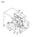
- FIG. 2 illustrates the details of the area near the processing unit 20, wherein the laser processing main body 30 is supported so as to be able to move in the axial direction on the processing unit 20.
- the laser processing main body 30 pivotally supports the laser head 32.
- FIG. 3 illustrates the weld seam detection device 100 according to the present invention equipped to the laser processing main body 30.
- the weld seam detection device 100 is equipped with a sensor head 110 and a driving device 300 for moving the sensor head 110 up and down.
- FIG. 4 is an explanatory view showing the basic principle of the sensor head 110.
- the sensor head 110 has a master lever 120 that comes into contact with an inner wall surface 410 of a cylindrical pipe 400 which is the object of detection (work).
- the master lever 120 is supported on a fixed member 170 via a floating mechanism including a spring 160 or the like.
- the cylindrical pipe 400 is rotated by the chuck 62, and the sensor head 110 moves in the direction perpendicular to the paper plane, but during this operation, a contact unit 122 disposed at the leading end of the master lever 120 is constantly in contact with the inner wall surface 410 of the cylindrical pipe 400.
- a sensor lever 140 is pivotally attached via a pin 130 on the master lever 120.
- the sensor lever 140 pivots around the pin 130 when a leading end 142 thereof comes into contact with a seam protruding from the inner wall surface 410 of the cylindrical pipe 400.
- a micro switch 150 detects the movement of a rear end 144 of the sensor lever 140, and sends a signal to the NC device 90.
- the NC device 90 recognizes that the current position of the sensor head 110 corresponds to the seam position on the cylindrical pipe 400, and executes the subsequent laser processing.
- FIG. 5 is a front view of the sensor head 110
- FIG. 6 is a right side view of FIG. 5.
- the master lever 120 and the like are supported in a cantilever via a pin 230 on the housing 200, and suspended via a spring 220 on the housing 200.
- the sensor lever 140 is disposed on the inner side of the master lever 120, and the movement thereof is detected via the micro switch 150.
- An air nozzle 210 is formed to have an opening disposed toward the leading end of the sensor lever 140, which provides an air blow A 1 to the inner side of the work to clean the same.
- FIG. 7 shows the process for detecting a seam 420 existing in the inner wall surface 410 of the cylindrical pipe 400.
- the sensor lever 140 is stopped at the orient position of the chuck while the cylindrical pipe 400 is rotated in the direction of arrow R 1 via the chuck, so as to recognize the angular position of the chuck when the sensor lever 140 contacts the seam 420.
- FIGS. 8A and 8B show the process for detecting a seam 470 existing in the inner wall surface of a square pipe 450.
- a seam 470 exists at the center portion of one of the four inner wall surfaces.
- the sensor lever 140 is moved in the direction of arrow F 1 together with the sensor head.
- the sensor lever 140 is moved out of the way, and the square pipe 450 is rotated for 90 degrees in the direction of arrow R 1 and stopped.
- the sensor lever 140 is moved in the direction of arrow F 1 to detect the existence of the seam 470.
- the NC device recognizes that the seam 470 exists on the inner wall surface 460b of the square pipe 450.
- the three-dimensional laser beam machine is capable of automatically detecting the seam position on the welded pipe, so as to enable the welded pipe to be subjected to three-dimensional laser processing while recognizing the seam position on the pipe.
Landscapes
- Physics & Mathematics (AREA)
- Optics & Photonics (AREA)
- Engineering & Computer Science (AREA)
- Plasma & Fusion (AREA)
- Mechanical Engineering (AREA)
- Laser Beam Processing (AREA)
- Length Measuring Devices By Optical Means (AREA)
Abstract
Description
- The present invention relates to a device for detecting a weld seam on a pipe member which is equipped in a laser beam machine for processing pipe members and the like.
- Laser beam machines for processing pipe members perform laser processing to pipe members via a laser processing head while rotating a chuck holding the pipe member.
- For example,
Japanese Patent Application Laid-Open Publication No. 2001-150175 - The pipe material being subjected to processing can be a cylindrical pipe P1 or a square pipe P2 as illustrated in FIGS. 9A and 9B, and depending on the pipe material, the pipe can be a welded steel pipe in which a steel material is formed into a cylindrical or square pipe shape and the butted portion is bonded via welding.
- In this type of welded pipes, weld beads S1 and S2 which are called seams are formed along the axis line of the pipes. The seams deteriorate the appearance of the pipes, so it is preferable not to form the seams on the outer sides of the pipes if possible. In addition, it is often necessary to avoid the seam when subjecting the pipe to laser processing for structural purposes. In these types of laser processing, it is necessary to confirm the position of the seam on the welded pipe and to compute the angle of the pipe to perform processing using the position of the seam as reference.
- Therefore, the object of the present invention is to provide a laser beam machine having a detection device for detecting the position of the seam on a welded pipe.
- In order to achieve the above object, the three-dimensional laser beam machine according to the present invention has a sensor head coming into contact with a seam on an inner wall surface of the pipe to detect the position of the seam on the welded pipe.
- Further, the pipe seam detection device comprises a sensor head and a means for moving the sensor head up and down, and the sensor head comprises a sensor lever coming into contact with the seam and a limit switch for detecting the movement of the sensor lever. Furthermore, the sensor head comprises an air nozzle for providing air blow to the portion to be detected.
- In addition, the sensor head is arranged close to a sensor lever, and the sensor head further comprises a lever that moves along the inner wall surface of the pipe in contact therewith.
- According to the present invention, it becomes possible to detect the position of the seam on a welded pipe via a mechanical means without fail, and to perform three-dimensional laser processing automatically.
-
- FIG. 1 is an explanatory view showing the outline of a three-dimensional laser beam machine to which the present invention is applied;
- FIG. 2 is an explanatory view illustrating the details of the area near the processing unit;
- FIG. 3 is an explanatory view illustrating the weld seam detection device of the present invention equipped in a laser processing main body;
- FIG. 4 is an explanatory view showing the basic principle of a sensor head;
- FIG 5 is a front view of the sensor head;
- FIG. 6 is a right side view of FIG. 5;
- FIG. 7 is an explanatory view illustrating the process for detecting a seam existing on an inner wall surface of a cylindrical pipe;
- FIGS. 8A and 8B are explanatory views illustrating the process for detecting a seam existing on an inner wall surface of a square pipe; and
- FIGS. 9A and 9B are explanatory views illustrating the existence of a seam on a welded pipe.
- FIG. 1 is an explanatory view illustrating the outline of a three-dimensional laser beam machine to which the present invention is applied.
- The three-dimensional laser beam machine illustrated as a whole by reference number 1 comprises a
base 10 and aprocessing unit 20 arranged at the center of thebase 10. - The
processing unit 20 has a laser processingmain body 30 arranged so as to be able to move in the axial direction. The laser processingmain body 30 has alaser head 32 pivotally attached thereto. - A work automatic loading device (loader) 40 and a product automatic unloading device (unloader) 50 are arranged on the front and rear of the
processing unit 20. - The three-dimensional laser beam machine 1 is equipped with four
chucks base 10. Each chuck is capable of holding works of various shapes such as pipe members and channel members, moving the work in the axial direction, controlling the rotation thereof and subjecting the work to three-dimensional laser processing. - The three-dimensional laser beam machine 1 is equipped with a
laser oscillator 70, acontrol panel 80, anNC device 90, anoperating panel 92 and so on. - FIG. 2 illustrates the details of the area near the
processing unit 20, wherein the laser processingmain body 30 is supported so as to be able to move in the axial direction on theprocessing unit 20. The laser processingmain body 30 pivotally supports thelaser head 32. - FIG. 3 illustrates the weld
seam detection device 100 according to the present invention equipped to the laser processingmain body 30. - The weld
seam detection device 100 is equipped with asensor head 110 and adriving device 300 for moving thesensor head 110 up and down. - FIG. 4 is an explanatory view showing the basic principle of the
sensor head 110. - The
sensor head 110 has amaster lever 120 that comes into contact with aninner wall surface 410 of acylindrical pipe 400 which is the object of detection (work). Themaster lever 120 is supported on a fixedmember 170 via a floating mechanism including aspring 160 or the like. - In other words, the
cylindrical pipe 400 is rotated by thechuck 62, and thesensor head 110 moves in the direction perpendicular to the paper plane, but during this operation, acontact unit 122 disposed at the leading end of themaster lever 120 is constantly in contact with theinner wall surface 410 of thecylindrical pipe 400. - A
sensor lever 140 is pivotally attached via apin 130 on themaster lever 120. The sensor lever 140 pivots around thepin 130 when a leadingend 142 thereof comes into contact with a seam protruding from theinner wall surface 410 of thecylindrical pipe 400. - A
micro switch 150 detects the movement of arear end 144 of thesensor lever 140, and sends a signal to theNC device 90. TheNC device 90 recognizes that the current position of thesensor head 110 corresponds to the seam position on thecylindrical pipe 400, and executes the subsequent laser processing. - FIG. 5 is a front view of the
sensor head 110, and FIG. 6 is a right side view of FIG. 5. - The
master lever 120 and the like are supported in a cantilever via apin 230 on thehousing 200, and suspended via aspring 220 on thehousing 200. - The
sensor lever 140 is disposed on the inner side of themaster lever 120, and the movement thereof is detected via themicro switch 150. - An
air nozzle 210 is formed to have an opening disposed toward the leading end of thesensor lever 140, which provides an air blow A1 to the inner side of the work to clean the same. - FIG. 7 shows the process for detecting a
seam 420 existing in theinner wall surface 410 of thecylindrical pipe 400. - In the case of the
cylindrical pipe 400, thesensor lever 140 is stopped at the orient position of the chuck while thecylindrical pipe 400 is rotated in the direction of arrow R1 via the chuck, so as to recognize the angular position of the chuck when thesensor lever 140 contacts theseam 420. - FIGS. 8A and 8B show the process for detecting a
seam 470 existing in the inner wall surface of asquare pipe 450. - In the case of a
square pipe 450, aseam 470 exists at the center portion of one of the four inner wall surfaces. - Therefore, in the state shown in FIG. 8A, the
sensor lever 140 is moved in the direction of arrow F1 together with the sensor head. When no seam is detected on the inner wall surface 460a, thesensor lever 140 is moved out of the way, and thesquare pipe 450 is rotated for 90 degrees in the direction of arrow R1 and stopped. - In this state, the
sensor lever 140 is moved in the direction of arrow F1 to detect the existence of theseam 470. The NC device recognizes that theseam 470 exists on theinner wall surface 460b of thesquare pipe 450. - According to the present invention, the three-dimensional laser beam machine is capable of automatically detecting the seam position on the welded pipe, so as to enable the welded pipe to be subjected to three-dimensional laser processing while recognizing the seam position on the pipe.
Claims (4)
- A pipe seam detection device of a three-dimensional laser beam machine comprising:a chuck for holding, rotating and axially moving a pipe;a laser head for subjecting the pipe to three-dimensional laser processing; anda sensor head coming into contact with a seam on an inner wall surface of the pipe to detect the position of the seam on the welded pipe.
- The pipe seam detection device of a three-dimensional laser beam machine according to claim 1, wherein
the pipe seam detection device comprises the sensor head and a means for moving the sensor head up and down; and
the sensor head comprises a sensor lever coming into contact with the seam and a limit switch for detecting the movement of the sensor lever. - The pipe seam detection device of a three-dimensional laser beam machine according to claim 1, wherein the sensor head comprises an air nozzle for providing air blow to the portion to be detected.
- The pipe seam detection device of a three-dimensional laser beam machine according to claim 1, wherein the sensor head is arranged close to a sensor lever, and the sensor head further comprises a lever that moves along the inner wall surface of the pipe in contact therewith.
Applications Claiming Priority (1)
| Application Number | Priority Date | Filing Date | Title |
|---|---|---|---|
| JP2006046620A JP4963182B2 (en) | 2006-02-23 | 2006-02-23 | Pipe seam detection device for 3D laser processing machine |
Publications (2)
| Publication Number | Publication Date |
|---|---|
| EP1825947A1 true EP1825947A1 (en) | 2007-08-29 |
| EP1825947B1 EP1825947B1 (en) | 2009-04-29 |
Family
ID=38038510
Family Applications (1)
| Application Number | Title | Priority Date | Filing Date |
|---|---|---|---|
| EP07405030A Active EP1825947B1 (en) | 2006-02-23 | 2007-02-05 | Pipe seam detection device of three-dimensional laser beam machine |
Country Status (4)
| Country | Link |
|---|---|
| US (1) | US7612313B2 (en) |
| EP (1) | EP1825947B1 (en) |
| JP (1) | JP4963182B2 (en) |
| DE (1) | DE602007000979D1 (en) |
Cited By (1)
| Publication number | Priority date | Publication date | Assignee | Title |
|---|---|---|---|---|
| WO2022041372A1 (en) * | 2020-08-28 | 2022-03-03 | 惠州海卓科赛医疗有限公司 | Three-way valve welding fixture |
Families Citing this family (5)
| Publication number | Priority date | Publication date | Assignee | Title |
|---|---|---|---|---|
| US20110053458A1 (en) * | 2009-08-27 | 2011-03-03 | Miller Jonathon D | Method and Apparatus for Through-Cut Verification |
| CN102806424B (en) * | 2012-05-23 | 2015-05-20 | 大族激光科技产业集团股份有限公司 | Laser processing equipment and processing method using laser processing equipment |
| TW201440943A (en) * | 2013-04-26 | 2014-11-01 | Hon Hai Prec Ind Co Ltd | Laser processing device |
| CN112355438A (en) * | 2020-10-13 | 2021-02-12 | 绍兴汉立工业自动化科技有限公司 | Automatic robot welding process for container corrugated welding |
| CN115121944B (en) * | 2021-03-23 | 2026-02-13 | 大族激光科技产业集团股份有限公司 | Methods for determining the location of pipe welds, laser cutting methods and systems |
Citations (2)
| Publication number | Priority date | Publication date | Assignee | Title |
|---|---|---|---|---|
| JPH10132509A (en) * | 1996-10-29 | 1998-05-22 | Nippon Steel Corp | Seam detection method for ERW steel pipe |
| JP2001150175A (en) * | 1999-11-26 | 2001-06-05 | Amada Wasino Co Ltd | Laser processing machine |
Family Cites Families (12)
| Publication number | Priority date | Publication date | Assignee | Title |
|---|---|---|---|---|
| US4166941A (en) * | 1969-11-05 | 1979-09-04 | C.R.O., Inc. | Guidance system for arc welder |
| DE3231158C2 (en) * | 1982-08-21 | 1985-11-14 | Dr. Johannes Heidenhain Gmbh, 8225 Traunreut | Multi-coordinate probe |
| US4563841A (en) * | 1984-06-22 | 1986-01-14 | Resource Engineering & Manufacturing Company | Internal grit blast weld joint cleaner |
| US4988201A (en) * | 1988-09-14 | 1991-01-29 | Nkk Corporation | Apparatus for detecting a shape of a groove |
| US5166495A (en) * | 1989-09-11 | 1992-11-24 | Esab Aktiebolag | Method and apparatus for automatic multi-run welding |
| JPH0483111A (en) * | 1990-07-26 | 1992-03-17 | Jgc Corp | Copying-type three-dimensional shape measuring apparatus |
| JPH10128568A (en) * | 1996-10-21 | 1998-05-19 | Amada Co Ltd | Laser beam machine |
| JP3071758B2 (en) * | 1998-05-20 | 2000-07-31 | ヤマザキマザック株式会社 | Three-dimensional laser beam machine and processing control method for processing program in three-dimensional laser beam machine |
| JP3398128B2 (en) * | 2000-07-19 | 2003-04-21 | 川崎重工業株式会社 | Laser welding method |
| JP2005103597A (en) * | 2003-09-30 | 2005-04-21 | Jfe Steel Kk | Steel pipe inner surface bead cutting trace detection device |
| JP2005298114A (en) * | 2004-04-09 | 2005-10-27 | Seiko Epson Corp | Printing apparatus, medium detection apparatus, medium detection method, actual measurement method, program, and printing system |
| US7057137B1 (en) * | 2004-12-02 | 2006-06-06 | Mcgushion Kevin David | Orbital welding internal pressure control |
-
2006
- 2006-02-23 JP JP2006046620A patent/JP4963182B2/en not_active Expired - Lifetime
-
2007
- 2007-01-18 US US11/624,249 patent/US7612313B2/en active Active
- 2007-02-05 DE DE602007000979T patent/DE602007000979D1/en active Active
- 2007-02-05 EP EP07405030A patent/EP1825947B1/en active Active
Patent Citations (2)
| Publication number | Priority date | Publication date | Assignee | Title |
|---|---|---|---|---|
| JPH10132509A (en) * | 1996-10-29 | 1998-05-22 | Nippon Steel Corp | Seam detection method for ERW steel pipe |
| JP2001150175A (en) * | 1999-11-26 | 2001-06-05 | Amada Wasino Co Ltd | Laser processing machine |
Cited By (1)
| Publication number | Priority date | Publication date | Assignee | Title |
|---|---|---|---|---|
| WO2022041372A1 (en) * | 2020-08-28 | 2022-03-03 | 惠州海卓科赛医疗有限公司 | Three-way valve welding fixture |
Also Published As
| Publication number | Publication date |
|---|---|
| US7612313B2 (en) | 2009-11-03 |
| JP4963182B2 (en) | 2012-06-27 |
| DE602007000979D1 (en) | 2009-06-10 |
| EP1825947B1 (en) | 2009-04-29 |
| JP2007222905A (en) | 2007-09-06 |
| US20070193989A1 (en) | 2007-08-23 |
Similar Documents
| Publication | Publication Date | Title |
|---|---|---|
| EP1825947B1 (en) | Pipe seam detection device of three-dimensional laser beam machine | |
| EP2177301B1 (en) | Welding equipment and welding method | |
| CN103909341A (en) | Friction stir welding apparatus | |
| CN107378612A (en) | Lathe | |
| KR102849081B1 (en) | Friction stir point joining device and joint structure | |
| CN109476026A (en) | Tool holder for robotic systems with collision detection | |
| JP2019048340A (en) | Robot having hollow wrist element | |
| CN112292228B (en) | Head part, welding tool and welding method | |
| JP6983588B2 (en) | Measuring instrument, collision evacuation mechanism used for it, and collision evacuation method | |
| JP7438896B2 (en) | Welding method and welding equipment | |
| CN113165133B (en) | Workpiece holding determination system | |
| CN112571087B (en) | Conveyors and Machine Tools | |
| JP2020069595A (en) | Door opening/closing device and machine tool | |
| JPH05506104A (en) | Device for delivering parallel beams such as laser beams | |
| KR850001987Y1 (en) | Automatic welding machine | |
| US6514016B1 (en) | Stuck tool detector and related method | |
| JP4342364B2 (en) | Work holding device | |
| JP2019141867A (en) | Cutting method of steel plate | |
| JP2002137083A (en) | Laser machining head with beam weaving device | |
| KR20220148406A (en) | Welding apparatus | |
| JPH08224665A (en) | Full circumference automatic processing equipment | |
| JP3682637B2 (en) | Groove detection method in automatic welding machine | |
| KR100210231B1 (en) | Welding machine | |
| JPH08206857A (en) | Laser processing method and laser processing apparatus | |
| JPH0825274A (en) | Tool holding device |
Legal Events
| Date | Code | Title | Description |
|---|---|---|---|
| PUAI | Public reference made under article 153(3) epc to a published international application that has entered the european phase |
Free format text: ORIGINAL CODE: 0009012 |
|
| AK | Designated contracting states |
Kind code of ref document: A1 Designated state(s): AT BE BG CH CY CZ DE DK EE ES FI FR GB GR HU IE IS IT LI LT LU LV MC NL PL PT RO SE SI SK TR |
|
| AX | Request for extension of the european patent |
Extension state: AL BA HR MK YU |
|
| RAP1 | Party data changed (applicant data changed or rights of an application transferred) |
Owner name: YAMAZAKI MAZAK CORPORATION |
|
| 17P | Request for examination filed |
Effective date: 20070929 |
|
| AKX | Designation fees paid |
Designated state(s): DE FR GB IT |
|
| GRAP | Despatch of communication of intention to grant a patent |
Free format text: ORIGINAL CODE: EPIDOSNIGR1 |
|
| GRAS | Grant fee paid |
Free format text: ORIGINAL CODE: EPIDOSNIGR3 |
|
| GRAA | (expected) grant |
Free format text: ORIGINAL CODE: 0009210 |
|
| AK | Designated contracting states |
Kind code of ref document: B1 Designated state(s): DE FR GB IT |
|
| REG | Reference to a national code |
Ref country code: GB Ref legal event code: FG4D |
|
| REF | Corresponds to: |
Ref document number: 602007000979 Country of ref document: DE Date of ref document: 20090610 Kind code of ref document: P |
|
| PLBE | No opposition filed within time limit |
Free format text: ORIGINAL CODE: 0009261 |
|
| STAA | Information on the status of an ep patent application or granted ep patent |
Free format text: STATUS: NO OPPOSITION FILED WITHIN TIME LIMIT |
|
| 26N | No opposition filed |
Effective date: 20100201 |
|
| PGRI | Patent reinstated in contracting state [announced from national office to epo] |
Ref country code: IT Effective date: 20110501 |
|
| REG | Reference to a national code |
Ref country code: FR Ref legal event code: PLFP Year of fee payment: 10 |
|
| REG | Reference to a national code |
Ref country code: FR Ref legal event code: PLFP Year of fee payment: 11 |
|
| REG | Reference to a national code |
Ref country code: FR Ref legal event code: PLFP Year of fee payment: 12 |
|
| PGFP | Annual fee paid to national office [announced via postgrant information from national office to epo] |
Ref country code: FR Payment date: 20251231 Year of fee payment: 20 |
|
| REG | Reference to a national code |
Ref country code: DE Ref legal event code: R082 Ref document number: 602007000979 Country of ref document: DE Representative=s name: MAUCHER JENKINS PATENTANWAELTE & RECHTSANWAELT, DE |
|
| PGFP | Annual fee paid to national office [announced via postgrant information from national office to epo] |
Ref country code: GB Payment date: 20260106 Year of fee payment: 20 |
|
| PGFP | Annual fee paid to national office [announced via postgrant information from national office to epo] |
Ref country code: DE Payment date: 20251230 Year of fee payment: 20 |
|
| PGFP | Annual fee paid to national office [announced via postgrant information from national office to epo] |
Ref country code: IT Payment date: 20260122 Year of fee payment: 20 |