EP1825799A1 - A squeezing press roller of a cleaning kit - Google Patents
A squeezing press roller of a cleaning kit Download PDFInfo
- Publication number
- EP1825799A1 EP1825799A1 EP06460008A EP06460008A EP1825799A1 EP 1825799 A1 EP1825799 A1 EP 1825799A1 EP 06460008 A EP06460008 A EP 06460008A EP 06460008 A EP06460008 A EP 06460008A EP 1825799 A1 EP1825799 A1 EP 1825799A1
- Authority
- EP
- European Patent Office
- Prior art keywords
- lengthwise
- socket
- construction
- cylinder
- shaped
- Prior art date
- Legal status (The legal status is an assumption and is not a legal conclusion. Google has not performed a legal analysis and makes no representation as to the accuracy of the status listed.)
- Granted
Links
- 238000004140 cleaning Methods 0.000 title abstract description 6
- 238000010276 construction Methods 0.000 claims abstract description 23
- 238000005452 bending Methods 0.000 description 3
- 230000006378 damage Effects 0.000 description 3
- 239000000463 material Substances 0.000 description 3
- 230000003213 activating effect Effects 0.000 description 2
- XAGFODPZIPBFFR-UHFFFAOYSA-N aluminium Chemical compound [Al] XAGFODPZIPBFFR-UHFFFAOYSA-N 0.000 description 2
- 229910052782 aluminium Inorganic materials 0.000 description 2
- 238000005266 casting Methods 0.000 description 2
- 230000007547 defect Effects 0.000 description 2
- 230000000694 effects Effects 0.000 description 1
Images
Classifications
-
- A—HUMAN NECESSITIES
- A47—FURNITURE; DOMESTIC ARTICLES OR APPLIANCES; COFFEE MILLS; SPICE MILLS; SUCTION CLEANERS IN GENERAL
- A47L—DOMESTIC WASHING OR CLEANING; SUCTION CLEANERS IN GENERAL
- A47L13/00—Implements for cleaning floors, carpets, furniture, walls, or wall coverings
- A47L13/10—Scrubbing; Scouring; Cleaning; Polishing
- A47L13/50—Auxiliary implements
- A47L13/58—Wringers for scouring pads, mops, or the like, combined with buckets
- A47L13/60—Wringers for scouring pads, mops, or the like, combined with buckets with squeezing rollers
Definitions
- the subject of this invention is the construction of the squeezing press roller, especially for the squeezing press roller of the cleaning kit, made as one element plastic construction.
- the squeezing press roller which has been known so far is made as aluminum long cylinder-shaped cast, with stopper rings on both ends of the long axis and rectangular-shaped mandrel at the end with square-section.
- a roller-shaped connection supported by the external flange holding the roller is located closer to one of the rings, and is perpendicular to the lengthwise roller axis.
- a disadvantage of the already known roller is that while wet elements, such as mop or its parts, were squeezed, the roller would frequently get broken or twist over. The device would become damaged, and the roller needed to be replaced. The squeezing press would lose its functions in this way.
- the rollers were damaged because they could not withstand the bending and twisting forces effecting the roller material, and also because of construction of rollers which was inadequate often as a result of casting technological requirements, yet the main cause was the so-called material micro-shrinkages which formed during aluminum casting of rollers. Those defects cannot be seen externally, and certain specialist equipment would have to be used to detect them in the roller construction, which is related to significant costs.
- the already known rollers would be mainly damaged due to the effect of bending forces, and the maximum strength of the rollers designed in that way reached the values of 200 to 260 Nm during destruction tests.
- the objective of the invention was to construct a roller which would be free of those defects, and furthermore could be made from high-strength and easy-to-make plastic material.
- the roller construction for the squeezing press with the lengthwise-shaped body and the activating pipe mandrel is characterized in that it is made as one-element plastic construction and has lengthwise rectangular-shaped body with the square section and open bottom. Inside the body is the internal stiffening construction consisting of intersecting fins slant to the lengthwise body axis and interconnecting body walls. Flat and round planes perpendicular to the lengthwise body axis close the central part of the body on its both sides. Both ends of the body are ended with cylinder-shaped tips which are finned on the surface in the form of lengthwise projections arranged on the tip surface to form splines.
- the activating pipe socket is non-centrally located on the body, closer to one of the round planes, perpendicular to the lengthwise axis of the body.
- the socket is cylinder-shaped and is located in the body, whereas the mandrel seated in the socket base is located centrally inside the cylinder.
- both body ends are located on internal equally arranged lengthwise fin holders located on the central lengthwise cylinder-shaped mandrel with central opening.
- the internal finning is formed by rectangular open walls with the square section neighboring the external ones with the triangle section.
- the socket mandrel is above the upper socket edge and the mandrel has the opening perpendicular to the lengthwise body axis.
- the socket is cylinder-shaped with diameter bigger than the body thickness, and the finning covers the external surface of the socket cylinder.
- the diameter of flat and round planes is bigger than the body section.
- the advantage of the squeezing press construction made as one-element plastic construction is considerable improvement of its strength. During destruction tests the strength reaches the values of 270 to 300 Nm. Due to the used construction the strength of the socket improved, wherein the roller would be most frequently broken. The construction based on the internal fining meets the strength requirements for bending and twisting. Such construction of the roller eliminated damage to the roller and the necessity of its frequent replacement.
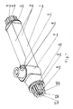
- Fig. 1 shows the side-view of the roller in the axonometric view
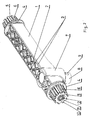
- Fig.2 shows the side-view of the roller from the bottom in the axonometric view
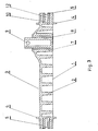
- Fig.3 the side-view of the roller in section
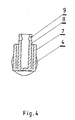
- Fig. 4 the side-view of the roller with the socket section.
- the construction of the squeezing press roller of the cleaning kit e.g., a mop or a flat mop, is lengthwise rectangular-shaped made as one-element plastic construction, consisting of the body 1 , whose cross-section is square-shaped and whose bottom side is open.
- the internal stiffening structure made of intersecting fins 2 slant to the lengthwise body 1 axis and interconnecting body 1 walls 3 , filling the entire space between the walls, and the central part 1 is closed from its both sides with flat and round planes 4 located perpendicular to the lengthwise body 1 axis, and on both body 1 ends are cylinder-shaped tips 5 with fins on the surface in the form of lengthwise projections 6 forming splines, and each tip 5 is located on internal equally arranged lengthwise holders 10 located on the central lengthwise cylinder-shaped mandrel 11 with the central opening 12 .
- the socket 7 for fixing a pipe, manually-pressed by a cleaning person, which socket is not centrally located, and is closer to one round surface 4 , and is perpendicular to lengthwise axis of the body 1 .
- the socket 7 is shaped like the cylinder located in the body 1 .
- Inside the socket 7 centrally located is the mandrel 8 seated in the socket 7 base.
- a pipe is put on the mandrel, which pipe is connected by a clamp located in the mandrel and pipe port 9 to prevent disconnection during operation of the pipe and mandrel 8 .
- the end of the pipe seated in the mandrel 8 is pressed manually by a cleaning person, due to which the press is activated and the mop is squeezed out.
Landscapes
- Cleaning In General (AREA)
- Rolls And Other Rotary Bodies (AREA)
- Cleaning By Liquid Or Steam (AREA)
- Cleaning Implements For Floors, Carpets, Furniture, Walls, And The Like (AREA)
- Treatment Of Fiber Materials (AREA)
- Shaping Of Tube Ends By Bending Or Straightening (AREA)
- Cleaning And De-Greasing Of Metallic Materials By Chemical Methods (AREA)
Abstract
Description
- The subject of this invention is the construction of the squeezing press roller, especially for the squeezing press roller of the cleaning kit, made as one element plastic construction.
- The squeezing press roller which has been known so far is made as aluminum long cylinder-shaped cast, with stopper rings on both ends of the long axis and rectangular-shaped mandrel at the end with square-section. A roller-shaped connection supported by the external flange holding the roller is located closer to one of the rings, and is perpendicular to the lengthwise roller axis.
- A disadvantage of the already known roller is that while wet elements, such as mop or its parts, were squeezed, the roller would frequently get broken or twist over. The device would become damaged, and the roller needed to be replaced. The squeezing press would lose its functions in this way. The rollers were damaged because they could not withstand the bending and twisting forces effecting the roller material, and also because of construction of rollers which was inadequate often as a result of casting technological requirements, yet the main cause was the so-called material micro-shrinkages which formed during aluminum casting of rollers. Those defects cannot be seen externally, and certain specialist equipment would have to be used to detect them in the roller construction, which is related to significant costs. The already known rollers would be mainly damaged due to the effect of bending forces, and the maximum strength of the rollers designed in that way reached the values of 200 to 260 Nm during destruction tests.
- The objective of the invention was to construct a roller which would be free of those defects, and furthermore could be made from high-strength and easy-to-make plastic material.
- According to the invention the roller construction for the squeezing press with the lengthwise-shaped body and the activating pipe mandrel is characterized in that it is made as one-element plastic construction and has lengthwise rectangular-shaped body with the square section and open bottom. Inside the body is the internal stiffening construction consisting of intersecting fins slant to the lengthwise body axis and interconnecting body walls. Flat and round planes perpendicular to the lengthwise body axis close the central part of the body on its both sides. Both ends of the body are ended with cylinder-shaped tips which are finned on the surface in the form of lengthwise projections arranged on the tip surface to form splines. The activating pipe socket is non-centrally located on the body, closer to one of the round planes, perpendicular to the lengthwise axis of the body. The socket is cylinder-shaped and is located in the body, whereas the mandrel seated in the socket base is located centrally inside the cylinder.
- Preferably, both body ends are located on internal equally arranged lengthwise fin holders located on the central lengthwise cylinder-shaped mandrel with central opening.
- Preferably, the internal finning is formed by rectangular open walls with the square section neighboring the external ones with the triangle section.
- Preferably, the socket mandrel is above the upper socket edge and the mandrel has the opening perpendicular to the lengthwise body axis.
- Preferably, the socket is cylinder-shaped with diameter bigger than the body thickness, and the finning covers the external surface of the socket cylinder.
- Preferably, the diameter of flat and round planes is bigger than the body section.
- The advantage of the squeezing press construction made as one-element plastic construction is considerable improvement of its strength. During destruction tests the strength reaches the values of 270 to 300 Nm. Due to the used construction the strength of the socket improved, wherein the roller would be most frequently broken. The construction based on the internal fining meets the strength requirements for bending and twisting. Such construction of the roller eliminated damage to the roller and the necessity of its frequent replacement.
- The example of the subject of the invention is shown on the drawing, where Fig. 1 shows the side-view of the roller in the axonometric view, Fig.2 shows the side-view of the roller from the bottom in the axonometric view, Fig.3 the side-view of the roller in section, and Fig. 4 the side-view of the roller with the socket section.
- The construction of the squeezing press roller of the cleaning kit, e.g., a mop or a flat mop, is lengthwise rectangular-shaped made as one-element plastic construction, consisting of the
body 1, whose cross-section is square-shaped and whose bottom side is open. Inside thebody 1 is located the internal stiffening structure made of intersectingfins 2 slant to thelengthwise body 1 axis and interconnectingbody 1walls 3, filling the entire space between the walls, and thecentral part 1 is closed from its both sides with flat andround planes 4 located perpendicular to thelengthwise body 1 axis, and on bothbody 1 ends are cylinder-shaped tips 5 with fins on the surface in the form oflengthwise projections 6 forming splines, and eachtip 5 is located on internal equally arranged lengthwiseholders 10 located on the central lengthwise cylinder-shaped mandrel 11 with thecentral opening 12. Located on thebody 1 is thesocket 7 for fixing a pipe, manually-pressed by a cleaning person, which socket is not centrally located, and is closer to oneround surface 4, and is perpendicular to lengthwise axis of thebody 1. Thesocket 7 is shaped like the cylinder located in thebody 1. Inside thesocket 7 centrally located is themandrel 8 seated in thesocket 7 base. A pipe is put on the mandrel, which pipe is connected by a clamp located in the mandrel andpipe port 9 to prevent disconnection during operation of the pipe andmandrel 8. The end of the pipe seated in themandrel 8 is pressed manually by a cleaning person, due to which the press is activated and the mop is squeezed out.
Claims (6)
- The construction of the squeezing press roller with the lengthwise body, stopper rings and connection for fixing a pressing pipe is characterized in that the roller is made as one-element plastic construction and has lengthwise rectangular-shaped body (1) with the square section and its bottom side open. Inside the body (1) is located the internal stiffening construction consisting of intersecting fins (2) which is slant to the lengthwise body (1) axis and interconnects walls (3) of the body (1) that fills the entire space between the walls, and the flat and round planes (4) perpendicular to the lengthwise body (1) axis close the central part of the body (1) on its both sides, and on both body ends are cylinder-shaped tips (5) with fins on the surface in the form of lengthwise projections (6) forming splines, and on the body (1) non-centrally located is the socket (7), closer to one round plane (4), perpendicular to the lengthwise axis of the body (1), whereas the socket (7) is shaped like the cylinder located in the body (1), whereas inside the cylinder is centrally located mandrel (8) seated in the socket (7) base.
- The construction of the roller according to claim 1 is characterized in that the tips (5) are located on internal equally arranged lengthwise fin holders (10) located on the central lengthwise cylinder-shaped mandrel (11) with central opening (12),
- The construction of the roller according to claim 1 is characterized in that the internal fins (2) form open rectangular walls with the square section, which walls neighbor the walls with triangle section,
- The construction of the roller according to claim 1 is characterized in that the mandrel (8) is above the upper socket (7) edge and the mandrel (8) has the port (9) perpendicular to the lengthwise body axis (1),
- The construction of the roller according to claim 1 is characterized in that the socket (7) is cylinder-shaped, whose diameter is bigger than the diameter of the body (1), and the inside finning (2) spreads over the external surface of the socket (7),
- The construction of the roller according to claim 1 is characterized in that the diameter of the flat and round planes (4) is bigger than the section of the body (1).
Priority Applications (1)
| Application Number | Priority Date | Filing Date | Title |
|---|---|---|---|
| PL06460008T PL1825799T3 (en) | 2006-02-27 | 2006-03-28 | A squeezing press roller of a cleaning kit |
Applications Claiming Priority (1)
| Application Number | Priority Date | Filing Date | Title |
|---|---|---|---|
| PL379069A PL205371B1 (en) | 2006-02-27 | 2006-02-27 | Squeezing press roller of the cleaning up equipment |
Publications (2)
| Publication Number | Publication Date |
|---|---|
| EP1825799A1 true EP1825799A1 (en) | 2007-08-29 |
| EP1825799B1 EP1825799B1 (en) | 2010-06-30 |
Family
ID=38153844
Family Applications (1)
| Application Number | Title | Priority Date | Filing Date |
|---|---|---|---|
| EP06460008A Expired - Lifetime EP1825799B1 (en) | 2006-02-27 | 2006-03-28 | A squeezing press roller of a cleaning kit |
Country Status (6)
| Country | Link |
|---|---|
| EP (1) | EP1825799B1 (en) |
| AT (1) | ATE472288T1 (en) |
| DE (1) | DE602006015157D1 (en) |
| ES (1) | ES2347813T3 (en) |
| PL (2) | PL205371B1 (en) |
| PT (1) | PT1825799E (en) |
Citations (5)
| Publication number | Priority date | Publication date | Assignee | Title |
|---|---|---|---|---|
| BE482699A (en) * | ||||
| US1517187A (en) * | 1922-12-13 | 1924-11-25 | Thomas L Bonsall | Mop wringer |
| US3074097A (en) * | 1960-06-01 | 1963-01-22 | Beacon Plastic And Metal Produ | Combination bucket and wringer |
| US4912804A (en) * | 1988-06-13 | 1990-04-03 | Fr. Ditlevsens Eftr. A/S | Mop wringer |
| WO1994026159A1 (en) * | 1993-05-07 | 1994-11-24 | Sergio Cervellin | Squeezing device for flat mops |
-
2006
- 2006-02-27 PL PL379069A patent/PL205371B1/en unknown
- 2006-03-28 PT PT06460008T patent/PT1825799E/en unknown
- 2006-03-28 ES ES06460008T patent/ES2347813T3/en not_active Expired - Lifetime
- 2006-03-28 DE DE602006015157T patent/DE602006015157D1/en not_active Expired - Lifetime
- 2006-03-28 AT AT06460008T patent/ATE472288T1/en not_active IP Right Cessation
- 2006-03-28 EP EP06460008A patent/EP1825799B1/en not_active Expired - Lifetime
- 2006-03-28 PL PL06460008T patent/PL1825799T3/en unknown
Patent Citations (5)
| Publication number | Priority date | Publication date | Assignee | Title |
|---|---|---|---|---|
| BE482699A (en) * | ||||
| US1517187A (en) * | 1922-12-13 | 1924-11-25 | Thomas L Bonsall | Mop wringer |
| US3074097A (en) * | 1960-06-01 | 1963-01-22 | Beacon Plastic And Metal Produ | Combination bucket and wringer |
| US4912804A (en) * | 1988-06-13 | 1990-04-03 | Fr. Ditlevsens Eftr. A/S | Mop wringer |
| WO1994026159A1 (en) * | 1993-05-07 | 1994-11-24 | Sergio Cervellin | Squeezing device for flat mops |
Also Published As
| Publication number | Publication date |
|---|---|
| DE602006015157D1 (en) | 2010-08-12 |
| PL205371B1 (en) | 2010-04-30 |
| PT1825799E (en) | 2010-09-23 |
| PL1825799T3 (en) | 2010-11-30 |
| PL379069A1 (en) | 2007-09-03 |
| ES2347813T3 (en) | 2010-11-04 |
| ATE472288T1 (en) | 2010-07-15 |
| EP1825799B1 (en) | 2010-06-30 |
Similar Documents
| Publication | Publication Date | Title |
|---|---|---|
| KR101102531B1 (en) | One-touch quick coupler for reinforcing bars | |
| CN102405558B (en) | Terminal fittings and wires with terminal fittings | |
| EP0944130A3 (en) | Crimp connection | |
| BR112012019274B1 (en) | connection structure and connector | |
| EP1058040A3 (en) | Clamp for two pipes | |
| EP2186638A3 (en) | Storage for printing plates | |
| EP2698626A3 (en) | Reaction container | |
| AU4620701A (en) | Holder for fastening a mop at the end of a handle | |
| EP1825799A1 (en) | A squeezing press roller of a cleaning kit | |
| SE539003C2 (en) | Distinct stops of a compression wedge | |
| FR3021885A1 (en) | DEVICE FOR REMOVING THE FALLS OF TOOLS FORMED IN A STACKING PRESS, COMPRISING AT LEAST ONE VIBRATING CHUTE | |
| PL63850Y1 (en) | Design of squeezing press roller of the cleaning up equipment | |
| EP1167853A2 (en) | Pressure fitting for tubes | |
| ES2200985T3 (en) | PRESSING MEMBRANE OF RUBBER TYPE ELASTIC MATERIAL. | |
| ES2358242T3 (en) | MOUNTING SYSTEM TO JOIN COATING PANELS TO VERTICAL ELEMENTS. | |
| CN210996232U (en) | A steel bar sleeve extrusion pliers and an extrusion connection machine with the same | |
| CN103741892A (en) | A metal roof lock and clamps for clamping the lock | |
| CN206561743U (en) | The clipping drawing board of indoor design specialty | |
| EP3489610A1 (en) | Heat exchanger | |
| CN221676930U (en) | Stainless steel pipe fitting clamping jaw | |
| EP2181748A3 (en) | Hydrodynamic separator for cleaning a fluid stream | |
| CN211587989U (en) | Stainless steel wire lead chain convenient to disassemble and assemble | |
| US1526601A (en) | Packing-ring compressor sleeve | |
| CN105264239B (en) | Tightening member | |
| EP1881577A1 (en) | Fastening plug for fastening a support unit for electrical installation material to a cable channel |
Legal Events
| Date | Code | Title | Description |
|---|---|---|---|
| PUAI | Public reference made under article 153(3) epc to a published international application that has entered the european phase |
Free format text: ORIGINAL CODE: 0009012 |
|
| AK | Designated contracting states |
Kind code of ref document: A1 Designated state(s): AT BE BG CH CY CZ DE DK EE ES FI FR GB GR HU IE IS IT LI LT LU LV MC NL PL PT RO SE SI SK TR |
|
| AX | Request for extension of the european patent |
Extension state: AL BA HR MK YU |
|
| 17P | Request for examination filed |
Effective date: 20080125 |
|
| AKX | Designation fees paid |
Designated state(s): AT BE BG CH CY CZ DE DK EE ES FI FR GB GR HU IE IS IT LI LT LU LV MC NL PL PT RO SE SI SK TR |
|
| GRAP | Despatch of communication of intention to grant a patent |
Free format text: ORIGINAL CODE: EPIDOSNIGR1 |
|
| GRAS | Grant fee paid |
Free format text: ORIGINAL CODE: EPIDOSNIGR3 |
|
| GRAA | (expected) grant |
Free format text: ORIGINAL CODE: 0009210 |
|
| AK | Designated contracting states |
Kind code of ref document: B1 Designated state(s): AT BE BG CH CY CZ DE DK EE ES FI FR GB GR HU IE IS IT LI LT LU LV MC NL PL PT RO SE SI SK TR |
|
| REG | Reference to a national code |
Ref country code: GB Ref legal event code: FG4D Ref country code: CH Ref legal event code: EP |
|
| REG | Reference to a national code |
Ref country code: IE Ref legal event code: FG4D |
|
| REF | Corresponds to: |
Ref document number: 602006015157 Country of ref document: DE Date of ref document: 20100812 Kind code of ref document: P |
|
| REG | Reference to a national code |
Ref country code: PT Ref legal event code: SC4A Free format text: AVAILABILITY OF NATIONAL TRANSLATION Effective date: 20100916 |
|
| REG | Reference to a national code |
Ref country code: NL Ref legal event code: VDEP Effective date: 20100630 |
|
| PG25 | Lapsed in a contracting state [announced via postgrant information from national office to epo] |
Ref country code: SE Free format text: LAPSE BECAUSE OF FAILURE TO SUBMIT A TRANSLATION OF THE DESCRIPTION OR TO PAY THE FEE WITHIN THE PRESCRIBED TIME-LIMIT Effective date: 20100630 Ref country code: LT Free format text: LAPSE BECAUSE OF FAILURE TO SUBMIT A TRANSLATION OF THE DESCRIPTION OR TO PAY THE FEE WITHIN THE PRESCRIBED TIME-LIMIT Effective date: 20100630 |
|
| REG | Reference to a national code |
Ref country code: ES Ref legal event code: FG2A Ref document number: 2347813 Country of ref document: ES Kind code of ref document: T3 |
|
| LTIE | Lt: invalidation of european patent or patent extension |
Effective date: 20100630 |
|
| PG25 | Lapsed in a contracting state [announced via postgrant information from national office to epo] |
Ref country code: FI Free format text: LAPSE BECAUSE OF FAILURE TO SUBMIT A TRANSLATION OF THE DESCRIPTION OR TO PAY THE FEE WITHIN THE PRESCRIBED TIME-LIMIT Effective date: 20100630 Ref country code: AT Free format text: LAPSE BECAUSE OF FAILURE TO SUBMIT A TRANSLATION OF THE DESCRIPTION OR TO PAY THE FEE WITHIN THE PRESCRIBED TIME-LIMIT Effective date: 20100630 Ref country code: LV Free format text: LAPSE BECAUSE OF FAILURE TO SUBMIT A TRANSLATION OF THE DESCRIPTION OR TO PAY THE FEE WITHIN THE PRESCRIBED TIME-LIMIT Effective date: 20100630 Ref country code: SI Free format text: LAPSE BECAUSE OF FAILURE TO SUBMIT A TRANSLATION OF THE DESCRIPTION OR TO PAY THE FEE WITHIN THE PRESCRIBED TIME-LIMIT Effective date: 20100630 |
|
| REG | Reference to a national code |
Ref country code: PL Ref legal event code: T3 |
|
| PG25 | Lapsed in a contracting state [announced via postgrant information from national office to epo] |
Ref country code: GR Free format text: LAPSE BECAUSE OF FAILURE TO SUBMIT A TRANSLATION OF THE DESCRIPTION OR TO PAY THE FEE WITHIN THE PRESCRIBED TIME-LIMIT Effective date: 20101001 |
|
| PG25 | Lapsed in a contracting state [announced via postgrant information from national office to epo] |
Ref country code: EE Free format text: LAPSE BECAUSE OF FAILURE TO SUBMIT A TRANSLATION OF THE DESCRIPTION OR TO PAY THE FEE WITHIN THE PRESCRIBED TIME-LIMIT Effective date: 20100630 Ref country code: NL Free format text: LAPSE BECAUSE OF FAILURE TO SUBMIT A TRANSLATION OF THE DESCRIPTION OR TO PAY THE FEE WITHIN THE PRESCRIBED TIME-LIMIT Effective date: 20100630 |
|
| PG25 | Lapsed in a contracting state [announced via postgrant information from national office to epo] |
Ref country code: BE Free format text: LAPSE BECAUSE OF FAILURE TO SUBMIT A TRANSLATION OF THE DESCRIPTION OR TO PAY THE FEE WITHIN THE PRESCRIBED TIME-LIMIT Effective date: 20100630 Ref country code: IS Free format text: LAPSE BECAUSE OF FAILURE TO SUBMIT A TRANSLATION OF THE DESCRIPTION OR TO PAY THE FEE WITHIN THE PRESCRIBED TIME-LIMIT Effective date: 20101030 Ref country code: CY Free format text: LAPSE BECAUSE OF FAILURE TO SUBMIT A TRANSLATION OF THE DESCRIPTION OR TO PAY THE FEE WITHIN THE PRESCRIBED TIME-LIMIT Effective date: 20100630 Ref country code: RO Free format text: LAPSE BECAUSE OF FAILURE TO SUBMIT A TRANSLATION OF THE DESCRIPTION OR TO PAY THE FEE WITHIN THE PRESCRIBED TIME-LIMIT Effective date: 20100630 Ref country code: CZ Free format text: LAPSE BECAUSE OF FAILURE TO SUBMIT A TRANSLATION OF THE DESCRIPTION OR TO PAY THE FEE WITHIN THE PRESCRIBED TIME-LIMIT Effective date: 20100630 Ref country code: SK Free format text: LAPSE BECAUSE OF FAILURE TO SUBMIT A TRANSLATION OF THE DESCRIPTION OR TO PAY THE FEE WITHIN THE PRESCRIBED TIME-LIMIT Effective date: 20100630 |
|
| PG25 | Lapsed in a contracting state [announced via postgrant information from national office to epo] |
Ref country code: DK Free format text: LAPSE BECAUSE OF FAILURE TO SUBMIT A TRANSLATION OF THE DESCRIPTION OR TO PAY THE FEE WITHIN THE PRESCRIBED TIME-LIMIT Effective date: 20100630 |
|
| PLBE | No opposition filed within time limit |
Free format text: ORIGINAL CODE: 0009261 |
|
| STAA | Information on the status of an ep patent application or granted ep patent |
Free format text: STATUS: NO OPPOSITION FILED WITHIN TIME LIMIT |
|
| 26N | No opposition filed |
Effective date: 20110331 |
|
| REG | Reference to a national code |
Ref country code: DE Ref legal event code: R097 Ref document number: 602006015157 Country of ref document: DE Effective date: 20110330 |
|
| PG25 | Lapsed in a contracting state [announced via postgrant information from national office to epo] |
Ref country code: MC Free format text: LAPSE BECAUSE OF NON-PAYMENT OF DUE FEES Effective date: 20110331 |
|
| REG | Reference to a national code |
Ref country code: CH Ref legal event code: PL |
|
| REG | Reference to a national code |
Ref country code: IE Ref legal event code: MM4A |
|
| PG25 | Lapsed in a contracting state [announced via postgrant information from national office to epo] |
Ref country code: IE Free format text: LAPSE BECAUSE OF NON-PAYMENT OF DUE FEES Effective date: 20110328 Ref country code: LI Free format text: LAPSE BECAUSE OF NON-PAYMENT OF DUE FEES Effective date: 20110331 Ref country code: CH Free format text: LAPSE BECAUSE OF NON-PAYMENT OF DUE FEES Effective date: 20110331 |
|
| PG25 | Lapsed in a contracting state [announced via postgrant information from national office to epo] |
Ref country code: LU Free format text: LAPSE BECAUSE OF NON-PAYMENT OF DUE FEES Effective date: 20110328 |
|
| PG25 | Lapsed in a contracting state [announced via postgrant information from national office to epo] |
Ref country code: TR Free format text: LAPSE BECAUSE OF FAILURE TO SUBMIT A TRANSLATION OF THE DESCRIPTION OR TO PAY THE FEE WITHIN THE PRESCRIBED TIME-LIMIT Effective date: 20100630 Ref country code: BG Free format text: LAPSE BECAUSE OF FAILURE TO SUBMIT A TRANSLATION OF THE DESCRIPTION OR TO PAY THE FEE WITHIN THE PRESCRIBED TIME-LIMIT Effective date: 20100930 |
|
| PG25 | Lapsed in a contracting state [announced via postgrant information from national office to epo] |
Ref country code: HU Free format text: LAPSE BECAUSE OF FAILURE TO SUBMIT A TRANSLATION OF THE DESCRIPTION OR TO PAY THE FEE WITHIN THE PRESCRIBED TIME-LIMIT Effective date: 20100630 |
|
| REG | Reference to a national code |
Ref country code: FR Ref legal event code: PLFP Year of fee payment: 11 |
|
| REG | Reference to a national code |
Ref country code: FR Ref legal event code: PLFP Year of fee payment: 12 |
|
| REG | Reference to a national code |
Ref country code: FR Ref legal event code: PLFP Year of fee payment: 13 |
|
| PGFP | Annual fee paid to national office [announced via postgrant information from national office to epo] |
Ref country code: PT Payment date: 20200203 Year of fee payment: 15 Ref country code: IT Payment date: 20200304 Year of fee payment: 15 Ref country code: DE Payment date: 20200324 Year of fee payment: 15 |
|
| PGFP | Annual fee paid to national office [announced via postgrant information from national office to epo] |
Ref country code: FR Payment date: 20200310 Year of fee payment: 15 |
|
| PGFP | Annual fee paid to national office [announced via postgrant information from national office to epo] |
Ref country code: ES Payment date: 20200414 Year of fee payment: 15 |
|
| PGFP | Annual fee paid to national office [announced via postgrant information from national office to epo] |
Ref country code: GB Payment date: 20200408 Year of fee payment: 15 |
|
| REG | Reference to a national code |
Ref country code: DE Ref legal event code: R119 Ref document number: 602006015157 Country of ref document: DE |
|
| GBPC | Gb: european patent ceased through non-payment of renewal fee |
Effective date: 20210328 |
|
| PG25 | Lapsed in a contracting state [announced via postgrant information from national office to epo] |
Ref country code: PT Free format text: LAPSE BECAUSE OF NON-PAYMENT OF DUE FEES Effective date: 20210928 |
|
| PG25 | Lapsed in a contracting state [announced via postgrant information from national office to epo] |
Ref country code: GB Free format text: LAPSE BECAUSE OF NON-PAYMENT OF DUE FEES Effective date: 20210328 Ref country code: FR Free format text: LAPSE BECAUSE OF NON-PAYMENT OF DUE FEES Effective date: 20210331 Ref country code: DE Free format text: LAPSE BECAUSE OF NON-PAYMENT OF DUE FEES Effective date: 20211001 |
|
| PG25 | Lapsed in a contracting state [announced via postgrant information from national office to epo] |
Ref country code: IT Free format text: LAPSE BECAUSE OF NON-PAYMENT OF DUE FEES Effective date: 20210328 |
|
| REG | Reference to a national code |
Ref country code: ES Ref legal event code: FD2A Effective date: 20220524 |
|
| PG25 | Lapsed in a contracting state [announced via postgrant information from national office to epo] |
Ref country code: ES Free format text: LAPSE BECAUSE OF NON-PAYMENT OF DUE FEES Effective date: 20210329 |
|
| PGFP | Annual fee paid to national office [announced via postgrant information from national office to epo] |
Ref country code: PL Payment date: 20240123 Year of fee payment: 19 |