EP1825551B1 - Fuel cell with hydrogen internal recirculation - Google Patents
Fuel cell with hydrogen internal recirculation Download PDFInfo
- Publication number
- EP1825551B1 EP1825551B1 EP05850248A EP05850248A EP1825551B1 EP 1825551 B1 EP1825551 B1 EP 1825551B1 EP 05850248 A EP05850248 A EP 05850248A EP 05850248 A EP05850248 A EP 05850248A EP 1825551 B1 EP1825551 B1 EP 1825551B1
- Authority
- EP
- European Patent Office
- Prior art keywords
- hydrogen
- cell
- fuel cell
- transfer
- compartment
- Prior art date
- Legal status (The legal status is an assumption and is not a legal conclusion. Google has not performed a legal analysis and makes no representation as to the accuracy of the status listed.)
- Expired - Lifetime
Links
Images



Classifications
-
- H—ELECTRICITY
- H01—ELECTRIC ELEMENTS
- H01M—PROCESSES OR MEANS, e.g. BATTERIES, FOR THE DIRECT CONVERSION OF CHEMICAL ENERGY INTO ELECTRICAL ENERGY
- H01M8/00—Fuel cells; Manufacture thereof
- H01M8/04—Auxiliary arrangements, e.g. for control of pressure or for circulation of fluids
- H01M8/04082—Arrangements for control of reactant parameters, e.g. pressure or concentration
- H01M8/04089—Arrangements for control of reactant parameters, e.g. pressure or concentration of gaseous reactants
- H01M8/04097—Arrangements for control of reactant parameters, e.g. pressure or concentration of gaseous reactants with recycling of the reactants
-
- B—PERFORMING OPERATIONS; TRANSPORTING
- B01—PHYSICAL OR CHEMICAL PROCESSES OR APPARATUS IN GENERAL
- B01D—SEPARATION
- B01D53/00—Separation of gases or vapours; Recovering vapours of volatile solvents from gases; Chemical or biological purification of waste gases, e.g. engine exhaust gases, smoke, fumes, flue gases, aerosols
- B01D53/32—Separation of gases or vapours; Recovering vapours of volatile solvents from gases; Chemical or biological purification of waste gases, e.g. engine exhaust gases, smoke, fumes, flue gases, aerosols by electrical effects other than those provided for in group B01D61/00
-
- H—ELECTRICITY
- H01—ELECTRIC ELEMENTS
- H01M—PROCESSES OR MEANS, e.g. BATTERIES, FOR THE DIRECT CONVERSION OF CHEMICAL ENERGY INTO ELECTRICAL ENERGY
- H01M8/00—Fuel cells; Manufacture thereof
- H01M8/06—Combination of fuel cells with means for production of reactants or for treatment of residues
- H01M8/0606—Combination of fuel cells with means for production of reactants or for treatment of residues with means for production of gaseous reactants
- H01M8/065—Combination of fuel cells with means for production of reactants or for treatment of residues with means for production of gaseous reactants by dissolution of metals or alloys; by dehydriding metallic substances
-
- H—ELECTRICITY
- H01—ELECTRIC ELEMENTS
- H01M—PROCESSES OR MEANS, e.g. BATTERIES, FOR THE DIRECT CONVERSION OF CHEMICAL ENERGY INTO ELECTRICAL ENERGY
- H01M8/00—Fuel cells; Manufacture thereof
- H01M8/04—Auxiliary arrangements, e.g. for control of pressure or for circulation of fluids
- H01M8/04223—Auxiliary arrangements, e.g. for control of pressure or for circulation of fluids during start-up or shut-down; Depolarisation or activation, e.g. purging; Means for short-circuiting defective fuel cells
- H01M8/04231—Purging of the reactants
-
- Y—GENERAL TAGGING OF NEW TECHNOLOGICAL DEVELOPMENTS; GENERAL TAGGING OF CROSS-SECTIONAL TECHNOLOGIES SPANNING OVER SEVERAL SECTIONS OF THE IPC; TECHNICAL SUBJECTS COVERED BY FORMER USPC CROSS-REFERENCE ART COLLECTIONS [XRACs] AND DIGESTS
- Y02—TECHNOLOGIES OR APPLICATIONS FOR MITIGATION OR ADAPTATION AGAINST CLIMATE CHANGE
- Y02E—REDUCTION OF GREENHOUSE GAS [GHG] EMISSIONS, RELATED TO ENERGY GENERATION, TRANSMISSION OR DISTRIBUTION
- Y02E60/00—Enabling technologies; Technologies with a potential or indirect contribution to GHG emissions mitigation
- Y02E60/30—Hydrogen technology
- Y02E60/50—Fuel cells
-
- Y—GENERAL TAGGING OF NEW TECHNOLOGICAL DEVELOPMENTS; GENERAL TAGGING OF CROSS-SECTIONAL TECHNOLOGIES SPANNING OVER SEVERAL SECTIONS OF THE IPC; TECHNICAL SUBJECTS COVERED BY FORMER USPC CROSS-REFERENCE ART COLLECTIONS [XRACs] AND DIGESTS
- Y10—TECHNICAL SUBJECTS COVERED BY FORMER USPC
- Y10S—TECHNICAL SUBJECTS COVERED BY FORMER USPC CROSS-REFERENCE ART COLLECTIONS [XRACs] AND DIGESTS
- Y10S204/00—Chemistry: electrical and wave energy
- Y10S204/04—Electrolysis cell combined with fuel cell
Definitions
- Fuel cells are devices characterised by the possibility of converting the chemical energy of combination of a fuel and an oxidant directly into electrical energy. For this reason, fuel cells are not subject to the known limitation of Carnot's cycle, based on an intermediate thermal stage, and are therefore characterised by a high energy efficiency.
- ion-exchange membrane fuel cells are considered of peculiar interest for automotive and for medium-small size residential generation applications, due to the compactness, the relative operating simplicity and the absence of important decay phenomena in the construction materials.
- the oxidant normally employed in ion-exchange membrane fuel cells is air, at near-atmospheric pressure or under a pressure not exceeding 3-4 bar.
- the fuel fed at about the same pressure as air, may consist of a gas containing hydrogen together with other components such as carbon dioxide and nitrogen, usually obtained by conversion of hydrocarbons or alcohols in reactors known as modifiers, among which steam reformers and autothermal reformers are the most common.
- Such type of gas is affected by two important drawbacks, namely the presence of residual traces of carbon monoxide, which is in fact an unavoidable intermediate compound in the conversion of hydrocarbons or alcohols into hydrogen, and the need of purging remarkable quantities of gas from the fuel cell to prevent an intolerable build-up of carbon monoxide and nitrogen in its interior.
- Carbon monoxide is capable, even as traces, to block the conventional platinum catalysts used in fuel cell electrodes forcing the use of special alloys, which are more expensive and whose reliability is still to be proved.
- Considerable purge flow-rates pose the problem of the utilisation of the hydrogen contained therein, for instance as fuel of the steam reforming reactor in automotive applications or as fuel for the generation of thermal energy in residential-type applications, in both cases with sensible complications of the overall system.
- fuel cells may be fed with pure hydrogen, obtainable in particular cases by electrolysis or more generally from the same gas mixtures produced in steam reforming or autothermal reforming reactors through a passage across suitable separation units, based for instance on metal or polymer selective membranes or on absorbing materials such as certain types of molecular sieves.
- the fuel cell feed on pure hydrogen allows using the conventional platinum catalysts whose working reliability over an extended period of time is widely demonstrated and in principle to operate with unit stoichiometry flow-rates, in other words with flow-rates exactly corresponding to the amount of hydrogen consumed by the output current. Nevertheless this operating mode, known to those skilled in the art as "dead-end mode", introduces at least two kinds of problems.
- the former problem is associated to the capacity of the nitrogen contained in the air on the fuel cell cathode compartment to diffuse across the ion-exchange membrane, progressively building up in the stagnant hydrogen present on the anode side, particularly near the bottom: the consequent hydrogen dilution determines a preferential distribution of the output current in those zones with a less relevant presence of nitrogen, with a consequent performance decay and a possible lifetime decrease.
- the latter problem is caused by the presence of liquid water formed by condensation of the water vapour transported by diffusion from the cathode compartment, similarly to what occurs with nitrogen.
- the progressive liquid water build-up leads to flooding phenomena of the porous anode catalyst structure, with an additional performance decay which sums up to the one induced by the accumulation of nitrogen.
- the success of the method is based on the assumption that the overall hydrogen flow-rate consisting of the feed and the recycle be apportioned in a substantially uniform fashion over the multiplicity of fuel cells which must be assembled to obtained the high voltages normally required by the user appliances: since i the passage sections for the feeding of gases to the individual fuel cells have a random distribution around the design value, due to the constructive tolerances and of the inevitable, albeit marginal, imperfections in the assembly of the various components, the hydrogen flow-rate may be lower in some cells with respect to the average value, which makes the extraction of the liquid water from the anode compartment more difficult.
- the individual fuel cells in which this negative situation takes place are consequently characterised by lower performances, which in extreme cases may even lead the whole stack to be put out of service. This problem, hard to counteract in a system consisting of a multiplicity of components, moreover adds up to the negative aspect of the energy consumption of the recirculation pump.
- US 2004/0142215 proposes to replace the external recirculation pump with at least one hydrogen-transfer electrochemical cell: this type of cell has a design equivalent to that of the fuel cell, and includes an ion-exchange membrane on whose faces two electrodes, anode and cathode, are applied, both containing a catalyst suitable for hydrogen ionisation to protons and for proton recombination to hydrogen. During operation, the hydrogen-transfer cell anode compartment is fed with the hydrogen exhaust of the fuel cell.
- the anode provides to the ionisation of hydrogen to protons which migrate across the membrane and are recombined on the opposite side at the cathode, producing pure hydrogen.
- This product hydrogen is added to the main feed, giving thus rise to the same kind of external recycling which would be obtained by installing a mechanical pump: the ratio between number of hydrogen-transfer cells and number of fuel cells defines the recirculation rate.
- the hydrogen-transfer cells installed as a separate module distinct from the fuel cell one or laminated with the fuel cells in a single assembly, may be fed with an external electrical source or otherwise with a portion of the fuel cell electric output.
- the device of US 2004/0142215 has the merit of eliminating a delicate component such as the recirculation pump with its rotating parts, while retaining the above seen inconveniences of possible malfunctioning of some individual cells presenting reduced passage sections and lower internal hydrogen flow-rates.
- the present invention has the scope to overcome the inconveniences of the prior art providing a novel unit comprising an ion-exchange membrane fuel cell and a hydrogen-transfer electrochemical cell.
- the unit of the invention is comprised of the membrane fuel cell integrated with the hydrogen-transfer cell.
- the unit formed by the membrane fuel cell integrated with the hydrogen-transfer cell is enclosed between two bipolar plates and the internal components of the fuel cell are laminated together with the internal components of the hydrogen-transfer cell.
- the unit is formed by the membrane fuel cell associated with the hydrogen-transfer cell and is enclosed between two bipolar plates with the internal components of the fuel cell kept separate from the internal components of the hydrogen-transfer cell by means of a third intermediate bipolar plate.
- the fuel cell hydrogen exhaust is introduced into the hydrogen-transfer cell and the hydrogen produced in the hydrogen-transfer cell is internally recycled to the fuel cell anode compartment.
- a lesser quantity of the hydrogen discharged by the membrane fuel cell is vented to the external environment.
- the ratio of the flow-rate of hydrogen fed to the fuel cell to the flow-rate of pure hydrogen generated by the hydrogen-transfer cell is unitary, in other words the fraction of hydrogen feed produced at the transfer cell and recycled to the fuel cell is equal to half of the overall fuel cell anodic hydrogen feed.
- a multiplicity of units each formed by a membrane fuel cell integrated or mechanically associated with a hydrogen-transfer electrochemical cell, is assembled to make up a stack capable of producing electrical energy at high voltage.
- the present invention provides a new internal hydrogen recirculation system in an ion-exchange membrane fuel cell based on a unit formed by common lamination of an ion-exchange membrane fuel cell with an electrochemical ion-exchange membrane hydrogen-transfer cell (hydrogen-transfer cell in the following).
- the unit of the present invention comprises a fuel cell co-laminated and integrated or mechanically associated with a hydrogen-transfer cell giving rise to a novel internal recirculation of hydrogen.
- FIG. 1 The lateral section of a fuel cell internal structure is sketched in figure 1 , wherein (1) identifies the fuel cell in its entirety and wherein (2) indicates the conductive bipolar plates enclosing the internal components, (3) the ion-exchange membrane, (4) and (5) respectively the anode and the cathode, (6) and (7) the current collectors also taking the role of reactant gas distributors, (8) the perimetrical gaskets preventing the reactant gases to escape to the external environment, (9) and (10) the ducts contained, according to a possible embodiment, in the gaskets (8) for the feed/extraction of hydrogen and air respectively, (11) the user load of the output electrical energy.
- this type of fuel cell is subject to performance decay as a consequence of a progressive build-up of nitrogen and liquid water which diffuse from the cathodic compartment across the membrane.
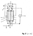
- FIG. 2 A first solution to this problem proposed by the prior art is indicated in figure 2 : the hydrogen (12) discharged in the manifold (13) by the stack (14) of fuel cells (1), limited to two for simplicity of illustration, is sucked in by the mechanical pump (15) and sent back under a suitable pressure into the distributing manifold (16), and thence to the anode compartments of the fuel cells (1).
- the hydrogen feed (17) is connected in its turn to the distributing manifold (16).
- the air feed (18) is sent to the distributing manifold (19) and thence to the cathode compartments of the fuel cells (1), the air discharged from the cathode compartments of the fuel cells (1) is collected in the manifold (20) and thence vented to the external environment.
- the high hydrogen flow-rate allows maintaining the nitrogen concentration at low levels and preventing liquid water build-ups on the fuel cell (1) anode compartment. Nevertheless, as a consequence of hydrogen apportionment defects from the distributing manifold (16) to the anode compartments of the individual fuel cells due to the production tolerance of the components and to assemblage irregularities particularly when the stacks (14) comprise a multiplicity of fuel cells, as normally occurs in the practice, the hydrogen flow-rates in some fuel cells may be sensibly reduced with respect to the average project value, to such an extent as to reestablish the phenomena of nitrogen enrichment and especially of liquid water build-up. For simplicity of illustration in figure 2 the fuel cells stack cooling circuits required to maintain the operating temperatures in the approximate range of 60 - 100°C are not shown. The same simplification is applied to the stacks of figures 4 , 5 , 6 and 7 .
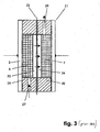
- Figure 3 represents a sketch of a lateral section of a hydrogen-transfer electrochemical cell as known in the prior art: in particular (21) indicates the cell in its entirety, (2) the two bipolar plates, equivalent to those described for the fuel cell of figure 1 , (6) and (7) two current collectors also functioning as gas distributors, also equivalent to the current collectors described for the fuel cell of figure 1 , (22) an ion-exchange membrane, (23) and (24) respectively the anode and the cathode, (25) and (26) the perimetrical gaskets for sealing the gases toward the external environment respectively provided with feed ducts for the hydrogen to be recycled (27) and with hydrogen discharge ducts (28) under a suitable pressure to be sent to the recycle.
- the hydrogen fed through (27) is ionised on the anode (23) with generation of protons which migrate across the membrane (22) to the cathode (24): on the cathode (24), the protons are again converted into hydrogen.
- the overall flux hydrogen ⁇ protons ⁇ hydrogen is indicated by the arrows.
- the present invention is directed to solve the problem of nitrogen and liquid water build-up on the anode compartment of membrane fuel cells fed with pure hydrogen overcoming the drawbacks of the prior art.
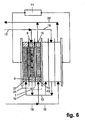
- a first embodiment of the invention is represented in figure 6 , which sketches a side-view of a stack comprising, only for the sake of graphic simplification, two units each consisting of a fuel cell (1) of the type of figure 1 co-laminated and integrated with a hydrogen-transfer cell (21) of figure 3 .
- the side-view of the stack is partially represented in section and shows the integration in accordance with the invention between the components of a hydrogen-transfer cell (21) and an adjacent fuel cell (1): in particular, the cathodic current collector of the hydrogen-transfer cell also constitutes the fuel cell anodic current collector and hence the hydrogen-transfer cell (21) cathode compartment acts as the fuel cell (1) anode compartment.
- the gap comprised between two consecutive bipolar plates results subdivided into three portions, respectively, proceeding from left to right: hydrogen-transfer cell anode compartment; hydrogen-transfer cell cathode compartment coinciding with the fuel cell anode compartment; and fuel cell cathode compartment.
- the pure hydrogen feed (17) is introduced into the distributing manifold (16) and thence in the fuel cell (1) anode compartment.
- the hydrogen (12) discharged from the fuel cells into the manifold (13) is sucked in by the hydrogen-transfer cells and ionised to protons on the anode (23). Protons migrate across the membrane (22) and are reconverted to hydrogen at the cathode (24).
- the hydrogen formed at the cathode (24) is not sent to the external distributing manifold (16), as was the case of the prior art, but is instead mixed to the hydrogen feed coming from the distributing manifold (16) directly inside the fuel cell: in this way a safe hydrogen recirculation is achieved depending only on the electric current crossing the stack, by no means affected by possible problems of distribution of the gas flow associated with production tolerances or assembly inaccuracies.
- FIG 7 A second embodiment of the invention is represented in figure 7 , which sketches a side-view of a stack comprising two units, each consisting of a fuel cell (1) of the type of figure 1 mechanically associated by common lamination with a hydrogen-transfer electrochemical cell (21) of figure 3 .
- the partial section of the side-view shows that the hydrogen-transfer cell (21) and the adjacent fuel cell (1), comprised between two external bipolar plates, maintain their identity being kept separate by a further intermediate bipolar plate.
- the integration between the hydrogen-transfer cell and the fuel cell is of functional type: the hydrogen produced at the cathode (24) of the hydrogen-transfer cell is in fact injected into the fuel cell anode compartment through a series of aligned holes, indicated as (29), on the intermediate bipolar plate in particular, the recycled hydrogen is not sent to the external distributing manifold (16) as occurs in the prior art.
- an internal hydrogen recycle not affected by possible problems of bad distribution associated the with production tolerance of the various components and with assembly inaccuracies is obtained.
- a similar result might be obtained with an alternative internal design based on appropriate ducts, not shown in the figure, obtained inside the gaskets (26) and (8) coupled to corresponding holes made on the intermediate bipolar plate.
- the flux: hydrogen ⁇ protons ⁇ hydrogen on the hydrogen-transfer cell anode compartment ⁇ holes on the intermediate bipolar plate ⁇ hydrogen on the fuel cell anode compartment is indicated by the arrows.
- the stack according to the invention consisting of fuel cells co-laminated and integrated or mechanically associated with hydrogen-transfer electrochemical cells is certainly characterised by higher volume and weight than those typical of the stack only comprising fuel cells, and at first sight it may seem penalised in automotive applications wherein volumes and weights must be evidently minimised.
- the stack of the invention is provided with hydrogen internal recycle, therefore allowing to get rid of the external mechanical pump with the relevant connections and flow-rate regulations, so that the effective overall bulks and weights are not substantially changed.
- the operative reliability of the stack of the invention is certainly higher since the stack is practically a solid-state device consisting of fixed parts only, and therefore free of the rotating parts of the mechanical recirculation pump.
- the stack of the invention finally allows particularly simplified regulations: as in fact the hydrogen-transfer cells are connected to the fuel cells in electrical series, the stack current output to the electrical user loads also determines the hydrogen recycle flow-rate. Moreover, since the output current also determines the hydrogen feed flow-rate, the ratio between the two feed and recycle flow-rates is always constant and equal to 1. Conversely, in the case of the conventional systems comprising the external recycle mechanical pump, it is necessary to send a signal proportional to the output current to a control device which consequently provides for the regulation of the rotating speed of the electric engine associated with the pump.
- a further objection which could be raised against the stack of the invention regards the required investment, particularly as concerns the anode - membrane - cathode assemblies of the hydrogen-transfer electrochemical cells which are in the same amount as the equivalent fuel cell assemblies.
- the latter are in fact rather expensive components as they have to make use of perfluorinated membranes, the only one known for the time being which ensure an adequate chemical inertia toward the aggressive radical intermediates formed on the cathode by the reduction of the oxygen of air.
- the oxygen reaction rate becomes acceptable only with relevant amounts of platinum-based catalysts.
- both the anodic and the cathodic reaction involve the presence of hydrogen and not of oxygen with the associated radical intermediates, and as a consequence it is possible to resort to the cheap hydrocarbon-type ion-exchange membranes.
- both the hydrogen anodic ionisation to form protons and the proton cathodic reconversion to hydrogen have very fast kinetics, it is possible to use very limited amounts of platinum-based catalysts.
- the only requirement for the assemblies incorporated in the hydrogen-transfer cells is that their internal impedance should preferably be limited around a value not higher than 100 - 150 milliohm.cm 2 , so as to absorb modest fractions of electrical energy during operation.
- a stack of the type sketched in figure 6 was assembled with 70 fuel cells intercalated with an equal number of hydrogen-transfer electrochemical cells, with the following characteristic elements:
- the above listed data show that it is possible to obtain a stable operation in time of a big stack thanks to the hydrogen internal recycle achieved according to the first embodiment of the invention,
- the data also show that the electric power absorbed by the hydrogen-transfer cells to ensure the hydrogen internal recycle in all of the fuel cells is equal to 210 W (0.03 x 70 x 100) corresponding to about 5% of the 4900 W power (0.7 x 70 x 100) that the fuel cells can generate.
Landscapes
- Chemical & Material Sciences (AREA)
- Chemical Kinetics & Catalysis (AREA)
- Sustainable Development (AREA)
- Engineering & Computer Science (AREA)
- Life Sciences & Earth Sciences (AREA)
- General Chemical & Material Sciences (AREA)
- Manufacturing & Machinery (AREA)
- Electrochemistry (AREA)
- Sustainable Energy (AREA)
- Analytical Chemistry (AREA)
- Oil, Petroleum & Natural Gas (AREA)
- Fuel Cell (AREA)
- Electrolytic Production Of Non-Metals, Compounds, Apparatuses Therefor (AREA)
Abstract
Description
- Fuel cells are devices characterised by the possibility of converting the chemical energy of combination of a fuel and an oxidant directly into electrical energy. For this reason, fuel cells are not subject to the known limitation of Carnot's cycle, based on an intermediate thermal stage, and are therefore characterised by a high energy efficiency.
- Among the several types under development at present, ion-exchange membrane fuel cells are considered of peculiar interest for automotive and for medium-small size residential generation applications, due to the compactness, the relative operating simplicity and the absence of important decay phenomena in the construction materials.
- The oxidant normally employed in ion-exchange membrane fuel cells is air, at near-atmospheric pressure or under a pressure not exceeding 3-4 bar. The fuel, fed at about the same pressure as air, may consist of a gas containing hydrogen together with other components such as carbon dioxide and nitrogen, usually obtained by conversion of hydrocarbons or alcohols in reactors known as modifiers, among which steam reformers and autothermal reformers are the most common. Such type of gas is affected by two important drawbacks, namely the presence of residual traces of carbon monoxide, which is in fact an unavoidable intermediate compound in the conversion of hydrocarbons or alcohols into hydrogen, and the need of purging remarkable quantities of gas from the fuel cell to prevent an intolerable build-up of carbon monoxide and nitrogen in its interior. Carbon monoxide is capable, even as traces, to block the conventional platinum catalysts used in fuel cell electrodes forcing the use of special alloys, which are more expensive and whose reliability is still to be proved. Considerable purge flow-rates pose the problem of the utilisation of the hydrogen contained therein, for instance as fuel of the steam reforming reactor in automotive applications or as fuel for the generation of thermal energy in residential-type applications, in both cases with sensible complications of the overall system.
- As an alternative, fuel cells may be fed with pure hydrogen, obtainable in particular cases by electrolysis or more generally from the same gas mixtures produced in steam reforming or autothermal reforming reactors through a passage across suitable separation units, based for instance on metal or polymer selective membranes or on absorbing materials such as certain types of molecular sieves. The fuel cell feed on pure hydrogen allows using the conventional platinum catalysts whose working reliability over an extended period of time is widely demonstrated and in principle to operate with unit stoichiometry flow-rates, in other words with flow-rates exactly corresponding to the amount of hydrogen consumed by the output current. Nevertheless this operating mode, known to those skilled in the art as "dead-end mode", introduces at least two kinds of problems. The former problem is associated to the capacity of the nitrogen contained in the air on the fuel cell cathode compartment to diffuse across the ion-exchange membrane, progressively building up in the stagnant hydrogen present on the anode side, particularly near the bottom: the consequent hydrogen dilution determines a preferential distribution of the output current in those zones with a less relevant presence of nitrogen, with a consequent performance decay and a possible lifetime decrease. The latter problem is caused by the presence of liquid water formed by condensation of the water vapour transported by diffusion from the cathode compartment, similarly to what occurs with nitrogen. The progressive liquid water build-up leads to flooding phenomena of the porous anode catalyst structure, with an additional performance decay which sums up to the one induced by the accumulation of nitrogen. In order to obviate to this inconvenience, it was proposed to carry out periodical purges, allowing to extract nitrogen and water accumulated during the operating time: by appropriately regulating the purge frequency, it is possible to prevent this performance decay. This method, however, is effective with fuel cells operating under pressure, since only in this situation the decompression caused by the purging permits a deep renewal of the anodic gas: the decompression taking place in this way nevertheless determines an abnormal mechanical solicitation of the delicate ion-exchange membrane whose lifetime may thus be shortened.
- As an alternative, it is possible to operate the fuel cell with an above-stoichiometric hydrogen flow-rate: the discharge of excess hydrogen allows to continuously withdraw nitrogen and water diffusing across the ion-exchange membrane before build-ups hampering the performances occur. The excess of hydrogen must however be exploited, with the consequent complications of the overall system, as already mentioned for the case of feeding with gas mixtures produced in modifiers.
- The best prior art solution to the problems of nitrogen and water build-up perhaps consists of the external recycle of exhaust hydrogen through a mechanical pump: by suitably adjusting the recycle flow-rate, it is possible to establish a hydrogen flow in the anode compartment sufficient to keep both the nitrogen concentration and the water accumulation at low levels. A small amount of gas is withdrawn from the circuit to prevent the latter to be excessively enriched in nitrogen and water and to restore the conditions for the performance decay. However, the success of the method is based on the assumption that the overall hydrogen flow-rate consisting of the feed and the recycle be apportioned in a substantially uniform fashion over the multiplicity of fuel cells which must be assembled to obtained the high voltages normally required by the user appliances: since i the passage sections for the feeding of gases to the individual fuel cells have a random distribution around the design value, due to the constructive tolerances and of the inevitable, albeit marginal, imperfections in the assembly of the various components, the hydrogen flow-rate may be lower in some cells with respect to the average value, which makes the extraction of the liquid water from the anode compartment more difficult. The individual fuel cells in which this negative situation takes place are consequently characterised by lower performances, which in extreme cases may even lead the whole stack to be put out of service. This problem, hard to counteract in a system consisting of a multiplicity of components, moreover adds up to the negative aspect of the energy consumption of the recirculation pump.
- The latter point was taken into consideration in
US 2004/0142215 , which represents the closest prior art to our invention.US 2004/0142215 proposes to replace the external recirculation pump with at least one hydrogen-transfer electrochemical cell: this type of cell has a design equivalent to that of the fuel cell, and includes an ion-exchange membrane on whose faces two electrodes, anode and cathode, are applied, both containing a catalyst suitable for hydrogen ionisation to protons and for proton recombination to hydrogen. During operation, the hydrogen-transfer cell anode compartment is fed with the hydrogen exhaust of the fuel cell. The anode provides to the ionisation of hydrogen to protons which migrate across the membrane and are recombined on the opposite side at the cathode, producing pure hydrogen. This product hydrogen is added to the main feed, giving thus rise to the same kind of external recycling which would be obtained by installing a mechanical pump: the ratio between number of hydrogen-transfer cells and number of fuel cells defines the recirculation rate. The hydrogen-transfer cells, installed as a separate module distinct from the fuel cell one or laminated with the fuel cells in a single assembly, may be fed with an external electrical source or otherwise with a portion of the fuel cell electric output. The device ofUS 2004/0142215 has the merit of eliminating a delicate component such as the recirculation pump with its rotating parts, while retaining the above seen inconveniences of possible malfunctioning of some individual cells presenting reduced passage sections and lower internal hydrogen flow-rates. - The present invention has the scope to overcome the inconveniences of the prior art providing a novel unit comprising an ion-exchange membrane fuel cell and a hydrogen-transfer electrochemical cell.
- In a first aspect the unit of the invention is comprised of the membrane fuel cell integrated with the hydrogen-transfer cell.
- In one preferred embodiment of the invention the unit formed by the membrane fuel cell integrated with the hydrogen-transfer cell is enclosed between two bipolar plates and the internal components of the fuel cell are laminated together with the internal components of the hydrogen-transfer cell.
- In a second preferred embodiment of the invention the unit is formed by the membrane fuel cell associated with the hydrogen-transfer cell and is enclosed between two bipolar plates with the internal components of the fuel cell kept separate from the internal components of the hydrogen-transfer cell by means of a third intermediate bipolar plate. In a further aspect of the invention the fuel cell hydrogen exhaust is introduced into the hydrogen-transfer cell and the hydrogen produced in the hydrogen-transfer cell is internally recycled to the fuel cell anode compartment.
- In a further aspect of the invention a lesser quantity of the hydrogen discharged by the membrane fuel cell is vented to the external environment.
- In a further aspect of the invention the ratio of the flow-rate of hydrogen fed to the fuel cell to the flow-rate of pure hydrogen generated by the hydrogen-transfer cell is unitary, in other words the fraction of hydrogen feed produced at the transfer cell and recycled to the fuel cell is equal to half of the overall fuel cell anodic hydrogen feed.
- In a further aspect of the invention a multiplicity of units, each formed by a membrane fuel cell integrated or mechanically associated with a hydrogen-transfer electrochemical cell, is assembled to make up a stack capable of producing electrical energy at high voltage.
- The present invention provides a new internal hydrogen recirculation system in an ion-exchange membrane fuel cell based on a unit formed by common lamination of an ion-exchange membrane fuel cell with an electrochemical ion-exchange membrane hydrogen-transfer cell (hydrogen-transfer cell in the following).
- The description of the invention will be made making use of the hollowing figures:
-
figure 1 : schematic side-view of the fuel cell representing the first clement of the unit of the invention, with the pure hydrogen and air feeds. -
figure 2 : stack of fuel cells offigure 1 with hydrogen external recirculation obtained according to the prior art by means of a mechanical pump. -
figure 3 : schematic side-view of the hydrogen-transfer cell of the invention. -
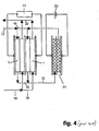
figure 4 : stack of fuel cells offigure 1 with hydrogen internal recirculation obtained according to the prior art by means of the hydrogen-transfer cell offigure 3 installed as a separate element. -
figure 5 : stack of ion-exchange membrane fuel cells offigure 1 with hydrogen external recirculation obtained according to the prior art with the hydrogen-transfer cell offigure 3 mechanically associated with the fuel cell. -
figure 6 : stack comprising two units according to a first embodiment of the invention, with partial lateral section, wherein each unit consists of the fuel cell offigure 1 integrated with the hydrogen-transfer cell offigure 3 by common lamination, with the fuel cell and hydrogen-transfer cell components enclosed between two bipolar plates and with internal recirculation of hydrogen. -
figure 7 : stack comprising two units in accordance with an alternative embodiment of the invention, with partial lateral section, wherein each unit consists of the fuel cell offigure 1 mechanically associated by common lamination with the hydrogen-transfer cell offigure 3 , with the fuel cell and hydrogen-transfer cell components enclosed between two external bipolar plates and kept separate by a further intermediate bipolar plate, with internal hydrogen recirculation. - The unit of the present invention comprises a fuel cell co-laminated and integrated or mechanically associated with a hydrogen-transfer cell giving rise to a novel internal recirculation of hydrogen.
- The lateral section of a fuel cell internal structure is sketched in
figure 1 , wherein (1) identifies the fuel cell in its entirety and wherein (2) indicates the conductive bipolar plates enclosing the internal components, (3) the ion-exchange membrane, (4) and (5) respectively the anode and the cathode, (6) and (7) the current collectors also taking the role of reactant gas distributors, (8) the perimetrical gaskets preventing the reactant gases to escape to the external environment, (9) and (10) the ducts contained, according to a possible embodiment, in the gaskets (8) for the feed/extraction of hydrogen and air respectively, (11) the user load of the output electrical energy. When fed with pure hydrogen supplied in a stoichiometric amount, this type of fuel cell is subject to performance decay as a consequence of a progressive build-up of nitrogen and liquid water which diffuse from the cathodic compartment across the membrane. - A first solution to this problem proposed by the prior art is indicated in
figure 2 : the hydrogen (12) discharged in the manifold (13) by the stack (14) of fuel cells (1), limited to two for simplicity of illustration, is sucked in by the mechanical pump (15) and sent back under a suitable pressure into the distributing manifold (16), and thence to the anode compartments of the fuel cells (1). The hydrogen feed (17) is connected in its turn to the distributing manifold (16). The air feed (18) is sent to the distributing manifold (19) and thence to the cathode compartments of the fuel cells (1), the air discharged from the cathode compartments of the fuel cells (1) is collected in the manifold (20) and thence vented to the external environment. The high hydrogen flow-rate, combined with a little purge not shown in the figure, allows maintaining the nitrogen concentration at low levels and preventing liquid water build-ups on the fuel cell (1) anode compartment. Nevertheless, as a consequence of hydrogen apportionment defects from the distributing manifold (16) to the anode compartments of the individual fuel cells due to the production tolerance of the components and to assemblage irregularities particularly when the stacks (14) comprise a multiplicity of fuel cells, as normally occurs in the practice, the hydrogen flow-rates in some fuel cells may be sensibly reduced with respect to the average project value, to such an extent as to reestablish the phenomena of nitrogen enrichment and especially of liquid water build-up. For simplicity of illustration infigure 2 the fuel cells stack cooling circuits required to maintain the operating temperatures in the approximate range of 60 - 100°C are not shown. The same simplification is applied to the stacks offigures 4 ,5 ,6 and7 . -
Figure 3 represents a sketch of a lateral section of a hydrogen-transfer electrochemical cell as known in the prior art: in particular (21) indicates the cell in its entirety, (2) the two bipolar plates, equivalent to those described for the fuel cell offigure 1 , (6) and (7) two current collectors also functioning as gas distributors, also equivalent to the current collectors described for the fuel cell offigure 1 , (22) an ion-exchange membrane, (23) and (24) respectively the anode and the cathode, (25) and (26) the perimetrical gaskets for sealing the gases toward the external environment respectively provided with feed ducts for the hydrogen to be recycled (27) and with hydrogen discharge ducts (28) under a suitable pressure to be sent to the recycle. During operation, the hydrogen fed through (27) is ionised on the anode (23) with generation of protons which migrate across the membrane (22) to the cathode (24): on the cathode (24), the protons are again converted into hydrogen. The overall flux hydrogen → protons → hydrogen is indicated by the arrows. - The prior art discloses the use of this kind of hydrogen-transfer cell as a replacement for the mechanical pump (15) of
figure 2 according to the two alternatives illustrated infigures 4 and5 , wherein the hydrogen-transfer electrochemical cell (21) is respectively installed as a separate module fed with a suitable external electrical generator (30) or mechanically assembled in a single stack together with the fuel cells (1). Only two fuel cells are shown in this and in other figures of the present application for the sake of simplicity but in principle, any number of fuel cells can be laminated in a stack. In the latter case, the hydrogen-transfer cell is operated making use of part of the electrical output of the fuel cell. The other elements of the circuit are entirely equivalent to those offigure 2 and are therefore identified with the same numerals. - In operation, the ionisation of hydrogen on the anode (23) causes a certain depression which favours the inlet flow to the hydrogen-transfer cell through the duct (27), while the reconversion of protons to hydrogen on the cathode (24) produces a certain pressurisation which directs hydrogen to the manifold (16) and thence to the fuel cell (1) anode compartments. Both kinds of circuit of
figures 4 and5 suffer the same problem seen in the case of the circuit offigure 2 , due as mentioned to the practical difficulty of maintaining an adequate hydrogen flow in each fuel cell of the multiplicity normally making up a stack. - The present invention is directed to solve the problem of nitrogen and liquid water build-up on the anode compartment of membrane fuel cells fed with pure hydrogen overcoming the drawbacks of the prior art.
- A first embodiment of the invention is represented in
figure 6 , which sketches a side-view of a stack comprising, only for the sake of graphic simplification, two units each consisting of a fuel cell (1) of the type offigure 1 co-laminated and integrated with a hydrogen-transfer cell (21) offigure 3 . - The side-view of the stack is partially represented in section and shows the integration in accordance with the invention between the components of a hydrogen-transfer cell (21) and an adjacent fuel cell (1): in particular, the cathodic current collector of the hydrogen-transfer cell also constitutes the fuel cell anodic current collector and hence the hydrogen-transfer cell (21) cathode compartment acts as the fuel cell (1) anode compartment. As a consequence, the gap comprised between two consecutive bipolar plates results subdivided into three portions, respectively, proceeding from left to right: hydrogen-transfer cell anode compartment; hydrogen-transfer cell cathode compartment coinciding with the fuel cell anode compartment; and fuel cell cathode compartment. During operation, the pure hydrogen feed (17) is introduced into the distributing manifold (16) and thence in the fuel cell (1) anode compartment. The hydrogen (12) discharged from the fuel cells into the manifold (13) is sucked in by the hydrogen-transfer cells and ionised to protons on the anode (23). Protons migrate across the membrane (22) and are reconverted to hydrogen at the cathode (24). The hydrogen formed at the cathode (24) is not sent to the external distributing manifold (16), as was the case of the prior art, but is instead mixed to the hydrogen feed coming from the distributing manifold (16) directly inside the fuel cell: in this way a safe hydrogen recirculation is achieved depending only on the electric current crossing the stack, by no means affected by possible problems of distribution of the gas flow associated with production tolerances or assembly inaccuracies. The internal recycle flux: hydrogen on the hydrogen-transfer cell anode compartment → protons → hydrogen on the fuel cell anode compartment is indicated by the arrows. A second embodiment of the invention is represented in
figure 7 , which sketches a side-view of a stack comprising two units, each consisting of a fuel cell (1) of the type offigure 1 mechanically associated by common lamination with a hydrogen-transfer electrochemical cell (21) offigure 3 . The partial section of the side-view shows that the hydrogen-transfer cell (21) and the adjacent fuel cell (1), comprised between two external bipolar plates, maintain their identity being kept separate by a further intermediate bipolar plate. In this case the integration between the hydrogen-transfer cell and the fuel cell is of functional type: the hydrogen produced at the cathode (24) of the hydrogen-transfer cell is in fact injected into the fuel cell anode compartment through a series of aligned holes, indicated as (29), on the intermediate bipolar plate in particular, the recycled hydrogen is not sent to the external distributing manifold (16) as occurs in the prior art. Hence, also with the latter constructive solution, an internal hydrogen recycle not affected by possible problems of bad distribution associated the with production tolerance of the various components and with assembly inaccuracies is obtained. A similar result might be obtained with an alternative internal design based on appropriate ducts, not shown in the figure, obtained inside the gaskets (26) and (8) coupled to corresponding holes made on the intermediate bipolar plate. The flux: hydrogen → protons → hydrogen on the hydrogen-transfer cell anode compartment → holes on the intermediate bipolar plate → hydrogen on the fuel cell anode compartment is indicated by the arrows. The stack according to the invention consisting of fuel cells co-laminated and integrated or mechanically associated with hydrogen-transfer electrochemical cells is certainly characterised by higher volume and weight than those typical of the stack only comprising fuel cells, and at first sight it may seem penalised in automotive applications wherein volumes and weights must be evidently minimised. However the stack of the invention is provided with hydrogen internal recycle, therefore allowing to get rid of the external mechanical pump with the relevant connections and flow-rate regulations, so that the effective overall bulks and weights are not substantially changed. Furthermore the operative reliability of the stack of the invention is certainly higher since the stack is practically a solid-state device consisting of fixed parts only, and therefore free of the rotating parts of the mechanical recirculation pump. The stack of the invention finally allows particularly simplified regulations: as in fact the hydrogen-transfer cells are connected to the fuel cells in electrical series, the stack current output to the electrical user loads also determines the hydrogen recycle flow-rate. Moreover, since the output current also determines the hydrogen feed flow-rate, the ratio between the two feed and recycle flow-rates is always constant and equal to 1. Conversely, in the case of the conventional systems comprising the external recycle mechanical pump, it is necessary to send a signal proportional to the output current to a control device which consequently provides for the regulation of the rotating speed of the electric engine associated with the pump. A further objection which could be raised against the stack of the invention regards the required investment, particularly as concerns the anode - membrane - cathode assemblies of the hydrogen-transfer electrochemical cells which are in the same amount as the equivalent fuel cell assemblies. The latter are in fact rather expensive components as they have to make use of perfluorinated membranes, the only one known for the time being which ensure an adequate chemical inertia toward the aggressive radical intermediates formed on the cathode by the reduction of the oxygen of air. Moreover, the oxygen reaction rate becomes acceptable only with relevant amounts of platinum-based catalysts. Nevertheless, the assemblies incorporated in the hydrogen-transfer cells turn out to be largely cheaper: in this case, in fact, both the anodic and the cathodic reaction involve the presence of hydrogen and not of oxygen with the associated radical intermediates, and as a consequence it is possible to resort to the cheap hydrocarbon-type ion-exchange membranes. Furthermore, since both the hydrogen anodic ionisation to form protons and the proton cathodic reconversion to hydrogen have very fast kinetics, it is possible to use very limited amounts of platinum-based catalysts. The only requirement for the assemblies incorporated in the hydrogen-transfer cells is that their internal impedance should preferably be limited around a value not higher than 100 - 150 milliohm.cm2, so as to absorb modest fractions of electrical energy during operation. - One application of the present invention is disclosed in the following example, which should in no way be intended as a limitation but just as an exemplification for a better comprehension of the obtainable advantages.
- A stack of the type sketched in
figure 6 was assembled with 70 fuel cells intercalated with an equal number of hydrogen-transfer electrochemical cells, with the following characteristic elements: - active area of each fuel cell and of each hydrogen-transfer cell: 500 cm2.
- PRIMEA® type anode - perfluorinated membrane - cathode assemblies for fuel cell, with a total 1 mg/cm2 of Pt, provided by Gore/Japan.
- anode - hydrocarbon-type membrane - cathode experimental assemblies for hydrogen-transfer cell with a total 0.2 mg/cm2 of Pt.
- AISI 316L-type stainless steel bipolar plates.
- current collectors of nickel-chromium metal foam.
- punched gaskets of ABS polymer.
- air feed with twice the theoretical flow-rate required for each level of current output, at a pressure of 1.3 bar abs.
- self-regulated hydrogen feed as a function of the current output and the purges, at a pressure of 1.8 bar abs.
- hydrogen purging every 20 minutes, approximately corresponding to 2% of the total feed.
- stack cooling with cooling water at constant flow-rate and with inlet and outlet temperature of respectively 51 and 53°C.
- output current: 100 A.
- overall stack voltage: 47 V, constant during a test duration of 1200 hours.
- average voltage of a single fuel cell: 0.7 V.
- average voltage of a single hydrogen-transfer cell: 0.03 V.
- The above listed data show that it is possible to obtain a stable operation in time of a big stack thanks to the hydrogen internal recycle achieved according to the first embodiment of the invention, The data also show that the electric power absorbed by the hydrogen-transfer cells to ensure the hydrogen internal recycle in all of the fuel cells is equal to 210 W (0.03 x 70 x 100) corresponding to about 5% of the 4900 W power (0.7 x 70 x 100) that the fuel cells can generate.
Claims (14)
- Unit comprising a membrane fuel cell (1) fed with hydrogen at the anodic compartment and with air at the cathodic compartment connected in electrical series to a hydrogen-transfer electrochemical cell (21) subdivided by an ion-exchange membrane into one anodic compartment and one cathodic compartment, wherein said fuel cell and said hydrogen-transfer cell are co-laminated in an integrated structure and said anodic compartment of said hydrogen-transfer cell is fed with the anodic exhaust of said fuel cell, and the hydrogen evolved at the cathodic compartment of said transfer cell is internally recycled within said integrated structure as a fraction of the anode feed of said fuel cell.
- The unit of claim 1 wherein said fuel cell and said hydrogen-transfer cell are co-laminated in an integrated structure delimited by two external bipolar plates.
- The unit of claim 2 wherein said anodic compartment of said fuel cell coincides with said cathodic compartment of said hydrogen-transfer cell.
- The unit of claim 3 wherein said anodic compartment of said fuel cell coinciding with said cathodic compartment of said hydrogen-transfer cell contains a reticulated metal current collector.
- The unit of claim 1 wherein said fuel cell and said hydrogen-transfer cell are co-laminated in an integrated structure delimited by two external bipolar plates and comprising an intermediate bipolar plate separating said fuel cell from said hydrogen-transfer cell.
- The unit of claim 5 wherein said intermediate bipolar plate is provided with holes permitting the internal recycle of said anodic exhaust of said fuel cell to said anodic compartment of said transfer cell.
- The unit of claim 6 wherein said fuel cell and said hydrogen-transfer cell comprise perimetrical gaskets provided with holes aligned to said holes of said intermediate bipolar plate forming by juxtaposition a duct permitting the internal recycle of said anodic exhaust of said fuel cell to said anodic compartment of said transfer cell.
- The unit of the preceding claims wherein said fuel cell is provided with a connection for the discharge of the anodic exhaust connected to the anode feed of said hydrogen-transfer cell and to a purging device.
- The unit of the preceding claims wherein said ion-exchange membrane subdividing said hydrogen-transfer cell into one anodic compartment and one cathodic compartment is a hydrocarbon membrane.
- The unit of the preceding claims wherein said ion-exchange membrane subdividing said hydrogen-transfer cell into one anodic compartment and one cathodic compartment comprises an anode and a cathode with an overall content of noble metal not exceeding 0.5 mg/cm2.
- Direct electric current generator comprising a multiplicity of units of the preceding claims in electrical series.
- The generator of claim 11 comprising a common manifold for feeding hydrogen to said fuel cells of said units.
- The generator of claim 11 or 12 comprising a common manifold for the discharge of said anodic exhaust from said fuel cells connected to the anode feed of said hydrogen-transfer cells.
- Method of production of electrical energy through the generator of any one of claims from 11 to 13 wherein said fraction of hydrogen anode feed produced in said transfer cells and recycled to said fuel cells equals half of the overall anode feed of said fuel cells independently on the output current.
Applications Claiming Priority (2)
| Application Number | Priority Date | Filing Date | Title |
|---|---|---|---|
| IT002351A ITMI20042351A1 (en) | 2004-12-10 | 2004-12-10 | FUEL CELL WITH INTERNAL HYDROGEN RECIRCULATION |
| PCT/EP2005/013235 WO2006061239A1 (en) | 2004-12-10 | 2005-12-09 | Fuel cell with hydrogen internal recirculation |
Publications (2)
| Publication Number | Publication Date |
|---|---|
| EP1825551A1 EP1825551A1 (en) | 2007-08-29 |
| EP1825551B1 true EP1825551B1 (en) | 2009-06-03 |
Family
ID=36084798
Family Applications (1)
| Application Number | Title | Priority Date | Filing Date |
|---|---|---|---|
| EP05850248A Expired - Lifetime EP1825551B1 (en) | 2004-12-10 | 2005-12-09 | Fuel cell with hydrogen internal recirculation |
Country Status (8)
| Country | Link |
|---|---|
| US (1) | US7887961B2 (en) |
| EP (1) | EP1825551B1 (en) |
| JP (1) | JP2008523550A (en) |
| AT (1) | ATE433204T1 (en) |
| CA (1) | CA2588171A1 (en) |
| DE (1) | DE602005014807D1 (en) |
| IT (1) | ITMI20042351A1 (en) |
| WO (1) | WO2006061239A1 (en) |
Families Citing this family (6)
| Publication number | Priority date | Publication date | Assignee | Title |
|---|---|---|---|---|
| DE102007027005B4 (en) | 2007-06-06 | 2011-07-28 | Deutsches Zentrum für Luft- und Raumfahrt e.V., 51147 | Electrochemical device and method for operating an electrochemical device |
| JP5912878B2 (en) * | 2012-05-31 | 2016-04-27 | 株式会社神鋼環境ソリューション | Hydrogen oxygen generator and operation method of hydrogen oxygen generator |
| JP2014049357A (en) * | 2012-08-31 | 2014-03-17 | Shih-Hang Chou | Hydrogen fuel cell |
| US20160380275A1 (en) * | 2014-12-11 | 2016-12-29 | Hamilton Sundstrand Space Systems International, Inc. | Multi-voltage fuel cell |
| DE102019217210A1 (en) * | 2019-11-07 | 2021-05-12 | Robert Bosch Gmbh | Cell arrangement |
| CN113764706B (en) * | 2020-12-31 | 2023-03-21 | 厦门大学 | Secondary fuel cell with active circulation system |
Family Cites Families (10)
| Publication number | Priority date | Publication date | Assignee | Title |
|---|---|---|---|---|
| JP2777299B2 (en) * | 1991-12-16 | 1998-07-16 | 三菱電機株式会社 | Hydrogen-water recovery mechanism for fuel cell stack |
| JPH10321248A (en) * | 1997-05-22 | 1998-12-04 | Matsushita Electric Works Ltd | /fuel cell-based electric power generation system |
| JP2000030730A (en) * | 1998-07-08 | 2000-01-28 | Toyota Motor Corp | Fuel cell |
| JP3644667B2 (en) * | 1999-07-06 | 2005-05-11 | 三菱電機株式会社 | Fuel cell power generator |
| JP4232137B2 (en) * | 2001-05-08 | 2009-03-04 | スズキ株式会社 | Fuel cell |
| JP2003059494A (en) * | 2001-08-09 | 2003-02-28 | Asahi Glass Co Ltd | Operation method and fuel cell apparatus of polymer electrolyte fuel cell |
| JP3939640B2 (en) * | 2002-12-24 | 2007-07-04 | 本田技研工業株式会社 | Reactive gas circulation fuel cell system |
| US6994929B2 (en) * | 2003-01-22 | 2006-02-07 | Proton Energy Systems, Inc. | Electrochemical hydrogen compressor for electrochemical cell system and method for controlling |
| US7449260B2 (en) * | 2003-12-23 | 2008-11-11 | Utc Power Corporation | Fuel cell stack including hydrogen pumping fuel cells |
| JP2005268056A (en) * | 2004-03-18 | 2005-09-29 | Central Japan Railway Co | Hydrogen supply system and fuel cell system |
-
2004
- 2004-12-10 IT IT002351A patent/ITMI20042351A1/en unknown
-
2005
- 2005-12-09 WO PCT/EP2005/013235 patent/WO2006061239A1/en not_active Ceased
- 2005-12-09 JP JP2007544831A patent/JP2008523550A/en active Pending
- 2005-12-09 AT AT05850248T patent/ATE433204T1/en not_active IP Right Cessation
- 2005-12-09 DE DE602005014807T patent/DE602005014807D1/en not_active Expired - Lifetime
- 2005-12-09 EP EP05850248A patent/EP1825551B1/en not_active Expired - Lifetime
- 2005-12-09 US US11/667,157 patent/US7887961B2/en active Active
- 2005-12-09 CA CA002588171A patent/CA2588171A1/en not_active Abandoned
Also Published As
| Publication number | Publication date |
|---|---|
| CA2588171A1 (en) | 2006-06-15 |
| JP2008523550A (en) | 2008-07-03 |
| DE602005014807D1 (en) | 2009-07-16 |
| US7887961B2 (en) | 2011-02-15 |
| EP1825551A1 (en) | 2007-08-29 |
| WO2006061239A1 (en) | 2006-06-15 |
| ATE433204T1 (en) | 2009-06-15 |
| ITMI20042351A1 (en) | 2005-03-10 |
| US20080124589A1 (en) | 2008-05-29 |
Similar Documents
| Publication | Publication Date | Title |
|---|---|---|
| US6727012B2 (en) | Method and apparatus for generating hydrogen inside of a fuel cell | |
| AU2002219941B2 (en) | Multipurpose reversible electrochemical system | |
| US7241521B2 (en) | Hydrogen/hydrogen peroxide fuel cell | |
| JP6263638B2 (en) | Assembly method and arrangement for cell system | |
| US8206864B2 (en) | Fuel cell stacks and systems with fluid-responsive temperature regulation | |
| US20090068512A1 (en) | Hydrogen refueling station | |
| US20080292921A1 (en) | Recovery of inert gas from a fuel cell exhaust stream | |
| EP1986264A1 (en) | System for generating electrical energy comprising an electrochemical reformer and a fuel cell | |
| US6896792B2 (en) | Method and device for improved catalytic activity in the purification of fluids | |
| EP0721674A1 (en) | Electrochemical fuel cell assembly with integral selective oxidizer | |
| JPH06203863A (en) | Fuel cell equipment and method for controlling inert gas emission thereof | |
| US7887961B2 (en) | Fuel cell with hydrogen internal recirculation | |
| US6821664B2 (en) | Method and apparatus for a combined fuel cell and hydrogen purification system | |
| KR100757440B1 (en) | Purge device of fuel cell | |
| EP3394922B1 (en) | Process and an apparatus for the production of compressed hydrogen | |
| US7479335B2 (en) | Anode humidification | |
| US20040038103A1 (en) | Solid polymer electrolyte fuel cell assembly | |
| KR20090036014A (en) | Stack Purification Method of Fuel Cell System | |
| US20040067397A1 (en) | Architected fuel cell system for modular application | |
| JP2020017338A (en) | Fuel cell system and power generation method | |
| US20080023322A1 (en) | Fuel processor | |
| JP2007335145A (en) | Fuel cell system | |
| Mustafa et al. | Conceptual Reduced Cost PEM Fuel Cell Design for Domestic Applications | |
| JPH0467575A (en) | Fuel cell | |
| JP2007335112A (en) | Fuel cell |
Legal Events
| Date | Code | Title | Description |
|---|---|---|---|
| PUAI | Public reference made under article 153(3) epc to a published international application that has entered the european phase |
Free format text: ORIGINAL CODE: 0009012 |
|
| 17P | Request for examination filed |
Effective date: 20070522 |
|
| AK | Designated contracting states |
Kind code of ref document: A1 Designated state(s): AT BE BG CH CY CZ DE DK EE ES FI FR GB GR HU IE IS IT LI LT LU LV MC NL PL PT RO SE SI SK TR |
|
| DAX | Request for extension of the european patent (deleted) | ||
| GRAP | Despatch of communication of intention to grant a patent |
Free format text: ORIGINAL CODE: EPIDOSNIGR1 |
|
| GRAS | Grant fee paid |
Free format text: ORIGINAL CODE: EPIDOSNIGR3 |
|
| GRAA | (expected) grant |
Free format text: ORIGINAL CODE: 0009210 |
|
| AK | Designated contracting states |
Kind code of ref document: B1 Designated state(s): AT BE BG CH CY CZ DE DK EE ES FI FR GB GR HU IE IS IT LI LT LU LV MC NL PL PT RO SE SI SK TR |
|
| REG | Reference to a national code |
Ref country code: GB Ref legal event code: FG4D |
|
| REG | Reference to a national code |
Ref country code: CH Ref legal event code: EP |
|
| REG | Reference to a national code |
Ref country code: IE Ref legal event code: FG4D |
|
| REF | Corresponds to: |
Ref document number: 602005014807 Country of ref document: DE Date of ref document: 20090716 Kind code of ref document: P |
|
| PG25 | Lapsed in a contracting state [announced via postgrant information from national office to epo] |
Ref country code: FI Free format text: LAPSE BECAUSE OF FAILURE TO SUBMIT A TRANSLATION OF THE DESCRIPTION OR TO PAY THE FEE WITHIN THE PRESCRIBED TIME-LIMIT Effective date: 20090603 Ref country code: LT Free format text: LAPSE BECAUSE OF FAILURE TO SUBMIT A TRANSLATION OF THE DESCRIPTION OR TO PAY THE FEE WITHIN THE PRESCRIBED TIME-LIMIT Effective date: 20090603 Ref country code: AT Free format text: LAPSE BECAUSE OF FAILURE TO SUBMIT A TRANSLATION OF THE DESCRIPTION OR TO PAY THE FEE WITHIN THE PRESCRIBED TIME-LIMIT Effective date: 20090603 |
|
| NLV1 | Nl: lapsed or annulled due to failure to fulfill the requirements of art. 29p and 29m of the patents act | ||
| PG25 | Lapsed in a contracting state [announced via postgrant information from national office to epo] |
Ref country code: LV Free format text: LAPSE BECAUSE OF FAILURE TO SUBMIT A TRANSLATION OF THE DESCRIPTION OR TO PAY THE FEE WITHIN THE PRESCRIBED TIME-LIMIT Effective date: 20090603 Ref country code: SI Free format text: LAPSE BECAUSE OF FAILURE TO SUBMIT A TRANSLATION OF THE DESCRIPTION OR TO PAY THE FEE WITHIN THE PRESCRIBED TIME-LIMIT Effective date: 20090603 Ref country code: PL Free format text: LAPSE BECAUSE OF FAILURE TO SUBMIT A TRANSLATION OF THE DESCRIPTION OR TO PAY THE FEE WITHIN THE PRESCRIBED TIME-LIMIT Effective date: 20090603 Ref country code: NL Free format text: LAPSE BECAUSE OF FAILURE TO SUBMIT A TRANSLATION OF THE DESCRIPTION OR TO PAY THE FEE WITHIN THE PRESCRIBED TIME-LIMIT Effective date: 20090603 Ref country code: SE Free format text: LAPSE BECAUSE OF FAILURE TO SUBMIT A TRANSLATION OF THE DESCRIPTION OR TO PAY THE FEE WITHIN THE PRESCRIBED TIME-LIMIT Effective date: 20090903 |
|
| PG25 | Lapsed in a contracting state [announced via postgrant information from national office to epo] |
Ref country code: ES Free format text: LAPSE BECAUSE OF FAILURE TO SUBMIT A TRANSLATION OF THE DESCRIPTION OR TO PAY THE FEE WITHIN THE PRESCRIBED TIME-LIMIT Effective date: 20090914 Ref country code: RO Free format text: LAPSE BECAUSE OF FAILURE TO SUBMIT A TRANSLATION OF THE DESCRIPTION OR TO PAY THE FEE WITHIN THE PRESCRIBED TIME-LIMIT Effective date: 20090603 Ref country code: EE Free format text: LAPSE BECAUSE OF FAILURE TO SUBMIT A TRANSLATION OF THE DESCRIPTION OR TO PAY THE FEE WITHIN THE PRESCRIBED TIME-LIMIT Effective date: 20090603 Ref country code: CZ Free format text: LAPSE BECAUSE OF FAILURE TO SUBMIT A TRANSLATION OF THE DESCRIPTION OR TO PAY THE FEE WITHIN THE PRESCRIBED TIME-LIMIT Effective date: 20090603 Ref country code: IS Free format text: LAPSE BECAUSE OF FAILURE TO SUBMIT A TRANSLATION OF THE DESCRIPTION OR TO PAY THE FEE WITHIN THE PRESCRIBED TIME-LIMIT Effective date: 20091003 |
|
| PG25 | Lapsed in a contracting state [announced via postgrant information from national office to epo] |
Ref country code: BE Free format text: LAPSE BECAUSE OF FAILURE TO SUBMIT A TRANSLATION OF THE DESCRIPTION OR TO PAY THE FEE WITHIN THE PRESCRIBED TIME-LIMIT Effective date: 20090603 Ref country code: SK Free format text: LAPSE BECAUSE OF FAILURE TO SUBMIT A TRANSLATION OF THE DESCRIPTION OR TO PAY THE FEE WITHIN THE PRESCRIBED TIME-LIMIT Effective date: 20090603 |
|
| PG25 | Lapsed in a contracting state [announced via postgrant information from national office to epo] |
Ref country code: BG Free format text: LAPSE BECAUSE OF FAILURE TO SUBMIT A TRANSLATION OF THE DESCRIPTION OR TO PAY THE FEE WITHIN THE PRESCRIBED TIME-LIMIT Effective date: 20090903 Ref country code: PT Free format text: LAPSE BECAUSE OF FAILURE TO SUBMIT A TRANSLATION OF THE DESCRIPTION OR TO PAY THE FEE WITHIN THE PRESCRIBED TIME-LIMIT Effective date: 20091003 |
|
| PLBE | No opposition filed within time limit |
Free format text: ORIGINAL CODE: 0009261 |
|
| STAA | Information on the status of an ep patent application or granted ep patent |
Free format text: STATUS: NO OPPOSITION FILED WITHIN TIME LIMIT |
|
| PG25 | Lapsed in a contracting state [announced via postgrant information from national office to epo] |
Ref country code: DK Free format text: LAPSE BECAUSE OF FAILURE TO SUBMIT A TRANSLATION OF THE DESCRIPTION OR TO PAY THE FEE WITHIN THE PRESCRIBED TIME-LIMIT Effective date: 20090603 |
|
| 26N | No opposition filed |
Effective date: 20100304 |
|
| PG25 | Lapsed in a contracting state [announced via postgrant information from national office to epo] |
Ref country code: MC Free format text: LAPSE BECAUSE OF NON-PAYMENT OF DUE FEES Effective date: 20100701 |
|
| REG | Reference to a national code |
Ref country code: CH Ref legal event code: PL |
|
| GBPC | Gb: european patent ceased through non-payment of renewal fee |
Effective date: 20091209 |
|
| REG | Reference to a national code |
Ref country code: IE Ref legal event code: MM4A |
|
| PG25 | Lapsed in a contracting state [announced via postgrant information from national office to epo] |
Ref country code: CH Free format text: LAPSE BECAUSE OF NON-PAYMENT OF DUE FEES Effective date: 20091231 Ref country code: IE Free format text: LAPSE BECAUSE OF NON-PAYMENT OF DUE FEES Effective date: 20091209 Ref country code: LI Free format text: LAPSE BECAUSE OF NON-PAYMENT OF DUE FEES Effective date: 20091231 Ref country code: GR Free format text: LAPSE BECAUSE OF FAILURE TO SUBMIT A TRANSLATION OF THE DESCRIPTION OR TO PAY THE FEE WITHIN THE PRESCRIBED TIME-LIMIT Effective date: 20090904 |
|
| PG25 | Lapsed in a contracting state [announced via postgrant information from national office to epo] |
Ref country code: GB Free format text: LAPSE BECAUSE OF NON-PAYMENT OF DUE FEES Effective date: 20091209 |
|
| PG25 | Lapsed in a contracting state [announced via postgrant information from national office to epo] |
Ref country code: IT Free format text: LAPSE BECAUSE OF FAILURE TO SUBMIT A TRANSLATION OF THE DESCRIPTION OR TO PAY THE FEE WITHIN THE PRESCRIBED TIME-LIMIT Effective date: 20090603 |
|
| PG25 | Lapsed in a contracting state [announced via postgrant information from national office to epo] |
Ref country code: LU Free format text: LAPSE BECAUSE OF NON-PAYMENT OF DUE FEES Effective date: 20091209 |
|
| PG25 | Lapsed in a contracting state [announced via postgrant information from national office to epo] |
Ref country code: HU Free format text: LAPSE BECAUSE OF FAILURE TO SUBMIT A TRANSLATION OF THE DESCRIPTION OR TO PAY THE FEE WITHIN THE PRESCRIBED TIME-LIMIT Effective date: 20091204 |
|
| PG25 | Lapsed in a contracting state [announced via postgrant information from national office to epo] |
Ref country code: TR Free format text: LAPSE BECAUSE OF FAILURE TO SUBMIT A TRANSLATION OF THE DESCRIPTION OR TO PAY THE FEE WITHIN THE PRESCRIBED TIME-LIMIT Effective date: 20090603 |
|
| PG25 | Lapsed in a contracting state [announced via postgrant information from national office to epo] |
Ref country code: CY Free format text: LAPSE BECAUSE OF FAILURE TO SUBMIT A TRANSLATION OF THE DESCRIPTION OR TO PAY THE FEE WITHIN THE PRESCRIBED TIME-LIMIT Effective date: 20090603 |
|
| PGFP | Annual fee paid to national office [announced via postgrant information from national office to epo] |
Ref country code: DE Payment date: 20141211 Year of fee payment: 10 |
|
| REG | Reference to a national code |
Ref country code: FR Ref legal event code: PLFP Year of fee payment: 11 |
|
| REG | Reference to a national code |
Ref country code: DE Ref legal event code: R119 Ref document number: 602005014807 Country of ref document: DE |
|
| PG25 | Lapsed in a contracting state [announced via postgrant information from national office to epo] |
Ref country code: DE Free format text: LAPSE BECAUSE OF NON-PAYMENT OF DUE FEES Effective date: 20160701 |
|
| REG | Reference to a national code |
Ref country code: FR Ref legal event code: PLFP Year of fee payment: 12 |
|
| REG | Reference to a national code |
Ref country code: FR Ref legal event code: PLFP Year of fee payment: 13 |
|
| PGFP | Annual fee paid to national office [announced via postgrant information from national office to epo] |
Ref country code: FR Payment date: 20241115 Year of fee payment: 20 |