EP1824738B1 - Welding tool for a strapping apparatus - Google Patents
Welding tool for a strapping apparatus Download PDFInfo
- Publication number
- EP1824738B1 EP1824738B1 EP05796290A EP05796290A EP1824738B1 EP 1824738 B1 EP1824738 B1 EP 1824738B1 EP 05796290 A EP05796290 A EP 05796290A EP 05796290 A EP05796290 A EP 05796290A EP 1824738 B1 EP1824738 B1 EP 1824738B1
- Authority
- EP
- European Patent Office
- Prior art keywords
- friction welding
- welding tool
- drive element
- motion
- rotation
- Prior art date
- Legal status (The legal status is an assumption and is not a legal conclusion. Google has not performed a legal analysis and makes no representation as to the accuracy of the status listed.)
- Expired - Lifetime
Links
Images


Classifications
-
- B—PERFORMING OPERATIONS; TRANSPORTING
- B65—CONVEYING; PACKING; STORING; HANDLING THIN OR FILAMENTARY MATERIAL
- B65B—MACHINES, APPARATUS OR DEVICES FOR, OR METHODS OF, PACKAGING ARTICLES OR MATERIALS; UNPACKING
- B65B13/00—Bundling articles
- B65B13/18—Details of, or auxiliary devices used in, bundling machines or bundling tools
- B65B13/24—Securing ends of binding material
- B65B13/32—Securing ends of binding material by welding, soldering, or heat-sealing; by applying adhesive
- B65B13/322—Friction welding
Definitions
- the present invention relates to a friction welding tool used in conjunction with a strapping machine, said welding tool being fitted with a drive of which the output motion can be converted by a mechanism into an oscillating motion of a welding shoe. Moreover the present invention relates to a strapping apparatus fitted with a friction welding tool.
- Such friction welding tools are widely used in conjunction with mobile strapping apparatus that are used at arbitrary stations to strap items to be packed with a superficially fusing strap. In principle however such friction welding tools also may be used with stationary strapping apparatus.
- such strapping apparatus comprises a tensioner applying sufficient tension to the strap loop placed around the particular item to be packed. Thereupon the strap loop may be affixed by a clamping unit of the strapping apparatus to the item to be packed to prepare it for the ensuing lacing procedure.
- the lacing procedure can be implemented using a friction welding tool.
- the strap is depressed by an oscillating friction shoe in the zone between the two ends of the strap loop, This pressure and the heat generated locally and for a short time by the motion superficially fuse the strap, which typically is made of plastic.
- a connection between the two superposed plies of strap is formed which is practically permanent and may be undone at best only applying a large force.
- a plurality of such friction welding tools uses a cam or a connecting rod drive to convert a rotary driving motion into the oscillating motion of the welding shoe. It has been found however that the friction welds so made are not wholly satisfactory. In order to attain optimally welded links, a given amount of heat must be applied within a given time window into a locally bounded segment of the two mutually overlapping strap plies. As regards conventional plastic straps, strap temperatures of about 250 °C are required.
- This feature entails given operational rates of the friction welding shoes while simultaneously given frictions must be applied to the strap, where both the said rates and the friction forces may depend on the nature of the strap. Furthermore the operational rate should be as constant as possible.
- operational rates should be as constant as possible.
- manually operated friction welding tools are used - of which the weight should be as low as possible - to enjoy good handling of the strapping apparatus. Consequently very long drive levers used to apply large torques, or gear units with many transmission stages, are usually not used because of handling difficulties.
- this problem is solved by the invention by means of an approximately polygonal drive element which is configured as seen in the direction of drive transmission between the drive and the welding shoe and which comprises a peripheral surface having at least three zones that are at a larger distance from the axis of rotation than other peripheral zones.
- the approximately polygonal drive element of the present invention allows multiplying the stroke that would otherwise be available from the linkrod design, provided that the approximately polygonal drive element shall comprise at least three peripheral zones that are a larger distance from said unit's axis of rotation. Every two zones of increased distance may enclose a peripheral zone of which the maximum distance to the axis of rotation is less than the least distance from the peripheral surface in one of the adjoining zones.
- This geometry may be used to attain more advantageous welding parameters than heretofore.
- the invention allows significant improvement in the welding tool's efficiency even while simultaneously making possible a more economical welding tool design than heretofore.
- the angular speed may be reduced by a factor of three using manual levers in the preferred application, said angular speed being applied to a shaft connected directly or indirectly to the manual lever. Because of the increased number of strokes per rotation of the drive element, it is thus feasible to attain the same welding parameters as heretofore. Such a feature may be exploited as leading to a simpler design of the friction welding tool, making possible in turn a reduction in weight of the strapping apparatus.
- a polygonal or near-polygonal drive element in the preferred application may be construed being a single or multi-element component connected to a rotary shaft and fitted with a peripheral surface deviating from a circular shape.
- An approximately polygonal drive element is further characterized in that the peripheral surface may comprise as seen in the peripheral direction several mutually adjoining zones that differ in their particular distances from their particular maximum distances from the axis of rotation. The distance between the peripheral surface and the axis of rotation also may vary among the particular zones themselves. Also and as regards their topographies, identical zones may be employed. Illustratively the zones of greater distance to the axis of rotation may be at least approximately congruent. The same design also applies to the zones of lesser maximum distance from the axis of rotation.
- the approximately polygonal drive element may comprise a number of zones farther away from the axis of rotation and preferably said number is odd and larger than 3.
- a zone of lesser distance to the axis of rotation of the approximately polygonal drive element may be configured between every two preferably peripherally sequential zones that are farther away.
- the approximately polygonal drive element may be operationally connected with at least one contacting element in order to transmit to this element a motion resulting from the drive element rotation.
- the drive element is configured between two contacting elements and displaces latter to and fro during a stroke in synchronous, translational manner and in the same direction.
- Said contacting elements are designed to rest against the drive element's peripheral surface.
- the contact between the drive element and the two contacting elements shall be as play-free as possible.
- a preferred joint straight path of the contacting elements may preferably intersect the axis of rotation of the approximately polygonal drive element and be perpendicular to it.
- Sliding friction may exist between the drive element and the minimum of one contacting element.
- the mechanical loading of the minimum of one contacting element and of the drive element shall be in the form of rolling friction.
- This feature may be implemented for instance by imparting a degree of freedom to the contacting elements in the form of rotation about their bearing axis in addition to their ability to translate.
- the diameter lines of the approximately polygonal drive element intersecting the axis of rotation at least approximately shall be of the same length.
- the drive element may be a structure of the same thickness or similar.
- the exclusively manually operated strapping apparatus 1 of the invention shown in Fig. 1 comprises a base plate 2 of which the lower side is designed to be configured on an item to be packed. All operating units of the strapping apparatus 1 are mounted on the base plate 2.
- the various designs of the individual operational units of such strapping apparatus are known in their many ways in the state of the art. Accordingly, following a short discussion of the basic design of said apparatus, the next discussion shall relate only to the welding tool.
- a loop not shown in further detail in Fig. 1 of a plastic strap (for instance made of polypropylene [PP] or of polyethylene terephthalate [PET], previously deposited on the item to be packed, may be tensioned by said apparatus' tensioner 3.
- the tensioner comprises a drum 4 holding the strap to be tensioned. In this manner the loop may be sufficiently tensioned for good strapping.
- the strap loop shall be affixed by a clamp 5 of the strapping apparatus to this apparatus.
- the clamp comprises two strap jaws 6, 7.
- welding may be carried out, at a site of said loop where two strap plies are superposed, by means of the strapping apparatus' friction welding tool 8.
- the friction welding tool 8 is fitted with a welding shoe 9 which, by applying pressure to the strap and by carrying out a simultaneously oscillation motion, does superficially melt the two superposed strap plies onto each other.
- the plasticized or superficially molten segments flow into each other so that, following strap cooling, a connection has been established between the two strap plies.
- the strap loop may severed from a strap roll by a cutter 10 of the strapping apparatus 1.
- the tensioner 3, the clamp 5, the friction welding tool 8 and the cutter 10 are actuated by manually powered actuation elements of the strapping apparatus.
- the strapping apparatus of Fig. 1 does not receive external, additional power such as electricity for instance. However such might be the case for other strapping apparatus of the invention (omitted).
- the said actuation elements include at least one manual lever 15 rotatable about a pivot axis 14 that, by means of omitted connections and/or freewheeling elements, can act on the various operational units.
- the manual lever 15 may be actuated several times to move the welding shoe 9 until welding is complete.
- the pivoting motion of the manual lever 9 in this process is transmitted in a manner not shown in detail to a planetary gear 16 ( Fig. 3 ).
- the planetary gear 16 converts the motion of the shaft of the manual lever 15.
- the drive motion so converted then will rotate a planetary gear output shaft 18.
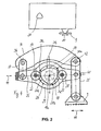
- An approximately polygonal drive element 20 is shown in Fig. 2 , of which the rotational motion is transmitted by a further mechanism 21 to the welding shoe, is mounted on said output shaft.
- This mechanism 21 is shown in highly schematic manner in Fig. 2 by a rectangle and it may in principle be designed in very many ways.
- the approximately polygonal drive element 20 is situated between two contact elements designed as radially cylindrical roller bearings 22, 23 (hereafter roller bearings).
- the two roller bearings 22, 23 rest at a mutual offset of about 180° against a peripheral surface 24 of the approximately polygonal drive element 20.
- Said roller bearings are configured in a manner that their axes of rotations run parallel to the axis of rotation 18a of the approximately polygonal drive element. All three axes of rotation intersect a straight displacement path 25 along which the roller bearings 22, 23 may translate.
- the roller bearings 22, 23 are mounted respectively by their inner rings on bolts 27, 28, the two bolts resting in a fork-shaped guide bracket 29. Both the roller bearings 22, 23 and the drive element 20 are situated within the fork subtended by the guide bracket.
- the translations of the roller bearings 22, 23 are determined by a given geometry of the peripheral surface 24 of the approximately polygonal drive element 20, namely said drive element comprises three zones 30a, 30b, 30c at its peripheral surface that are farther away from its axis of rotation. These three zones are apart by 120° from each other.
- a zone 31a, 31b, 31c of the peripheral surface 24 is situated in each case between two of those zones 30a, 30b, 30c at comparatively smaller radial distances from the drive element's axis of rotation 18a.
- the zones 31 a, 31b, 31c situated at lesser radial distances also are equidistant by about 120°.
- the contact sites between a particular roller bearing and the drive element may shift in relation to the translational path and they may be situated on the displacement path 25 as well as above or below. In this manner tangential contact may be attained at the particular contact site, that is a contact site at which a common tangent exists for both contacting partners. This constraint should affect the shaping of the individual zones of the approximately polygonal drive element.
- the fork-shaped guide bracket 29 is linked at its left end, as seen in Fig. 3 , by means of a rotatably supported connecting lever 33 to an upper lever 34.
- a welding shoe lever 35 is linked to the right end of the guide bracket 29 and also by its upper end to the upper lever 35.
- the upper lever 34 rests on the base plate 2 at the linkage site 36 of the connecting lever 33 in a manner not shown in further detail in Fig. 3 .
- the welding shoe 9 is linked in tipping manner to the lower end of the welding shoe lever 35.
- the guide bracket 29, the connection lever 33, the upper lever 34 and the welding shoe lever 34 constitute a parallelogram.
- An omitted tension spring affixed both to the upper lever 34 and in the region of the base plate 2 forces the upper lever 34 and hence the welding shoe 9 toward the base plate 2.
- the distance from the linkage site 41 of the guide bracket 29 at the welding shoe lever 35 to the linkage site art the upper lever shall be 1/2 or less than the distance between the linkage site 41 of the guide bracket 29 and the linkage site 43 of the welding shoe 9. In this manner the linkage site 41 of the guide bracket 29 divides the welding shoe lever 35 into segments which are 1/3 to 2/3 the lever's length.
- the two roller bearings 22, 23 both resting in the fork-like guide bracket 29 synchronously and jointly carry out three complete double strokes (along the double arrow 44) of identical lengths along the translation displacement path 25 for one revolution of the drive element 20.
- the translations of the roller bearings 22, 23 are transmitted by their support bolts 27, 28 to the guide bracket 29.
- the site 41 linking the welding shoe lever 35 to the guide bracket 29 then entails a swivel motion of the welding shoe lever 35 of which the motion furthermore is furthermore determined by the linkage of the welding shoe lever 35 at the upper lever 34.
- the motion of the upper lever 34 is determined by the linkage of the guide bracket 29 via the connection lever 33 to the upper lever 34 and also by the tipping support of the upper lever about the axis of the linkage site 36.
- the motion of said lever 34 is affected by the force exerted on it by the omitted tension spring.
- the rotary motion of the drive element 20 is transmitted in this manner by means of the translating stroke of the roller bearings 22, 23 to the lever mechanism beyond the drive element, resulting in a reciprocating, pure translating motion of the welding shoe 9 on a plastic strap configured underneath it.
- the above shown embodiment of the drive element allows carrying out, differently from conventional designs, not one double stroke, but instead a total of three double strokes of the welding shoe in the direction of the double arrow 11 for each drive shaft rotation.
- the invention offers a tripling of the rate at which the welding shoe is reciprocating. This feature considerably increases the efficiency of the welding tool of the invention compared to conventional welding tools used in strapping apparatus.
Landscapes
- Engineering & Computer Science (AREA)
- Mechanical Engineering (AREA)
- Basic Packing Technique (AREA)
- Containers And Plastic Fillers For Packaging (AREA)
Description
- The present invention relates to a friction welding tool used in conjunction with a strapping machine, said welding tool being fitted with a drive of which the output motion can be converted by a mechanism into an oscillating motion of a welding shoe. Moreover the present invention relates to a strapping apparatus fitted with a friction welding tool.
- Such friction welding tools are widely used in conjunction with mobile strapping apparatus that are used at arbitrary stations to strap items to be packed with a superficially fusing strap. In principle however such friction welding tools also may be used with stationary strapping apparatus. In general such strapping apparatus comprises a tensioner applying sufficient tension to the strap loop placed around the particular item to be packed. Thereupon the strap loop may be affixed by a clamping unit of the strapping apparatus to the item to be packed to prepare it for the ensuing lacing procedure. As regards strapping apparatus of this kind, the lacing procedure can be implemented using a friction welding tool. In such a process the strap is depressed by an oscillating friction shoe in the zone between the two ends of the strap loop, This pressure and the heat generated locally and for a short time by the motion superficially fuse the strap, which typically is made of plastic. As a result a connection between the two superposed plies of strap is formed which is practically permanent and may be undone at best only applying a large force.
- A plurality of such friction welding tools uses a cam or a connecting rod drive to convert a rotary driving motion into the oscillating motion of the welding shoe. It has been found however that the friction welds so made are not wholly satisfactory. In order to attain optimally welded links, a given amount of heat must be applied within a given time window into a locally bounded segment of the two mutually overlapping strap plies. As regards conventional plastic straps, strap temperatures of about 250 °C are required.
- This feature entails given operational rates of the friction welding shoes while simultaneously given frictions must be applied to the strap, where both the said rates and the friction forces may depend on the nature of the strap. Furthermore the operational rate should be as constant as possible. In general problems will be encountered to attain optimal operational rates and friction forces of the welding shoes using the forces and torques generated by a manual lever and the conventional linkrod drive within the required superficial welding time window. This difficulty is enhanced moreover where manually operated friction welding tools are used - of which the weight should be as low as possible - to enjoy good handling of the strapping apparatus. Consequently very long drive levers used to apply large torques, or gear units with many transmission stages, are usually not used because of handling difficulties.
- Even when electric motors are used to deliver the drive motion as regards welding tools not actuated manually, similar problems do arise. Accordingly to-date tradeoffs had to be accepted between the attainable welding parameters.
- It is therefore the objective of the present invention to create a friction welding tool of the above cited kind that improves welding.
- For a welding tool of the above species used in conjunction with a strapping apparatus, this problem is solved by the invention by means of an approximately polygonal drive element which is configured as seen in the direction of drive transmission between the drive and the welding shoe and which comprises a peripheral surface having at least three zones that are at a larger distance from the axis of rotation than other peripheral zones.
- It was discovered that the approximately polygonal drive element of the present invention allows multiplying the stroke that would otherwise be available from the linkrod design, provided that the approximately polygonal drive element shall comprise at least three peripheral zones that are a larger distance from said unit's axis of rotation. Every two zones of increased distance may enclose a peripheral zone of which the maximum distance to the axis of rotation is less than the least distance from the peripheral surface in one of the adjoining zones. This geometry may be used to attain more advantageous welding parameters than heretofore. The invention allows significant improvement in the welding tool's efficiency even while simultaneously making possible a more economical welding tool design than heretofore.
- Alternatively the angular speed may be reduced by a factor of three using manual levers in the preferred application, said angular speed being applied to a shaft connected directly or indirectly to the manual lever. Because of the increased number of strokes per rotation of the drive element, it is thus feasible to attain the same welding parameters as heretofore. Such a feature may be exploited as leading to a simpler design of the friction welding tool, making possible in turn a reduction in weight of the strapping apparatus.
- In the present invention, a polygonal or near-polygonal drive element in the preferred application may be construed being a single or multi-element component connected to a rotary shaft and fitted with a peripheral surface deviating from a circular shape. An approximately polygonal drive element is further characterized in that the peripheral surface may comprise as seen in the peripheral direction several mutually adjoining zones that differ in their particular distances from their particular maximum distances from the axis of rotation. The distance between the peripheral surface and the axis of rotation also may vary among the particular zones themselves. Also and as regards their topographies, identical zones may be employed. Illustratively the zones of greater distance to the axis of rotation may be at least approximately congruent. The same design also applies to the zones of lesser maximum distance from the axis of rotation.
- Basically however the approximately polygonal drive element may comprise a number of zones farther away from the axis of rotation and preferably said number is odd and larger than 3. A zone of lesser distance to the axis of rotation of the approximately polygonal drive element may be configured between every two preferably peripherally sequential zones that are farther away.
- The approximately polygonal drive element may be operationally connected with at least one contacting element in order to transmit to this element a motion resulting from the drive element rotation. Preferably the drive element is configured between two contacting elements and displaces latter to and fro during a stroke in synchronous, translational manner and in the same direction. Said contacting elements are designed to rest against the drive element's peripheral surface. Advantageously too, the contact between the drive element and the two contacting elements shall be as play-free as possible. A preferred joint straight path of the contacting elements may preferably intersect the axis of rotation of the approximately polygonal drive element and be perpendicular to it.
- Sliding friction may exist between the drive element and the minimum of one contacting element. However advantageously the mechanical loading of the minimum of one contacting element and of the drive element shall be in the form of rolling friction. This feature may be implemented for instance by imparting a degree of freedom to the contacting elements in the form of rotation about their bearing axis in addition to their ability to translate.
- Advantageously, regardless of the number of zones, the diameter lines of the approximately polygonal drive element intersecting the axis of rotation at least approximately shall be of the same length. Accordingly the drive element may be a structure of the same thickness or similar.
- Further preferred embodiment modes of the present invention are shown in the claims, the specification and the drawing.
- The present invention is elucidated by the illustrative embodiments shown in purely schematic manner in the Figures.
-
Fig. 1 is a strapping apparatus integrating a friction welding tool of the invention, -
Fig. 2 is a highly schematic representation of part of a friction welding tool of the invention, -
Fig. 3 is a friction welding tool of the invention, and - Fig. 4 is a lever mechanism of the friction welding tool of
Fig. 3 driven by the rotational motion of an approximately polygonal drive element. - The exclusively manually operated strapping apparatus 1 of the invention shown in
Fig. 1 comprises a base plate 2 of which the lower side is designed to be configured on an item to be packed. All operating units of the strapping apparatus 1 are mounted on the base plate 2. The various designs of the individual operational units of such strapping apparatus are known in their many ways in the state of the art. Accordingly, following a short discussion of the basic design of said apparatus, the next discussion shall relate only to the welding tool. - Using the strapping apparatus 1, a loop not shown in further detail in
Fig. 1 of a plastic strap (for instance made of polypropylene [PP] or of polyethylene terephthalate [PET], previously deposited on the item to be packed, may be tensioned by said apparatus'tensioner 3. The tensioner comprises adrum 4 holding the strap to be tensioned. In this manner the loop may be sufficiently tensioned for good strapping. - Next the strap loop shall be affixed by a clamp 5 of the strapping apparatus to this apparatus. For that purpose the clamp comprises two
strap jaws 6, 7. Thereupon welding may be carried out, at a site of said loop where two strap plies are superposed, by means of the strapping apparatus' friction welding tool 8. In this manner the strap loop can be closed on itself permanently. For that purpose the friction welding tool 8 is fitted with awelding shoe 9 which, by applying pressure to the strap and by carrying out a simultaneously oscillation motion, does superficially melt the two superposed strap plies onto each other. The plasticized or superficially molten segments flow into each other so that, following strap cooling, a connection has been established between the two strap plies. - To the extent required, the strap loop may severed from a strap roll by a
cutter 10 of the strapping apparatus 1. - The
tensioner 3, the clamp 5, the friction welding tool 8 and thecutter 10 are actuated by manually powered actuation elements of the strapping apparatus. The strapping apparatus ofFig. 1 does not receive external, additional power such as electricity for instance. However such might be the case for other strapping apparatus of the invention (omitted). In the embodiment mode shown, the said actuation elements include at least one manual lever 15 rotatable about apivot axis 14 that, by means of omitted connections and/or freewheeling elements, can act on the various operational units. - In the welding unit of the invention, the manual lever 15 may be actuated several times to move the
welding shoe 9 until welding is complete. The pivoting motion of themanual lever 9 in this process is transmitted in a manner not shown in detail to a planetary gear 16 (Fig. 3 ). Theplanetary gear 16 converts the motion of the shaft of the manual lever 15. The drive motion so converted then will rotate a planetarygear output shaft 18. An approximatelypolygonal drive element 20 is shown inFig. 2 , of which the rotational motion is transmitted by a further mechanism 21 to the welding shoe, is mounted on said output shaft. This mechanism 21 is shown in highly schematic manner inFig. 2 by a rectangle and it may in principle be designed in very many ways. - An applicable embodiment of said mechanism is shown in
Figs. 3 and 4. As may be inferred from these Figures, the approximatelypolygonal drive element 20 is situated between two contact elements designed as radiallycylindrical roller bearings 22, 23 (hereafter roller bearings).The tworoller bearings peripheral surface 24 of the approximatelypolygonal drive element 20. Said roller bearings are configured in a manner that their axes of rotations run parallel to the axis ofrotation 18a of the approximately polygonal drive element. All three axes of rotation intersect astraight displacement path 25 along which theroller bearings roller bearings bolts 27, 28, the two bolts resting in a fork-shapedguide bracket 29. Both theroller bearings drive element 20 are situated within the fork subtended by the guide bracket. - The translations of the
roller bearings peripheral surface 24 of the approximatelypolygonal drive element 20, namely said drive element comprises threezones 30a, 30b, 30c at its peripheral surface that are farther away from its axis of rotation. These three zones are apart by 120° from each other. Azone 31a, 31b, 31c of theperipheral surface 24 is situated in each case between two of thosezones 30a, 30b, 30c at comparatively smaller radial distances from the drive element's axis ofrotation 18a. Thezones 31 a, 31b, 31c situated at lesser radial distances also are equidistant by about 120°. - The contact sites between a particular roller bearing and the drive element may shift in relation to the translational path and they may be situated on the
displacement path 25 as well as above or below. In this manner tangential contact may be attained at the particular contact site, that is a contact site at which a common tangent exists for both contacting partners. This constraint should affect the shaping of the individual zones of the approximately polygonal drive element. - The fork-shaped
guide bracket 29 is linked at its left end, as seen inFig. 3 , by means of a rotatably supported connectinglever 33 to anupper lever 34. Awelding shoe lever 35 is linked to the right end of theguide bracket 29 and also by its upper end to theupper lever 35. Theupper lever 34 rests on the base plate 2 at thelinkage site 36 of the connectinglever 33 in a manner not shown in further detail inFig. 3 . - The
welding shoe 9 is linked in tipping manner to the lower end of thewelding shoe lever 35. Theguide bracket 29, theconnection lever 33, theupper lever 34 and thewelding shoe lever 34 constitute a parallelogram. An omitted tension spring affixed both to theupper lever 34 and in the region of the base plate 2 forces theupper lever 34 and hence thewelding shoe 9 toward the base plate 2. - In order to arrive at an optimal length of stroke of the
welding shoe 9 in relation to operational rate and compression, advantageously the distance from thelinkage site 41 of theguide bracket 29 at thewelding shoe lever 35 to the linkage site art the upper lever shall be 1/2 or less than the distance between thelinkage site 41 of theguide bracket 29 and the linkage site 43 of thewelding shoe 9. In this manner thelinkage site 41 of theguide bracket 29 divides thewelding shoe lever 35 into segments which are 1/3 to 2/3 the lever's length. - Because of the topography of the
peripheral surface 24 and the substantially playless rest of theroller bearings roller bearings like guide bracket 29 synchronously and jointly carry out three complete double strokes (along the double arrow 44) of identical lengths along thetranslation displacement path 25 for one revolution of thedrive element 20. - The translations of the
roller bearings support bolts 27, 28 to theguide bracket 29. Thesite 41 linking thewelding shoe lever 35 to theguide bracket 29 then entails a swivel motion of thewelding shoe lever 35 of which the motion furthermore is furthermore determined by the linkage of thewelding shoe lever 35 at theupper lever 34. In turn the motion of theupper lever 34 is determined by the linkage of theguide bracket 29 via theconnection lever 33 to theupper lever 34 and also by the tipping support of the upper lever about the axis of thelinkage site 36. Moreover the motion of saidlever 34 is affected by the force exerted on it by the omitted tension spring. - The rotary motion of the
drive element 20 is transmitted in this manner by means of the translating stroke of theroller bearings welding shoe 9 on a plastic strap configured underneath it. - Compared to the already known linkrod drives, the above shown embodiment of the drive element allows carrying out, differently from conventional designs, not one double stroke, but instead a total of three double strokes of the welding shoe in the direction of the
double arrow 11 for each drive shaft rotation. Assuming that the shaft of thedrive element 18 runs at the same angular speed as in known designs, then the invention offers a tripling of the rate at which the welding shoe is reciprocating. This feature considerably increases the efficiency of the welding tool of the invention compared to conventional welding tools used in strapping apparatus.
Claims (15)
- A friction welding tool for a strapping apparatus, said tool being fitted with a drive of which the output motion is convertible by a gear unit into an oscillatory motion of a welding shoe, characterized by
an approximately polygonal drive element (20) which is configured, as seen in the direction of transmission of the drive motion, between the drive and the welding shoe (9) and which is fitted with a peripheral surface (24) that comprises at least three zones (30a, 30b, 30c) which are configured about an axis of rotation (18a) and which are at a greater distance to the axis of rotation (18a) than other zones (31a, 31 b, 31 c) of said peripheral surface (24). - Friction welding tool as claimed in claim 1, characterized in that the drive element (2) comprises an odd number of zones (30a, 30b, 30c) being at a greater distance from the axis of rotation (18a).
- Friction welding tool as claimed in one or both of the above claims,
characterized in that at least one contacting element rests against the drive element (20), said contacting element itself carrying out a motion caused by the rotary motion of the drive element (20). - Friction welding element as claimed in claim 3, characterized in that the contacting element is operationally connected to a mechanism driven by the contacting elements, a translating reciprocating motion thereby being transmissible from the mechanism to the welding shoe (9).
- Friction welding tool as claimed in claim 4, characterized in that the mechanism is a lever mechanism.
- Friction welding tool as claimed in claim 5, characterized in that the compliant lever mechanism comprises parallelogrammatic lever linkages.
- Friction welding tool as claimed in claim 6, characterized in that the minimum of one contacting element is mounted to a guide bracket (29) that is part of the parallelogrammatic linkage system.
- Friction welding tool as claimed in at least one of the above claims,
characterized in that the drive element (20) is configured between two contacting elements each of which is in contact with the peripheral surface (24) of the drive element (20). - Friction welding tool as claimed in claim 8, characterized in that the two contacting elements preferably are always moved synchronously by the drive element (20).
- Friction welding tool as claimed in at least one of the above claims 8 and 9, characterized in that the distance between the two contacting elements is substantially constant during a rotation of the drive element (20).
- Friction welding tool as claimed in at least one of claims 2 through 10,
characterized in that at least one contacting element is displaceable along a straight path of displacement (25). - Friction welding tool as claimed in claim 11, characterized in that the minimum of one contacting element is displaceable along a path of translation,
- Friction welding tool as claimed in at least one of the above claims,
characterized in that a zone of larger distance from the axis of rotation always is diametrically opposite a zone of lesser distance from said axis of rotation. - Friction welding tool as claimed in at least one of the above claims,
characterized in that a drive motion for the welding shoe may be generated manually. - Strapping apparatus, in particular a portable strapping apparatus, to strap an item to be packed with a plastic strap, comprising-- a tensioner to apply sufficient tension to a strap loop,- a clamp allowing clamping the tensioned strap, and- a friction welding tool to generate a weld connection at two mutually overlapping strap plies,characterized
by a friction welding tool as claimed in at least one of the above claims 1 through 14.
Applications Claiming Priority (2)
| Application Number | Priority Date | Filing Date | Title |
|---|---|---|---|
| CH18172004 | 2004-11-04 | ||
| PCT/IB2005/003282 WO2006048738A1 (en) | 2004-11-04 | 2005-11-03 | Welding tool for a strapping apparatus |
Publications (2)
| Publication Number | Publication Date |
|---|---|
| EP1824738A1 EP1824738A1 (en) | 2007-08-29 |
| EP1824738B1 true EP1824738B1 (en) | 2008-04-23 |
Family
ID=34974360
Family Applications (1)
| Application Number | Title | Priority Date | Filing Date |
|---|---|---|---|
| EP05796290A Expired - Lifetime EP1824738B1 (en) | 2004-11-04 | 2005-11-03 | Welding tool for a strapping apparatus |
Country Status (6)
| Country | Link |
|---|---|
| EP (1) | EP1824738B1 (en) |
| CA (1) | CA2586606C (en) |
| DE (1) | DE602005006314T2 (en) |
| ES (1) | ES2306226T3 (en) |
| TW (1) | TWI322783B (en) |
| WO (1) | WO2006048738A1 (en) |
Cited By (1)
| Publication number | Priority date | Publication date | Assignee | Title |
|---|---|---|---|---|
| US10336002B2 (en) | 2013-07-01 | 2019-07-02 | Pavlo Barlasov | Method and apparatus for high speed plastic strapping welding |
Families Citing this family (14)
| Publication number | Priority date | Publication date | Assignee | Title |
|---|---|---|---|---|
| EP2285691B1 (en) | 2008-04-23 | 2015-03-11 | Premark Packaging LLC | Strapping device with a tensioner |
| US10518914B2 (en) | 2008-04-23 | 2019-12-31 | Signode Industrial Group Llc | Strapping device |
| US9315283B2 (en) | 2008-04-23 | 2016-04-19 | Signode Industrial Group Llc | Strapping device with an energy storage means |
| US9174752B2 (en) | 2008-04-23 | 2015-11-03 | Signode Industrial Group Llc | Strapping device with a gear system device |
| US11999516B2 (en) | 2008-04-23 | 2024-06-04 | Signode Industrial Group Llc | Strapping device |
| PL2271553T3 (en) * | 2008-04-23 | 2013-09-30 | Signode Int Ip Holdings Llc | Mobile strapping device |
| KR101613251B1 (en) | 2008-04-23 | 2016-04-18 | 시그노드 인터내셔널 아이피 홀딩스 엘엘씨 | Strapping device with an electrical drive |
| CH705743A2 (en) | 2011-11-14 | 2013-05-15 | Illinois Tool Works | Strapper. |
| US9932135B2 (en) | 2012-09-24 | 2018-04-03 | Signode Industrial Group Llc | Strapping device |
| CH708294A2 (en) | 2013-05-05 | 2014-12-15 | Orgapack Gmbh | Strapper. |
| PL3105128T3 (en) | 2014-02-10 | 2021-11-22 | Signode International Ip Holdings Llc | Strapping device having a strip feed device |
| USD864688S1 (en) | 2017-03-28 | 2019-10-29 | Signode Industrial Group Llc | Strapping device |
| US11174051B2 (en) | 2019-02-15 | 2021-11-16 | Samuel, Son & Co. (Usa) Inc. | Hand held strapping tool |
| US12397943B2 (en) | 2022-11-29 | 2025-08-26 | Samuel, Son & Co. (Usa) Inc. | Handheld strapping device |
Family Cites Families (5)
| Publication number | Priority date | Publication date | Assignee | Title |
|---|---|---|---|---|
| US4050372A (en) * | 1976-01-21 | 1977-09-27 | Signode Corporation | Automatic strapping machine |
| CH608741A5 (en) * | 1976-03-08 | 1979-01-31 | Strapex Ag | |
| US4313779A (en) * | 1979-07-30 | 1982-02-02 | Signode Corporation | All electric friction fusion strapping tool |
| NL98329C (en) * | 1979-08-17 | |||
| DE3118710A1 (en) * | 1981-05-12 | 1982-12-09 | Cyklop International Emil Hoffmann KG, 5000 Köln | DEVICE FOR TENSIONING, SEALING AND CUTTING PLASTIC TAPES FOR PACKAGE STRAPS |
-
2005
- 2005-10-17 TW TW94136231A patent/TWI322783B/en not_active IP Right Cessation
- 2005-11-03 CA CA002586606A patent/CA2586606C/en not_active Expired - Fee Related
- 2005-11-03 WO PCT/IB2005/003282 patent/WO2006048738A1/en not_active Ceased
- 2005-11-03 EP EP05796290A patent/EP1824738B1/en not_active Expired - Lifetime
- 2005-11-03 DE DE602005006314T patent/DE602005006314T2/en not_active Expired - Lifetime
- 2005-11-03 ES ES05796290T patent/ES2306226T3/en not_active Expired - Lifetime
Cited By (1)
| Publication number | Priority date | Publication date | Assignee | Title |
|---|---|---|---|---|
| US10336002B2 (en) | 2013-07-01 | 2019-07-02 | Pavlo Barlasov | Method and apparatus for high speed plastic strapping welding |
Also Published As
| Publication number | Publication date |
|---|---|
| DE602005006314T2 (en) | 2009-06-25 |
| WO2006048738A1 (en) | 2006-05-11 |
| ES2306226T3 (en) | 2008-11-01 |
| EP1824738A1 (en) | 2007-08-29 |
| DE602005006314D1 (en) | 2008-06-05 |
| CA2586606A1 (en) | 2006-05-11 |
| CA2586606C (en) | 2010-01-05 |
| TWI322783B (en) | 2010-04-01 |
| TW200616855A (en) | 2006-06-01 |
Similar Documents
| Publication | Publication Date | Title |
|---|---|---|
| CA2586606C (en) | Welding tool for a strapping apparatus | |
| US12221238B2 (en) | Strapping device | |
| KR101613247B1 (en) | Strapping device with a tensioner | |
| KR101603296B1 (en) | Moblie strapping device | |
| KR101675003B1 (en) | Strapping device with a gear system device | |
| KR101613251B1 (en) | Strapping device with an electrical drive | |
| KR101653715B1 (en) | Strapping device with an energy storage means | |
| AU743252B2 (en) | Packaging machine with continuous sealing jaw movement | |
| KR100340122B1 (en) | Strapping apparatus | |
| JP2019526509A (en) | Banding device | |
| KR20000029313A (en) | Strapping apparatus | |
| CN111959853A (en) | Binding machine | |
| JP2003011912A (en) | Manually actuated strapping unit | |
| US11999516B2 (en) | Strapping device | |
| NO872378L (en) | WELDING CONNECTION FOR THERMOPLASTIC TAPE WITH WRAPPED SPACES. | |
| JP7646170B2 (en) | Bag making and packaging machine | |
| JP7238013B2 (en) | Device and method for manufacturing a bag received within a package | |
| US10336002B2 (en) | Method and apparatus for high speed plastic strapping welding | |
| US9308687B2 (en) | Method and apparatus for high speed plastic strapping welding | |
| TWI295984B (en) | Forming unit for producing sealed packages from a tube of sheet packaging material filled with a pourable food product | |
| RU2138427C1 (en) | Automatic packing machine for liquid and semiliquid products | |
| SU982975A1 (en) | Process for making, filling and sealing packages of heat-sealed material |
Legal Events
| Date | Code | Title | Description |
|---|---|---|---|
| PUAI | Public reference made under article 153(3) epc to a published international application that has entered the european phase |
Free format text: ORIGINAL CODE: 0009012 |
|
| 17P | Request for examination filed |
Effective date: 20070523 |
|
| AK | Designated contracting states |
Kind code of ref document: A1 Designated state(s): CH DE ES FR GR IT LI |
|
| GRAP | Despatch of communication of intention to grant a patent |
Free format text: ORIGINAL CODE: EPIDOSNIGR1 |
|
| RBV | Designated contracting states (corrected) |
Designated state(s): CH DE ES FR GR IT LI |
|
| DAX | Request for extension of the european patent (deleted) | ||
| GRAS | Grant fee paid |
Free format text: ORIGINAL CODE: EPIDOSNIGR3 |
|
| GRAA | (expected) grant |
Free format text: ORIGINAL CODE: 0009210 |
|
| AK | Designated contracting states |
Kind code of ref document: B1 Designated state(s): CH DE ES FR GR IT LI |
|
| REG | Reference to a national code |
Ref country code: CH Ref legal event code: EP |
|
| REF | Corresponds to: |
Ref document number: 602005006314 Country of ref document: DE Date of ref document: 20080605 Kind code of ref document: P |
|
| REG | Reference to a national code |
Ref country code: ES Ref legal event code: FG2A Ref document number: 2306226 Country of ref document: ES Kind code of ref document: T3 |
|
| ET | Fr: translation filed | ||
| PLBE | No opposition filed within time limit |
Free format text: ORIGINAL CODE: 0009261 |
|
| STAA | Information on the status of an ep patent application or granted ep patent |
Free format text: STATUS: NO OPPOSITION FILED WITHIN TIME LIMIT |
|
| 26N | No opposition filed |
Effective date: 20090126 |
|
| PG25 | Lapsed in a contracting state [announced via postgrant information from national office to epo] |
Ref country code: GR Free format text: LAPSE BECAUSE OF FAILURE TO SUBMIT A TRANSLATION OF THE DESCRIPTION OR TO PAY THE FEE WITHIN THE PRESCRIBED TIME-LIMIT Effective date: 20080724 |
|
| REG | Reference to a national code |
Ref country code: FR Ref legal event code: PLFP Year of fee payment: 11 |
|
| REG | Reference to a national code |
Ref country code: FR Ref legal event code: PLFP Year of fee payment: 12 |
|
| REG | Reference to a national code |
Ref country code: FR Ref legal event code: PLFP Year of fee payment: 13 |
|
| REG | Reference to a national code |
Ref country code: CH Ref legal event code: NV Representative=s name: HEPP WENGER RYFFEL AG, CH Ref country code: CH Ref legal event code: PFA Owner name: SIGNODE INDUSTRIAL GROUP GMBH, CH Free format text: FORMER OWNER: ORGAPACK GMBH, CH |
|
| PGFP | Annual fee paid to national office [announced via postgrant information from national office to epo] |
Ref country code: DE Payment date: 20211126 Year of fee payment: 17 Ref country code: FR Payment date: 20211124 Year of fee payment: 17 Ref country code: ES Payment date: 20211201 Year of fee payment: 17 |
|
| PGFP | Annual fee paid to national office [announced via postgrant information from national office to epo] |
Ref country code: IT Payment date: 20211122 Year of fee payment: 17 Ref country code: CH Payment date: 20211202 Year of fee payment: 17 |
|
| REG | Reference to a national code |
Ref country code: DE Ref legal event code: R119 Ref document number: 602005006314 Country of ref document: DE |
|
| REG | Reference to a national code |
Ref country code: CH Ref legal event code: PL |
|
| PG25 | Lapsed in a contracting state [announced via postgrant information from national office to epo] |
Ref country code: LI Free format text: LAPSE BECAUSE OF NON-PAYMENT OF DUE FEES Effective date: 20221130 Ref country code: CH Free format text: LAPSE BECAUSE OF NON-PAYMENT OF DUE FEES Effective date: 20221130 |
|
| PG25 | Lapsed in a contracting state [announced via postgrant information from national office to epo] |
Ref country code: IT Free format text: LAPSE BECAUSE OF NON-PAYMENT OF DUE FEES Effective date: 20221103 Ref country code: DE Free format text: LAPSE BECAUSE OF NON-PAYMENT OF DUE FEES Effective date: 20230601 |
|
| PG25 | Lapsed in a contracting state [announced via postgrant information from national office to epo] |
Ref country code: FR Free format text: LAPSE BECAUSE OF NON-PAYMENT OF DUE FEES Effective date: 20221130 |
|
| REG | Reference to a national code |
Ref country code: ES Ref legal event code: FD2A Effective date: 20231227 |
|
| PG25 | Lapsed in a contracting state [announced via postgrant information from national office to epo] |
Ref country code: ES Free format text: LAPSE BECAUSE OF NON-PAYMENT OF DUE FEES Effective date: 20221104 |
|
| PG25 | Lapsed in a contracting state [announced via postgrant information from national office to epo] |
Ref country code: ES Free format text: LAPSE BECAUSE OF NON-PAYMENT OF DUE FEES Effective date: 20221104 |