EP1824398B1 - Screw and rod fixation system - Google Patents
Screw and rod fixation system Download PDFInfo
- Publication number
- EP1824398B1 EP1824398B1 EP05778961A EP05778961A EP1824398B1 EP 1824398 B1 EP1824398 B1 EP 1824398B1 EP 05778961 A EP05778961 A EP 05778961A EP 05778961 A EP05778961 A EP 05778961A EP 1824398 B1 EP1824398 B1 EP 1824398B1
- Authority
- EP
- European Patent Office
- Prior art keywords
- housing
- insert
- screw
- rod
- bone
- Prior art date
- Legal status (The legal status is an assumption and is not a legal conclusion. Google has not performed a legal analysis and makes no representation as to the accuracy of the status listed.)
- Expired - Lifetime
Links
Images




Classifications
-
- A—HUMAN NECESSITIES
- A61—MEDICAL OR VETERINARY SCIENCE; HYGIENE
- A61B—DIAGNOSIS; SURGERY; IDENTIFICATION
- A61B17/00—Surgical instruments, devices or methods
- A61B17/56—Surgical instruments or methods for treatment of bones or joints; Devices specially adapted therefor
- A61B17/58—Surgical instruments or methods for treatment of bones or joints; Devices specially adapted therefor for osteosynthesis, e.g. bone plates, screws or setting implements
- A61B17/68—Internal fixation devices, including fasteners and spinal fixators, even if a part thereof projects from the skin
- A61B17/70—Spinal positioners or stabilisers, e.g. stabilisers comprising fluid filler in an implant
- A61B17/7001—Screws or hooks combined with longitudinal elements which do not contact vertebrae
- A61B17/7035—Screws or hooks, wherein a rod-clamping part and a bone-anchoring part can pivot relative to each other
- A61B17/7037—Screws or hooks, wherein a rod-clamping part and a bone-anchoring part can pivot relative to each other wherein pivoting is blocked when the rod is clamped
-
- A—HUMAN NECESSITIES
- A61—MEDICAL OR VETERINARY SCIENCE; HYGIENE
- A61B—DIAGNOSIS; SURGERY; IDENTIFICATION
- A61B17/00—Surgical instruments, devices or methods
- A61B17/56—Surgical instruments or methods for treatment of bones or joints; Devices specially adapted therefor
- A61B17/58—Surgical instruments or methods for treatment of bones or joints; Devices specially adapted therefor for osteosynthesis, e.g. bone plates, screws or setting implements
- A61B17/68—Internal fixation devices, including fasteners and spinal fixators, even if a part thereof projects from the skin
- A61B17/70—Spinal positioners or stabilisers, e.g. stabilisers comprising fluid filler in an implant
- A61B17/7001—Screws or hooks combined with longitudinal elements which do not contact vertebrae
- A61B17/7032—Screws or hooks with U-shaped head or back through which longitudinal rods pass
-
- A—HUMAN NECESSITIES
- A61—MEDICAL OR VETERINARY SCIENCE; HYGIENE
- A61B—DIAGNOSIS; SURGERY; IDENTIFICATION
- A61B17/00—Surgical instruments, devices or methods
- A61B17/56—Surgical instruments or methods for treatment of bones or joints; Devices specially adapted therefor
- A61B17/58—Surgical instruments or methods for treatment of bones or joints; Devices specially adapted therefor for osteosynthesis, e.g. bone plates, screws or setting implements
- A61B17/68—Internal fixation devices, including fasteners and spinal fixators, even if a part thereof projects from the skin
- A61B17/84—Fasteners therefor or fasteners being internal fixation devices
- A61B17/86—Pins or screws or threaded wires; nuts therefor
- A61B17/8625—Shanks, i.e. parts contacting bone tissue
- A61B17/863—Shanks, i.e. parts contacting bone tissue with thread interrupted or changing its form along shank, other than constant taper
Definitions
- the present invention relates to spinal fixation devices and more particularly to a pedicle screw and rod fixation assembly useful in stabilizing a spine of a patient.
- a rod is disposed longitudinally along the length of the spine in the region of concern.
- the rod is arranged according to the anatomy and the correction desired.
- the rod is aligned along the spine and engages various vertebrae along its length.
- the rod engages, or more typically the parallel rods engage, the spine using fixation elements, such as, anchors attached to vertebral bodies by a bone screw.
- the screw and rod fixation system comprises a bone screw having a threaded portion, a transition, and a head comprising a housing engaging surface and an insert engaging surface.
- the bone screw is provided in a housing with a bone facing surface and a top edge and a sidewall extending therebetween.
- a through hole extends from the top edge to the bone facing surface and a pair of opposing slots reside proximate the top edge.
- the housing has a screw head seating surface that is shaped to cooperatively engage the housing engaging surface to allow polyaxial orientation of the bone screw relative to a vertical axis of the housing.
- a housing couples to the bone screw and housing.
- the insert comprises a screw head engaging surface to cooperatively engage the insert engaging surface to allow polyaxial orientation of the bone screw relative to a vertical axis of the housing and an elongate rod rest shaped to seat a portion of the elongated rod, the elongated rod rest traversing the housing between the pair of opposing slots.
- An elongated rod traverses the housing between the pair of opposed slots and seated in the elongated rod rest.
- the present invention further provides an insert useful in a device that couples spinal rods to vertebral bodies.
- the insert comprises a bone screw engaging surface and an elongated rest coupled to the bone screw engaging surface having an outer edge and a bottom surface opposite the elongated rest.
- a transition portion connects the bone screw engaging surface and the elongated rest.
- the insert cooperatively engage a bone screw to allow polyaxial orientation of the bone screw relative to the insert.
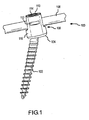
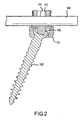
- FIG. 1 shows a perspective view of system 100 while FIG. 2 shows a cross-sectional view of system 100.
- System 100 includes a bone screw 102, a housing 104, an insert 106, a rod 108, and a compressive member, such as, a setscrew 110.
- Housing 104 may contain one or more first mating surfaces 112. First mating surfaces 112 are designed to mate with a tool (not specifically shown).
- setscrew 110 typically has one or more second mating surface 114 to mate with a tool (also not shown). As shown in FIG.
- first mating surfaces 112 are actually slots on an outer surface 116 of housing 104. While shown as slots, first mating surfaces 112 may be any number of designs including one or more dimples, hex detents, or other equivalent mechanisms as are known in the art. Second mating surface 114 is shown with a hex shape to accept a hex driver useful in threading the setscrew. Of course, one of ordinary skill in the art would recognize other and equivalent first and second mating surfaces 112, 114 are possible.
- Housing 104 may be referred to as a coupling device, seat, or anchor.
- Housing 104 has a bone facing surface 302, at least one sidewall 304 having an outer surface 116 and an inner surface 306 (best seen in FIG. 4 ), first mating surfaces 112, a pair of opposed slots 308 in sidewall 304, a top edge 310, and a through hole 312 extending from top edge 310, to bone facing surface 302.
- Housing 104 can be considered to have a rod receiving section 402 and a screw receiving section 404.
- housing 104 is shown with one cylindrically shaped sidewall 304. It is believed providing housing 104 as a cylindrical shape reduces the profile of the device, but other shapes are possible, such as cubic or the like. If housing 104 had multiple sidewalls 304, the edges between the multiple sides should be beveled or rounded to inhibit tissue trauma.
- inner surface 306 has first threads 406 extending partially along inner surface 306. As will be explained below, first threads 406 allow setscrew 110 to be threaded on housing 104. Slots 308 generally have a width W1 sufficiently wide to accept rod 108. Slots 308 have an insert seating surface 408, which will be explained further below. An insert groove 410 is provided about insert seating surface 408. Insert groove 410 allows provides a mechanism to lock and stabilize insert 106, as will be explained below.
- rod receiving section 402 provides a channel for a single rod 108 to traverse housing 104 from slot 308 to slot 308.
- Housing 104 could be easily converted to provide multiple rod guides.
- housing 104 could have a second set of opposed slots substantially parallel to slots 308.
- a rod cap/seat could be installed below threads 406 and above insert seating surface 408. The rod cap/seat would provide a cap side operatively sized and shaped to fit about rod 108 opposite the insert seating surface 408.
- the rod cap/seat provide a second seating surface operatively sized and shaped to fit about a second rod aligned substantially above rod 108.
- Setscrew 110 would provide compressive force to the substantially aligned rod, which would correspondingly provide compressive force to rod 108 and insert 106, etc.
- inner surface 306 has a screw head seating surface 412.
- Surface 412 has a shape corresponding to the screw head, described below.
- Surface 412 has an upper lip 414 and a lower lip 416.
- Upper lip 414 and lower lip 416 could comprise a beveled edge and/or protrusions.
- Upper lip 414, lower lip 416, and surface 412 cooperatively engage the screw head to allow a polyaxial engagement of the screw 102, which will be described below.
- upper lip 414 has a first diameter d1 and lower lip 416 has a second diameter d2.
- First diameter d1 is larger than second diameter d2.
- Inner surface 306 terminates at bone facing surface 302.
- inner surface 306 flares out from second diameter d2 such that the bone side of through hole 312 has a third diameter d3 larger than second diameter d2, but generally smaller than first diameter d1.
- Outer surface 116 is generally perpendicular to top edge 310 and bone facing surface 302 to conserve space.
- bone facing surface 302 may have a rounded transition 418 between bone facing surface 302 and outer surface 116 to inhibit trauma to tissue.
- top edge 310 has beveled or rounded edges.
- through hole 312 at top edge 310 has a fourth diameter d4. Diameter d4 is sufficiently large to accept the head of screw 102 and setscrew 110.
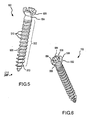
- Bone screw 102 will now be described with reference to FIGS. 5 and 6 .
- Bone screw 102 has a threaded portion 502, a transition portion 504, and a head portion 506.
- Threaded portion 502 can use any conventional thread, but as shown, threaded portion 502 has a shaft 508 and threads 510 machined such that shaft 508 has an increasing diameter from the tip 512 to transition portion 504. Further, threads 510 become relatively thicker towards transition portion 504. Designing threaded portion 502 in this fashion increases the frictional engagement of bone screw 102 in bone and generally increases the screw strength.
- Transition portion 504 comprises the portion of bone screw 102 between threaded portion 502 and head portion 506. Transition portion 504 could be integrated into threaded portion 502. Transition portion 504 may be straight, curved, bowed, flared, or the like to transition threaded portion 502 to head portion 506.
- FIG. 6 shows head 506 of screw 102 in more detail.
- Head 506 has a housing engaging surface 602, an insert engaging surface 604, a top edge 606, and at least one third mating surface 608, which in this case comprises a plurality of grooves.
- Insert engaging surface 604 has a shape corresponding to the insert, as is explained further below.
- Third mating surface 608 is designed to allow a surgeon to thread screw 102 into bone using a driver.
- Housing engaging surface 602 has a shape corresponding to screw head seating surface 412. As shown, screw head seating surface 412 is convex in shape to mate with the concave shaped housing engaging surface 602. Housing engaging surface 602 can rotate relative to screw head seating surface 412. If designed as protrusions, upper lip 414 and lower lip 416 may provide limits on the rotation or angle of screw 102 relative to housing 104.
- Insert 106 comprises a screw head engaging surface 702, a transition section 704, and an elongated rod rest 706.
- Screw head engaging surface 702 has a shape that corresponds to insert engaging surface 604.
- insert engaging surface 604 is concave shaped to mate with convexly shaped screw head engaging surface 702.
- the corresponding surfaces 604 and 702 allow polyaxial orientation of screw 102 relative to insert 106.
- insert 106 and housing 104 remain aligned or substantially aligned.
- Transition section 704 is a provides a transition between screw head engaging surface 702 and elongated rod rest 706.
- Transition section 704 is somewhat narrower than the largest diameter of surface 702 to increase the rotational engagement between the screw and insert.
- Elongated rod rest 706 traverses housing 104 between opposing slots 308.
- Elongated rod rest 706 has a bottom surface 708 shaped to fit in insert seating surface 408.
- Elongated rod rest 706 is shaped to receive rod 108.
- rod rest 706 may be solid as shown or substantially void as a matter of design choice; however, it is believed providing a substantially solid rest provides a more stable construct.
- elongated rod rest 706 has a plurality of tabs 902 formed by slots 904. Each tab 902 has a protrusion 906. Insert 106 is placed in housing 104 by compressing tabs 902 as allowed by slots 904 toward rest 706. When compressed, protrusions 906 are a distance d5 apart, where d5 is less than W1. When compressed, insert 106 can be fitted into through hole 312 of housing 106 until screw head engaging surface 702 rests on insert engaging surface 604.
- protrusion 906 engage groove 410 ( FIG. 4 ) to lock and stabilize insert 106 in housing 104.
- Screw 102 is inserted through through hole 312. Screw 102 is partially driven into bone, not specifically shown in the FIG, until bone facing surface 302 seats on the bone and housing engaging surface 602 engages screw head seating surface 412. Screw 102 may be angled relative to a vertical axis V of housing 104. Also, housing is aligned such that opposing slots 308 will align with rod 108. Screw 102 has a polyaxial orientation relative to insert 106. Rod 108 is placed on elongated rod rest 706 and setscrew 110 is threaded into through hole 312 until setscrew 110 contacts rod 108 placing the construct under sufficient compression to stabilize and lock the device in place.
- threads 406 substantially terminate at a top surface 1002 of rod 102. This allows sufficient thread to provide the necessary force without providing unnecessary thread. Thread 406 could stop substantially at or above top surface 1002, but in that case, setscrew 110 should be designed with a boss. The thread design reduces the spreading of the housing 104 when the setscrew is tightened to rod 108.
- the above construct is very stable in part because of the surface-to-surface contacts provided by various engaging surface. Further stability is provided in some instances by the insert coupling with a groove in the housing and providing a surface-to-surface contact between the rod and insert.
Landscapes
- Health & Medical Sciences (AREA)
- Orthopedic Medicine & Surgery (AREA)
- Life Sciences & Earth Sciences (AREA)
- Neurology (AREA)
- Surgery (AREA)
- Heart & Thoracic Surgery (AREA)
- Engineering & Computer Science (AREA)
- Biomedical Technology (AREA)
- Nuclear Medicine, Radiotherapy & Molecular Imaging (AREA)
- Medical Informatics (AREA)
- Molecular Biology (AREA)
- Animal Behavior & Ethology (AREA)
- General Health & Medical Sciences (AREA)
- Public Health (AREA)
- Veterinary Medicine (AREA)
- Surgical Instruments (AREA)
Description
- The present invention relates to spinal fixation devices and more particularly to a pedicle screw and rod fixation assembly useful in stabilizing a spine of a patient.
- Over the years, several techniques and systems have been developed for correcting spinal injuries and/or degenerative spinal processes. Spinal correction frequently requires stabilizing a portion of the spine to facilitate fusing portions of the spine or other correction methodologies. Medical correction of this type is frequently employed for many spinal conditions, such as, for example, degenerative disc disease, scoliosis, spinal stenosis, or the like. Frequently, these corrections also require the use of implants, such as, bone grafts. Stabilizing the spine allows bone growth between vertebral bodies such that a portion of the spine is fused into a solitary unit.
- Several techniques and systems have been developed for correcting and stabilizing the spine and facilitating fusion at various levels of the spine. In one type of system, a rod is disposed longitudinally along the length of the spine in the region of concern. The rod is arranged according to the anatomy and the correction desired. In this system, the rod is aligned along the spine and engages various vertebrae along its length. The rod engages, or more typically the parallel rods engage, the spine using fixation elements, such as, anchors attached to vertebral bodies by a bone screw.
- Anatomy and correction frequently require aligning the rod and screw at various angles along the length of the portion of correction. In order to provide this alignment, polyaxial screws/anchors have been developed. Many variations of polyaxial screw and rod fixation systems exist on the market today.
- Despite the fact that numerous polyaxial rod fixation systems are on the market, improvement of the devices is desirable. Accordingly, there is a need for a screw and rod fixation system that provides a strong, effective, and secure lock of the screw and rod in the desired position and angle. Additionally, there is a need for a screw head securing mechanism or device that is minimal in size and has a reduced amount of components to provide for a simpler, more effective, and less cumbersome device for fixing screws.
- Document
US6540748 discloses a surgical screw system for use with implantation rods including a screw member, a receiver member, a pressure cap and a locking device. - Document
US6626908 discloses a pedicle attachment assembly including a pedicle attachment device having a head. - To attain the advantages and in accordance with the purpose of the invention, as embodied and broadly described herein, a screw and rod fixation system is provided. The screw and rod fixation system comprises a bone screw having a threaded portion, a transition, and a head comprising a housing engaging surface and an insert engaging surface. The bone screw is provided in a housing with a bone facing surface and a top edge and a sidewall extending therebetween. A through hole extends from the top edge to the bone facing surface and a pair of opposing slots reside proximate the top edge. The housing has a screw head seating surface that is shaped to cooperatively engage the housing engaging surface to allow polyaxial orientation of the bone screw relative to a vertical axis of the housing. A housing couples to the bone screw and housing. The insert comprises a screw head engaging surface to cooperatively engage the insert engaging surface to allow polyaxial orientation of the bone screw relative to a vertical axis of the housing and an elongate rod rest shaped to seat a portion of the elongated rod, the elongated rod rest traversing the housing between the pair of opposing slots. An elongated rod traverses the housing between the pair of opposed slots and seated in the elongated rod rest.
- The present invention further provides an insert useful in a device that couples spinal rods to vertebral bodies. The insert comprises a bone screw engaging surface and an elongated rest coupled to the bone screw engaging surface having an outer edge and a bottom surface opposite the elongated rest. A transition portion connects the bone screw engaging surface and the elongated rest. The insert cooperatively engage a bone screw to allow polyaxial orientation of the bone screw relative to the insert.
- The foregoing and other features, utilities and advantages of the invention will be apparent from the following more particular description of a preferred embodiment of the invention as illustrated in the accompanying drawings.
- The accompanying drawings illustrate various embodiments of the present invention and are a part of the specification. The illustrated embodiments are merely examples and illustrations of the present invention and do not limit the scope of the invention.
-
FIG. 1 shows a perspective view of a screw and rod fixation system in accordance with an embodiment of the present invention; -
FIG. 2 shows a cross-sectional view of the system ofFIG. 1 ; -
FIG. 3 shows a perspective view of a housing associated with an embodiment of the present invention shown inFIG. 1 ; -
FIG. 4 shows a cross-sectional view of the housing ofFIG. 3 ; -
FIG. 5 shows a perspective view of a bone screw associated with an embodiment of the present invention shown inFIG. 1 ; -
FIG. 6 shows another perspective view of the bone screw ofFIG. 5 ; -
FIG. 7 shows a perspective view of an insert associated with an embodiment of the present invention shown inFIG. 1 ; -
FIG. 8 shows a cross-sectional view of the insert ofFIG. 7 ; -
FIG. 9 shows a top elevation view of the insert ofFIG. 7 ; and -
FIG. 10 shows a detailed cross-sectional view of the construct shown inFIG. 2 . - Referring now to
FIG. 1 andFIG. 2 , and in accordance with certain embodiments of the present invention, a screw androd fixation system 100 is shown.FIG. 1 shows a perspective view ofsystem 100 whileFIG. 2 shows a cross-sectional view ofsystem 100.System 100 includes abone screw 102, ahousing 104, aninsert 106, arod 108, and a compressive member, such as, asetscrew 110.Housing 104 may contain one or morefirst mating surfaces 112.First mating surfaces 112 are designed to mate with a tool (not specifically shown). Also,setscrew 110 typically has one or moresecond mating surface 114 to mate with a tool (also not shown). As shown inFIG. 1 ,first mating surfaces 112 are actually slots on anouter surface 116 ofhousing 104. While shown as slots,first mating surfaces 112 may be any number of designs including one or more dimples, hex detents, or other equivalent mechanisms as are known in the art.Second mating surface 114 is shown with a hex shape to accept a hex driver useful in threading the setscrew. Of course, one of ordinary skill in the art would recognize other and equivalent first andsecond mating surfaces - Referring now to
FIGS. 3 and4 ,housing 104 is described in more detail.Housing 104 may be referred to as a coupling device, seat, or anchor.Housing 104 has abone facing surface 302, at least onesidewall 304 having anouter surface 116 and an inner surface 306 (best seen inFIG. 4 ),first mating surfaces 112, a pair ofopposed slots 308 insidewall 304, atop edge 310, and a throughhole 312 extending fromtop edge 310, tobone facing surface 302.Housing 104 can be considered to have arod receiving section 402 and ascrew receiving section 404. - Notice,
housing 104 is shown with one cylindrically shapedsidewall 304. It is believed providinghousing 104 as a cylindrical shape reduces the profile of the device, but other shapes are possible, such as cubic or the like. Ifhousing 104 hadmultiple sidewalls 304, the edges between the multiple sides should be beveled or rounded to inhibit tissue trauma. - Referring first to
rod receiving section 402,inner surface 306 hasfirst threads 406 extending partially alonginner surface 306. As will be explained below,first threads 406 allowsetscrew 110 to be threaded onhousing 104.Slots 308 generally have a width W1 sufficiently wide to acceptrod 108.Slots 308 have aninsert seating surface 408, which will be explained further below. Aninsert groove 410 is provided aboutinsert seating surface 408.Insert groove 410 allows provides a mechanism to lock and stabilizeinsert 106, as will be explained below. - As shown in
FIG. 4 ,rod receiving section 402 provides a channel for asingle rod 108 to traversehousing 104 fromslot 308 to slot 308. In some instances, it may be difficult to provide asingle rod 108 that can traverse the entire length of the spine necessitating multiple rods.Housing 104 could be easily converted to provide multiple rod guides. For example,housing 104 could have a second set of opposed slots substantially parallel toslots 308. Alternatively (but not shown), a rod cap/seat could be installed belowthreads 406 and aboveinsert seating surface 408. The rod cap/seat would provide a cap side operatively sized and shaped to fit aboutrod 108 opposite theinsert seating surface 408. The rod cap/seat provide a second seating surface operatively sized and shaped to fit about a second rod aligned substantially aboverod 108.Setscrew 110 would provide compressive force to the substantially aligned rod, which would correspondingly provide compressive force torod 108 and insert 106, etc. - Referring to screw receiving
section 404,inner surface 306 has a screwhead seating surface 412.Surface 412 has a shape corresponding to the screw head, described below.Surface 412 has anupper lip 414 and alower lip 416.Upper lip 414 andlower lip 416 could comprise a beveled edge and/or protrusions.Upper lip 414,lower lip 416, andsurface 412 cooperatively engage the screw head to allow a polyaxial engagement of thescrew 102, which will be described below. As shown,upper lip 414 has a first diameter d1 andlower lip 416 has a second diameter d2. First diameter d1 is larger than second diameter d2.Inner surface 306 terminates atbone facing surface 302. As shown,inner surface 306 flares out from second diameter d2 such that the bone side of throughhole 312 has a third diameter d3 larger than second diameter d2, but generally smaller than first diameter d1.Outer surface 116 is generally perpendicular totop edge 310 andbone facing surface 302 to conserve space. As shown,bone facing surface 302 may have a roundedtransition 418 betweenbone facing surface 302 andouter surface 116 to inhibit trauma to tissue. Also,top edge 310 has beveled or rounded edges. Lastly, throughhole 312 attop edge 310 has a fourth diameter d4. Diameter d4 is sufficiently large to accept the head ofscrew 102 andsetscrew 110. -
Bone screw 102 will now be described with reference toFIGS. 5 and 6 .Bone screw 102 has a threadedportion 502, atransition portion 504, and ahead portion 506. Threadedportion 502 can use any conventional thread, but as shown, threadedportion 502 has ashaft 508 andthreads 510 machined such thatshaft 508 has an increasing diameter from thetip 512 to transitionportion 504. Further,threads 510 become relatively thicker towardstransition portion 504. Designing threadedportion 502 in this fashion increases the frictional engagement ofbone screw 102 in bone and generally increases the screw strength. -
Transition portion 504 comprises the portion ofbone screw 102 between threadedportion 502 andhead portion 506.Transition portion 504 could be integrated into threadedportion 502.Transition portion 504 may be straight, curved, bowed, flared, or the like to transition threadedportion 502 tohead portion 506. -
FIG. 6 shows head 506 ofscrew 102 in more detail.Head 506 has ahousing engaging surface 602, aninsert engaging surface 604, atop edge 606, and at least onethird mating surface 608, which in this case comprises a plurality of grooves. Insert engagingsurface 604 has a shape corresponding to the insert, as is explained further below.Third mating surface 608 is designed to allow a surgeon tothread screw 102 into bone using a driver. -
Housing engaging surface 602 has a shape corresponding to screwhead seating surface 412. As shown, screwhead seating surface 412 is convex in shape to mate with the concave shapedhousing engaging surface 602.Housing engaging surface 602 can rotate relative to screwhead seating surface 412. If designed as protrusions,upper lip 414 andlower lip 416 may provide limits on the rotation or angle ofscrew 102 relative tohousing 104. -
Insert 106 will now be described with reference toFIGS. 7, 8 , and9 .Insert 106 comprises a screwhead engaging surface 702, atransition section 704, and anelongated rod rest 706. Screwhead engaging surface 702 has a shape that corresponds to insert engagingsurface 604. In this case, insert engagingsurface 604 is concave shaped to mate with convexly shaped screwhead engaging surface 702. The corresponding surfaces 604 and 702 allow polyaxial orientation ofscrew 102 relative to insert 106. Moreover, insert 106 andhousing 104 remain aligned or substantially aligned.Transition section 704 is a provides a transition between screwhead engaging surface 702 andelongated rod rest 706.Transition section 704 is somewhat narrower than the largest diameter ofsurface 702 to increase the rotational engagement between the screw and insert. -
Elongated rod rest 706 traverseshousing 104 between opposingslots 308.Elongated rod rest 706 has abottom surface 708 shaped to fit ininsert seating surface 408.Elongated rod rest 706 is shaped to receiverod 108. Optionally,rod rest 706 may be solid as shown or substantially void as a matter of design choice; however, it is believed providing a substantially solid rest provides a more stable construct. - Referring now to
FIG. 9 , a top elevation view ofinsert 106 is provided. As shown,elongated rod rest 706 has a plurality oftabs 902 formed byslots 904. Eachtab 902 has aprotrusion 906.Insert 106 is placed inhousing 104 by compressingtabs 902 as allowed byslots 904 towardrest 706. When compressed,protrusions 906 are a distance d5 apart, where d5 is less than W1. When compressed, insert 106 can be fitted into throughhole 312 ofhousing 106 until screwhead engaging surface 702 rests oninsert engaging surface 604. Oncesurface 702 andsurface 604 are in place, the compression ontabs 902 is released andtabs 902 return to the uncompressed state such thatprotrusion 906 are a distance d6, where d6 is greater than d5 and W1.Protrusions 906 engage groove 410 (FIG. 4 ) to lock and stabilizeinsert 106 inhousing 104. - With reference to
FIG. 10 , placement ofsystem 100 will be explained. First, screw 102 is inserted through throughhole 312.Screw 102 is partially driven into bone, not specifically shown in the FIG, untilbone facing surface 302 seats on the bone andhousing engaging surface 602 engages screwhead seating surface 412.Screw 102 may be angled relative to a vertical axis V ofhousing 104. Also, housing is aligned such that opposingslots 308 will align withrod 108.Screw 102 has a polyaxial orientation relative to insert 106.Rod 108 is placed on elongatedrod rest 706 andsetscrew 110 is threaded into throughhole 312 untilsetscrew 110contacts rod 108 placing the construct under sufficient compression to stabilize and lock the device in place. As shown,threads 406 substantially terminate at atop surface 1002 ofrod 102. This allows sufficient thread to provide the necessary force without providing unnecessary thread.Thread 406 could stop substantially at or abovetop surface 1002, but in that case,setscrew 110 should be designed with a boss. The thread design reduces the spreading of thehousing 104 when the setscrew is tightened torod 108. - The above construct is very stable in part because of the surface-to-surface contacts provided by various engaging surface. Further stability is provided in some instances by the insert coupling with a groove in the housing and providing a surface-to-surface contact between the rod and insert.
- While the invention has been particularly shown and described with reference to an embodiment thereof, it will be understood by those skilled in the art that various other changes in the form and details may be made without departing from the scope of the invention as defined by the appended claims.
Claims (22)
- A system useful in spinal corrective procedures, the system comprising:a bone screw (102);a housing (104);an insert (106);an elongated rod (108);a compressive member (110);the bone screw (102) comprising :a threaded portion (502), a transition portion (504); anda head (506) comprising a housing engaging surface (602) and an insert engaging surface (604);the housing (104) comprising :a bone facing surface (302)and a top edge (310) with at least one sidewall (304) extending there between;a through hole (312) extending from the top edge (310) to the bone facing surface (302);at least a pair of opposing slots (308) proximate the top edge (310);a screw head seating surface (412), the screw head seating surface (412) shaped to cooperatively engage the housing engaging surface (602) to allow polyaxial orientation of the bone screw (102) relative to a vertical axis (V) of the housing (104); and an inner surface (306) comprising a groove (410), the through hole (312) defining a first transverse inside diameter (d1) nearer the top edge and the groove defining a second transverse inside diameter (d2) smaller than the first transverse diameter (d1) further from the top edge;characterized by:the insert (106) comprising:a screw head engaging surface (702), the screw head engaging surface (702) shaped to cooperatively engage the insert engaging surface (604) to allow polyaxial orientation of the bone screw (102) relative to a vertical axis (V) of the housing (104); and a rod rest (706) shaped to seat a portion of the elongated rod (108), the rod rest aligning with the pair of opposing slots (308); andtabs (902) formed by slots (904) releasably compressible between a first position and a second position each tab having a protrusion (906), the insert being passable axially into the through hole (312) through the first traverse diameter (d1) and into the groove (410) with the protrusion (906) in the first position and the insert (106) being retained in the groove (410) with the protrusion in the second position;wherein the elongated rod (108) is seatable on the rod rest (706) and securable by the compressive member (110).
- The system of claim 1, wherein the bone screw comprises a shaft (508) having threads (510), the shaft expanding radially outward from the tip (512) to the transition (504) between a threaded portion (502) and a head portion (506).
- The system of claim 1, wherein the housing engaging surface (602) comprises a convexly shaped surface.
- The system of claim 3, wherein the insert engaging surface (604) comprises a concavely shaped surface.
- The system of claim 3, wherein the screw head seating surface (412) comprises a concavely shaped surface corresponding to the convexly shaped housing engaging surface (602).
- The system of claim 4, wherein the screw head engaging surface (702) comprises a convexly shaped surface corresponding to the concavely shaped insert engaging surface (604).
- The system of claim 1, wherein the bone screw further comprises a tool-mating surface (608) so a surgeon can thread the bone screw in bone.
- The system of claim 1, wherein the housing comprises:a rod receiving section (402) and a screw receiving section (404); andthe screw receiving section comprising an upper lip (414) and a lower lip (416) about the screw head seating surface (412).
- The system of claim 8, wherein the upper lip (414) and the lower lip (416) limit the rotation of the housing engaging surface (602).
- The system of claim 8, wherein the bone facing surface (302) connects to the at least one sidewall (304) by a beveled section (418).
- The system of claim 8, wherein an inner surface (306) flares radially outward from the lower lip (416) to the bone facing surface (302).
- The system of claim 1, wherein the at least one protrusion (906) comprises a portion of a tab (902) coupled to the rod rest (706) and separated from the rod rest (706) by a slot (904), and the tab (902) is subjectable to a compressive force that allows the insert (106) to be inserted into the housing (104) when the compressive force is applied and the protrusion (906) engages the groove (410) when the compressive force is removed.
- The system according to claim 1, wherein the pair of opposing slots (308) terminate in an insert seating surface (408) having a shape corresponding to a bottom of the rod rest (706) and the rod rest (706) traverses the housing (104) and extends into the pair of opposing slots (308) above the insert seating surface (408).
- The system according to claim 1, further comprising the compressive member (110) having first threads; and wherein the housing (104) comprises an inner surface (306) having second threads (406) proximate the top edge (310) corresponding to the first threads such that the compressive member (110) can be threaded in the through hole and provide a compressive force on the elongated rod (108).
- The system according to claim 14, wherein the second threads (406) extend from the top edge (310) to substantially about a top of the elongated rod (108).
- The system according to claim 14, wherein the second threads (406) extend from the top edge (310) to substantially above a top of the elongated rod (108), and wherein the compressive member is a setscrew, which setscrew comprises a boss extending below the first threads such that the boss contacts the elongated rod.
- The system according to claim 1, wherein:the bone screw (102) comprises a plurality of bone screws;the housing (104) comprises a plurality of housings, wherein the plurality of housings corresponds to the plurality of bone screws;the insert (106) comprises a plurality of inserts, wherein the plurality of inserts corresponds to the plurality of housings;the compressive member (110) comprises a plurality of compressive members, wherein the plurality of compressive members corresponds to the plurality of housings; andthe elongated rod (108) comprises at least one elongated rod that traverses a plurality of said plurality of housings.
- The system according to claim 1, wherein:the bone screw (102) comprises a pedicle screw; andthe compressive member (110) comprises a setscrew.
- The system according to claim 1, wherein the insert (106) further comprises a transition portion (704) coupling the screw head engaging surface (702) and the rod rest (706) and wherein the head engaging surface (702) comprises more than half a spherical shape such that the transition portion (704) is narrower than the diameter of the spherical shape allowing the bone screw (102) and the insert (106) additional rotation.
- The system according to claim 1, wherein the housing (104) comprises: a rod receiving section (402) and a screw receiving section (404); and the screw receiving section comprising an upper lip (414) and a lower lip (416) about the screw head seating surface (412), wherein the upper lip (414) and the lower lip (416) limit the rotation of the bone screw relative to the housing (104).
- The system according to claim 1, the insert (106) comprising:an outer edge and a bottom surface (708) opposite the rod rest (706);the screw head engaging surface (702) coupled to the rod rest (706) including a convex protrusion cooperatively engageable with a bone screw (102) to allow polyaxial orientation of the bone screw (102) relative to the insert (106), the convex protrusion having a first transverse diameter (d1) in a first plane substantially parallel to the rod rest (706);a transition portion (704) connecting the screw head engaging surface (702) and the rod rest (706), the transition portion (704) comprising a second transverse diameter (d2) in a second plane substantially parallel to the first plane smaller than the first transverse diameter (d1) to define a necked region between the convex portion and the rod rest; andat least one portion attached to the outer edge of the rod rest (706) to abut the groove (410) in the housing (104) to lock the insert in the construct; andthe rod rest (706) having a rod engaging surface with a shape to provide a surface-to-surface contact between the rod rest (706) and a the elongated rod (108).
- The system according to claim 21, wherein the bottom surface (708) of the rod rest (706) further comprises a shape to provide a surface-to-surface contact between the rod rest (708) and a seating surface (408) of the pair of opposed slots (308) in the housing (104).
Applications Claiming Priority (2)
| Application Number | Priority Date | Filing Date | Title |
|---|---|---|---|
| US10/915,902 US7766945B2 (en) | 2004-08-10 | 2004-08-10 | Screw and rod fixation system |
| PCT/US2005/027598 WO2006020474A2 (en) | 2004-08-10 | 2005-08-02 | Screw and rod fixation system |
Publications (3)
| Publication Number | Publication Date |
|---|---|
| EP1824398A2 EP1824398A2 (en) | 2007-08-29 |
| EP1824398A4 EP1824398A4 (en) | 2009-04-08 |
| EP1824398B1 true EP1824398B1 (en) | 2012-11-14 |
Family
ID=35800960
Family Applications (1)
| Application Number | Title | Priority Date | Filing Date |
|---|---|---|---|
| EP05778961A Expired - Lifetime EP1824398B1 (en) | 2004-08-10 | 2005-08-02 | Screw and rod fixation system |
Country Status (3)
| Country | Link |
|---|---|
| US (1) | US7766945B2 (en) |
| EP (1) | EP1824398B1 (en) |
| WO (1) | WO2006020474A2 (en) |
Families Citing this family (181)
| Publication number | Priority date | Publication date | Assignee | Title |
|---|---|---|---|---|
| US7833250B2 (en) | 2004-11-10 | 2010-11-16 | Jackson Roger P | Polyaxial bone screw with helically wound capture connection |
| US8377100B2 (en) | 2000-12-08 | 2013-02-19 | Roger P. Jackson | Closure for open-headed medical implant |
| US6726689B2 (en) * | 2002-09-06 | 2004-04-27 | Roger P. Jackson | Helical interlocking mating guide and advancement structure |
| US8292926B2 (en) | 2005-09-30 | 2012-10-23 | Jackson Roger P | Dynamic stabilization connecting member with elastic core and outer sleeve |
| US10729469B2 (en) | 2006-01-09 | 2020-08-04 | Roger P. Jackson | Flexible spinal stabilization assembly with spacer having off-axis core member |
| US8353932B2 (en) | 2005-09-30 | 2013-01-15 | Jackson Roger P | Polyaxial bone anchor assembly with one-piece closure, pressure insert and plastic elongate member |
| US7862587B2 (en) | 2004-02-27 | 2011-01-04 | Jackson Roger P | Dynamic stabilization assemblies, tool set and method |
| US10258382B2 (en) | 2007-01-18 | 2019-04-16 | Roger P. Jackson | Rod-cord dynamic connection assemblies with slidable bone anchor attachment members along the cord |
| US6740086B2 (en) | 2002-04-18 | 2004-05-25 | Spinal Innovations, Llc | Screw and rod fixation assembly and device |
| US11224464B2 (en) | 2002-05-09 | 2022-01-18 | Roger P. Jackson | Threaded closure with inwardly-facing tool engaging concave radiused structures and axial through-aperture |
| US8257402B2 (en) * | 2002-09-06 | 2012-09-04 | Jackson Roger P | Closure for rod receiving orthopedic implant having left handed thread removal |
| US20060009773A1 (en) * | 2002-09-06 | 2006-01-12 | Jackson Roger P | Helical interlocking mating guide and advancement structure |
| US8876868B2 (en) * | 2002-09-06 | 2014-11-04 | Roger P. Jackson | Helical guide and advancement flange with radially loaded lip |
| US8282673B2 (en) * | 2002-09-06 | 2012-10-09 | Jackson Roger P | Anti-splay medical implant closure with multi-surface removal aperture |
| WO2004089245A2 (en) * | 2003-04-04 | 2004-10-21 | Theken Surgical, Llc | Bone anchor |
| US8540753B2 (en) | 2003-04-09 | 2013-09-24 | Roger P. Jackson | Polyaxial bone screw with uploaded threaded shank and method of assembly and use |
| US6716214B1 (en) | 2003-06-18 | 2004-04-06 | Roger P. Jackson | Polyaxial bone screw with spline capture connection |
| US7621918B2 (en) | 2004-11-23 | 2009-11-24 | Jackson Roger P | Spinal fixation tool set and method |
| US7377923B2 (en) | 2003-05-22 | 2008-05-27 | Alphatec Spine, Inc. | Variable angle spinal screw assembly |
| US7967850B2 (en) | 2003-06-18 | 2011-06-28 | Jackson Roger P | Polyaxial bone anchor with helical capture connection, insert and dual locking assembly |
| US7776067B2 (en) | 2005-05-27 | 2010-08-17 | Jackson Roger P | Polyaxial bone screw with shank articulation pressure insert and method |
| US8398682B2 (en) | 2003-06-18 | 2013-03-19 | Roger P. Jackson | Polyaxial bone screw assembly |
| US8137386B2 (en) | 2003-08-28 | 2012-03-20 | Jackson Roger P | Polyaxial bone screw apparatus |
| US8257398B2 (en) | 2003-06-18 | 2012-09-04 | Jackson Roger P | Polyaxial bone screw with cam capture |
| US7766915B2 (en) | 2004-02-27 | 2010-08-03 | Jackson Roger P | Dynamic fixation assemblies with inner core and outer coil-like member |
| US8377102B2 (en) | 2003-06-18 | 2013-02-19 | Roger P. Jackson | Polyaxial bone anchor with spline capture connection and lower pressure insert |
| US8092500B2 (en) * | 2007-05-01 | 2012-01-10 | Jackson Roger P | Dynamic stabilization connecting member with floating core, compression spacer and over-mold |
| US8936623B2 (en) | 2003-06-18 | 2015-01-20 | Roger P. Jackson | Polyaxial bone screw assembly |
| US8366753B2 (en) * | 2003-06-18 | 2013-02-05 | Jackson Roger P | Polyaxial bone screw assembly with fixed retaining structure |
| US11419642B2 (en) | 2003-12-16 | 2022-08-23 | Medos International Sarl | Percutaneous access devices and bone anchor assemblies |
| US7527638B2 (en) | 2003-12-16 | 2009-05-05 | Depuy Spine, Inc. | Methods and devices for minimally invasive spinal fixation element placement |
| US7179261B2 (en) * | 2003-12-16 | 2007-02-20 | Depuy Spine, Inc. | Percutaneous access devices and bone anchor assemblies |
| WO2005092218A1 (en) | 2004-02-27 | 2005-10-06 | Jackson Roger P | Orthopedic implant rod reduction tool set and method |
| US7160300B2 (en) | 2004-02-27 | 2007-01-09 | Jackson Roger P | Orthopedic implant rod reduction tool set and method |
| US11241261B2 (en) | 2005-09-30 | 2022-02-08 | Roger P Jackson | Apparatus and method for soft spinal stabilization using a tensionable cord and releasable end structure |
| US8152810B2 (en) | 2004-11-23 | 2012-04-10 | Jackson Roger P | Spinal fixation tool set and method |
| DE102004046163A1 (en) | 2004-08-12 | 2006-02-23 | Columbus Trading-Partners Pos und Brendel GbR (vertretungsberechtigte Gesellschafter Karin Brendel, 95503 Hummeltal und Bohumila Pos, 95445 Bayreuth) | Child seat for motor vehicles |
| US7651502B2 (en) | 2004-09-24 | 2010-01-26 | Jackson Roger P | Spinal fixation tool set and method for rod reduction and fastener insertion |
| US7722654B2 (en) * | 2004-10-05 | 2010-05-25 | Warsaw Orthopedic, Inc. | Spinal implants with multi-axial anchor assembly and methods |
| JP2008519656A (en) | 2004-11-10 | 2008-06-12 | ロジャー・ピー・ジャクソン | Helical guide and forward flange with break extension |
| US8926672B2 (en) | 2004-11-10 | 2015-01-06 | Roger P. Jackson | Splay control closure for open bone anchor |
| US9980753B2 (en) | 2009-06-15 | 2018-05-29 | Roger P Jackson | pivotal anchor with snap-in-place insert having rotation blocking extensions |
| US8444681B2 (en) | 2009-06-15 | 2013-05-21 | Roger P. Jackson | Polyaxial bone anchor with pop-on shank, friction fit retainer and winged insert |
| WO2006057837A1 (en) | 2004-11-23 | 2006-06-01 | Jackson Roger P | Spinal fixation tool attachment structure |
| US9168069B2 (en) | 2009-06-15 | 2015-10-27 | Roger P. Jackson | Polyaxial bone anchor with pop-on shank and winged insert with lower skirt for engaging a friction fit retainer |
| US8308782B2 (en) | 2004-11-23 | 2012-11-13 | Jackson Roger P | Bone anchors with longitudinal connecting member engaging inserts and closures for fixation and optional angulation |
| US9216041B2 (en) | 2009-06-15 | 2015-12-22 | Roger P. Jackson | Spinal connecting members with tensioned cords and rigid sleeves for engaging compression inserts |
| US7875065B2 (en) * | 2004-11-23 | 2011-01-25 | Jackson Roger P | Polyaxial bone screw with multi-part shank retainer and pressure insert |
| US8172855B2 (en) | 2004-11-24 | 2012-05-08 | Abdou M S | Devices and methods for inter-vertebral orthopedic device placement |
| US7476239B2 (en) * | 2005-05-10 | 2009-01-13 | Jackson Roger P | Polyaxial bone screw with compound articulation |
| US7901437B2 (en) | 2007-01-26 | 2011-03-08 | Jackson Roger P | Dynamic stabilization member with molded connection |
| US10076361B2 (en) | 2005-02-22 | 2018-09-18 | Roger P. Jackson | Polyaxial bone screw with spherical capture, compression and alignment and retention structures |
| US12102357B2 (en) | 2005-02-22 | 2024-10-01 | Roger P. Jackson | Pivotal bone anchor assembly with cannulated shank having a planar top surface and method of assembly |
| US20060235385A1 (en) * | 2005-03-31 | 2006-10-19 | Dale Whipple | Low profile polyaxial screw |
| US20060264252A1 (en) * | 2005-05-23 | 2006-11-23 | White Gehrig H | System and method for providing a host console for use with an electronic card game |
| US12357348B2 (en) | 2005-09-30 | 2025-07-15 | Roger P. Jackson | Method of assembling a pivotal bone anchor assembly with press-in-place insert |
| US8105368B2 (en) | 2005-09-30 | 2012-01-31 | Jackson Roger P | Dynamic stabilization connecting member with slitted core and outer sleeve |
| US7704271B2 (en) * | 2005-12-19 | 2010-04-27 | Abdou M Samy | Devices and methods for inter-vertebral orthopedic device placement |
| US8057519B2 (en) | 2006-01-27 | 2011-11-15 | Warsaw Orthopedic, Inc. | Multi-axial screw assembly |
| US7722652B2 (en) * | 2006-01-27 | 2010-05-25 | Warsaw Orthopedic, Inc. | Pivoting joints for spinal implants including designed resistance to motion and methods of use |
| US20070255284A1 (en) * | 2006-04-28 | 2007-11-01 | Sdgi Holdings, Inc. | Orthopedic implant apparatus |
| US20070270831A1 (en) * | 2006-05-01 | 2007-11-22 | Sdgi Holdings, Inc. | Bone anchor system utilizing a molded coupling member for coupling a bone anchor to a stabilization member and method therefor |
| US20070270832A1 (en) * | 2006-05-01 | 2007-11-22 | Sdgi Holdings, Inc. | Locking device and method, for use in a bone stabilization system, employing a set screw member and deformable saddle member |
| US7914559B2 (en) * | 2006-05-30 | 2011-03-29 | Warsaw Orthopedic, Inc. | Locking device and method employing a posted member to control positioning of a stabilization member of a bone stabilization system |
| US20080058808A1 (en) * | 2006-06-14 | 2008-03-06 | Spartek Medical, Inc. | Implant system and method to treat degenerative disorders of the spine |
| WO2008008511A2 (en) | 2006-07-14 | 2008-01-17 | Laszlo Garamszegi | Pedicle screw assembly with inclined surface seat |
| US20080147122A1 (en) * | 2006-10-12 | 2008-06-19 | Jackson Roger P | Dynamic stabilization connecting member with molded inner segment and surrounding external elastomer |
| US8167910B2 (en) | 2006-10-16 | 2012-05-01 | Innovative Delta Technology Llc | Bone screw and associated assembly and methods of use thereof |
| US8162990B2 (en) | 2006-11-16 | 2012-04-24 | Spine Wave, Inc. | Multi-axial spinal fixation system |
| EP2088945A4 (en) * | 2006-12-08 | 2010-02-17 | Roger P Jackson | Tool system for dynamic spinal implants |
| US9962194B2 (en) | 2007-01-15 | 2018-05-08 | Innovative Delta Technology, Llc | Polyaxial spinal stabilizer connector and methods of use thereof |
| US7794478B2 (en) * | 2007-01-15 | 2010-09-14 | Innovative Delta Technology, Llc | Polyaxial cross connector and methods of use thereof |
| US8366745B2 (en) | 2007-05-01 | 2013-02-05 | Jackson Roger P | Dynamic stabilization assembly having pre-compressed spacers with differential displacements |
| US8475498B2 (en) | 2007-01-18 | 2013-07-02 | Roger P. Jackson | Dynamic stabilization connecting member with cord connection |
| US10792074B2 (en) | 2007-01-22 | 2020-10-06 | Roger P. Jackson | Pivotal bone anchor assemly with twist-in-place friction fit insert |
| US8012177B2 (en) | 2007-02-12 | 2011-09-06 | Jackson Roger P | Dynamic stabilization assembly with frusto-conical connection |
| US7967849B2 (en) * | 2007-04-06 | 2011-06-28 | Warsaw Orthopedic, Inc. | Adjustable multi-axial spinal coupling assemblies |
| US10383660B2 (en) | 2007-05-01 | 2019-08-20 | Roger P. Jackson | Soft stabilization assemblies with pretensioned cords |
| US8979904B2 (en) | 2007-05-01 | 2015-03-17 | Roger P Jackson | Connecting member with tensioned cord, low profile rigid sleeve and spacer with torsion control |
| US8197517B1 (en) | 2007-05-08 | 2012-06-12 | Theken Spine, Llc | Frictional polyaxial screw assembly |
| US7942909B2 (en) | 2009-08-13 | 2011-05-17 | Ortho Innovations, Llc | Thread-thru polyaxial pedicle screw system |
| US7947065B2 (en) * | 2008-11-14 | 2011-05-24 | Ortho Innovations, Llc | Locking polyaxial ball and socket fastener |
| US8197518B2 (en) | 2007-05-16 | 2012-06-12 | Ortho Innovations, Llc | Thread-thru polyaxial pedicle screw system |
| US7951173B2 (en) * | 2007-05-16 | 2011-05-31 | Ortho Innovations, Llc | Pedicle screw implant system |
| US7942910B2 (en) | 2007-05-16 | 2011-05-17 | Ortho Innovations, Llc | Polyaxial bone screw |
| US7942911B2 (en) | 2007-05-16 | 2011-05-17 | Ortho Innovations, Llc | Polyaxial bone screw |
| WO2008153827A1 (en) * | 2007-05-31 | 2008-12-18 | Jackson Roger P | Dynamic stabilization connecting member with pre-tensioned solid core |
| US8057514B2 (en) | 2007-06-05 | 2011-11-15 | Spartek Medical, Inc. | Deflection rod system dimensioned for deflection to a load characteristic for dynamic stabilization and motion preservation spinal implantation system and method |
| US8114134B2 (en) | 2007-06-05 | 2012-02-14 | Spartek Medical, Inc. | Spinal prosthesis having a three bar linkage for motion preservation and dynamic stabilization of the spine |
| US8083772B2 (en) | 2007-06-05 | 2011-12-27 | Spartek Medical, Inc. | Dynamic spinal rod assembly and method for dynamic stabilization of the spine |
| US8109970B2 (en) | 2007-06-05 | 2012-02-07 | Spartek Medical, Inc. | Deflection rod system with a deflection contouring shield for a spine implant and method |
| WO2008151091A1 (en) | 2007-06-05 | 2008-12-11 | Spartek Medical, Inc. | A deflection rod system for a dynamic stabilization and motion preservation spinal implantation system and method |
| US8021396B2 (en) | 2007-06-05 | 2011-09-20 | Spartek Medical, Inc. | Configurable dynamic spinal rod and method for dynamic stabilization of the spine |
| US8092501B2 (en) | 2007-06-05 | 2012-01-10 | Spartek Medical, Inc. | Dynamic spinal rod and method for dynamic stabilization of the spine |
| US8048115B2 (en) | 2007-06-05 | 2011-11-01 | Spartek Medical, Inc. | Surgical tool and method for implantation of a dynamic bone anchor |
| US8105356B2 (en) | 2007-06-05 | 2012-01-31 | Spartek Medical, Inc. | Bone anchor with a curved mounting element for a dynamic stabilization and motion preservation spinal implantation system and method |
| US12471958B2 (en) | 2007-09-17 | 2025-11-18 | Roger P. Jackson | Polyaxial pedicle screw assembly with cannulated screw shank having an internal drive socket surrounded by a planar top end surface |
| US20090105764A1 (en) * | 2007-10-23 | 2009-04-23 | Jackson Roger P | Dynamic stabilization member with fin support and solid core extension |
| EP2222239B1 (en) * | 2007-10-23 | 2015-07-08 | K2M, Inc. | Polyaxial screw assembly |
| US8911477B2 (en) * | 2007-10-23 | 2014-12-16 | Roger P. Jackson | Dynamic stabilization member with end plate support and cable core extension |
| US20090105756A1 (en) * | 2007-10-23 | 2009-04-23 | Marc Richelsoph | Spinal implant |
| US8333792B2 (en) | 2008-02-26 | 2012-12-18 | Spartek Medical, Inc. | Load-sharing bone anchor having a deflectable post and method for dynamic stabilization of the spine |
| US20100030224A1 (en) | 2008-02-26 | 2010-02-04 | Spartek Medical, Inc. | Surgical tool and method for connecting a dynamic bone anchor and dynamic vertical rod |
| US8337536B2 (en) | 2008-02-26 | 2012-12-25 | Spartek Medical, Inc. | Load-sharing bone anchor having a deflectable post with a compliant ring and method for stabilization of the spine |
| US8016861B2 (en) | 2008-02-26 | 2011-09-13 | Spartek Medical, Inc. | Versatile polyaxial connector assembly and method for dynamic stabilization of the spine |
| US8057517B2 (en) | 2008-02-26 | 2011-11-15 | Spartek Medical, Inc. | Load-sharing component having a deflectable post and centering spring and method for dynamic stabilization of the spine |
| US8267979B2 (en) | 2008-02-26 | 2012-09-18 | Spartek Medical, Inc. | Load-sharing bone anchor having a deflectable post and axial spring and method for dynamic stabilization of the spine |
| US8097024B2 (en) | 2008-02-26 | 2012-01-17 | Spartek Medical, Inc. | Load-sharing bone anchor having a deflectable post and method for stabilization of the spine |
| US8083775B2 (en) | 2008-02-26 | 2011-12-27 | Spartek Medical, Inc. | Load-sharing bone anchor having a natural center of rotation and method for dynamic stabilization of the spine |
| US8211155B2 (en) | 2008-02-26 | 2012-07-03 | Spartek Medical, Inc. | Load-sharing bone anchor having a durable compliant member and method for dynamic stabilization of the spine |
| CA2739997C (en) | 2008-08-01 | 2013-08-13 | Roger P. Jackson | Longitudinal connecting member with sleeved tensioned cords |
| US9603629B2 (en) | 2008-09-09 | 2017-03-28 | Intelligent Implant Systems Llc | Polyaxial screw assembly |
| ES2392362T3 (en) * | 2008-10-08 | 2012-12-10 | Biedermann Technologies Gmbh & Co. Kg | Bone anchoring device and stabilization device for bone parts or vertebrae |
| US20100114174A1 (en) | 2008-10-30 | 2010-05-06 | Bryan Jones | Systems and Methods for Delivering Bone Cement to a Bone Anchor |
| US8075603B2 (en) | 2008-11-14 | 2011-12-13 | Ortho Innovations, Llc | Locking polyaxial ball and socket fastener |
| US8430913B2 (en) * | 2009-06-10 | 2013-04-30 | Spine Wave, Inc. | Devices and methods for adding an additional level of fixation to an existing construct |
| CN103826560A (en) | 2009-06-15 | 2014-05-28 | 罗杰.P.杰克逊 | Polyaxial Bone Anchor with Socket Stem and Winged Inserts with Friction Fit Compression Collars |
| US9668771B2 (en) | 2009-06-15 | 2017-06-06 | Roger P Jackson | Soft stabilization assemblies with off-set connector |
| US11464549B2 (en) | 2009-06-15 | 2022-10-11 | Roger P. Jackson | Pivotal bone anchor assembly with horizontal tool engagement grooves and insert with upright arms having flared outer portions |
| US11229457B2 (en) | 2009-06-15 | 2022-01-25 | Roger P. Jackson | Pivotal bone anchor assembly with insert tool deployment |
| US8998959B2 (en) | 2009-06-15 | 2015-04-07 | Roger P Jackson | Polyaxial bone anchors with pop-on shank, fully constrained friction fit retainer and lock and release insert |
| AU2010303934B2 (en) | 2009-10-05 | 2014-03-27 | Roger P. Jackson | Polyaxial bone anchor with non-pivotable retainer and pop-on shank, some with friction fit |
| US8430917B2 (en) * | 2009-10-30 | 2013-04-30 | Warsaw Orthopedic, Inc. | Bone engaging implant with adjustment saddle |
| WO2011069000A2 (en) | 2009-12-02 | 2011-06-09 | Spartek Medical, Inc. | Low profile spinal prosthesis incorporating a bone anchor having a deflectable post and a compound spinal rod |
| US8764806B2 (en) | 2009-12-07 | 2014-07-01 | Samy Abdou | Devices and methods for minimally invasive spinal stabilization and instrumentation |
| US12383311B2 (en) | 2010-05-14 | 2025-08-12 | Roger P. Jackson | Pivotal bone anchor assembly and method for use thereof |
| US20110307018A1 (en) | 2010-06-10 | 2011-12-15 | Spartek Medical, Inc. | Adaptive spinal rod and methods for stabilization of the spine |
| US9084634B1 (en) | 2010-07-09 | 2015-07-21 | Theken Spine, Llc | Uniplanar screw |
| US10603083B1 (en) | 2010-07-09 | 2020-03-31 | Theken Spine, Llc | Apparatus and method for limiting a range of angular positions of a screw |
| EP2611373B1 (en) | 2010-08-30 | 2015-11-04 | Zimmer Spine, Inc. | Polyaxial pedicle screw |
| JP2013540468A (en) | 2010-09-08 | 2013-11-07 | ロジャー・ピー・ジャクソン | Dynamic fixing member having an elastic part and an inelastic part |
| EP2635212A4 (en) | 2010-11-02 | 2013-11-20 | Jackson Roger P | Polyaxial bone anchor with pop-on shank and pivotable retainer |
| CN102551856B (en) * | 2011-01-24 | 2014-07-09 | 上海锐植医疗器械有限公司 | Internal fixing system capable of dilating wound of spinal column in self-rotation manner |
| US8337530B2 (en) * | 2011-03-09 | 2012-12-25 | Zimmer Spine, Inc. | Polyaxial pedicle screw with increased angulation |
| WO2012128825A1 (en) | 2011-03-24 | 2012-09-27 | Jackson Roger P | Polyaxial bone anchor with compound articulation and pop-on shank |
| US9155580B2 (en) | 2011-08-25 | 2015-10-13 | Medos International Sarl | Multi-threaded cannulated bone anchors |
| US9060818B2 (en) | 2011-09-01 | 2015-06-23 | DePuy Synthes Products, Inc. | Bone implants |
| US8845728B1 (en) | 2011-09-23 | 2014-09-30 | Samy Abdou | Spinal fixation devices and methods of use |
| US9622788B2 (en) | 2011-11-02 | 2017-04-18 | Warsaw Orthopedic, Inc. | Implant assembly with a rigid interface |
| US8911479B2 (en) | 2012-01-10 | 2014-12-16 | Roger P. Jackson | Multi-start closures for open implants |
| US8430916B1 (en) | 2012-02-07 | 2013-04-30 | Spartek Medical, Inc. | Spinal rod connectors, methods of use, and spinal prosthesis incorporating spinal rod connectors |
| US20130226240A1 (en) | 2012-02-22 | 2013-08-29 | Samy Abdou | Spinous process fixation devices and methods of use |
| US9198767B2 (en) | 2012-08-28 | 2015-12-01 | Samy Abdou | Devices and methods for spinal stabilization and instrumentation |
| US9320617B2 (en) | 2012-10-22 | 2016-04-26 | Cogent Spine, LLC | Devices and methods for spinal stabilization and instrumentation |
| US8911478B2 (en) | 2012-11-21 | 2014-12-16 | Roger P. Jackson | Splay control closure for open bone anchor |
| US10058354B2 (en) | 2013-01-28 | 2018-08-28 | Roger P. Jackson | Pivotal bone anchor assembly with frictional shank head seating surfaces |
| US8852239B2 (en) | 2013-02-15 | 2014-10-07 | Roger P Jackson | Sagittal angle screw with integral shank and receiver |
| US9259247B2 (en) | 2013-03-14 | 2016-02-16 | Medos International Sarl | Locking compression members for use with bone anchor assemblies and methods |
| US9453526B2 (en) | 2013-04-30 | 2016-09-27 | Degen Medical, Inc. | Bottom-loading anchor assembly |
| EP2826429B1 (en) * | 2013-07-19 | 2016-09-14 | Biedermann Technologies GmbH & Co. KG | Polyaxial bone anchoring device |
| US20150073488A1 (en) * | 2013-09-09 | 2015-03-12 | James A. Rinner | Spinal stabilization system |
| US9044273B2 (en) | 2013-10-07 | 2015-06-02 | Intelligent Implant Systems, Llc | Polyaxial plate rod system and surgical procedure |
| US9566092B2 (en) | 2013-10-29 | 2017-02-14 | Roger P. Jackson | Cervical bone anchor with collet retainer and outer locking sleeve |
| US9717533B2 (en) | 2013-12-12 | 2017-08-01 | Roger P. Jackson | Bone anchor closure pivot-splay control flange form guide and advancement structure |
| US9451993B2 (en) | 2014-01-09 | 2016-09-27 | Roger P. Jackson | Bi-radial pop-on cervical bone anchor |
| CN103784187B (en) * | 2014-02-19 | 2015-11-25 | 山东航维骨科医疗器械股份有限公司 | A kind of Wicresoft wedge lock pedicle nail |
| EP3128934B1 (en) | 2014-04-10 | 2019-11-20 | Medacta International SA | Device for fixing surgical implants in place and relative assembly procedure with anchoring means |
| US10064658B2 (en) | 2014-06-04 | 2018-09-04 | Roger P. Jackson | Polyaxial bone anchor with insert guides |
| US9597119B2 (en) | 2014-06-04 | 2017-03-21 | Roger P. Jackson | Polyaxial bone anchor with polymer sleeve |
| US10543021B2 (en) | 2014-10-21 | 2020-01-28 | Roger P. Jackson | Pivotal bone anchor assembly having an open ring positioner for a retainer |
| US11219471B2 (en) | 2014-10-21 | 2022-01-11 | Roger P. Jackson | Pivotal bone anchor receiver having an insert with post-placement tool deployment |
| US9924975B2 (en) | 2014-10-21 | 2018-03-27 | Roger P. Jackson | Bone anchor having a snap-fit assembly |
| US9974569B2 (en) * | 2015-08-10 | 2018-05-22 | Warsaw Orthopedic, Inc. | Spinal implant system and methods of use |
| US10857003B1 (en) | 2015-10-14 | 2020-12-08 | Samy Abdou | Devices and methods for vertebral stabilization |
| US9962191B2 (en) | 2016-01-19 | 2018-05-08 | K2M, Inc. | Spinal implant and methods of use thereof |
| US10744000B1 (en) | 2016-10-25 | 2020-08-18 | Samy Abdou | Devices and methods for vertebral bone realignment |
| US10973648B1 (en) | 2016-10-25 | 2021-04-13 | Samy Abdou | Devices and methods for vertebral bone realignment |
| US10507043B1 (en) | 2017-10-11 | 2019-12-17 | Seaspine Orthopedics Corporation | Collet for a polyaxial screw assembly |
| WO2020056385A1 (en) | 2018-09-13 | 2020-03-19 | Jackson Roger P | Pivotal bone anchor assembly with modular receiver and universal shank head |
| US11179248B2 (en) | 2018-10-02 | 2021-11-23 | Samy Abdou | Devices and methods for spinal implantation |
| US11234738B2 (en) | 2018-11-16 | 2022-02-01 | Roger P. Jackson | Pivotal bone anchor assembly having a deployable collet insert with internal pressure ring |
| WO2021127251A1 (en) | 2019-12-17 | 2021-06-24 | Jackson Roger P | Bone anchor assembly with closed ring retainer and internal snap ring |
| AU2021297990A1 (en) | 2020-06-26 | 2023-02-02 | K2M, Inc. | Modular head assembly |
| US11311316B2 (en) * | 2020-09-04 | 2022-04-26 | Warsaw Orthopedic, Inc. | Spinal implant system and methods of use |
| WO2022108875A1 (en) | 2020-11-19 | 2022-05-27 | K2M, Inc. | Modular head assembly for spinal fixation |
| WO2022184797A1 (en) | 2021-03-05 | 2022-09-09 | Medos International Sarl | Selectively locking polyaxial screw |
| AU2022229772A1 (en) | 2021-03-05 | 2023-10-19 | Medos International Sarl | Multi-feature polyaxial screw |
| GB2605162B (en) | 2021-03-24 | 2023-05-03 | Concept Spine Ltd | A spinal anchoring element system |
| US11751915B2 (en) | 2021-07-09 | 2023-09-12 | Roger P. Jackson | Modular spinal fixation system with bottom-loaded universal shank heads |
| US11690652B1 (en) | 2022-08-17 | 2023-07-04 | Zavation Medical Products Llc | Modular screw assembly |
| DE102023126213B4 (en) * | 2023-09-27 | 2025-04-30 | SRH Wald-Klinikum Gera GmbH | Screw for placement in a vertebral body of a spine |
Family Cites Families (98)
| Publication number | Priority date | Publication date | Assignee | Title |
|---|---|---|---|---|
| US572957A (en) * | 1896-12-15 | Friction-clutch | ||
| US4569338A (en) * | 1984-02-09 | 1986-02-11 | Edwards Charles C | Sacral fixation device |
| DE3614101C1 (en) * | 1986-04-25 | 1987-10-22 | Juergen Prof Dr Med Harms | Pedicle screw |
| US4887596A (en) | 1988-03-02 | 1989-12-19 | Synthes (U.S.A.) | Open backed pedicle screw |
| FR2645732B1 (en) * | 1989-04-13 | 1997-01-03 | Cotrel Yves | VERTEBRAL IMPLANT FOR OSTEOSYNTHESIS DEVICE |
| DE3923996A1 (en) * | 1989-07-20 | 1991-01-31 | Lutz Biedermann | RECORDING PART FOR JOINTLY CONNECTING TO A SCREW FOR MAKING A PEDICLE SCREW |
| WO1991016020A1 (en) | 1990-04-26 | 1991-10-31 | Danninger Medical Technology, Inc. | Transpedicular screw system and method of use |
| US5120171A (en) * | 1990-11-27 | 1992-06-09 | Stuart Surgical | Bone screw with improved threads |
| US5417533A (en) * | 1990-07-13 | 1995-05-23 | National Medical Specialty, Inc. | Bone screw with improved threads |
| US5129900B1 (en) * | 1990-07-24 | 1998-12-29 | Acromed Corp | Spinal column retaining method and apparatus |
| CH685850A5 (en) * | 1990-11-26 | 1995-10-31 | Synthes Ag | anchoring device |
| US5492442A (en) * | 1990-11-27 | 1996-02-20 | National Medical Specialty, Inc. | Bone screw with improved threads |
| PT100685A (en) * | 1991-07-15 | 1994-05-31 | Danek Group Inc | SPINAL FIXING SYSTEM |
| US5171279A (en) * | 1992-03-17 | 1992-12-15 | Danek Medical | Method for subcutaneous suprafascial pedicular internal fixation |
| DE59301618D1 (en) * | 1992-06-04 | 1996-03-28 | Synthes Ag | Osteosynthetic fastener |
| ES2099326T3 (en) | 1992-08-12 | 1997-05-16 | Synthes Ag | RAQUIS FIXING ELEMENT. |
| US5814046A (en) * | 1992-11-13 | 1998-09-29 | Sofamor S.N.C. | Pedicular screw and posterior spinal instrumentation |
| DE4243951C2 (en) * | 1992-12-23 | 1997-07-03 | Plus Endoprothetik Ag | Device for stiffening a spinal column section consisting of at least two vertebrae |
| CA2103200A1 (en) * | 1992-12-28 | 1994-06-29 | Robert S. Howland | Cervical spine rod fixation system |
| US5527314A (en) * | 1993-01-04 | 1996-06-18 | Danek Medical, Inc. | Spinal fixation system |
| US5634925A (en) * | 1993-02-19 | 1997-06-03 | Alphatec Manufacturing, Inc. | Apparatus and method for spinal fixation system |
| FR2702362B3 (en) * | 1993-02-24 | 1995-04-14 | Soprane Sa | Fixator for osteosynthesis of the lumbosacral spine. |
| DE4316542C1 (en) * | 1993-05-18 | 1994-07-21 | Schaefer Micomed Gmbh | Osteosynthesis device |
| FR2709412B1 (en) * | 1993-09-01 | 1995-11-24 | Tornier Sa | Screw for lumbo-sacral fixator. |
| US5466237A (en) * | 1993-11-19 | 1995-11-14 | Cross Medical Products, Inc. | Variable locking stabilizer anchor seat and screw |
| US5628740A (en) * | 1993-12-23 | 1997-05-13 | Mullane; Thomas S. | Articulating toggle bolt bone screw |
| DE9402839U1 (en) * | 1994-02-22 | 1994-04-14 | Howmedica GmbH, 24232 Schönkirchen | Device for setting up a spine with damaged vertebrae |
| US5499983A (en) * | 1994-02-23 | 1996-03-19 | Smith & Nephew Richards, Inc. | Variable angle spinal screw |
| DE19509332C1 (en) * | 1995-03-15 | 1996-08-14 | Harms Juergen | Anchoring element |
| US5591166A (en) * | 1995-03-27 | 1997-01-07 | Smith & Nephew Richards, Inc. | Multi angle bone bolt |
| US5569247A (en) * | 1995-03-27 | 1996-10-29 | Smith & Nephew Richards, Inc. | Enhanced variable angle bone bolt |
| US5882350A (en) * | 1995-04-13 | 1999-03-16 | Fastenetix, Llc | Polyaxial pedicle screw having a threaded and tapered compression locking mechanism |
| US5520690A (en) * | 1995-04-13 | 1996-05-28 | Errico; Joseph P. | Anterior spinal polyaxial locking screw plate assembly |
| US5669911A (en) * | 1995-04-13 | 1997-09-23 | Fastenetix, L.L.C. | Polyaxial pedicle screw |
| US5554157A (en) * | 1995-07-13 | 1996-09-10 | Fastenetix, L.L.C. | Rod securing polyaxial locking screw and coupling element assembly |
| US5584834A (en) | 1995-07-13 | 1996-12-17 | Fastenetix, L.L.C. | Polyaxial locking screw and coupling element assembly for use with side loading rod fixation apparatus |
| US5586984A (en) | 1995-07-13 | 1996-12-24 | Fastenetix, L.L.C. | Polyaxial locking screw and coupling element assembly for use with rod fixation apparatus |
| US5549608A (en) * | 1995-07-13 | 1996-08-27 | Fastenetix, L.L.C. | Advanced polyaxial locking screw and coupling element device for use with rod fixation apparatus |
| US5643264A (en) * | 1995-09-13 | 1997-07-01 | Danek Medical, Inc. | Iliac screw |
| US5662653A (en) * | 1996-02-22 | 1997-09-02 | Pioneer Laboratories, Inc. | Surgical rod-to-bone attachment |
| JP2960688B2 (en) * | 1996-06-07 | 1999-10-12 | 株式会社ロバート・リード商会 | Bone fixation screw |
| US5879350A (en) * | 1996-09-24 | 1999-03-09 | Sdgi Holdings, Inc. | Multi-axial bone screw assembly |
| US5725528A (en) * | 1997-02-12 | 1998-03-10 | Third Millennium Engineering, Llc | Modular polyaxial locking pedicle screw |
| US5735851A (en) * | 1996-10-09 | 1998-04-07 | Third Millennium Engineering, Llc | Modular polyaxial locking pedicle screw |
| US5863293A (en) * | 1996-10-18 | 1999-01-26 | Spinal Innovations | Spinal implant fixation assembly |
| US5964760A (en) * | 1996-10-18 | 1999-10-12 | Spinal Innovations | Spinal implant fixation assembly |
| US6416515B1 (en) * | 1996-10-24 | 2002-07-09 | Spinal Concepts, Inc. | Spinal fixation system |
| CA2264672C (en) * | 1996-10-24 | 2010-11-30 | Spinal Concepts, Inc. | Method and apparatus for spinal fixation |
| US5728098A (en) * | 1996-11-07 | 1998-03-17 | Sdgi Holdings, Inc. | Multi-angle bone screw assembly using shape-memory technology |
| US6485494B1 (en) * | 1996-12-20 | 2002-11-26 | Thomas T. Haider | Pedicle screw system for osteosynthesis |
| US5776135A (en) * | 1996-12-23 | 1998-07-07 | Third Millennium Engineering, Llc | Side mounted polyaxial pedicle screw |
| US5733286A (en) * | 1997-02-12 | 1998-03-31 | Third Millennium Engineering, Llc | Rod securing polyaxial locking screw and coupling element assembly |
| US5752957A (en) | 1997-02-12 | 1998-05-19 | Third Millennium Engineering, Llc | Polyaxial mechanism for use with orthopaedic implant devices |
| US6004332A (en) | 1997-05-01 | 1999-12-21 | Yoon; Inbae | Suturing instrument with multiple rotatably mounted offset needle holders and method of using the same |
| US5785711A (en) * | 1997-05-15 | 1998-07-28 | Third Millennium Engineering, Llc | Polyaxial pedicle screw having a through bar clamp locking mechanism |
| US6413257B1 (en) * | 1997-05-15 | 2002-07-02 | Surgical Dynamics, Inc. | Clamping connector for spinal fixation systems |
| US5810819A (en) | 1997-05-15 | 1998-09-22 | Spinal Concepts, Inc. | Polyaxial pedicle screw having a compression locking rod gripping mechanism |
| IL124529A (en) * | 1997-05-20 | 2001-08-08 | Akiva Raphael Katz | Pedicle screw assembly |
| US5891145A (en) * | 1997-07-14 | 1999-04-06 | Sdgi Holdings, Inc. | Multi-axial screw |
| FR2771918B1 (en) * | 1997-12-09 | 2000-04-21 | Dimso Sa | CONNECTOR FOR SPINAL OSTEOSYNTHESIS DEVICE |
| DE29806563U1 (en) * | 1998-04-09 | 1998-06-18 | Howmedica GmbH, 24232 Schönkirchen | Pedicle screw and assembly aid for it |
| US6113601A (en) * | 1998-06-12 | 2000-09-05 | Bones Consulting, Llc | Polyaxial pedicle screw having a loosely coupled locking cap |
| US6090111A (en) * | 1998-06-17 | 2000-07-18 | Surgical Dynamics, Inc. | Device for securing spinal rods |
| US6241731B1 (en) * | 1998-08-11 | 2001-06-05 | Daniel Fiz | Plate and screw assembly for fixing bones |
| US5910142A (en) * | 1998-10-19 | 1999-06-08 | Bones Consulting, Llc | Polyaxial pedicle screw having a rod clamping split ferrule coupling element |
| WO2000032125A1 (en) * | 1998-11-26 | 2000-06-08 | Synthes Ag Chur | Screw |
| AUPP939899A0 (en) * | 1999-03-24 | 1999-04-15 | Cardiff, Darren | An apparatus for digging a trench |
| DE19944120B4 (en) * | 1999-09-15 | 2008-08-28 | Ulrich Gmbh & Co. Kg | Bone screw for variable angle connection with a side member |
| CA2423973A1 (en) * | 1999-09-27 | 2001-04-05 | Blackstone Medical, Inc. | A surgical screw system and related methods |
| US6554834B1 (en) * | 1999-10-07 | 2003-04-29 | Stryker Spine | Slotted head pedicle screw assembly |
| US6238396B1 (en) * | 1999-10-07 | 2001-05-29 | Blackstone Medical, Inc. | Surgical cross-connecting apparatus and related methods |
| DE10005385A1 (en) * | 2000-02-07 | 2001-08-09 | Ulrich Gmbh & Co Kg | Pedicle screw |
| US6610062B2 (en) * | 2000-02-16 | 2003-08-26 | Ebi, L.P. | Method and system for spinal fixation |
| US6224598B1 (en) * | 2000-02-16 | 2001-05-01 | Roger P. Jackson | Bone screw threaded plug closure with central set screw |
| US6565566B1 (en) * | 2000-03-22 | 2003-05-20 | Spinal Concepts, Inc. | Sacral screw assembly and method |
| US6440137B1 (en) * | 2000-04-18 | 2002-08-27 | Andres A. Horvath | Medical fastener cap system |
| US6440132B1 (en) * | 2000-05-24 | 2002-08-27 | Roger P. Jackson | Open head bone screw closure with threaded boss |
| FR2810533B1 (en) * | 2000-06-22 | 2003-01-10 | Emmanuel Bockx | DEVICE FOR ORIENTABLE FIXATION OF A CONNECTION BAR BY MEANS OF AT LEAST ONE PEDICLE SCREW FOR VERTEBRAL STABILITY |
| US6482207B1 (en) * | 2000-07-13 | 2002-11-19 | Fastenetix, Llc | Efficient assembling modular locking pedicle screw |
| EP1174092A3 (en) * | 2000-07-22 | 2003-03-26 | Corin Spinal Systems Limited | A pedicle attachment assembly |
| US6533790B1 (en) * | 2000-07-27 | 2003-03-18 | Yuehuei H An | Self-guided pedical screw |
| US6755829B1 (en) | 2000-09-22 | 2004-06-29 | Depuy Acromed, Inc. | Lock cap anchor assembly for orthopaedic fixation |
| US6368321B1 (en) * | 2000-12-04 | 2002-04-09 | Roger P. Jackson | Lockable swivel head bone screw |
| US6488681B2 (en) | 2001-01-05 | 2002-12-03 | Stryker Spine S.A. | Pedicle screw assembly |
| US6451021B1 (en) * | 2001-02-15 | 2002-09-17 | Third Millennium Engineering, Llc | Polyaxial pedicle screw having a rotating locking element |
| DE10108965B4 (en) * | 2001-02-17 | 2006-02-23 | DePuy Spine Sàrl | bone screw |
| US6478798B1 (en) * | 2001-05-17 | 2002-11-12 | Robert S. Howland | Spinal fixation apparatus and methods for use |
| DE10164323C1 (en) * | 2001-12-28 | 2003-06-18 | Biedermann Motech Gmbh | Bone screw has holder element joined to shaft and possessing two free arms , with inner screw, slot, external nut, cavity and shoulder cooperating with attachment |
| US6740086B2 (en) | 2002-04-18 | 2004-05-25 | Spinal Innovations, Llc | Screw and rod fixation assembly and device |
| EP3222231A1 (en) * | 2002-10-30 | 2017-09-27 | Zimmer Spine, Inc. | Spinal stabilization system insertion |
| US20050080415A1 (en) | 2003-10-14 | 2005-04-14 | Keyer Thomas R. | Polyaxial bone anchor and method of spinal fixation |
| WO2005041863A2 (en) | 2003-10-21 | 2005-05-12 | Endius Incorporated | Method for interconnecting longitudinal members extending along a spinal column |
| US7744633B2 (en) | 2003-10-22 | 2010-06-29 | Pioneer Surgical Technology, Inc. | Crosslink for securing spinal rods |
| TW200518711A (en) * | 2003-12-11 | 2005-06-16 | A Spine Holding Group Corp | Rotation buckling ball-head spine restoring equipment |
| US7806914B2 (en) | 2003-12-31 | 2010-10-05 | Spine Wave, Inc. | Dynamic spinal stabilization system |
| US7678137B2 (en) | 2004-01-13 | 2010-03-16 | Life Spine, Inc. | Pedicle screw constructs for spine fixation systems |
| US7862594B2 (en) | 2004-02-27 | 2011-01-04 | Custom Spine, Inc. | Polyaxial pedicle screw assembly |
| US20050228377A1 (en) | 2004-04-07 | 2005-10-13 | Depuy Spine, Inc. | Spinal cross-connectors |
-
2004
- 2004-08-10 US US10/915,902 patent/US7766945B2/en not_active Expired - Fee Related
-
2005
- 2005-08-02 EP EP05778961A patent/EP1824398B1/en not_active Expired - Lifetime
- 2005-08-02 WO PCT/US2005/027598 patent/WO2006020474A2/en not_active Ceased
Also Published As
| Publication number | Publication date |
|---|---|
| WO2006020474A2 (en) | 2006-02-23 |
| US20060036242A1 (en) | 2006-02-16 |
| US7766945B2 (en) | 2010-08-03 |
| WO2006020474A3 (en) | 2006-12-07 |
| EP1824398A4 (en) | 2009-04-08 |
| EP1824398A2 (en) | 2007-08-29 |
Similar Documents
| Publication | Publication Date | Title |
|---|---|---|
| US7766945B2 (en) | Screw and rod fixation system | |
| US8167910B2 (en) | Bone screw and associated assembly and methods of use thereof | |
| US10524840B2 (en) | Variable angle bone anchor assembly having biased bushing press fitment | |
| EP2769692B1 (en) | Iliosacral polyaxial screw | |
| US8012186B2 (en) | Uniplanar screw | |
| US7857834B2 (en) | Spinal implant fixation assembly | |
| US7264621B2 (en) | Multi-axial bone attachment assembly | |
| US9561054B2 (en) | Orthopedic fixation devices and methods of installation thereof | |
| US7585314B2 (en) | Device for interconnecting components in spinal instrumentation | |
| US9603635B2 (en) | Orthopedic fixation devices and methods of installation thereof | |
| US11096723B2 (en) | Uniplanar screw | |
| US20050192572A1 (en) | Medialised rod pedicle screw assembly | |
| ZA200602781B (en) | Polyaxial bone anchor and method of spinal fixation | |
| WO2010047688A1 (en) | Screw with locking mechanism and rigid/dynamic bone plate | |
| WO2018183780A1 (en) | Modular pedicle screw assemblies and associated methods |
Legal Events
| Date | Code | Title | Description |
|---|---|---|---|
| PUAI | Public reference made under article 153(3) epc to a published international application that has entered the european phase |
Free format text: ORIGINAL CODE: 0009012 |
|
| 17P | Request for examination filed |
Effective date: 20070522 |
|
| AK | Designated contracting states |
Kind code of ref document: A2 Designated state(s): AT BE BG CH CY CZ DE DK EE ES FI FR GB GR HU IE IS IT LI LT LU LV MC NL PL PT RO SE SI SK TR |
|
| RIN1 | Information on inventor provided before grant (corrected) |
Inventor name: STAHURSKI, TERRANCE, M. Inventor name: FULTON, M.D., MICHAEL Inventor name: NILSSON, C. MICHAEL Inventor name: THRAMANN, M.D., JEFFREY |
|
| DAX | Request for extension of the european patent (deleted) | ||
| A4 | Supplementary search report drawn up and despatched |
Effective date: 20090305 |
|
| RIC1 | Information provided on ipc code assigned before grant |
Ipc: A61B 17/86 20060101ALN20090227BHEP Ipc: A61B 17/70 20060101AFI20090227BHEP |
|
| 17Q | First examination report despatched |
Effective date: 20090608 |
|
| GRAP | Despatch of communication of intention to grant a patent |
Free format text: ORIGINAL CODE: EPIDOSNIGR1 |
|
| GRAS | Grant fee paid |
Free format text: ORIGINAL CODE: EPIDOSNIGR3 |
|
| GRAA | (expected) grant |
Free format text: ORIGINAL CODE: 0009210 |
|
| AK | Designated contracting states |
Kind code of ref document: B1 Designated state(s): AT BE BG CH CY CZ DE DK EE ES FI FR GB GR HU IE IS IT LI LT LU LV MC NL PL PT RO SE SI SK TR |
|
| REG | Reference to a national code |
Ref country code: GB Ref legal event code: FG4D |
|
| REG | Reference to a national code |
Ref country code: CH Ref legal event code: EP Ref country code: AT Ref legal event code: REF Ref document number: 583537 Country of ref document: AT Kind code of ref document: T Effective date: 20121115 |
|
| REG | Reference to a national code |
Ref country code: IE Ref legal event code: FG4D |
|
| REG | Reference to a national code |
Ref country code: DE Ref legal event code: R096 Ref document number: 602005037000 Country of ref document: DE Effective date: 20130110 |
|
| REG | Reference to a national code |
Ref country code: NL Ref legal event code: VDEP Effective date: 20121114 |
|
| REG | Reference to a national code |
Ref country code: AT Ref legal event code: MK05 Ref document number: 583537 Country of ref document: AT Kind code of ref document: T Effective date: 20121114 |
|
| REG | Reference to a national code |
Ref country code: LT Ref legal event code: MG4D |
|
| PG25 | Lapsed in a contracting state [announced via postgrant information from national office to epo] |
Ref country code: ES Free format text: LAPSE BECAUSE OF FAILURE TO SUBMIT A TRANSLATION OF THE DESCRIPTION OR TO PAY THE FEE WITHIN THE PRESCRIBED TIME-LIMIT Effective date: 20130225 Ref country code: SE Free format text: LAPSE BECAUSE OF FAILURE TO SUBMIT A TRANSLATION OF THE DESCRIPTION OR TO PAY THE FEE WITHIN THE PRESCRIBED TIME-LIMIT Effective date: 20121114 Ref country code: FI Free format text: LAPSE BECAUSE OF FAILURE TO SUBMIT A TRANSLATION OF THE DESCRIPTION OR TO PAY THE FEE WITHIN THE PRESCRIBED TIME-LIMIT Effective date: 20121114 Ref country code: LT Free format text: LAPSE BECAUSE OF FAILURE TO SUBMIT A TRANSLATION OF THE DESCRIPTION OR TO PAY THE FEE WITHIN THE PRESCRIBED TIME-LIMIT Effective date: 20121114 |
|
| PG25 | Lapsed in a contracting state [announced via postgrant information from national office to epo] |
Ref country code: CY Free format text: LAPSE BECAUSE OF FAILURE TO SUBMIT A TRANSLATION OF THE DESCRIPTION OR TO PAY THE FEE WITHIN THE PRESCRIBED TIME-LIMIT Effective date: 20121114 Ref country code: BE Free format text: LAPSE BECAUSE OF FAILURE TO SUBMIT A TRANSLATION OF THE DESCRIPTION OR TO PAY THE FEE WITHIN THE PRESCRIBED TIME-LIMIT Effective date: 20121114 Ref country code: PT Free format text: LAPSE BECAUSE OF FAILURE TO SUBMIT A TRANSLATION OF THE DESCRIPTION OR TO PAY THE FEE WITHIN THE PRESCRIBED TIME-LIMIT Effective date: 20130314 Ref country code: SI Free format text: LAPSE BECAUSE OF FAILURE TO SUBMIT A TRANSLATION OF THE DESCRIPTION OR TO PAY THE FEE WITHIN THE PRESCRIBED TIME-LIMIT Effective date: 20121114 Ref country code: LV Free format text: LAPSE BECAUSE OF FAILURE TO SUBMIT A TRANSLATION OF THE DESCRIPTION OR TO PAY THE FEE WITHIN THE PRESCRIBED TIME-LIMIT Effective date: 20121114 Ref country code: GR Free format text: LAPSE BECAUSE OF FAILURE TO SUBMIT A TRANSLATION OF THE DESCRIPTION OR TO PAY THE FEE WITHIN THE PRESCRIBED TIME-LIMIT Effective date: 20130215 Ref country code: PL Free format text: LAPSE BECAUSE OF FAILURE TO SUBMIT A TRANSLATION OF THE DESCRIPTION OR TO PAY THE FEE WITHIN THE PRESCRIBED TIME-LIMIT Effective date: 20121114 |
|
| PG25 | Lapsed in a contracting state [announced via postgrant information from national office to epo] |
Ref country code: AT Free format text: LAPSE BECAUSE OF FAILURE TO SUBMIT A TRANSLATION OF THE DESCRIPTION OR TO PAY THE FEE WITHIN THE PRESCRIBED TIME-LIMIT Effective date: 20121114 |
|
| PG25 | Lapsed in a contracting state [announced via postgrant information from national office to epo] |
Ref country code: CZ Free format text: LAPSE BECAUSE OF FAILURE TO SUBMIT A TRANSLATION OF THE DESCRIPTION OR TO PAY THE FEE WITHIN THE PRESCRIBED TIME-LIMIT Effective date: 20121114 Ref country code: EE Free format text: LAPSE BECAUSE OF FAILURE TO SUBMIT A TRANSLATION OF THE DESCRIPTION OR TO PAY THE FEE WITHIN THE PRESCRIBED TIME-LIMIT Effective date: 20121114 Ref country code: DK Free format text: LAPSE BECAUSE OF FAILURE TO SUBMIT A TRANSLATION OF THE DESCRIPTION OR TO PAY THE FEE WITHIN THE PRESCRIBED TIME-LIMIT Effective date: 20121114 Ref country code: SK Free format text: LAPSE BECAUSE OF FAILURE TO SUBMIT A TRANSLATION OF THE DESCRIPTION OR TO PAY THE FEE WITHIN THE PRESCRIBED TIME-LIMIT Effective date: 20121114 Ref country code: BG Free format text: LAPSE BECAUSE OF FAILURE TO SUBMIT A TRANSLATION OF THE DESCRIPTION OR TO PAY THE FEE WITHIN THE PRESCRIBED TIME-LIMIT Effective date: 20130214 |
|
| PG25 | Lapsed in a contracting state [announced via postgrant information from national office to epo] |
Ref country code: RO Free format text: LAPSE BECAUSE OF FAILURE TO SUBMIT A TRANSLATION OF THE DESCRIPTION OR TO PAY THE FEE WITHIN THE PRESCRIBED TIME-LIMIT Effective date: 20121114 Ref country code: NL Free format text: LAPSE BECAUSE OF FAILURE TO SUBMIT A TRANSLATION OF THE DESCRIPTION OR TO PAY THE FEE WITHIN THE PRESCRIBED TIME-LIMIT Effective date: 20121114 |
|
| PLBE | No opposition filed within time limit |
Free format text: ORIGINAL CODE: 0009261 |
|
| STAA | Information on the status of an ep patent application or granted ep patent |
Free format text: STATUS: NO OPPOSITION FILED WITHIN TIME LIMIT |
|
| 26N | No opposition filed |
Effective date: 20130815 |
|
| REG | Reference to a national code |
Ref country code: DE Ref legal event code: R097 Ref document number: 602005037000 Country of ref document: DE Effective date: 20130815 |
|
| REG | Reference to a national code |
Ref country code: CH Ref legal event code: PL |
|
| PG25 | Lapsed in a contracting state [announced via postgrant information from national office to epo] |
Ref country code: MC Free format text: LAPSE BECAUSE OF FAILURE TO SUBMIT A TRANSLATION OF THE DESCRIPTION OR TO PAY THE FEE WITHIN THE PRESCRIBED TIME-LIMIT Effective date: 20121114 Ref country code: CH Free format text: LAPSE BECAUSE OF NON-PAYMENT OF DUE FEES Effective date: 20130831 Ref country code: LI Free format text: LAPSE BECAUSE OF NON-PAYMENT OF DUE FEES Effective date: 20130831 |
|
| REG | Reference to a national code |
Ref country code: IE Ref legal event code: MM4A |
|
| REG | Reference to a national code |
Ref country code: FR Ref legal event code: ST Effective date: 20140430 |
|
| PG25 | Lapsed in a contracting state [announced via postgrant information from national office to epo] |
Ref country code: IE Free format text: LAPSE BECAUSE OF NON-PAYMENT OF DUE FEES Effective date: 20130802 |
|
| PG25 | Lapsed in a contracting state [announced via postgrant information from national office to epo] |
Ref country code: FR Free format text: LAPSE BECAUSE OF NON-PAYMENT OF DUE FEES Effective date: 20130902 |
|
| PG25 | Lapsed in a contracting state [announced via postgrant information from national office to epo] |
Ref country code: TR Free format text: LAPSE BECAUSE OF FAILURE TO SUBMIT A TRANSLATION OF THE DESCRIPTION OR TO PAY THE FEE WITHIN THE PRESCRIBED TIME-LIMIT Effective date: 20121114 |
|
| PG25 | Lapsed in a contracting state [announced via postgrant information from national office to epo] |
Ref country code: HU Free format text: LAPSE BECAUSE OF FAILURE TO SUBMIT A TRANSLATION OF THE DESCRIPTION OR TO PAY THE FEE WITHIN THE PRESCRIBED TIME-LIMIT; INVALID AB INITIO Effective date: 20050802 Ref country code: LU Free format text: LAPSE BECAUSE OF NON-PAYMENT OF DUE FEES Effective date: 20130802 |
|
| PG25 | Lapsed in a contracting state [announced via postgrant information from national office to epo] |
Ref country code: IS Free format text: LAPSE BECAUSE OF FAILURE TO SUBMIT A TRANSLATION OF THE DESCRIPTION OR TO PAY THE FEE WITHIN THE PRESCRIBED TIME-LIMIT Effective date: 20121114 |
|
| PGFP | Annual fee paid to national office [announced via postgrant information from national office to epo] |
Ref country code: IT Payment date: 20170824 Year of fee payment: 13 Ref country code: DE Payment date: 20170725 Year of fee payment: 13 |
|
| REG | Reference to a national code |
Ref country code: DE Ref legal event code: R119 Ref document number: 602005037000 Country of ref document: DE |
|
| PG25 | Lapsed in a contracting state [announced via postgrant information from national office to epo] |
Ref country code: IT Free format text: LAPSE BECAUSE OF NON-PAYMENT OF DUE FEES Effective date: 20180802 Ref country code: DE Free format text: LAPSE BECAUSE OF NON-PAYMENT OF DUE FEES Effective date: 20190301 |
|
| PGFP | Annual fee paid to national office [announced via postgrant information from national office to epo] |
Ref country code: GB Payment date: 20200721 Year of fee payment: 16 |
|
| GBPC | Gb: european patent ceased through non-payment of renewal fee |
Effective date: 20210802 |
|
| PG25 | Lapsed in a contracting state [announced via postgrant information from national office to epo] |
Ref country code: GB Free format text: LAPSE BECAUSE OF NON-PAYMENT OF DUE FEES Effective date: 20210802 |