EP1821556B1 - Power control method of wireless terminal - Google Patents
Power control method of wireless terminal Download PDFInfo
- Publication number
- EP1821556B1 EP1821556B1 EP07101022.7A EP07101022A EP1821556B1 EP 1821556 B1 EP1821556 B1 EP 1821556B1 EP 07101022 A EP07101022 A EP 07101022A EP 1821556 B1 EP1821556 B1 EP 1821556B1
- Authority
- EP
- European Patent Office
- Prior art keywords
- power
- wireless terminal
- state
- control signal
- sim card
- Prior art date
- Legal status (The legal status is an assumption and is not a legal conclusion. Google has not performed a legal analysis and makes no representation as to the accuracy of the status listed.)
- Ceased
Links
Images


Classifications
-
- H—ELECTRICITY
- H04—ELECTRIC COMMUNICATION TECHNIQUE
- H04W—WIRELESS COMMUNICATION NETWORKS
- H04W52/00—Power management, e.g. Transmission Power Control [TPC] or power classes
- H04W52/02—Power saving arrangements
- H04W52/0209—Power saving arrangements in terminal devices
- H04W52/0251—Power saving arrangements in terminal devices using monitoring of local events, e.g. events related to user activity
- H04W52/0254—Power saving arrangements in terminal devices using monitoring of local events, e.g. events related to user activity detecting a user operation or a tactile contact or a motion of the device
-
- G—PHYSICS
- G01—MEASURING; TESTING
- G01B—MEASURING LENGTH, THICKNESS OR SIMILAR LINEAR DIMENSIONS; MEASURING ANGLES; MEASURING AREAS; MEASURING IRREGULARITIES OF SURFACES OR CONTOURS
- G01B3/00—Measuring instruments characterised by the use of mechanical techniques
- G01B3/02—Rulers with scales or marks for direct reading
- G01B3/04—Rulers with scales or marks for direct reading rigid
-
- H—ELECTRICITY
- H04—ELECTRIC COMMUNICATION TECHNIQUE
- H04B—TRANSMISSION
- H04B1/00—Details of transmission systems, not covered by a single one of groups H04B3/00 - H04B13/00; Details of transmission systems not characterised by the medium used for transmission
- H04B1/38—Transceivers, i.e. devices in which transmitter and receiver form a structural unit and in which at least one part is used for functions of transmitting and receiving
- H04B1/40—Circuits
- H04B1/401—Circuits for selecting or indicating operating mode
-
- Y—GENERAL TAGGING OF NEW TECHNOLOGICAL DEVELOPMENTS; GENERAL TAGGING OF CROSS-SECTIONAL TECHNOLOGIES SPANNING OVER SEVERAL SECTIONS OF THE IPC; TECHNICAL SUBJECTS COVERED BY FORMER USPC CROSS-REFERENCE ART COLLECTIONS [XRACs] AND DIGESTS
- Y02—TECHNOLOGIES OR APPLICATIONS FOR MITIGATION OR ADAPTATION AGAINST CLIMATE CHANGE
- Y02D—CLIMATE CHANGE MITIGATION TECHNOLOGIES IN INFORMATION AND COMMUNICATION TECHNOLOGIES [ICT], I.E. INFORMATION AND COMMUNICATION TECHNOLOGIES AIMING AT THE REDUCTION OF THEIR OWN ENERGY USE
- Y02D30/00—Reducing energy consumption in communication networks
- Y02D30/70—Reducing energy consumption in communication networks in wireless communication networks
Definitions
- the present invention relates generally to a power control method of a wireless terminal, and in particular, to a power control method of a wireless terminal to control power of the wireless terminal when a Subscriber Identity Module (SIM) card, which can be directly inserted/removed, is removed in a power-on state of the wireless terminal.
- SIM Subscriber Identity Module
- SIM Subscriber Identity Module
- GB-A-2389279 discloses a portable cellular phone capable of mounting a UIM (User Identity Module) card and being capable of reducing a number of times user data is read or written from or to the UIM card.
- UIM User Identity Module
- the SIM card may be removed in a power-on state of the wireless terminal due to a mistake of a user. If the SIM card is removed in a power-on state of the wireless terminal, programs of the wireless terminal will often malfunction or become in an error or disorder state.
- the present invention is designed to substantially solve at least the above problems and/or disadvantages and to provide at least the advantages below. Accordingly, the object of the present invention is to provide a wireless terminal and a power control method to control power of the wireless terminal when a Subscriber Identity Module (SIM) card, which can be directly inserted/removed, is removed in a power-on state of the wireless terminal.
- SIM Subscriber Identity Module
- a method of controlling power in a wireless terminal having a Subscriber Identity Module (SIM) card which can be directly inserted/removed including determining whether the SIM card is removed in a power-on state of the wireless terminal; and, if the SIM card is removed from the wireless terminal in the power-on state, a controller senses an error mode using an interrupt and controls power control signals for controlling power of the wireless terminal to be changed to a power-off state.
- the power-off state of the wireless terminal may be achieved by changing power control signals for controlling the power of the wireless terminal to a power-off mode.
- the power control signals of the wireless terminal may comprise a power on/off control signal, a key input power control signal, a battery control signal, a power supply control signal, and a reset control signal.
- a corresponding wireless terminal for carrying out the above method comprising a controller adapted for determining whether a SIM card is removed from the wireless terminal, adapted for sensing an error mode and adapted for controlling power control signals to change the wireless terminal from a power-on state to a power-off state.
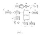
- FIG. 1 is a block diagram of a wireless terminal according to the present invention.
- a Radio Frequency (RF) module 123 performs a wireless communication function of the wireless terminal.
- the RF module 123 includes an RF transmitter for up-converting a frequency of a transmission signal and amplifying the up-converted transmission signal, and an RF receiver for low-noise-amplifying a received signal and down-converting a frequency of the low-noise-amplified signal.
- a modem 120 includes a transmitter for encoding and modulating the transmission signal and a receiver for demodulating and decoding the received signal.
- An audio processing unit 125 may include a codec, which includes a data codec for processing packet data and an audio codec for processing an audio signal such as a voice signal.
- the audio processing unit 125 converts a digital audio signal received from the modem 120 to an analog audio signal using the audio codec and reproduces the converted analog audio signal, and converts an analog audio signal generated by a microphone to a digital audio signal using the audio codec and transmits the converted digital audio signal to the modem 120.
- the codec may be included separately or in a controller 110.
- a memory 130 can include a program memory and a data memory.
- the program memory can store programs for controlling a general operation of the wireless terminal and programs for controlling the wireless terminal to be changed to a power-off state when a SIM card 170 is removed in a power-on state of the wireless terminal according to a preferred embodiment of the present invention.
- the data memory temporarily stores data generated while executing the programs.
- the controller 110 controls a general operation of the wireless terminal.
- the controller 110 may include the modem 120 and the codec.
- the controller 110 automatically changes the power state of the wireless terminal to the power-off state by controlling power control signals for controlling the power of the wireless terminal to be in the power-off state.
- the SIM card 170 includes a subscriber authentication module and can be inserted and removed into and from the wireless terminal. According to a preferred embodiment of the present invention, the SIM card 170 can be inserted and removed through an insertion part (not shown) disposed on the outer surface of the wireless terminal.
- a camera module 140 includes a camera sensor for capturing image data and converting a captured optical signal to an electrical signal and a signal processing unit for converting an analog image signal output from the camera sensor to digital data.
- the camera sensor is a Charge Coupled Device (CCD)
- the signal processing unit can be realized using a Digital Signal Processor (DSP).
- DSP Digital Signal Processor
- the camera sensor and the signal processing unit can be realized in one body or separately.
- An image processing unit 150 generates screen data to display the image signal output from the camera module 140.
- the image processing unit 150 processes the image signal output from the camera module 140 on a per-frame basis and outputs the processed frame image data according to characteristics of a display unit 160 and the size of a screen of the display unit 160.
- the image processing unit 150 including an image codec, encodes the frame image data to be displayed on the display unit 160 in a predetermined method and decodes the encoded frame image data to the original frame image data.
- the image codec can be a JPEG codec, an MPEG4 codec, or a Wavelet codec. It is assumed that the image processing unit 150 has an On-Screen Display (OSD) function, and the image processing unit 150 can output OSD data according to the size of the screen under the control of the controller 110.
- OSD On-Screen Display
- the display unit 160 displays the frame image data input from the image processing unit 150 and user data input from the controller 110 on the screen.
- the display unit 160 can be comprised of a Liquid Crystal Display (LCD), and in this case, the display unit 160 can include an LCD controller, a memory for storing image data, and an LCD display component. If the LCD is realized with a touch screen scheme, the display unit 160 can serve as an input unit. According to a preferred embodiment of the present invention, when the SIM card 170 is removed in the power-on state of the wireless terminal, the display unit 160 can display a message that power is turned off.
- a key-input unit 127 includes keys for inputting character and number information and function keys for setting various functions.
- FIG. 2 is a flowchart illustrating a process of controlling power when a SIM card is removed from a wireless terminal according to the present invention.
- step 201 power of the wireless terminal is turned on in step 201.
- the controller 110 determines in step 202 whether the SIM card 170 inserted through the insertion part disposed on the outer surface of the wireless terminal is removed.
- the controller 110 senses an error mode using an interrupt of a modem chip (not shown) and controls power control signals for controlling power of the wireless terminal to be changed to a power-off mode in step 203.
- the controller 110 controls the power of the wireless terminal to automatically change to a power-off state in step 204.
- the controller 110 can control the display unit 160 to display a message that the power of the wireless terminal is being turned off.
- FIG. 3 is a signal diagram illustrating states of power control signals for controlling power of a wireless terminal when the power control signals are changed to the power on/off mode according to the present invention.
- the power control signals for controlling the power of the wireless terminal include the power on/off control signal PS_HOLD(in), the key input power control signal KPDPWR_N(in), the battery control signal BAT_FET_N(out), the power supply control signal VREG outputs, and the reset control signal PON_RESET_N(out).
- the controller 110 controls the power control signals to be in an operating state of a period (A), and, as a result, the power of the wireless terminal is in the power-on state in a period (B).
- the period (B) corresponds to step 201 of FIG. 2 , indicating the power-on state of the wireless terminal.
- the controller 110 controls the key input power control signal KPDPWR_N(in) to definitely stay low until the power on/off control signal PS_HOLD(in) stays high.
- the controller 110 also controls the battery control signal BAT_FET_N(out) to be changed to low, controls MSMC, MSME, MSMP, MSMA, and TCXO, which are voltage types of the power supply control signal VREG outputs, to be sequentially turned on, and controls the reset control signal PON_RESET_N(out) to stay low for a predetermined time and then stay high.
- the power control signals are in the operating state of period (A) at the same time.
- the controller 110 controls the power control signals to be in an operating state of a period (C') in a period (C), and as a result, the power of the wireless terminal transitions to the power-off state in a period (D).
- Period (C') corresponds to step 203 of FIG. 2 , indicating an operation of changing to the power-off mode
- period (D) corresponds to step 204 of FIG. 2 , indicating an operation of turning off the power of the wireless terminal.
- the controller 110 controls the power on/off control signal PS_HOLD(in) to change to low and the key input power control signal KPDPWR_N(in) to change to high.
- the controller 110 also controls the battery control signal BAT_FET_N(out) to stay low, controls MSMC, MSME, MSMP, MSMA, and TCXO, which are the voltage types of the power supply control signal VREG outputs, to be sequentially turned off in reverse order, and controls the reset control signal PON_RESET_N(out) to stay low.
- the power control signals are in the operating state of period (C') at the same time.
- the power of the wireless terminal is controlled to turn off in period (D) by automatically changing the power control signals to the power-off mode as in period (C').
Landscapes
- Engineering & Computer Science (AREA)
- Computer Networks & Wireless Communication (AREA)
- Signal Processing (AREA)
- Physics & Mathematics (AREA)
- General Physics & Mathematics (AREA)
- Telephone Function (AREA)
- Mobile Radio Communication Systems (AREA)
Description
- The present invention relates generally to a power control method of a wireless terminal, and in particular, to a power control method of a wireless terminal to control power of the wireless terminal when a Subscriber Identity Module (SIM) card, which can be directly inserted/removed, is removed in a power-on state of the wireless terminal.
- In general, a Subscriber Identity Module (SIM) card is inserted in a rear side of a battery of a wireless terminal. To remove the SIM card from the wireless terminal, the battery must be first removed from the wireless terminal, and then the SIM card can be removed. Therefore, the wireless terminal from which the SIM card has been removed in a power-off state can be stabilized.
-
GB-A-2389279 - However, in a case of a wireless terminal using a SIM card which can be directly inserted / removed, the SIM card may be removed in a power-on state of the wireless terminal due to a mistake of a user. If the SIM card is removed in a power-on state of the wireless terminal, programs of the wireless terminal will often malfunction or become in an error or disorder state.
- The present invention is designed to substantially solve at least the above problems and/or disadvantages and to provide at least the advantages below. Accordingly, the object of the present invention is to provide a wireless terminal and a power control method to control power of the wireless terminal when a Subscriber Identity Module (SIM) card, which can be directly inserted/removed, is removed in a power-on state of the wireless terminal.
- This object is solved by the subject matter of the independent claims.
- Preferred embodiments are defined in the dependent claims.
- According to one aspect of the present invention, there is provided a method of controlling power in a wireless terminal having a Subscriber Identity Module (SIM) card which can be directly inserted/removed, including determining whether the SIM card is removed in a power-on state of the wireless terminal; and, if the SIM card is removed from the wireless terminal in the power-on state, a controller senses an error mode using an interrupt and controls power control signals for controlling power of the wireless terminal to be changed to a power-off state. In the method the power-off state of the wireless terminal may be achieved by changing power control signals for controlling the power of the wireless terminal to a power-off mode. In the method the power control signals of the wireless terminal may comprise a power on/off control signal, a key input power control signal, a battery control signal, a power supply control signal, and a reset control signal. According to another aspect of the present invention, there is provided a corresponding wireless terminal for carrying out the above method comprising a controller adapted for determining whether a SIM card is removed from the wireless terminal, adapted for sensing an error mode and adapted for controlling power control signals to change the wireless terminal from a power-on state to a power-off state.
- The present invention will become more apparent from the following detailed description when taken in conjunction with the accompanying drawing in which:
-
FIG. 1 is a block diagram of a wireless terminal according to the present invention; -
FIG. 2 is a flowchart illustrating a process of controlling power when a SIM card is removed from a wireless terminal according to the present invention; and -
FIG. 3 is a signal diagram illustrating states of power control signals for controlling power of a wireless terminal when the power control signals are changed to the power on/off mode according to the present invention. - Preferred embodiments of the present invention will be described herein below with reference to the accompanying drawings. In the drawings, the same or similar elements are denoted by the same reference numerals even though they are depicted in different drawings.
-
FIG. 1 is a block diagram of a wireless terminal according to the present invention. Referring toFIG. 1 , a Radio Frequency (RF)module 123 performs a wireless communication function of the wireless terminal. TheRF module 123 includes an RF transmitter for up-converting a frequency of a transmission signal and amplifying the up-converted transmission signal, and an RF receiver for low-noise-amplifying a received signal and down-converting a frequency of the low-noise-amplified signal. Amodem 120 includes a transmitter for encoding and modulating the transmission signal and a receiver for demodulating and decoding the received signal. Anaudio processing unit 125 may include a codec, which includes a data codec for processing packet data and an audio codec for processing an audio signal such as a voice signal. Theaudio processing unit 125 converts a digital audio signal received from themodem 120 to an analog audio signal using the audio codec and reproduces the converted analog audio signal, and converts an analog audio signal generated by a microphone to a digital audio signal using the audio codec and transmits the converted digital audio signal to themodem 120. Alternatively, the codec may be included separately or in acontroller 110.
Amemory 130 can include a program memory and a data memory. The program memory can store programs for controlling a general operation of the wireless terminal and programs for controlling the wireless terminal to be changed to a power-off state when aSIM card 170 is removed in a power-on state of the wireless terminal according to a preferred embodiment of the present invention. The data memory temporarily stores data generated while executing the programs. - The
controller 110 controls a general operation of the wireless terminal. In addition, thecontroller 110 may include themodem 120 and the codec. Furthermore, according to a preferred embodiment of the present invention, when theSIM card 170 is removed in the power-on state of the wireless terminal, thecontroller 110 automatically changes the power state of the wireless terminal to the power-off state by controlling power control signals for controlling the power of the wireless terminal to be in the power-off state. - The
SIM card 170 includes a subscriber authentication module and can be inserted and removed into and from the wireless terminal. According to a preferred embodiment of the present invention, theSIM card 170 can be inserted and removed through an insertion part (not shown) disposed on the outer surface of the wireless terminal. - A
camera module 140 includes a camera sensor for capturing image data and converting a captured optical signal to an electrical signal and a signal processing unit for converting an analog image signal output from the camera sensor to digital data. Herein, it is assumed that the camera sensor is a Charge Coupled Device (CCD), and the signal processing unit can be realized using a Digital Signal Processor (DSP). The camera sensor and the signal processing unit can be realized in one body or separately. - An
image processing unit 150 generates screen data to display the image signal output from thecamera module 140. Theimage processing unit 150 processes the image signal output from thecamera module 140 on a per-frame basis and outputs the processed frame image data according to characteristics of adisplay unit 160 and the size of a screen of thedisplay unit 160. Theimage processing unit 150, including an image codec, encodes the frame image data to be displayed on thedisplay unit 160 in a predetermined method and decodes the encoded frame image data to the original frame image data. Herein, the image codec can be a JPEG codec, an MPEG4 codec, or a Wavelet codec. It is assumed that theimage processing unit 150 has an On-Screen Display (OSD) function, and theimage processing unit 150 can output OSD data according to the size of the screen under the control of thecontroller 110. - The
display unit 160 displays the frame image data input from theimage processing unit 150 and user data input from thecontroller 110 on the screen. Thedisplay unit 160 can be comprised of a Liquid Crystal Display (LCD), and in this case, thedisplay unit 160 can include an LCD controller, a memory for storing image data, and an LCD display component. If the LCD is realized with a touch screen scheme, thedisplay unit 160 can serve as an input unit. According to a preferred embodiment of the present invention, when theSIM card 170 is removed in the power-on state of the wireless terminal, thedisplay unit 160 can display a message that power is turned off. A key-input unit 127 includes keys for inputting character and number information and function keys for setting various functions. - An operation of controlling power when the
SIM card 170 is removed from the wireless terminal will now be described in detail with reference toFIGs. 2 and3 .FIG. 2 is a flowchart illustrating a process of controlling power when a SIM card is removed from a wireless terminal according to the present invention. - Referring to
FIG. 2 , power of the wireless terminal is turned on instep 201. In the power-on state of the wireless terminal, thecontroller 110 determines instep 202 whether theSIM card 170 inserted through the insertion part disposed on the outer surface of the wireless terminal is removed. - If the
SIM card 170 is removed in the power-on state of the wireless terminal, thecontroller 110 senses an error mode using an interrupt of a modem chip (not shown) and controls power control signals for controlling power of the wireless terminal to be changed to a power-off mode instep 203. - By controlling the power control signals, i.e., a power on/off control signal PS_HOLD(in) (SEE
FIG. 3 ), a key input power control signal KPDPWR_N(in), a battery control signal BAT_FET_IN(out), a power supply control signal VREG outputs, and a reset control signal PON_RESET_N(out), to be changed to the power-off mode, thecontroller 110 controls the power of the wireless terminal to automatically change to a power-off state instep 204. - While performing an operation of changing the power control signals to the power-off mode in
step 203, thecontroller 110 can control thedisplay unit 160 to display a message that the power of the wireless terminal is being turned off. - An operation of changing the power of the wireless terminal to the power-off state by changing the power control signals to the power-off mode in
steps FIG. 3. FIG. 3 is a signal diagram illustrating states of power control signals for controlling power of a wireless terminal when the power control signals are changed to the power on/off mode according to the present invention. - Referring to
FIG. 3 , the power control signals for controlling the power of the wireless terminal include the power on/off control signal PS_HOLD(in), the key input power control signal KPDPWR_N(in), the battery control signal BAT_FET_N(out), the power supply control signal VREG outputs, and the reset control signal PON_RESET_N(out). - If a specific key for turning on the power of the wireless terminal is selected, the
controller 110 controls the power control signals to be in an operating state of a period (A), and, as a result, the power of the wireless terminal is in the power-on state in a period (B). The period (B) corresponds tostep 201 ofFIG. 2 , indicating the power-on state of the wireless terminal. - In period (A), the
controller 110 controls the key input power control signal KPDPWR_N(in) to definitely stay low until the power on/off control signal PS_HOLD(in) stays high. Thecontroller 110 also controls the battery control signal BAT_FET_N(out) to be changed to low, controls MSMC, MSME, MSMP, MSMA, and TCXO, which are voltage types of the power supply control signal VREG outputs, to be sequentially turned on, and controls the reset control signal PON_RESET_N(out) to stay low for a predetermined time and then stay high. The power control signals are in the operating state of period (A) at the same time. - Preferably, if the
SIM card 170 is removed in the power-on state of the wireless terminal as in the period (B), thecontroller 110 controls the power control signals to be in an operating state of a period (C') in a period (C), and as a result, the power of the wireless terminal transitions to the power-off state in a period (D). Period (C') corresponds to step 203 ofFIG. 2 , indicating an operation of changing to the power-off mode, and period (D) corresponds to step 204 ofFIG. 2 , indicating an operation of turning off the power of the wireless terminal. - In period (C'), the
controller 110 controls the power on/off control signal PS_HOLD(in) to change to low and the key input power control signal KPDPWR_N(in) to change to high. Thecontroller 110 also controls the battery control signal BAT_FET_N(out) to stay low, controls MSMC, MSME, MSMP, MSMA, and TCXO, which are the voltage types of the power supply control signal VREG outputs, to be sequentially turned off in reverse order, and controls the reset control signal PON_RESET_N(out) to stay low. The power control signals are in the operating state of period (C') at the same time. - As described above, in the present invention, if the
SIM card 170 is removed in the power-on state of the wireless terminal, the power of the wireless terminal is controlled to turn off in period (D) by automatically changing the power control signals to the power-off mode as in period (C'). - As described above, according to the present invention, by automatically changing power of a wireless terminal to a power-off state when a SIM card is removed in a power-on state of the wireless terminal, an abnormal system operation or a program error can be prevented, thereby stabilizing a system.
- While the invention has been shown and described with reference to a certain preferred embodiment thereof, it will be understood by those skilled in the art that various changes in form and details may be made therein without departing from the scope of the invention as defined by the appended claims.
Claims (4)
- A method of controlling power in a wireless terminal having a SIM card (170) which can be directly inserted/removed, the method comprising:determining whether the SIM card (170) is removed in a power-on state (B) of the wireless terminal; andif the SIM card (170) is removed from the wireless terminal in the power-on state (B), a controller (110) senses an error mode using an interrupt and controls power control signals for controlling power of the wireless terminal to be changed to a power-off state (D).
- The method of claim 1, wherein the power-off state (D) of the wireless terminal is achieved by changing power control signals for controlling the power of the wireless terminal to a power-off mode (C').
- The method of claim 2, wherein the power control signals of the wireless terminal comprise a power on/off control signal, a key input power control signal, a battery control signal, a power supply control signal, and a reset control signal.
- A wireless terminal for carrying out the method according to one of claims 1 to 3 comprising a controller adapted for determining whether a SIM card (170) is removed from the wireless terminal, adapted for sensing an error mode and adapted for controlling power control signals to change the wireless terminal from a power-on state (B) to a power-off state (D).
Priority Applications (1)
| Application Number | Priority Date | Filing Date | Title |
|---|---|---|---|
| EP15186283.6A EP2996253B1 (en) | 2006-02-21 | 2007-01-23 | Power control method of wireless terminal |
Applications Claiming Priority (1)
| Application Number | Priority Date | Filing Date | Title |
|---|---|---|---|
| KR1020060016707A KR100724864B1 (en) | 2006-02-21 | 2006-02-21 | Power control method of mobile terminal |
Related Child Applications (2)
| Application Number | Title | Priority Date | Filing Date |
|---|---|---|---|
| EP15186283.6A Division EP2996253B1 (en) | 2006-02-21 | 2007-01-23 | Power control method of wireless terminal |
| EP15186283.6A Division-Into EP2996253B1 (en) | 2006-02-21 | 2007-01-23 | Power control method of wireless terminal |
Publications (3)
| Publication Number | Publication Date |
|---|---|
| EP1821556A2 EP1821556A2 (en) | 2007-08-22 |
| EP1821556A3 EP1821556A3 (en) | 2011-09-21 |
| EP1821556B1 true EP1821556B1 (en) | 2015-10-28 |
Family
ID=38068950
Family Applications (2)
| Application Number | Title | Priority Date | Filing Date |
|---|---|---|---|
| EP07101022.7A Ceased EP1821556B1 (en) | 2006-02-21 | 2007-01-23 | Power control method of wireless terminal |
| EP15186283.6A Ceased EP2996253B1 (en) | 2006-02-21 | 2007-01-23 | Power control method of wireless terminal |
Family Applications After (1)
| Application Number | Title | Priority Date | Filing Date |
|---|---|---|---|
| EP15186283.6A Ceased EP2996253B1 (en) | 2006-02-21 | 2007-01-23 | Power control method of wireless terminal |
Country Status (4)
| Country | Link |
|---|---|
| US (1) | US20070218946A1 (en) |
| EP (2) | EP1821556B1 (en) |
| KR (1) | KR100724864B1 (en) |
| CN (1) | CN101026830A (en) |
Families Citing this family (7)
| Publication number | Priority date | Publication date | Assignee | Title |
|---|---|---|---|---|
| JP3742029B2 (en) * | 2002-04-15 | 2006-02-01 | 埼玉日本電気株式会社 | Mobile phone |
| JP4936998B2 (en) * | 2007-05-31 | 2012-05-23 | 富士通東芝モバイルコミュニケーションズ株式会社 | Mobile phone |
| DE102009018195A1 (en) * | 2009-04-22 | 2010-11-04 | Vodafone Holding Gmbh | Mobile device with multiple SIM cards |
| CN103582090A (en) * | 2012-08-07 | 2014-02-12 | 国基电子(上海)有限公司 | Router and power saving control method thereof |
| CN103856620B (en) * | 2012-12-06 | 2016-09-28 | 华为终端有限公司 | Control the method and device of terminal closedown |
| CN105867579A (en) * | 2015-12-14 | 2016-08-17 | 乐视移动智能信息技术(北京)有限公司 | Terminal control method and apparatus as well as terminal |
| KR102792334B1 (en) | 2019-09-03 | 2025-04-08 | 삼성전자주식회사 | Method for controlling power using socket and electronic device supporting the same |
Family Cites Families (6)
| Publication number | Priority date | Publication date | Assignee | Title |
|---|---|---|---|---|
| JP4194172B2 (en) * | 1998-05-18 | 2008-12-10 | キヤノン株式会社 | Image display device and inter-device communication method |
| GB9822697D0 (en) * | 1998-10-19 | 1998-12-09 | Nokia Mobile Phones Ltd | Data card holder |
| JP3424639B2 (en) * | 2000-02-22 | 2003-07-07 | 日本電気株式会社 | Electronic equipment and unique information management method |
| US7757094B2 (en) * | 2001-02-27 | 2010-07-13 | Qualcomm Incorporated | Power management for subscriber identity module |
| KR20030006713A (en) * | 2001-07-14 | 2003-01-23 | 기아자동차주식회사 | Reinforcement Structure in Automobile Front-Body |
| JP3742029B2 (en) * | 2002-04-15 | 2006-02-01 | 埼玉日本電気株式会社 | Mobile phone |
-
2006
- 2006-02-21 KR KR1020060016707A patent/KR100724864B1/en not_active Expired - Fee Related
-
2007
- 2007-01-17 CN CNA2007100019582A patent/CN101026830A/en active Pending
- 2007-01-23 EP EP07101022.7A patent/EP1821556B1/en not_active Ceased
- 2007-01-23 EP EP15186283.6A patent/EP2996253B1/en not_active Ceased
- 2007-02-21 US US11/709,350 patent/US20070218946A1/en not_active Abandoned
Also Published As
| Publication number | Publication date |
|---|---|
| EP1821556A2 (en) | 2007-08-22 |
| US20070218946A1 (en) | 2007-09-20 |
| EP2996253A1 (en) | 2016-03-16 |
| KR100724864B1 (en) | 2007-06-04 |
| EP1821556A3 (en) | 2011-09-21 |
| CN101026830A (en) | 2007-08-29 |
| EP2996253B1 (en) | 2017-08-02 |
Similar Documents
| Publication | Publication Date | Title |
|---|---|---|
| EP2533064B1 (en) | Apparatus and method for determining a remaining battery life of a portable terminal | |
| US8374648B2 (en) | Method for performing communication function in wireless terminal | |
| EP2996253B1 (en) | Power control method of wireless terminal | |
| KR20130024166A (en) | Device and method for performing call in wireless terminal | |
| US20130339719A1 (en) | Apparatus and method for controlling mode switch | |
| US10613959B2 (en) | Apparatus and method for controlling external device | |
| US8970792B2 (en) | Remote controller and remote controller set applied to display device | |
| KR20130040350A (en) | Device and method for controlling screen brightness in wireless terminal | |
| JP2005198309A (en) | Memory display device and method for portable terminal | |
| KR100605820B1 (en) | How to protect user data in PD phone equipped with PD function and phone function | |
| KR100678130B1 (en) | How to perform call on mobile terminal | |
| KR100452844B1 (en) | Portable terminal having power-saving function, and method for control thereof | |
| KR20130118090A (en) | Device and method for controlling power of external memory in wireless terminal | |
| KR100709601B1 (en) | SIM card selective synchronization method and mobile terminal using the same | |
| KR100594167B1 (en) | How to control your mobile device through external memory | |
| KR100678115B1 (en) | Starting method of mobile communication terminal | |
| KR100725185B1 (en) | How to save work contents of portable terminal | |
| KR100790070B1 (en) | Key input device and method of mobile terminal | |
| KR100630095B1 (en) | Operation control method according to low voltage of mobile terminal | |
| KR20060136235A (en) | Method for performing call in wireless terminal | |
| KR100687611B1 (en) | Method for providing power saving function in mobile communication terminal in sleep mode and mobile communication terminal | |
| KR20060130357A (en) | How to block call service of mobile terminal | |
| KR20080017639A (en) | Camera phone equipped with the USB interface unit in the camera module and its operation method | |
| KR20060076557A (en) | How to display memory capacity of mobile communication terminal | |
| KR20080042291A (en) | Terminal and Method for Provisional Wake-up Call |
Legal Events
| Date | Code | Title | Description |
|---|---|---|---|
| PUAI | Public reference made under article 153(3) epc to a published international application that has entered the european phase |
Free format text: ORIGINAL CODE: 0009012 |
|
| 17P | Request for examination filed |
Effective date: 20070123 |
|
| AK | Designated contracting states |
Kind code of ref document: A2 Designated state(s): AT BE BG CH CY CZ DE DK EE ES FI FR GB GR HU IE IS IT LI LT LU LV MC NL PL PT RO SE SI SK TR |
|
| AX | Request for extension of the european patent |
Extension state: AL BA HR MK YU |
|
| PUAL | Search report despatched |
Free format text: ORIGINAL CODE: 0009013 |
|
| AK | Designated contracting states |
Kind code of ref document: A3 Designated state(s): AT BE BG CH CY CZ DE DK EE ES FI FR GB GR HU IE IS IT LI LT LU LV MC NL PL PT RO SE SI SK TR |
|
| AX | Request for extension of the european patent |
Extension state: AL BA HR MK RS |
|
| AKX | Designation fees paid |
Designated state(s): DE FR GB |
|
| 17Q | First examination report despatched |
Effective date: 20120521 |
|
| RAP1 | Party data changed (applicant data changed or rights of an application transferred) |
Owner name: SAMSUNG ELECTRONICS CO., LTD. |
|
| REG | Reference to a national code |
Ref country code: DE Ref legal event code: R079 Ref document number: 602007043650 Country of ref document: DE Free format text: PREVIOUS MAIN CLASS: H04Q0007320000 Ipc: H04B0001400000 |
|
| GRAP | Despatch of communication of intention to grant a patent |
Free format text: ORIGINAL CODE: EPIDOSNIGR1 |
|
| RIC1 | Information provided on ipc code assigned before grant |
Ipc: H04B 1/40 20150101AFI20150401BHEP Ipc: H04W 52/02 20090101ALI20150401BHEP Ipc: H04B 1/401 20150101ALI20150401BHEP |
|
| INTG | Intention to grant announced |
Effective date: 20150504 |
|
| GRAS | Grant fee paid |
Free format text: ORIGINAL CODE: EPIDOSNIGR3 |
|
| GRAA | (expected) grant |
Free format text: ORIGINAL CODE: 0009210 |
|
| AK | Designated contracting states |
Kind code of ref document: B1 Designated state(s): DE FR GB |
|
| REG | Reference to a national code |
Ref country code: GB Ref legal event code: FG4D |
|
| REG | Reference to a national code |
Ref country code: DE Ref legal event code: R096 Ref document number: 602007043650 Country of ref document: DE |
|
| REG | Reference to a national code |
Ref country code: FR Ref legal event code: PLFP Year of fee payment: 10 |
|
| REG | Reference to a national code |
Ref country code: DE Ref legal event code: R097 Ref document number: 602007043650 Country of ref document: DE |
|
| PLBE | No opposition filed within time limit |
Free format text: ORIGINAL CODE: 0009261 |
|
| STAA | Information on the status of an ep patent application or granted ep patent |
Free format text: STATUS: NO OPPOSITION FILED WITHIN TIME LIMIT |
|
| 26N | No opposition filed |
Effective date: 20160729 |
|
| REG | Reference to a national code |
Ref country code: FR Ref legal event code: PLFP Year of fee payment: 11 |
|
| REG | Reference to a national code |
Ref country code: FR Ref legal event code: PLFP Year of fee payment: 12 |
|
| PGFP | Annual fee paid to national office [announced via postgrant information from national office to epo] |
Ref country code: FR Payment date: 20181224 Year of fee payment: 13 Ref country code: GB Payment date: 20181220 Year of fee payment: 13 |
|
| PGFP | Annual fee paid to national office [announced via postgrant information from national office to epo] |
Ref country code: DE Payment date: 20181219 Year of fee payment: 13 |
|
| REG | Reference to a national code |
Ref country code: DE Ref legal event code: R119 Ref document number: 602007043650 Country of ref document: DE |
|
| GBPC | Gb: european patent ceased through non-payment of renewal fee |
Effective date: 20200123 |
|
| PG25 | Lapsed in a contracting state [announced via postgrant information from national office to epo] |
Ref country code: DE Free format text: LAPSE BECAUSE OF NON-PAYMENT OF DUE FEES Effective date: 20200801 Ref country code: FR Free format text: LAPSE BECAUSE OF NON-PAYMENT OF DUE FEES Effective date: 20200131 Ref country code: GB Free format text: LAPSE BECAUSE OF NON-PAYMENT OF DUE FEES Effective date: 20200123 |