EP1821364A1 - Easily maintainable on-vehicle electronic device - Google Patents
Easily maintainable on-vehicle electronic device Download PDFInfo
- Publication number
- EP1821364A1 EP1821364A1 EP07002929A EP07002929A EP1821364A1 EP 1821364 A1 EP1821364 A1 EP 1821364A1 EP 07002929 A EP07002929 A EP 07002929A EP 07002929 A EP07002929 A EP 07002929A EP 1821364 A1 EP1821364 A1 EP 1821364A1
- Authority
- EP
- European Patent Office
- Prior art keywords
- circuit board
- circuit
- electronic device
- terminal members
- attachment
- Prior art date
- Legal status (The legal status is an assumption and is not a legal conclusion. Google has not performed a legal analysis and makes no representation as to the accuracy of the status listed.)
- Granted
Links
- 239000011521 glass Substances 0.000 claims abstract description 31
- 239000004020 conductor Substances 0.000 claims abstract description 25
- 239000002184 metal Substances 0.000 claims description 9
- 238000000465 moulding Methods 0.000 claims description 4
- 229920003002 synthetic resin Polymers 0.000 claims description 3
- 239000000057 synthetic resin Substances 0.000 claims description 3
- 238000012423 maintenance Methods 0.000 description 4
- 238000005476 soldering Methods 0.000 description 3
- 238000007796 conventional method Methods 0.000 description 2
- 239000000428 dust Substances 0.000 description 2
- XLYOFNOQVPJJNP-UHFFFAOYSA-N water Substances O XLYOFNOQVPJJNP-UHFFFAOYSA-N 0.000 description 2
- 230000003321 amplification Effects 0.000 description 1
- 238000009434 installation Methods 0.000 description 1
- WABPQHHGFIMREM-UHFFFAOYSA-N lead(0) Chemical compound [Pb] WABPQHHGFIMREM-UHFFFAOYSA-N 0.000 description 1
- 238000000034 method Methods 0.000 description 1
- 238000003199 nucleic acid amplification method Methods 0.000 description 1
- 230000008929 regeneration Effects 0.000 description 1
- 238000011069 regeneration method Methods 0.000 description 1
- 230000035945 sensitivity Effects 0.000 description 1
- 229910000679 solder Inorganic materials 0.000 description 1
Images


Classifications
-
- H—ELECTRICITY
- H01—ELECTRIC ELEMENTS
- H01Q—ANTENNAS, i.e. RADIO AERIALS
- H01Q1/00—Details of, or arrangements associated with, antennas
- H01Q1/12—Supports; Mounting means
- H01Q1/1271—Supports; Mounting means for mounting on windscreens
-
- H—ELECTRICITY
- H01—ELECTRIC ELEMENTS
- H01Q—ANTENNAS, i.e. RADIO AERIALS
- H01Q1/00—Details of, or arrangements associated with, antennas
- H01Q1/27—Adaptation for use in or on movable bodies
- H01Q1/32—Adaptation for use in or on road or rail vehicles
- H01Q1/325—Adaptation for use in or on road or rail vehicles characterised by the location of the antenna on the vehicle
- H01Q1/3283—Adaptation for use in or on road or rail vehicles characterised by the location of the antenna on the vehicle side-mounted antennas, e.g. bumper-mounted, door-mounted
-
- H—ELECTRICITY
- H01—ELECTRIC ELEMENTS
- H01Q—ANTENNAS, i.e. RADIO AERIALS
- H01Q23/00—Antennas with active circuits or circuit elements integrated within them or attached to them
Definitions
- the present invention relates to an on-vehicle electronic device including an antenna circuit such as a preamplifier circuit and interposed between an antenna radiating conductor provided on a glass surface of a vehicle window and an external circuit such as a receiver circuit, and particularly to an on-vehicle electronic device used attached to the glass surface.
- an antenna circuit such as a preamplifier circuit and interposed between an antenna radiating conductor provided on a glass surface of a vehicle window and an external circuit such as a receiver circuit, and particularly to an on-vehicle electronic device used attached to the glass surface.
- a signal received by the antenna radiating conductor needs to be promptly amplified so that the attenuation of the received signal is suppressed as much as possible to thereby obtain good reception sensitivity.
- an electronic device including therein a circuit board provided with a preamplifier circuit is usually attached to the same glass surface in the vicinity of the antenna radiating conductor so that the signal wave is sent to an external circuit such as a receiver circuit via the preamplifier circuit (see Pages 2 and 3 and Fig. 1 of Japanese Unexamined Patent Application Publication No. 5-327329 , for example).
- the circuit board included therein is electrically connected to a pair of feed portions of the antenna radiating conductor via a lead wire or the like, and is fixed to the glass surface of the vehicle window via attachment leg pieces or the like.
- the connection of the electronic device to the antenna radiating conductor or the glass surface is generally made by soldering.
- the electronic device which includes therein the circuit board provided with the preamplifier circuit or the like and is attached to the glass surface of the vehicle window in the vicinity of the antenna radiating conductor, is connected to the antenna radiating conductor or the glass surface by soldering or the like to thereby secure required attachment strength.
- the electronic device has such an attachment structure that makes it extremely difficult to detach and reattach the circuit board with respect to the glass surface. Therefore, maintenance such as adjustment, repair, or component replacement of the antenna circuit including the preamplifier circuit cannot be easily performed.
- the present invention has been made in view of the above-described circumference of the conventional technique, and an object of the present invention is to provide an easily maintainable on-vehicle electronic device, in which a circuit board can be attached and detached without difficulty with respect to a glass surface of a vehicle window.
- an on-vehicle electronic device includes a circuit board, an attachment base, and a plurality of attachment screws.
- the circuit board includes an antenna circuit, and a feeding electrode and an earth electrode drawn from the antenna circuit.
- the attachment base includes a pair of terminal members held by an insulative member, and is fixed to a glass surface of a vehicle window.
- the plurality of attachment screws attachably and detachably fix the circuit board to the attachment base.
- the circuit board is fixed to the attachment base, with the pair of the terminal members connected to a pair of feed portions of an antenna radiating conductor fixedly provided to the glass surface, and with the feeding electrode pressure-contacted with one of the two terminal members and the earth electrode pressure-contacted with the other one of the two terminal members.
- the feeding electrode and the earth electrode of the circuit board can be pressure-contacted with the terminal members of the attachment base through the fastening of the attachment screws.
- the antenna circuit provided on the circuit board and the feed portions of the antenna radiating conductor are electrically connected to each other via the terminal members.
- the circuit board can be easily detached from the attachment base by releasing the fastening of the attachment screws, while required attachment strength can be secured by fastening the attachment screws when attaching the circuit board again to the attachment base. Therefore, maintenance such as adjustment, repair, or component replacement of the antenna circuit can be easily performed.
- soldering or the like can be employed to connect the terminal members to the feed portions of the antenna radiating conductor. Accordingly, there is no possibility of insufficient attachment strength of the electronic device with respect to the glass surface of the vehicle window.
- the circuit board may be formed with the feeding electrode and the earth electrode on a surface thereof, and may include a pair of through holes, which face the vicinities of the feeding electrode and the earth electrode, respectively, and through which the attachment screws are inserted.
- each of the terminal members may include a board mounting portion pressure-contacted with either one of the feeding electrode and the earth electrode and formed with a screw hole into which the corresponding attachment screw is screwed.
- an attachment structure can be adopted without difficulty in which, even if the attachment screws are inserted through the through holes and screwed deep into the screw holes of the board mounting portions after portions of the circuit board in the vicinities of the through holes have been mounted on the board mounting portions of the terminal members, the leading ends of the attachment screws will not reach the glass surface. Therefore, this configuration is preferable in that it is easy to perform an attachment operation of making the circuit board pressure-contacted with and fixed to the terminal members by using the attachment screws, and to increase the attachment strength of the circuit board with respect to the terminal members.
- each of the terminal members may be formed by a metal plate, which is bent between the board mounting portion and a fixed portion connected to the corresponding feed portion, and a part of the metal plate may be buried in the insulative member through insert molding.
- This configuration is preferable in that the attachment base can be easily and highly accurately manufactured.
- the antenna circuit provided on the circuit board may include a preamplifier circuit.
- a shield case may be provided which is formed by a metal plate and attached to the circuit board to cover the preamplifier circuit.
- one end of a coaxial cable held by the shield case may be connected to a wiring pattern of the circuit board to establish conduction between the preamplifier circuit and an external circuit.
- the shield case can protect the preamplifier circuit by electromagnetically shielding the circuit against an external wave, and thus that noise of the received signal can be reduced.
- a radome may be provided which is formed of a synthetic resin and attached to the attachment base to cover the circuit board and the shield case. This configuration is preferable in that the water resistance and dust resistance performance and the designability can be improved by the radome.
- the circuit board can be attached and detached by the attachment screws with respect to the attachment base fixed to the glass surface of the vehicle window. Further, the circuit board can be easily detached from the attachment base by releasing the fastening of the attachment screws, while required attachment strength can be secured by fastening the attachment screws when attaching the circuit board again to the attachment base. Accordingly, maintenance such as adjustment, repair, or component replacement of the antenna circuit can be easily performed.
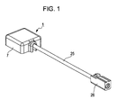
- An on-vehicle electronic device 1 illustrated in the drawings is for amplifying an external signal received by an antenna radiating conductor 21, which is fixedly provided to a glass surface 20 (see Fig. 4) of a vehicle window, and for sending the amplified signal to a receiver circuit (not illustrated), and is used attached to the glass surface 20.
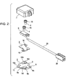
- the on-vehicle electronic device 1 mainly includes an attachment base 2, a circuit board (an LNA (low noise amplifier) board) 3, attachment screws 4 and 5, a shield case 6, and a radome 7.
- a wiring pattern of an antenna circuit (not illustrated) provided on the circuit board 3 is connected to one end (i.e., an input end) of a coaxial cable 25 held by the shield case 6, and the other end (i.e., an output end) of the coaxial cable 25 is attached with a coaxial connector 26.
- the antenna radiating conductor 21 is a loop antenna patterned on the glass surface 20, and the opposite ends of the loop form feed portions 21a and 21b.
- the attachment base 2 is formed by integrating an insulative member 8 with conductive terminal members 9 and 10 through insert molding.
- the insulative member 8 is molded into a substantially cross shape in a plan view. With the center of the insulative member 8 as a base, a pair of the terminal members 9 and 10 are disposed to be substantially point-symmetrical to each other. As illustrated in Fig.
- the terminal member 9 is a metal plate bent by press processing, and includes a flat fixed portion 9a solder-joined (the reference numeral 22 denotes a solder) to the feed portion 21a of the antenna radiating conductor 21, a flat board mounting portion 9b extending at a position apart from the glass surface 20 and pressure-contacted with a feeding electrode 11 of the circuit board 3, and a standing portion 9c which is an intermediate portion connecting the fixed portion 9a to the board mounting portion 9b and buried in the insulative member 8.
- the board mounting portion 9b is formed with a screw hole 9d into which the attachment screw 4 is screwed.
- the terminal member 10 is a metal plate bent into the same shape as the shape of the terminal member 9, and includes a flat fixed portion 10a solder-joined to the feed portion 21b of the antenna radiating conductor 21, a flat board mounting portion 10b extending at a position apart from the glass surface 20 and pressure-contacted with an earth electrode 12 of the circuit board 3, and a standing portion 10c which is an intermediate portion connecting the fixed portion 10a to the board mounting portion 10b and buried in the insulative member 8.
- the board mounting portion 10b is formed with a screw hole 10d into which the attachment screw 5 is screwed. Since the terminal members 9 and 10 are integrated with the insulative member 8 through insert molding, the attachment base 2 can be easily and highly accurately manufactured.
- the upper surface of the circuit board 3 is provided with the antenna circuit (not illustrated) including a preamplifier circuit, and the lower surface of the circuit board 3 is formed with the feeding electrode 11 and the earth electrode 12 drawn from the antenna circuit. That is, the antenna circuit on the upper surface and the respective electrodes 11 and 12 on the lower surface are connected to each other via wall conductors of through holes 13 and 14 formed in two corners of the circuit board 3. The peripheries of the through holes 13 and 14 on the lower surface are the regions in which the feeding electrode 11 and the earth electrode 12 are respectively formed.
- the circuit board 3 is mounted on the attachment base 2, with the through holes 13 and 14 positioned directly on the screw holes 9d and 10d, respectively.
- the circuit board 3 With leading end portions of the attachment screws 4 and 5 inserted through the through holes 13 and 14 and screwed into the screw holes 9d and 10d, the circuit board 3 is nipped and fixed between washers 15 and 16 of the attachment screws 4 and 5 and the board mounting portions 9b and 10b of the terminal members 9 and 10. That is, the circuit board 3 is fixed to the attachment base 2 through the fastening of the attachment screws 4 and 5, with the feeding electrode 11 and the earth electrode 12 pressure-contacted with the board mounting portions 9b and 10b, respectively. If the fastening of the attachment screws 4 and 5 with respect to the terminal members 9 and 10 is released, the circuit board 3 can be detached from the attachment base 2.
- the shield case 6 includes a box-shaped member formed by a metal plate, and is attached to the circuit board 3 to cover the preamplifier circuit.
- the shield case 6 is for protecting the preamplifier circuit by electromagnetically shielding the circuit against an external wave. Thereby, noise of the received signal can be reduced.
- the radome 7 is a chassis formed of a synthetic resin, and snap hooks (not illustrated) provided at a lower portion thereof are snapped in locking grooves 8a of the insulative member 8.
- the radome 7 is attached to the attachment base 2 to cover the circuit board 3, the shield case 6, the attachment screws 4 and 5, and the like. The water resistance and dust resistance performance and the designability can be improved by the radome 7.
- the terminal members 9 and 10 are solder-joined to the feed portions 21a and 21b of the antenna radiating conductor 21.
- the attachment base 2 is firmly fixed to the glass surface 20 of the vehicle window.
- the feeding electrode 11 and the earth electrode 12 of the circuit board 3, which are screwed into and fixed to the attachment base 2 are pressure-contacted with the terminal members 9 and 10.
- the external signal received by the antenna radiating conductor 21 patterned on the glass surface 20 is promptly sent from the feed portions 21a and 21b to the antenna circuit of the circuit board 3 to be subjected to amplification processing, and the amplified signal is sent to the external receiver circuit via the coaxial cable 25. Accordingly, it is possible to suppress the attenuation of the received signal, and thus to perform effective regeneration of the signal.
- the circuit board 3 can be attached and detached by the attachment screws 4 and 5 with respect to the attachment base 2 fixed to the glass surface 20 of the vehicle window. Further, the feeding electrode 11 and the earth electrode 12 can be pressure-contacted with the terminal members 9 and 10 through the fastening of the attachment screws 4 and 5. Therefore, electrical connection of the antenna circuit provided on the circuit board 3 to the feed portions 21a and 21b of the antenna radiating conductor 21 can be easily and reliably performed. Further, since the terminal members 9 and 10 are solder-joined to the feed portions 21a and 21b, there is no possibility of insufficient attachment strength of the on-vehicle electronic device 1 with respect to the glass surface 20.
- the circuit board 3 can be easily detached from the attachment base 2 by releasing the fastening of the attachment screws 4 and 5, while the required attachment strength can be secured by fastening the attachment screws 4 and 5 when attaching the circuit board 3 again to the attachment base 2. Accordingly, there is an advantage in that maintenance such as adjustment, repair, or component replacement of the antenna circuit can be easily performed.
- the board mounting portions 9b and 10b of the terminal members 9 and 10 extend at the respective positions apart from the glass surface 20. Further, the attachment screws 4 and 5 are fastened to the board mounting portions 9b and 10b, respectively, so that the board mounting portions 9b and 10b are pressure-contacted with the feeding electrode 11 and the earth electrode 12. Therefore, even if the attachment screws 4 and 5 are inserted through the through holes 13 and 14 and screwed deep into the screw holes 9d and 10d after the corners of the circuit board 3 have been mounted on the board mounting portions 9b and 10b, the leading ends of the attachment screws 4 and 5 will not reach the glass surface 20. Accordingly, it is easy to perform an attachment operation of making the circuit board 3 pressure-contacted with and fixed to the terminal members 9 and 10 by using the attachment screws 4 and 5, and to increase the attachment strength of the circuit board 3 with respect to the terminal members 9 and 10.
Landscapes
- Engineering & Computer Science (AREA)
- Remote Sensing (AREA)
- Details Of Aerials (AREA)
- Support Of Aerials (AREA)
Abstract
Description
- The present invention relates to an on-vehicle electronic device including an antenna circuit such as a preamplifier circuit and interposed between an antenna radiating conductor provided on a glass surface of a vehicle window and an external circuit such as a receiver circuit, and particularly to an on-vehicle electronic device used attached to the glass surface.
- Conventionally, there has been widely known a method of providing a glass surface of a vehicle window (e.g., a rear window) with a relatively long antenna radiating conductor such as a diversity antenna. Such an antenna device using the vehicle window as the installation space therefor is expected to be increasingly generalized along with the spread of terrestrial digital broadcasting.
- As for the signal wave of the terrestrial digital broadcasting or the like, a signal received by the antenna radiating conductor needs to be promptly amplified so that the attenuation of the received signal is suppressed as much as possible to thereby obtain good reception sensitivity. In the antenna device including the antenna radiating conductor disposed on the glass surface of the vehicle window, therefore, an electronic device including therein a circuit board provided with a preamplifier circuit is usually attached to the same glass surface in the vicinity of the antenna radiating conductor so that the signal wave is sent to an external circuit such as a receiver circuit via the preamplifier circuit (see
Pages Japanese Unexamined Patent Application Publication No. 5-327329 - As in the above-described conventional technique, the electronic device, which includes therein the circuit board provided with the preamplifier circuit or the like and is attached to the glass surface of the vehicle window in the vicinity of the antenna radiating conductor, is connected to the antenna radiating conductor or the glass surface by soldering or the like to thereby secure required attachment strength. However, the electronic device has such an attachment structure that makes it extremely difficult to detach and reattach the circuit board with respect to the glass surface. Therefore, maintenance such as adjustment, repair, or component replacement of the antenna circuit including the preamplifier circuit cannot be easily performed.
- The present invention has been made in view of the above-described circumference of the conventional technique, and an object of the present invention is to provide an easily maintainable on-vehicle electronic device, in which a circuit board can be attached and detached without difficulty with respect to a glass surface of a vehicle window.
- To achieve the above object, an on-vehicle electronic device according to the present invention includes a circuit board, an attachment base, and a plurality of attachment screws. The circuit board includes an antenna circuit, and a feeding electrode and an earth electrode drawn from the antenna circuit. The attachment base includes a pair of terminal members held by an insulative member, and is fixed to a glass surface of a vehicle window. The plurality of attachment screws attachably and detachably fix the circuit board to the attachment base. The circuit board is fixed to the attachment base, with the pair of the terminal members connected to a pair of feed portions of an antenna radiating conductor fixedly provided to the glass surface, and with the feeding electrode pressure-contacted with one of the two terminal members and the earth electrode pressure-contacted with the other one of the two terminal members.
- According to the on-vehicle electronic device, in which the circuit board is thus made attachable and detachable by the attachment screws with respect to the attachment base fixed to the glass surface of the vehicle window, the feeding electrode and the earth electrode of the circuit board can be pressure-contacted with the terminal members of the attachment base through the fastening of the attachment screws. Thus, the antenna circuit provided on the circuit board and the feed portions of the antenna radiating conductor are electrically connected to each other via the terminal members. Further, the circuit board can be easily detached from the attachment base by releasing the fastening of the attachment screws, while required attachment strength can be secured by fastening the attachment screws when attaching the circuit board again to the attachment base. Therefore, maintenance such as adjustment, repair, or component replacement of the antenna circuit can be easily performed. Further, soldering or the like can be employed to connect the terminal members to the feed portions of the antenna radiating conductor. Accordingly, there is no possibility of insufficient attachment strength of the electronic device with respect to the glass surface of the vehicle window.
- In the above-described configuration, the circuit board may be formed with the feeding electrode and the earth electrode on a surface thereof, and may include a pair of through holes, which face the vicinities of the feeding electrode and the earth electrode, respectively, and through which the attachment screws are inserted. Further, each of the terminal members may include a board mounting portion pressure-contacted with either one of the feeding electrode and the earth electrode and formed with a screw hole into which the corresponding attachment screw is screwed. Thus configured, an attachment structure can be adopted without difficulty in which, even if the attachment screws are inserted through the through holes and screwed deep into the screw holes of the board mounting portions after portions of the circuit board in the vicinities of the through holes have been mounted on the board mounting portions of the terminal members, the leading ends of the attachment screws will not reach the glass surface. Therefore, this configuration is preferable in that it is easy to perform an attachment operation of making the circuit board pressure-contacted with and fixed to the terminal members by using the attachment screws, and to increase the attachment strength of the circuit board with respect to the terminal members. In this case, each of the terminal members may be formed by a metal plate, which is bent between the board mounting portion and a fixed portion connected to the corresponding feed portion, and a part of the metal plate may be buried in the insulative member through insert molding. This configuration is preferable in that the attachment base can be easily and highly accurately manufactured.
- Further, in the above-described configuration, the antenna circuit provided on the circuit board may include a preamplifier circuit. This configuration is preferable in that a signal received by the antenna radiating conductor can be promptly amplified, and thus that the attenuation of the received signal can be suppressed. In this case, a shield case may be provided which is formed by a metal plate and attached to the circuit board to cover the preamplifier circuit. Further, one end of a coaxial cable held by the shield case may be connected to a wiring pattern of the circuit board to establish conduction between the preamplifier circuit and an external circuit. This configuration is preferable in that the shield case can protect the preamplifier circuit by electromagnetically shielding the circuit against an external wave, and thus that noise of the received signal can be reduced. In addition, a radome may be provided which is formed of a synthetic resin and attached to the attachment base to cover the circuit board and the shield case. This configuration is preferable in that the water resistance and dust resistance performance and the designability can be improved by the radome.
- In the on-vehicle electronic device according to the present invention, the circuit board can be attached and detached by the attachment screws with respect to the attachment base fixed to the glass surface of the vehicle window. Further, the circuit board can be easily detached from the attachment base by releasing the fastening of the attachment screws, while required attachment strength can be secured by fastening the attachment screws when attaching the circuit board again to the attachment base. Accordingly, maintenance such as adjustment, repair, or component replacement of the antenna circuit can be easily performed.
-
- Fig. 1 is an external view of an on-vehicle electronic device according to an embodiment of the present invention;
- Fig. 2 is an exploded perspective view of the on-vehicle electronic device;
- Fig. 3 is a plan view illustrating a connection structure of the on-vehicle electronic device and an antenna radiating conductor;
- Fig. 4 is a cross-sectional view along the IV-IV line shown in Fig. 3; and
- Fig. 5 is an exploded perspective view corresponding to Fig. 3.
- An embodiment of the present invention will now be described with reference to the drawings.
- An on-vehicle
electronic device 1 illustrated in the drawings is for amplifying an external signal received by anantenna radiating conductor 21, which is fixedly provided to a glass surface 20 (see Fig. 4) of a vehicle window, and for sending the amplified signal to a receiver circuit (not illustrated), and is used attached to theglass surface 20. As illustrated in Fig. 2, the on-vehicleelectronic device 1 mainly includes anattachment base 2, a circuit board (an LNA (low noise amplifier) board) 3,attachment screws shield case 6, and aradome 7. Further, a wiring pattern of an antenna circuit (not illustrated) provided on thecircuit board 3 is connected to one end (i.e., an input end) of acoaxial cable 25 held by theshield case 6, and the other end (i.e., an output end) of thecoaxial cable 25 is attached with acoaxial connector 26. Theantenna radiating conductor 21 is a loop antenna patterned on theglass surface 20, and the opposite ends of the loopform feed portions - The configuration of the on-vehicle
electronic device 1 will now be described in detail. Theattachment base 2 is formed by integrating aninsulative member 8 withconductive terminal members insulative member 8 is molded into a substantially cross shape in a plan view. With the center of theinsulative member 8 as a base, a pair of theterminal members terminal member 9 is a metal plate bent by press processing, and includes a flat fixedportion 9a solder-joined (thereference numeral 22 denotes a solder) to thefeed portion 21a of theantenna radiating conductor 21, a flatboard mounting portion 9b extending at a position apart from theglass surface 20 and pressure-contacted with afeeding electrode 11 of thecircuit board 3, and a standingportion 9c which is an intermediate portion connecting thefixed portion 9a to theboard mounting portion 9b and buried in theinsulative member 8. Theboard mounting portion 9b is formed with ascrew hole 9d into which theattachment screw 4 is screwed. Theterminal member 10 is a metal plate bent into the same shape as the shape of theterminal member 9, and includes a flat fixedportion 10a solder-joined to thefeed portion 21b of theantenna radiating conductor 21, a flatboard mounting portion 10b extending at a position apart from theglass surface 20 and pressure-contacted with anearth electrode 12 of thecircuit board 3, and a standingportion 10c which is an intermediate portion connecting thefixed portion 10a to theboard mounting portion 10b and buried in theinsulative member 8. Theboard mounting portion 10b is formed with ascrew hole 10d into which theattachment screw 5 is screwed. Since theterminal members insulative member 8 through insert molding, theattachment base 2 can be easily and highly accurately manufactured. - The upper surface of the
circuit board 3 is provided with the antenna circuit (not illustrated) including a preamplifier circuit, and the lower surface of thecircuit board 3 is formed with thefeeding electrode 11 and theearth electrode 12 drawn from the antenna circuit. That is, the antenna circuit on the upper surface and therespective electrodes holes circuit board 3. The peripheries of the throughholes electrode 11 and theearth electrode 12 are respectively formed. Thecircuit board 3 is mounted on theattachment base 2, with the throughholes holes circuit board 3 is nipped and fixed betweenwashers board mounting portions terminal members circuit board 3 is fixed to theattachment base 2 through the fastening of the attachment screws 4 and 5, with the feedingelectrode 11 and theearth electrode 12 pressure-contacted with theboard mounting portions terminal members circuit board 3 can be detached from theattachment base 2. - As illustrated in Fig. 5, the
shield case 6 includes a box-shaped member formed by a metal plate, and is attached to thecircuit board 3 to cover the preamplifier circuit. Theshield case 6 is for protecting the preamplifier circuit by electromagnetically shielding the circuit against an external wave. Thereby, noise of the received signal can be reduced. Meanwhile, theradome 7 is a chassis formed of a synthetic resin, and snap hooks (not illustrated) provided at a lower portion thereof are snapped in lockinggrooves 8a of theinsulative member 8. Theradome 7 is attached to theattachment base 2 to cover thecircuit board 3, theshield case 6, the attachment screws 4 and 5, and the like. The water resistance and dust resistance performance and the designability can be improved by theradome 7. - In the thus configured on-vehicle
electronic device 1, theterminal members feed portions antenna radiating conductor 21. Thus, theattachment base 2 is firmly fixed to theglass surface 20 of the vehicle window. Further, the feedingelectrode 11 and theearth electrode 12 of thecircuit board 3, which are screwed into and fixed to theattachment base 2, are pressure-contacted with theterminal members antenna radiating conductor 21 patterned on theglass surface 20 is promptly sent from thefeed portions circuit board 3 to be subjected to amplification processing, and the amplified signal is sent to the external receiver circuit via thecoaxial cable 25. Accordingly, it is possible to suppress the attenuation of the received signal, and thus to perform effective regeneration of the signal. - As described above, in the on-vehicle
electronic device 1 according to the present embodiment, thecircuit board 3 can be attached and detached by the attachment screws 4 and 5 with respect to theattachment base 2 fixed to theglass surface 20 of the vehicle window. Further, the feedingelectrode 11 and theearth electrode 12 can be pressure-contacted with theterminal members circuit board 3 to thefeed portions antenna radiating conductor 21 can be easily and reliably performed. Further, since theterminal members feed portions electronic device 1 with respect to theglass surface 20. Furthermore, thecircuit board 3 can be easily detached from theattachment base 2 by releasing the fastening of the attachment screws 4 and 5, while the required attachment strength can be secured by fastening the attachment screws 4 and 5 when attaching thecircuit board 3 again to theattachment base 2. Accordingly, there is an advantage in that maintenance such as adjustment, repair, or component replacement of the antenna circuit can be easily performed. - Furthermore, in the present on-vehicle
electronic device 1, theboard mounting portions terminal members glass surface 20. Further, the attachment screws 4 and 5 are fastened to theboard mounting portions board mounting portions electrode 11 and theearth electrode 12. Therefore, even if the attachment screws 4 and 5 are inserted through the throughholes circuit board 3 have been mounted on theboard mounting portions glass surface 20. Accordingly, it is easy to perform an attachment operation of making thecircuit board 3 pressure-contacted with and fixed to theterminal members circuit board 3 with respect to theterminal members
Claims (6)
- An on-vehicle electronic device comprising:a circuit board including an antenna circuit, and a feeding electrode and an earth electrode drawn from the antenna circuit;an attachment base including a pair of terminal members held by an insulative member, and fixed to a glass surface of a vehicle window; anda plurality of attachment screws for attachably and detachably fixing the circuit board to the attachment base,wherein the circuit board is fixed to the attachment base, with the pair of the terminal members connected to a pair of feed portions of an antenna radiating conductor fixedly provided to the glass surface, and with the feeding electrode pressure-contacted with one of the two terminal members and the earth electrode pressure-contacted with the other one of the two terminal members.
- The on-vehicle electronic device according to Claim 1, wherein the circuit board is formed with the feeding electrode and the earth electrode on a surface thereof, and includes a pair of through holes, which face the vicinities of the feeding electrode and the earth electrode, respectively, and through which the attachment screws are inserted, and
wherein each of the terminal members includes a board mounting portion pressure-contacted with either one of the feeding electrode and the earth electrode and formed with a screw hole into which the corresponding attachment screw is screwed. - The on-vehicle electronic device according to Claim 1 or 2, wherein each of the terminal members is formed by a metal plate, which is bent between the board mounting portion and a fixed portion connected to the corresponding feed portion, and
wherein a part of the metal plate is buried in the insulative member through insert molding. - The on-vehicle electronic device according to any of Claims 1 to 3, wherein the antenna circuit includes a preamplifier circuit.
- The on-vehicle electronic device according to Claim 4, further comprising:a shield case formed by a metal plate and attached to the circuit board to cover the preamplifier circuit,wherein one end of a coaxial cable held by the shield case is connected to a wiring pattern of the circuit board to establish conduction between the preamplifier circuit and an external circuit.
- The on-vehicle electronic device according to Claim 5, further comprising:a radome formed of a synthetic resin and attached to the attachment base to cover the circuit board and the shield case.
Applications Claiming Priority (1)
| Application Number | Priority Date | Filing Date | Title |
|---|---|---|---|
| JP2006039458A JP4680793B2 (en) | 2006-02-16 | 2006-02-16 | Automotive electronics |
Publications (2)
| Publication Number | Publication Date |
|---|---|
| EP1821364A1 true EP1821364A1 (en) | 2007-08-22 |
| EP1821364B1 EP1821364B1 (en) | 2017-10-18 |
Family
ID=38042665
Family Applications (1)
| Application Number | Title | Priority Date | Filing Date |
|---|---|---|---|
| EP07002929.3A Not-in-force EP1821364B1 (en) | 2006-02-16 | 2007-02-12 | Easily maintainable on-vehicle electronic device |
Country Status (3)
| Country | Link |
|---|---|
| US (1) | US7482989B2 (en) |
| EP (1) | EP1821364B1 (en) |
| JP (1) | JP4680793B2 (en) |
Families Citing this family (7)
| Publication number | Priority date | Publication date | Assignee | Title |
|---|---|---|---|---|
| US20090066604A1 (en) * | 2007-09-06 | 2009-03-12 | Eagle Fan | Attachment Apparatus With Antenna |
| JP5216560B2 (en) * | 2008-12-08 | 2013-06-19 | アルプス電気株式会社 | Automotive electronics |
| US8582033B2 (en) | 2009-05-22 | 2013-11-12 | Megachips Corporation | Movie reproduction system and movie reproduction method for reducing delay time of reproduced movie |
| JP2013063682A (en) * | 2011-09-15 | 2013-04-11 | Alps Electric Co Ltd | In-vehicle electronic device |
| DE102012213916A1 (en) * | 2011-11-08 | 2013-05-08 | Robert Bosch Gmbh | Electronic module for a control unit |
| DE102011089474A1 (en) * | 2011-12-21 | 2013-06-27 | Robert Bosch Gmbh | Electronic module for a vehicle |
| CN103633414B (en) | 2013-11-29 | 2016-08-17 | 安弗施无线射频系统(上海)有限公司 | For the antenna of wireless communication system and oscillator is fixed to reflecting plate method |
Citations (4)
| Publication number | Priority date | Publication date | Assignee | Title |
|---|---|---|---|---|
| JPH07336125A (en) * | 1994-06-13 | 1995-12-22 | Asahi Glass Co Ltd | Automotive glass antenna circuit module and automotive glass antenna |
| DE29818813U1 (en) * | 1998-10-23 | 1999-01-28 | FUBA Automotive GmbH, 31162 Bad Salzdetfurth | Circuit housing |
| US20010024175A1 (en) * | 2000-02-24 | 2001-09-27 | Asahi Glass Company, Limited | Terminal device for a glass antenna |
| US20040095284A1 (en) * | 2002-11-19 | 2004-05-20 | Mueller Thomas R. | Independently mounted on-glass antenna module |
Family Cites Families (7)
| Publication number | Priority date | Publication date | Assignee | Title |
|---|---|---|---|---|
| JPH05327329A (en) * | 1992-05-19 | 1993-12-10 | Asahi Glass Co Ltd | Microwave antenna for automobile |
| JPH0641220U (en) * | 1992-10-30 | 1994-05-31 | ミツミ電機株式会社 | Planar antenna device |
| JPH0766615A (en) * | 1993-08-27 | 1995-03-10 | Asahi Glass Co Ltd | High frequency glass antenna for automobiles |
| JP2004023525A (en) * | 2002-06-18 | 2004-01-22 | Asahi Glass Co Ltd | Automotive window glass antenna device |
| EP1447878A1 (en) * | 2003-02-12 | 2004-08-18 | Hirschmann Electronics GmbH & Co. KG | Antenna for a radio central locking system |
| JP4315050B2 (en) | 2004-05-12 | 2009-08-19 | パナソニック株式会社 | Disk drive device |
| JP4050256B2 (en) * | 2004-06-25 | 2008-02-20 | アルプス電気株式会社 | In-vehicle antenna device wiring structure |
-
2006
- 2006-02-16 JP JP2006039458A patent/JP4680793B2/en not_active Expired - Lifetime
-
2007
- 2007-02-12 EP EP07002929.3A patent/EP1821364B1/en not_active Not-in-force
- 2007-02-15 US US11/707,485 patent/US7482989B2/en not_active Expired - Fee Related
Patent Citations (4)
| Publication number | Priority date | Publication date | Assignee | Title |
|---|---|---|---|---|
| JPH07336125A (en) * | 1994-06-13 | 1995-12-22 | Asahi Glass Co Ltd | Automotive glass antenna circuit module and automotive glass antenna |
| DE29818813U1 (en) * | 1998-10-23 | 1999-01-28 | FUBA Automotive GmbH, 31162 Bad Salzdetfurth | Circuit housing |
| US20010024175A1 (en) * | 2000-02-24 | 2001-09-27 | Asahi Glass Company, Limited | Terminal device for a glass antenna |
| US20040095284A1 (en) * | 2002-11-19 | 2004-05-20 | Mueller Thomas R. | Independently mounted on-glass antenna module |
Also Published As
| Publication number | Publication date |
|---|---|
| JP4680793B2 (en) | 2011-05-11 |
| US7482989B2 (en) | 2009-01-27 |
| EP1821364B1 (en) | 2017-10-18 |
| JP2007221441A (en) | 2007-08-30 |
| US20070188393A1 (en) | 2007-08-16 |
Similar Documents
| Publication | Publication Date | Title |
|---|---|---|
| EP1821364B1 (en) | Easily maintainable on-vehicle electronic device | |
| US7909612B2 (en) | RF connector mounting means | |
| CN113226854B (en) | Composite antenna device for vehicle | |
| JP2008035479A (en) | Circuit board built-in connector and catcher | |
| KR20200072992A (en) | Antenna apparatus and vehicle including the same | |
| US6861991B2 (en) | Independently mounted on-glass antenna module | |
| JP2018182415A (en) | Antenna unit | |
| CN117836177B (en) | Vehicle body embedded antenna device | |
| KR100824822B1 (en) | Raf tuner unit | |
| JP2004072320A (en) | Antenna system | |
| EP1929846B1 (en) | System and method for shielded coaxial cable attachment | |
| KR20070027456A (en) | Highly reliable vehicle mounted antenna device | |
| JP5216560B2 (en) | Automotive electronics | |
| US7151503B2 (en) | Antenna unit | |
| JPH08222924A (en) | Antenna structure | |
| JP6113219B2 (en) | Electronic equipment casing and remote keyless entry device | |
| JPH0946125A (en) | Radio wave receiver | |
| US7009569B2 (en) | Vent-mountable motor-vehicle antenna | |
| JP4883952B2 (en) | Connecting terminal | |
| JP2008078701A (en) | Tuner module | |
| JP2006013953A (en) | Wire structure of on-vehicle antenna system | |
| JP4507619B2 (en) | High frequency module | |
| JPH06169211A (en) | Antenna mounting structure | |
| US6625432B1 (en) | Receiver | |
| CN115764266B (en) | An integrated antenna |
Legal Events
| Date | Code | Title | Description |
|---|---|---|---|
| PUAI | Public reference made under article 153(3) epc to a published international application that has entered the european phase |
Free format text: ORIGINAL CODE: 0009012 |
|
| AK | Designated contracting states |
Kind code of ref document: A1 Designated state(s): AT BE BG CH CY CZ DE DK EE ES FI FR GB GR HU IE IS IT LI LT LU LV MC NL PL PT RO SE SI SK TR |
|
| AX | Request for extension of the european patent |
Extension state: AL BA HR MK YU |
|
| 17P | Request for examination filed |
Effective date: 20080220 |
|
| 17Q | First examination report despatched |
Effective date: 20080325 |
|
| AKX | Designation fees paid |
Designated state(s): AT BE BG CH CY CZ DE DK EE ES FI FR GB GR HU IE IS IT LI LT LU LV MC NL PL PT RO SE SI SK TR |
|
| GRAP | Despatch of communication of intention to grant a patent |
Free format text: ORIGINAL CODE: EPIDOSNIGR1 |
|
| INTG | Intention to grant announced |
Effective date: 20170602 |
|
| RIN1 | Information on inventor provided before grant (corrected) |
Inventor name: ONISHI, TADAAKI Inventor name: NAKAGAWA, MASASHI |
|
| GRAS | Grant fee paid |
Free format text: ORIGINAL CODE: EPIDOSNIGR3 |
|
| GRAA | (expected) grant |
Free format text: ORIGINAL CODE: 0009210 |
|
| AK | Designated contracting states |
Kind code of ref document: B1 Designated state(s): AT BE BG CH CY CZ DE DK EE ES FI FR GB GR HU IE IS IT LI LT LU LV MC NL PL PT RO SE SI SK TR |
|
| REG | Reference to a national code |
Ref country code: GB Ref legal event code: FG4D |
|
| REG | Reference to a national code |
Ref country code: DE Ref legal event code: R081 Ref document number: 602007052709 Country of ref document: DE Owner name: ALPS ALPINE CO., LTD., JP Free format text: FORMER OWNERS: NIPPON SHEET GLASS CO., LTD., TOKIO/TOKYO, JP; ALPS ELECTRIC CO., LTD., TOKIO/TOKYO, JP Ref country code: DE Ref legal event code: R081 Ref document number: 602007052709 Country of ref document: DE Owner name: NIPPON SHEET GLASS CO., LTD., JP Free format text: FORMER OWNERS: NIPPON SHEET GLASS CO., LTD., TOKIO/TOKYO, JP; ALPS ELECTRIC CO., LTD., TOKIO/TOKYO, JP |
|
| REG | Reference to a national code |
Ref country code: CH Ref legal event code: EP |
|
| REG | Reference to a national code |
Ref country code: AT Ref legal event code: REF Ref document number: 938692 Country of ref document: AT Kind code of ref document: T Effective date: 20171115 Ref country code: IE Ref legal event code: FG4D |
|
| REG | Reference to a national code |
Ref country code: DE Ref legal event code: R096 Ref document number: 602007052709 Country of ref document: DE |
|
| REG | Reference to a national code |
Ref country code: NL Ref legal event code: MP Effective date: 20171018 |
|
| REG | Reference to a national code |
Ref country code: FR Ref legal event code: PLFP Year of fee payment: 12 |
|
| REG | Reference to a national code |
Ref country code: LT Ref legal event code: MG4D |
|
| REG | Reference to a national code |
Ref country code: AT Ref legal event code: MK05 Ref document number: 938692 Country of ref document: AT Kind code of ref document: T Effective date: 20171018 |
|
| PG25 | Lapsed in a contracting state [announced via postgrant information from national office to epo] |
Ref country code: NL Free format text: LAPSE BECAUSE OF FAILURE TO SUBMIT A TRANSLATION OF THE DESCRIPTION OR TO PAY THE FEE WITHIN THE PRESCRIBED TIME-LIMIT Effective date: 20171018 |
|
| PG25 | Lapsed in a contracting state [announced via postgrant information from national office to epo] |
Ref country code: FI Free format text: LAPSE BECAUSE OF FAILURE TO SUBMIT A TRANSLATION OF THE DESCRIPTION OR TO PAY THE FEE WITHIN THE PRESCRIBED TIME-LIMIT Effective date: 20171018 Ref country code: SE Free format text: LAPSE BECAUSE OF FAILURE TO SUBMIT A TRANSLATION OF THE DESCRIPTION OR TO PAY THE FEE WITHIN THE PRESCRIBED TIME-LIMIT Effective date: 20171018 Ref country code: ES Free format text: LAPSE BECAUSE OF FAILURE TO SUBMIT A TRANSLATION OF THE DESCRIPTION OR TO PAY THE FEE WITHIN THE PRESCRIBED TIME-LIMIT Effective date: 20171018 Ref country code: LT Free format text: LAPSE BECAUSE OF FAILURE TO SUBMIT A TRANSLATION OF THE DESCRIPTION OR TO PAY THE FEE WITHIN THE PRESCRIBED TIME-LIMIT Effective date: 20171018 |
|
| PG25 | Lapsed in a contracting state [announced via postgrant information from national office to epo] |
Ref country code: IS Free format text: LAPSE BECAUSE OF FAILURE TO SUBMIT A TRANSLATION OF THE DESCRIPTION OR TO PAY THE FEE WITHIN THE PRESCRIBED TIME-LIMIT Effective date: 20180218 Ref country code: GR Free format text: LAPSE BECAUSE OF FAILURE TO SUBMIT A TRANSLATION OF THE DESCRIPTION OR TO PAY THE FEE WITHIN THE PRESCRIBED TIME-LIMIT Effective date: 20180119 Ref country code: BG Free format text: LAPSE BECAUSE OF FAILURE TO SUBMIT A TRANSLATION OF THE DESCRIPTION OR TO PAY THE FEE WITHIN THE PRESCRIBED TIME-LIMIT Effective date: 20180118 Ref country code: AT Free format text: LAPSE BECAUSE OF FAILURE TO SUBMIT A TRANSLATION OF THE DESCRIPTION OR TO PAY THE FEE WITHIN THE PRESCRIBED TIME-LIMIT Effective date: 20171018 Ref country code: LV Free format text: LAPSE BECAUSE OF FAILURE TO SUBMIT A TRANSLATION OF THE DESCRIPTION OR TO PAY THE FEE WITHIN THE PRESCRIBED TIME-LIMIT Effective date: 20171018 |
|
| REG | Reference to a national code |
Ref country code: DE Ref legal event code: R097 Ref document number: 602007052709 Country of ref document: DE |
|
| PG25 | Lapsed in a contracting state [announced via postgrant information from national office to epo] |
Ref country code: EE Free format text: LAPSE BECAUSE OF FAILURE TO SUBMIT A TRANSLATION OF THE DESCRIPTION OR TO PAY THE FEE WITHIN THE PRESCRIBED TIME-LIMIT Effective date: 20171018 Ref country code: DK Free format text: LAPSE BECAUSE OF FAILURE TO SUBMIT A TRANSLATION OF THE DESCRIPTION OR TO PAY THE FEE WITHIN THE PRESCRIBED TIME-LIMIT Effective date: 20171018 Ref country code: SK Free format text: LAPSE BECAUSE OF FAILURE TO SUBMIT A TRANSLATION OF THE DESCRIPTION OR TO PAY THE FEE WITHIN THE PRESCRIBED TIME-LIMIT Effective date: 20171018 Ref country code: CZ Free format text: LAPSE BECAUSE OF FAILURE TO SUBMIT A TRANSLATION OF THE DESCRIPTION OR TO PAY THE FEE WITHIN THE PRESCRIBED TIME-LIMIT Effective date: 20171018 |
|
| PLBE | No opposition filed within time limit |
Free format text: ORIGINAL CODE: 0009261 |
|
| STAA | Information on the status of an ep patent application or granted ep patent |
Free format text: STATUS: NO OPPOSITION FILED WITHIN TIME LIMIT |
|
| PG25 | Lapsed in a contracting state [announced via postgrant information from national office to epo] |
Ref country code: IT Free format text: LAPSE BECAUSE OF FAILURE TO SUBMIT A TRANSLATION OF THE DESCRIPTION OR TO PAY THE FEE WITHIN THE PRESCRIBED TIME-LIMIT Effective date: 20171018 Ref country code: RO Free format text: LAPSE BECAUSE OF FAILURE TO SUBMIT A TRANSLATION OF THE DESCRIPTION OR TO PAY THE FEE WITHIN THE PRESCRIBED TIME-LIMIT Effective date: 20171018 Ref country code: PL Free format text: LAPSE BECAUSE OF FAILURE TO SUBMIT A TRANSLATION OF THE DESCRIPTION OR TO PAY THE FEE WITHIN THE PRESCRIBED TIME-LIMIT Effective date: 20171018 |
|
| REG | Reference to a national code |
Ref country code: CH Ref legal event code: PL |
|
| 26N | No opposition filed |
Effective date: 20180719 |
|
| PG25 | Lapsed in a contracting state [announced via postgrant information from national office to epo] |
Ref country code: MC Free format text: LAPSE BECAUSE OF FAILURE TO SUBMIT A TRANSLATION OF THE DESCRIPTION OR TO PAY THE FEE WITHIN THE PRESCRIBED TIME-LIMIT Effective date: 20171018 |
|
| REG | Reference to a national code |
Ref country code: IE Ref legal event code: MM4A |
|
| REG | Reference to a national code |
Ref country code: BE Ref legal event code: MM Effective date: 20180228 |
|
| PG25 | Lapsed in a contracting state [announced via postgrant information from national office to epo] |
Ref country code: LU Free format text: LAPSE BECAUSE OF NON-PAYMENT OF DUE FEES Effective date: 20180212 Ref country code: LI Free format text: LAPSE BECAUSE OF NON-PAYMENT OF DUE FEES Effective date: 20180228 Ref country code: CH Free format text: LAPSE BECAUSE OF NON-PAYMENT OF DUE FEES Effective date: 20180228 Ref country code: SI Free format text: LAPSE BECAUSE OF FAILURE TO SUBMIT A TRANSLATION OF THE DESCRIPTION OR TO PAY THE FEE WITHIN THE PRESCRIBED TIME-LIMIT Effective date: 20171018 |
|
| PG25 | Lapsed in a contracting state [announced via postgrant information from national office to epo] |
Ref country code: IE Free format text: LAPSE BECAUSE OF NON-PAYMENT OF DUE FEES Effective date: 20180212 |
|
| REG | Reference to a national code |
Ref country code: DE Ref legal event code: R082 Ref document number: 602007052709 Country of ref document: DE Representative=s name: SCHMITT-NILSON SCHRAUD WAIBEL WOHLFROM PATENTA, DE Ref country code: DE Ref legal event code: R081 Ref document number: 602007052709 Country of ref document: DE Owner name: NIPPON SHEET GLASS CO., LTD., JP Free format text: FORMER OWNERS: ALPS ELECTRIC CO., LTD., TOKYO, JP; NIPPON SHEET GLASS CO., LTD., TOKYO, JP Ref country code: DE Ref legal event code: R081 Ref document number: 602007052709 Country of ref document: DE Owner name: ALPS ALPINE CO., LTD., JP Free format text: FORMER OWNERS: ALPS ELECTRIC CO., LTD., TOKYO, JP; NIPPON SHEET GLASS CO., LTD., TOKYO, JP |
|
| PG25 | Lapsed in a contracting state [announced via postgrant information from national office to epo] |
Ref country code: BE Free format text: LAPSE BECAUSE OF NON-PAYMENT OF DUE FEES Effective date: 20180228 |
|
| PGFP | Annual fee paid to national office [announced via postgrant information from national office to epo] |
Ref country code: DE Payment date: 20190219 Year of fee payment: 13 Ref country code: GB Payment date: 20190218 Year of fee payment: 13 |
|
| PGFP | Annual fee paid to national office [announced via postgrant information from national office to epo] |
Ref country code: FR Payment date: 20190220 Year of fee payment: 13 Ref country code: DE Payment date: 20190219 Year of fee payment: 13 |
|
| PG25 | Lapsed in a contracting state [announced via postgrant information from national office to epo] |
Ref country code: TR Free format text: LAPSE BECAUSE OF FAILURE TO SUBMIT A TRANSLATION OF THE DESCRIPTION OR TO PAY THE FEE WITHIN THE PRESCRIBED TIME-LIMIT Effective date: 20171018 |
|
| PG25 | Lapsed in a contracting state [announced via postgrant information from national office to epo] |
Ref country code: HU Free format text: LAPSE BECAUSE OF FAILURE TO SUBMIT A TRANSLATION OF THE DESCRIPTION OR TO PAY THE FEE WITHIN THE PRESCRIBED TIME-LIMIT; INVALID AB INITIO Effective date: 20070212 Ref country code: PT Free format text: LAPSE BECAUSE OF FAILURE TO SUBMIT A TRANSLATION OF THE DESCRIPTION OR TO PAY THE FEE WITHIN THE PRESCRIBED TIME-LIMIT Effective date: 20171018 |
|
| PG25 | Lapsed in a contracting state [announced via postgrant information from national office to epo] |
Ref country code: CY Free format text: LAPSE BECAUSE OF FAILURE TO SUBMIT A TRANSLATION OF THE DESCRIPTION OR TO PAY THE FEE WITHIN THE PRESCRIBED TIME-LIMIT Effective date: 20171018 |
|
| REG | Reference to a national code |
Ref country code: DE Ref legal event code: R119 Ref document number: 602007052709 Country of ref document: DE |
|
| GBPC | Gb: european patent ceased through non-payment of renewal fee |
Effective date: 20200212 |
|
| PG25 | Lapsed in a contracting state [announced via postgrant information from national office to epo] |
Ref country code: FR Free format text: LAPSE BECAUSE OF NON-PAYMENT OF DUE FEES Effective date: 20200229 Ref country code: DE Free format text: LAPSE BECAUSE OF NON-PAYMENT OF DUE FEES Effective date: 20200901 Ref country code: GB Free format text: LAPSE BECAUSE OF NON-PAYMENT OF DUE FEES Effective date: 20200212 |