EP1821159A2 - Cooling structure and image forming apparatus - Google Patents
Cooling structure and image forming apparatus Download PDFInfo
- Publication number
- EP1821159A2 EP1821159A2 EP07102393A EP07102393A EP1821159A2 EP 1821159 A2 EP1821159 A2 EP 1821159A2 EP 07102393 A EP07102393 A EP 07102393A EP 07102393 A EP07102393 A EP 07102393A EP 1821159 A2 EP1821159 A2 EP 1821159A2
- Authority
- EP
- European Patent Office
- Prior art keywords
- toner
- image forming
- unit
- forming apparatus
- developing unit
- Prior art date
- Legal status (The legal status is an assumption and is not a legal conclusion. Google has not performed a legal analysis and makes no representation as to the accuracy of the status listed.)
- Granted
Links
- 238000001816 cooling Methods 0.000 title claims description 30
- 238000000034 method Methods 0.000 claims description 60
- 230000008569 process Effects 0.000 claims description 59
- 238000005192 partition Methods 0.000 claims description 11
- 239000002184 metal Substances 0.000 claims description 5
- 239000000463 material Substances 0.000 claims description 4
- 230000002265 prevention Effects 0.000 claims description 4
- 238000011144 upstream manufacturing Methods 0.000 claims description 4
- 238000012546 transfer Methods 0.000 description 35
- 238000005516 engineering process Methods 0.000 description 10
- 230000015572 biosynthetic process Effects 0.000 description 9
- 238000003756 stirring Methods 0.000 description 6
- 239000003086 colorant Substances 0.000 description 5
- 238000001514 detection method Methods 0.000 description 5
- 238000011161 development Methods 0.000 description 5
- 238000010586 diagram Methods 0.000 description 5
- 230000002093 peripheral effect Effects 0.000 description 5
- 238000012545 processing Methods 0.000 description 5
- 238000007711 solidification Methods 0.000 description 5
- 230000008023 solidification Effects 0.000 description 5
- 238000003780 insertion Methods 0.000 description 4
- 230000037431 insertion Effects 0.000 description 4
- 238000007664 blowing Methods 0.000 description 3
- 210000000078 claw Anatomy 0.000 description 2
- 238000004140 cleaning Methods 0.000 description 2
- 238000007639 printing Methods 0.000 description 2
- 238000000926 separation method Methods 0.000 description 2
- 229920002799 BoPET Polymers 0.000 description 1
- 239000005041 Mylar™ Substances 0.000 description 1
- 230000002159 abnormal effect Effects 0.000 description 1
- 230000009471 action Effects 0.000 description 1
- 230000002411 adverse Effects 0.000 description 1
- 230000000295 complement effect Effects 0.000 description 1
- 238000010276 construction Methods 0.000 description 1
- 230000003247 decreasing effect Effects 0.000 description 1
- 230000007547 defect Effects 0.000 description 1
- 230000006866 deterioration Effects 0.000 description 1
- 230000000694 effects Effects 0.000 description 1
- 230000004927 fusion Effects 0.000 description 1
- 230000020169 heat generation Effects 0.000 description 1
- 238000012423 maintenance Methods 0.000 description 1
- 238000007726 management method Methods 0.000 description 1
- 230000007246 mechanism Effects 0.000 description 1
- 238000002156 mixing Methods 0.000 description 1
- 238000012986 modification Methods 0.000 description 1
- 230000004048 modification Effects 0.000 description 1
- 238000012856 packing Methods 0.000 description 1
- 230000000704 physical effect Effects 0.000 description 1
- 238000004886 process control Methods 0.000 description 1
- 238000011084 recovery Methods 0.000 description 1
- 239000011347 resin Substances 0.000 description 1
- 229920005989 resin Polymers 0.000 description 1
- 230000000630 rising effect Effects 0.000 description 1
- 238000007493 shaping process Methods 0.000 description 1
Images



Classifications
-
- G—PHYSICS
- G03—PHOTOGRAPHY; CINEMATOGRAPHY; ANALOGOUS TECHNIQUES USING WAVES OTHER THAN OPTICAL WAVES; ELECTROGRAPHY; HOLOGRAPHY
- G03G—ELECTROGRAPHY; ELECTROPHOTOGRAPHY; MAGNETOGRAPHY
- G03G21/00—Arrangements not provided for by groups G03G13/00 - G03G19/00, e.g. cleaning, elimination of residual charge
- G03G21/20—Humidity or temperature control also ozone evacuation; Internal apparatus environment control
- G03G21/206—Conducting air through the machine, e.g. for cooling, filtering, removing gases like ozone
-
- G—PHYSICS
- G03—PHOTOGRAPHY; CINEMATOGRAPHY; ANALOGOUS TECHNIQUES USING WAVES OTHER THAN OPTICAL WAVES; ELECTROGRAPHY; HOLOGRAPHY
- G03G—ELECTROGRAPHY; ELECTROPHOTOGRAPHY; MAGNETOGRAPHY
- G03G15/00—Apparatus for electrographic processes using a charge pattern
- G03G15/06—Apparatus for electrographic processes using a charge pattern for developing
- G03G15/08—Apparatus for electrographic processes using a charge pattern for developing using a solid developer, e.g. powder developer
- G03G15/0822—Arrangements for preparing, mixing, supplying or dispensing developer
- G03G15/0887—Arrangements for conveying and conditioning developer in the developing unit, e.g. agitating, removing impurities or humidity
-
- G—PHYSICS
- G03—PHOTOGRAPHY; CINEMATOGRAPHY; ANALOGOUS TECHNIQUES USING WAVES OTHER THAN OPTICAL WAVES; ELECTROGRAPHY; HOLOGRAPHY
- G03G—ELECTROGRAPHY; ELECTROPHOTOGRAPHY; MAGNETOGRAPHY
- G03G2221/00—Processes not provided for by group G03G2215/00, e.g. cleaning or residual charge elimination
- G03G2221/16—Mechanical means for facilitating the maintenance of the apparatus, e.g. modular arrangements and complete machine concepts
- G03G2221/1645—Mechanical means for facilitating the maintenance of the apparatus, e.g. modular arrangements and complete machine concepts for conducting air through the machine, e.g. cooling
Definitions
- the present invention relates to a technology for cooling inside of an image forming apparatus.
- an electrostatic latent image formed on a latent image carrier is processed into a visible image in a development process, the visible image is electrostatically transferred on a sheet such as a recording paper that is one of recording media, and the transferred visible image is heated and fixed on the recording paper to create a copied material or a recorded material.
- process cartridge a process cartridge structure
- devices that carry out image forming process for each latent image carrier are integrated and arranged in the same case as that of the latent image carrier and the case is provided detachably in the main body of the image forming apparatus.
- a technology for the process cartridge is disclosed in, for example, Japanese Patent Application Laid-Open No. 2004-271703 .
- a photosensitive member that is a member used for an image forming process
- a charging device that carries out the image forming process with respect to the photosensitive member
- a developing device that carries out the image forming process with respect to the photosensitive member
- a cleaning device and the like are integrally housed in the cartridge detachable from/to the image forming apparatus.
- Devices that are used as the heat generating sources include the fixing device, electromagnetic devices such as a motor and a crutch, and a microchip used for control. Heat from the heat generating sources causes a rise in atmospheric temperature in the image forming apparatus, which sometimes causes thermal adverse effects on the devices loaded therein.
- toner is used for a developer in the developing device and the toner is sometimes solidified owing to a temperature rise inside the developing device. Accordingly, desired control of supplying the developer cannot sometimes be carried out. Particularly, in recent years, since it is required to downsize the image forming apparatus and speed-up an image processing, a temperature in the device or the process cartridge rises caused by an increased packing density of devices inside the image forming apparatus and an increased stirring speed of the developer inside the developing device.
- Japanese Patent Application Laid-Open No. 2005-173226 discloses a technology in which an air path is formed inside a layer-thickness control member or a stirring member for a developer provided inside the developing device and cooling is carried out using air flowing in the air path, and a technology in which an air path is formed inside a stirring member provided in a developing device to serve as a cooling unit.
- Japanese Patent Application Laid-Open No. 2004-139031 discloses a technology for supplying new toner depending on toner consumption in a developing device.
- a supply pipe is extended from a toner supply unit, which is provided with a toner tank that stores toner therein, toward a toner intake unit in the developing device, an end of the supply pipe is inserted into the toner intake unit in the developing device, and toner is delivered by airflow.
- it is also needed to suppress deterioration in image quality caused by toner solidification by preventing a temperature rise inside the developing device.
- a fan is used as a forced-airflow generating unit, and a space is necessary inside the drum and the process cartridge, through which airflows generated by the fan pass. Moreover, when the developing device is targeted and when toner is scattered by the generated cooling airflow, the inside of the device is sometimes stained. Therefore, an airtight structure for preventing toner from scattering have to be provided, and the apparatus structure needs to be large accordingly.
- Image forming apparatuses are targeted to form not only a monochrome image but also a multicolored image such as a full-color image. Accordingly, the number of developing devices increases corresponding to the number of colors of an image to be formed, more space for setting developing devices in the image forming apparatus is required, and therefore downsizing of the image forming apparatus is difficult.
- a cooling structure for cooling a developing structure including a developing unit that develops an image by using toner and a toner supply unit that supplies toner to the developing unit, includes a cooling unit that cools the developing unit by generating an airflow in a direction that is approximately same as a direction of supply of toner from the toner supply unit to the developing unit.
- an image forming apparatus includes a developing structure that includes a developing unit that develops an image by using toner; and a toner supply unit that supplies toner to the developing unit; and a cooling unit that cools the developing unit by generating an airflow in a direction that is approximately same as a direction of supply of toner from the toner supply unit to the developing unit.
- Fig. 1 is a side view of an image forming apparatus 120 with a sheet delivery device according to an embodiment of the present invention.
- the image forming apparatus 120 is a tandem type color printer and is capable of forming monochrome or full-color images.
- the image forming apparatus 120 can be a copying machine, a facsimile machine, a printing press, or the like.
- the image forming apparatus 120 includes image forming devices 121Y, 121C, 121M, and 121K, a transfer device 122, a manual feed tray 123, a feeding-out roller 123A, a paper feed cassette 124A, a paper feeder 124, resist rollers 133, and a fixing device 110.
- Each of the image forming devices 121Y, 121C, 121M, and 121K forms a monochrome image for each of colors according to a document image.
- the transfer device 122 is disposed opposite to each of the image forming devices 121Y, 121C, 121M, and 121K.
- the manual feed tray 123 and the feeding-out roller 123A serve as a sheet feeding unit that feeds a recording sheet to a transfer area between the image forming devices 121Y, 121C, 121M, and 121K and the transfer device 122 that are arranged opposite to each other.
- the paper feed cassette 124A is provided in the paper feeder 124.
- the resist rollers 133 feed the recording sheet delivered from the manual feed tray 123 or the paper feed cassette 124A in accordance with timing of image formation by the image forming devices 121Y, 121C, 121M, and 121K.
- the fixing device 110 carries out fixation of an image on the recording sheet that is a sheet medium after the sheet medium is transferred to the transfer area.
- the fixing device 110 uses a heat-roller fixing method in which a toner image on the recording sheet is fixed through a melting-softening processing and a permeation processing. By the fixing process, the toner image is fixed on the recording sheet by the action of heat and pressure using a heat roller 110A and a pressure roller 110B that sandwich a delivery path for the recording sheet and are able to come in contact with each other.
- transfer belt a belt (hereinafter, "transfer belt”) 122A that is wound around a plurality of rollers is used as a transfer body
- transfer bias units 122Y, 122C, 122M, and 122K that apply transfer bias are arranged in positions opposite to photosensitive drums in the image forming devices 121Y, 121C, 121M, and 121K, and toner images formed by the respective image forming devices 121Y, 121C, 121M, and 121K are sequentially superimposed and transferred on the recording sheet by allowing transfer bias with a polarity opposite to the toner to act.
- a secondary transfer-bias unit 122F is arranged in the delivery path of a recording sheet.
- the secondary transfer-bias unit 122F transfers the toner images sequentially superimposed and transferred on the transfer belt 122A, on a recording sheet all at once.
- any ordinary paper commonly used for copying and the like, over head projector (OHP) sheets, 90K paper such as a card and a postcard, a cardboard whose basis weight is equal to or heavier than ca. 100 g/m 2 , and so-called special sheets with thermal capacity larger than a paper such as an envelop can be used as the recording sheet.
- OHP over head projector
- the image forming devices 121Y, 121C, 121M, and 121K carry out development of colors, yellow, cyan, magenta, and black, respectively. Although toner colors used in the respective image forming devices 121Y, 121C, 121M, and 121K are different, the structures thereof are the same. Therefore, the structure of the image forming device 121K is explained on behalf of the image forming devices 121Y, 121C, and 121M.
- the image forming device 121K includes a photosensitive drum 125K as an electrostatic-latent image carrier, a charging device 127K, a developing device 126K, and a cleaning device 128K that are sequentially disposed along the rotation direction of the photosensitive drum 125K. Furthermore, the image forming device 121K is configured so that an electrostatic latent image based on image information corresponding to a color obtained through a color-separation by a writing light 129K from a writing device 129 is formed between the charging device 127K and the developing device 126K.
- the electrostatic-latent image carrier can be in a belt shape other than in a drum shape.
- the transfer device 122 is arranged obliquely, and therefore space occupied by the transfer device 122 in the horizontal direction can be made small.
- image formation is explained focusing on the image forming device 121K that forms an image using black toner.
- the other image forming devices 121M, 121C, and 121Y that respectively include photosensitive drums 125M, 125C, and 125Y and developing devices 126M, 126C, and 126Y form images similarly.
- the photosensitive drum 125K is rotatably driven by a main motor (not shown) and discharged by alternating current (AC) bias (direct current (DC) component is zero) applied to the charging device 127K, and the surface potential thereof is set to a standard potential of approximately -50 volts.
- AC alternating current
- DC direct current
- the photosensitive drum 125K is charged uniformly to a potential approximately equal to DC component by being applied with DC bias superimposed with AC bias by the charging device 127K, and the surface potential thereof is charged to between ca. -500 volts and -700 volts (target charge potential is determined by a process control unit).
- a writing step is carried out.
- An image subjected to writing is written to form an electrostatic latent image using the writing device 129 based on digital image information from a controller unit (not shown).
- laser light emitted from a laser light source based on emission signals for laser diode that has been converted into binary for every color corresponding to the digital image information is irradiated on the respective photosensitive drums, in this case on the photosensitive drum 125K, via a cylinder lens (not shown), a polygon motor 129A, an f ⁇ lens 129B, first to third mirrors, and a wide toroidal lens (WTL).
- WTL wide toroidal lens
- the electrostatic latent image formed on the photosensitive drum 125K is processed into a visible image by the developing device 126K using color toner that has a complementary color relation to a color that has been obtained through color-separation.
- toner Q/M: -20 ⁇ C/g to -30 ⁇ C/g
- toner is developed exclusively on the image portion whose potential is decreased by the irradiation of writing light by applying DC of between -300 volts and -500 volts superimposed with AC bias to a developing sleeve, and a toner image corresponding to the image information is formed.
- the toner image of each color processed into a visible image at the developing step is transferred on a recording sheet fed out by the resist rollers 133 with a resist timing set.
- the recording sheet is applied with attachment bias by a sheet-attachment bias unit composed of rollers, before the recording sheet reaches the transfer belt 122A and is electrostatically attached to the transfer belt 122A.
- the transfer belt 122A is electrostatically transferred with the toner images from the photosensitive drums by applying bias whose polarity is opposite to that of the toner by the transfer bias units 122Y, 122C, 122M, and 122K attached to the transfer device 122 in the positions opposite to the photosensitive drums in the image forming devices, and the toner images superimposed and transferred are collectively transferred onto the recording sheet by the secondary transfer bias unit 122F.
- the recording sheet passed through the transfer step for each color is allowed to self-strip from the transfer belt 122A at a roller on the driving side of a transfer belt unit (shown by the reference symbol 122A1 in Fig. 1) and delivered toward the fixing device 110.
- the recording sheet then passes through a fixing nip formed by the fixing belt and the pressure roller to make the toner image be fixed on the recording sheet and is delivered to a paper delivery tray 132.
- image formation not only on one side of the recording sheet to be delivered after fixation but also on two sides thereof can be carried out.
- the recording sheet is delivered to a reverse circulation path RP after the image is fixed on one side and fed out toward the resist rollers 133 by feeding-out rollers RP1 that are positioned at an end of the reverse circulation path RP and that serves for feeding out the recording sheet from the manual feed tray 123.
- Switching of delivery paths for a recording sheet at the time of image formation from one side to two sides is carried out by a delivery-path switching claw RP2 arranged in the rear of the fixing device 110.
- the delivery-path switching claw RP2 is provided in a delivering unit used as a sheet delivering device described later and switches the delivery paths according to sheet delivery modes.
- each physical property such as the charge potential is not limited to the values described above, and it is a matter of course that these values can be changed according to colors, darkness, and the like.
- the reference symbols T1 to T4 represent supply tanks of toner used for the developing devices.
- the supply tank is in a bottle shape that extends from the front side to the rear side in the figure and has a structure in which toner is supplied from the rear side in the figure to the developing device.
- the transfer belt 122A used for the transfer device 122 is also obliquely stretched to make the length in the height direction small as described above.
- the image forming devices 121Y, 121C, 121M, and 121K used for the image forming apparatus 120 are housed in respective metal process cartridges that is detachable by sliding the developing devices used for a processing of making an electrostatic latent image into a visible image, from the rear side to the front side in Fig. 1 with respect to the inside of the main body of the image forming apparatus 120. Furthermore, the image forming devices 121Y, 121C, 121M, and 121K are supplied with new toner from the toner tanks T1 to T4, respectively.
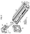
- Fig. 2 represents the process cartridge 200 that houses the developing device and a toner supply unit 300 for supplying toner from the toner tanks T1 to T4.
- the process cartridge 200 provided with the photosensitive drum 125K for which a development process is carried out by the developing device 126K that supplies black toner is shown as an example of the image forming devices.
- the lower right side of Fig. 3 corresponds to the front side of Fig. 1, and the upper left side of Fig. 3 corresponds to the rear side of Fig. 1.
- the developing device 126K is housed in the metal process cartridge 200 and disposed in the inside thereof so as to be adjacent to the photosensitive drum 125K whose part of the peripheral surface is exposed from an opening 200A formed on the process cartridge 200.
- a supplying unit 201 to which toner is supplied from the toner supply unit 300 is provided to a portion of the process cartridge 200 and is composed of the connecting unit 201 (hereinafter, the supplying unit is named as the connecting unit 201) jutting outwardly from the surface of the process cartridge 200.
- the connecting unit 201 is a portion that communicates with a stirring and mixing unit inside the developing device 126K and is inserted with an end of a supply member (pipe) 303 extended from the toner supply unit 300 described later. Furthermore, engagement with the supply member 303 is released by pulling out the process cartridge 200 together with the connecting unit 201 to the lower right side in Fig. 2. Thus, maintenance of the process cartridge 200 can be performed.
- the toner supply unit 300 is a mechanism to which toner is supplied from the toner tank (any member shown by the reference symbols T1 to T4 in Fig. 1) and is provided with a hopper 301 disposed adjacently to the toner tank.
- a stirring member (not shown) is provided inside the hopper 301, and the stirring member is rotatably driven by a driving motor 302 attached to the hopper 301 and transfers (supplies) toner toward the supply member 303.
- a structure for cooling the developing device 126K that is provided with a structure of receiving toner supply from the toner supply unit 300 and that is housed in the process cartridge 200 is provided.
- the structure is explained below.
- a fan 400 as an airflow generating unit is disposed in the longitudinal direction of the process cartridge 200, that is, along the axis direction of a developing sleeve 126K1 in the developing device 126K, on the upstream side in the transfer (supply) direction of toner from the toner supply unit 300, and on the side of the toner supply unit 300.
- the fan 400 is separated from the process cartridge 200 and attached to a supporting unit (not shown) provided in a position communicable to the outside of the image forming apparatus 120.
- the airflow generation direction shown by the reference symbol F in Fig. 3, that is, an airflow direction is set to approximately the same direction as the toner transfer (supply) direction shown by the reference symbol F1 in Fig. 3.
- toner transferred from the supply member 303 which is extended from the toner supply unit 300 and inserted into the connecting unit 201 of the developing device 126K, to the developing device 126K is pushed to the side of the developing device 126K because the airflow direction of the fan 400 is set to approximately the same as the toner transfer (supply) direction. Accordingly, little toner leaks from the connecting unit 201 to the outside to scatter. That is, the connecting unit 201 and the end of the supply member 303 have a dimensional relation in which a fitting width corresponding to an allowance at the time of insertion and withdrawal is created so that the withdrawal and the insertion of the supply member 303 can easily be carried out.
- toner is facilitated to flow toward the inside of the developing device 126K along the direction of airflow generated by the fan 400 without leaking to the outside.
- the process cartridge 200 is disposed and fixed in an inserting and detaching unit 500 provided inside the image forming apparatus 120.
- the fan 400 is supported by a supporting unit 500A included in the inserting and detaching unit 500 on the side of the image forming apparatus 120.
- a partition member 600 is provided adjacently to the space in which the process cartridge 200 is disposed.
- the space partitioned by the partition member 600 is positioned in the airflow direction of the fan 400, in other words, in the direction orthogonal to the airflow moving direction, and the process cartridge 200 and the electrical component 700 are arranged adjacently in the direction orthogonal to the airflow.
- cooling by the fan 400 is carried out for such a positional arrangement of respective devices.
- the airflow from the fan 400 is diverted by the partition member 600 extended in the length that can cover approximately the whole area from the position near the air blowout portion of the fan 400 to the longitudinal direction of the process cartridge 200 and the electrical component 700, and is allowed to flow through each space.
- a heat radiating member made of metal and a heat shielding member such as heat insulating resin are used.
- a heat radiating member When a heat radiating member is used, it functions as a heat sink.
- a heat shielding member When a heat shielding member is used, it functions to shield heat conduction to adjacent devices.
- the air blowout portion of the fan 400 faces both spaces partitioned by the partition member 600.
- the airflow generated by the fan 400 flows along the longitudinal direction of the process cartridge 200 that is the same direction as the transfer (supply) direction of toner and the direction of the loaded electrical component 700 as shown by the reference characters FA and FB in Fig. 4, respectively, and each device is cooled by contact with the airflow.
- the moving direction of airflow by the fan 400 is the same as the transfer (supply) direction of toner from the toner supply unit 300, and therefore, in addition to carrying out cooling, toner scattering can be prevented by pushing toner transferred in the connecting unit 201 on the side of the developing device 126K into the inside of the developing device 126K.
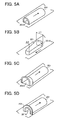
- the structures shown in Figs. 5A to 5D are used as a structure for preventing toner from scattering in the connecting unit 201.
- Figs. 5A to 5D are diagrams of the connecting unit 201. In Figs. 5A to 5D, various different structures are shown.
- the connecting unit 201 is a dome-shaped member in a half-column shape whose one end in the longitudinal direction parallel to the moving direction of airflow shown by an arrow is closed.
- the supply member 303 from the toner supply unit 300 is inserted into and detached from an attachment opening 201A formed at the other end of the connecting unit 201 in the longitudinal direction.
- the attachment opening 201A is in an approximately circle shape large enough to insert the end of the supply member 303, and the end of the supply member 303 is pressed into the attachment opening 201A.
- Fig. 5B is a diagram to represent the connecting unit 201 viewed from the downstream side of the moving direction of airflow shown by an arrow, which is opposite to that shown in Fig. 5A.
- the sectional shape of the connecting unit 201 parallel to the moving direction of airflow generated by the fan 400 is in a taper shape (visible plane dimension L1>L2). Accordingly, toner-flows flown into the inside of the connecting unit 201 is rectified to flows that converge along the sectional shape of the connecting unit 201, and therefore air entering from the gap becomes in conformity with the rectified flows. Thus, turbulent flows disappear, and the problem of external toner scattering caused by the turbulent flows can be solved.
- the structure shown in Fig. 5C is a structure in which for the attachment opening 201A of the connecting unit 201 positioned on the upstream side of the moving direction of airflow, the diameter of the opening end side is enlarged. Even when outside air unexpectedly comes in from the gap depending on the size of the gap, flows that converge near the attachment opening 201A are generated and rectified. Therefore, turbulent flows in the gap are suppressed, and toner scattering caused by turbulent flows can be prevented.
- a scattering prevention member 202 for preventing toner from scattering is attached to the outer peripheral face of the attachment opening 201A of the connecting unit 201. Therefore, toner leaked from the gap between the inner face of the attachment opening 201A and the outer peripheral face of the supply member 303 is prevented from scattering along the airflow direction of the fan 400 (in Fig. 5D, corresponding to the moving direction of airflow shown by an arrow) toward the center side of the process cartridge, that is, the position in which the photosensitive drum 125K shown in Fig. 2 is exposed to the outside. Accordingly, it is possible to prevent toner from leaking from the attachment opening 201A and scattering to the surface of the photosensitive drum or near the periphery thereof.
- a thin plate such as Mylar film is used as the scattering prevention member 202.
- a filter capable of adsorbing toner can be used in place of the thin plate.
- the connecting unit 201 it is possible to rectify the airflow due to the shaping of the structure of the connecting unit 201. Accordingly, it is possible to prevent toner, which is supposed to be pushed into the inside of the developing device 126K by setting direction of airflow using the fan 400, from scattering caused by turbulent flows generated at the connecting unit 201. Therefore, the toner can be prevented from scattering to the development processing units and the inside of the apparatus.
- the time when the process cartridge is exchanged is considered as one of cases in which toner scattering occurs, and therefore toner leaked from the process cartridge at the time of exchange is prevented from scattering inside the image forming apparatus 120.
- a structure for preventing scattering of the toner is explained below.
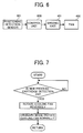
- Fig. 6 is a block diagram of a control unit 800 used for carrying out drive control of the fan 400.
- the control unit 800 uses a microprocessor capable of sequence control for image forming process.
- a positioning detection sensor 801 that determines a position of the process cartridge 200 is connected to an inputting unit in the control unit 800, and a driving unit 401 of the fan 400 is connected to the output side.
- control unit 800 determines that the process cartridge 200 has been removed according to, for example, ON signal from the positioning detection sensor 801 when the process cartridge 200 is removed from the setting position for exchange.
- the control unit 800 determines the state that the positioning detection sensor 801 is changed again to OFF signal, and determines that the process cartridge 200 has been loaded.
- the rotation direction of the fan 400 is reversed from the rotation direction for performing an ordinary image formation, for a predetermined time period from the time when the process cartridge 200 is loaded, which is judged based on a signal from the positioning detection sensor 801.
- Fig. 7 is a flowchart of an operation performed by the control unit 800.
- the rotation of the fan 400 is reversed for a predetermined time.
- the predetermined time in this case is set to approximately from 30 seconds to one minute and corresponds to a time from the time of loading for exchange to a short time elapsed after the load completion.
- the rotation of the fan 400 is switched to rotation (normal rotation) with which the moving direction of airflow in the same direction as the toner transfer (supply) direction can be obtained.
- the fan 400 used as an airflow generating unit is controlled for normal and reverse rotation and there are members in the apparatus that toner scattered in the apparatus sometimes adheres to or comes in contact with at the time of reversing rotation. Therefore, attachment of a filter is possible to adsorb the toner scattered at the time of the reverse rotation.
- a seal member that has flexibility or elasticity such as sponge to the outer peripheral face of the end on the insertion side of the supply member 303.
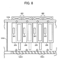
- Fig. 8 represents a structure in which the fans 400 as airflow generating units in the image forming apparatus 120 capable of forming a full-color image are provided so that the fans 400 correspond to the process cartridges 200 that are equipped with the developing devices for each color.
- the reference symbol 120B represents a partition board that thermally shields the integrated setting portion of the process cartridges from, for example, the setting portion for the electrical component board.
- the fans 400 are attached to one side of a main body case 120A in the image forming apparatus 120 corresponding to the setting positions of the process cartridges 200 and outlets 120A1 are provided on the other side of the main body case 120A. Accordingly, airflows from the fans 400 flow along the longitudinal direction of the process cartridges 200 as shown by the arrows and discharged from the outlets 12CA1 to the outside.
- cooling can be carried out for each of the process cartridges 200 individually and the fan 400 can be made small, which is different from a case where an airflow driving source for cooling the entire apparatus is provided.
- the fan 400 is drive-controlled to be suitable for the condition of temperature rising in each process cartridge, that is, selectively driven, it is possible to prevent an increase in power consumption caused by driving the fan 400 for a process cartridge that is not needed to be cooled. Therefore, it is possible to save energy.
- cooling is necessary for temperature management of the entire area of the image forming apparatus 120, it is, of course, possible even for the fan for a process cartridge not in working to be driven.
- the present invention it is possible to prevent toner solidification by cooing the developing device.
- the direction of airflow at the time of cooling is approximately the same as the toner supply direction toward the developing device, toner supplied is pushed into the inside of the developing device, and toner scattering can be prevented.
- the attaching unit for the toner supply path is in a taper shape such that the size thereof becomes gradually smaller from the upstream side to the downstream side of the moving direction of airflow, it is facilitated for the airflow not only to enter the inside of the attaching unit but also to be rectified. Therefore, it is possible to facilitate toner to be pushed into the inside of the developing device and to be prevented from scattering.
- toner scattering prevention member is provided in the attaching unit, toner can be securely prevented from unexpected scattering.
- an air blowing unit capable of generating a forced airflow is used as the airflow generating unit, it is possible to push toner for supply toward the developing device and prevent toner from scattering.
- the developing device is formed of a metal casing, the efficiency of cooling using airflow can be enhanced.
Landscapes
- Physics & Mathematics (AREA)
- General Physics & Mathematics (AREA)
- Life Sciences & Earth Sciences (AREA)
- Engineering & Computer Science (AREA)
- Atmospheric Sciences (AREA)
- Biodiversity & Conservation Biology (AREA)
- Ecology (AREA)
- Environmental & Geological Engineering (AREA)
- Environmental Sciences (AREA)
- Control Or Security For Electrophotography (AREA)
- Dry Development In Electrophotography (AREA)
- Electrophotography Configuration And Component (AREA)
Abstract
Description
- The present document incorporates by reference the entire contents of
Japanese priority document, 2006-042590 filed in Japan on February 20, 2006 - The present invention relates to a technology for cooling inside of an image forming apparatus.
- In an image forming apparatus such as a copying machine, a printer, a facsimile machine, or a printing press, an electrostatic latent image formed on a latent image carrier is processed into a visible image in a development process, the visible image is electrostatically transferred on a sheet such as a recording paper that is one of recording media, and the transferred visible image is heated and fixed on the recording paper to create a copied material or a recorded material.
- On the other hand, in the image forming apparatus, a process cartridge structure (hereinafter, "process cartridge") is often employed. In the process cartridge, devices that carry out image forming process for each latent image carrier are integrated and arranged in the same case as that of the latent image carrier and the case is provided detachably in the main body of the image forming apparatus.
- A technology for the process cartridge is disclosed in, for example,
Japanese Patent Application Laid-Open No. 2004-271703 - In the image forming apparatus, several devices that are used as heat generating sources are installed. Devices that are used as the heat generating sources include the fixing device, electromagnetic devices such as a motor and a crutch, and a microchip used for control. Heat from the heat generating sources causes a rise in atmospheric temperature in the image forming apparatus, which sometimes causes thermal adverse effects on the devices loaded therein.
- For example, toner is used for a developer in the developing device and the toner is sometimes solidified owing to a temperature rise inside the developing device. Accordingly, desired control of supplying the developer cannot sometimes be carried out. Particularly, in recent years, since it is required to downsize the image forming apparatus and speed-up an image processing, a temperature in the device or the process cartridge rises caused by an increased packing density of devices inside the image forming apparatus and an increased stirring speed of the developer inside the developing device.
- Due to a temperature rise in the process cartridge, which accommodates the developing device, abnormal images such as development defect and white lines caused by repeated fusion and solidification of toner as described above are often generated.
- Thus, conventionally, a technology in which heat is exhausted from a target developing device or process cartridge by sending air to the inside of the casing used for the process cartridge and the developing device is disclosed in
Japanese Patent Application Laid-Open No. 2005-173226 Japanese Patent Applications Laid-Open Nos. 2004-109868 2002-278268 H10-91228 - Moreover,
Japanese Patent Application Laid-Open No. 2004-139031 - In the technologies disclosed above, a fan is used as a forced-airflow generating unit, and a space is necessary inside the drum and the process cartridge, through which airflows generated by the fan pass. Moreover, when the developing device is targeted and when toner is scattered by the generated cooling airflow, the inside of the device is sometimes stained. Therefore, an airtight structure for preventing toner from scattering have to be provided, and the apparatus structure needs to be large accordingly.
- Image forming apparatuses are targeted to form not only a monochrome image but also a multicolored image such as a full-color image. Accordingly, the number of developing devices increases corresponding to the number of colors of an image to be formed, more space for setting developing devices in the image forming apparatus is required, and therefore downsizing of the image forming apparatus is difficult.
- It is an object of the present invention to at least partially solve the problems in the conventional technology.
- According to one aspect of the present invention, a cooling structure for cooling a developing structure, the developing structure including a developing unit that develops an image by using toner and a toner supply unit that supplies toner to the developing unit, includes a cooling unit that cools the developing unit by generating an airflow in a direction that is approximately same as a direction of supply of toner from the toner supply unit to the developing unit.
- According to another aspect of the present invention, an image forming apparatus includes a developing structure that includes a developing unit that develops an image by using toner; and a toner supply unit that supplies toner to the developing unit; and a cooling unit that cools the developing unit by generating an airflow in a direction that is approximately same as a direction of supply of toner from the toner supply unit to the developing unit.
- The above and other objects, features, advantages and technical and industrial significance of this invention will be better understood by reading the following detailed description of presently preferred embodiments of the invention, when considered in connection with the accompanying drawings.
-
- Fig. 1 is a side view of an image forming apparatus with a cooling structure according to an embodiment of the present invention;
- Fig. 2 is a perspective view of an arrangement of a process cartridge, a toner supply unit, and a fan used for the cooling structure;
- Fig. 3 is a side view of the arrangement shown in Fig. 2;
- Fig. 4 is a side view of the process cartridge and the fan accommodated in the image forming apparatus;
- Figs. 5A to 5D are diagrams of an attaching unit of a supply path in the process cartridge and the toner supply unit shown in Fig. 2;
- Fig. 6 is a block diagram of a control unit used for the cooling structure;
- Fig. 7 is a flowchart of an operation performed by the control unit; and
- Fig. 8 is a plan view of another example of the cooling structure.
- Exemplary embodiments of the present invention are described in detail below with reference to the accompanying drawings.
- Fig. 1 is a side view of an
image forming apparatus 120 with a sheet delivery device according to an embodiment of the present invention. Theimage forming apparatus 120 is a tandem type color printer and is capable of forming monochrome or full-color images. Theimage forming apparatus 120 can be a copying machine, a facsimile machine, a printing press, or the like. - The
image forming apparatus 120 includesimage forming devices transfer device 122, amanual feed tray 123, a feeding-outroller 123A, apaper feed cassette 124A, apaper feeder 124,resist rollers 133, and afixing device 110. Each of theimage forming devices transfer device 122 is disposed opposite to each of theimage forming devices manual feed tray 123 and the feeding-outroller 123A serve as a sheet feeding unit that feeds a recording sheet to a transfer area between theimage forming devices transfer device 122 that are arranged opposite to each other. Thepaper feed cassette 124A is provided in thepaper feeder 124. Theresist rollers 133 feed the recording sheet delivered from themanual feed tray 123 or thepaper feed cassette 124A in accordance with timing of image formation by theimage forming devices fixing device 110 carries out fixation of an image on the recording sheet that is a sheet medium after the sheet medium is transferred to the transfer area. - The
fixing device 110 uses a heat-roller fixing method in which a toner image on the recording sheet is fixed through a melting-softening processing and a permeation processing. By the fixing process, the toner image is fixed on the recording sheet by the action of heat and pressure using aheat roller 110A and apressure roller 110B that sandwich a delivery path for the recording sheet and are able to come in contact with each other. - In the
transfer device 122, a belt (hereinafter, "transfer belt") 122A that is wound around a plurality of rollers is used as a transfer body,transfer bias units image forming devices image forming devices - In the
transfer device 122, a secondary transfer-bias unit 122F is arranged in the delivery path of a recording sheet. The secondary transfer-bias unit 122F transfers the toner images sequentially superimposed and transferred on thetransfer belt 122A, on a recording sheet all at once. - For the
image forming apparatus 120, any ordinary paper commonly used for copying and the like, over head projector (OHP) sheets, 90K paper such as a card and a postcard, a cardboard whose basis weight is equal to or heavier than ca. 100 g/m2, and so-called special sheets with thermal capacity larger than a paper such as an envelop can be used as the recording sheet. - The
image forming devices image forming devices image forming device 121K is explained on behalf of theimage forming devices - The
image forming device 121K includes aphotosensitive drum 125K as an electrostatic-latent image carrier, acharging device 127K, a developingdevice 126K, and acleaning device 128K that are sequentially disposed along the rotation direction of thephotosensitive drum 125K. Furthermore, theimage forming device 121K is configured so that an electrostatic latent image based on image information corresponding to a color obtained through a color-separation by a writing light 129K from awriting device 129 is formed between the chargingdevice 127K and the developingdevice 126K. The electrostatic-latent image carrier can be in a belt shape other than in a drum shape. These devices arranged in the periphery of the photosensitive drum for image formation, in other words, devices for image formation are accommodated in aprocess cartridge 200 that is constructed in a unit structure provided with a case shown in Fig. 2. - In the
image forming apparatus 120, thetransfer device 122 is arranged obliquely, and therefore space occupied by thetransfer device 122 in the horizontal direction can be made small. - Next, image formation is explained focusing on the
image forming device 121K that forms an image using black toner. Note that the otherimage forming devices photosensitive drums 125M, 125C, and 125Y and developingdevices - At the time of image formation, the
photosensitive drum 125K is rotatably driven by a main motor (not shown) and discharged by alternating current (AC) bias (direct current (DC) component is zero) applied to thecharging device 127K, and the surface potential thereof is set to a standard potential of approximately -50 volts. - The
photosensitive drum 125K is charged uniformly to a potential approximately equal to DC component by being applied with DC bias superimposed with AC bias by the chargingdevice 127K, and the surface potential thereof is charged to between ca. -500 volts and -700 volts (target charge potential is determined by a process control unit). - When the
photosensitive drum 125K is uniformly charged, a writing step is carried out. An image subjected to writing is written to form an electrostatic latent image using thewriting device 129 based on digital image information from a controller unit (not shown). In other words, in thewriting device 129, laser light emitted from a laser light source based on emission signals for laser diode that has been converted into binary for every color corresponding to the digital image information is irradiated on the respective photosensitive drums, in this case on thephotosensitive drum 125K, via a cylinder lens (not shown), apolygon motor 129A, anfθ lens 129B, first to third mirrors, and a wide toroidal lens (WTL). Thereafter, the surface potential of the irradiated portion of the surface of the photosensitive drum becomes ca. -50 volts, and an electrostatic latent image corresponding to the image information is formed. - The electrostatic latent image formed on the
photosensitive drum 125K is processed into a visible image by the developingdevice 126K using color toner that has a complementary color relation to a color that has been obtained through color-separation. At a developing step, toner (Q/M: -20 µC/g to -30 µC/g) is developed exclusively on the image portion whose potential is decreased by the irradiation of writing light by applying DC of between -300 volts and -500 volts superimposed with AC bias to a developing sleeve, and a toner image corresponding to the image information is formed. - The toner image of each color processed into a visible image at the developing step is transferred on a recording sheet fed out by the resist
rollers 133 with a resist timing set. The recording sheet is applied with attachment bias by a sheet-attachment bias unit composed of rollers, before the recording sheet reaches thetransfer belt 122A and is electrostatically attached to thetransfer belt 122A. - The
transfer belt 122A is electrostatically transferred with the toner images from the photosensitive drums by applying bias whose polarity is opposite to that of the toner by thetransfer bias units transfer device 122 in the positions opposite to the photosensitive drums in the image forming devices, and the toner images superimposed and transferred are collectively transferred onto the recording sheet by the secondarytransfer bias unit 122F. - The recording sheet passed through the transfer step for each color is allowed to self-strip from the
transfer belt 122A at a roller on the driving side of a transfer belt unit (shown by the reference symbol 122A1 in Fig. 1) and delivered toward the fixingdevice 110. The recording sheet then passes through a fixing nip formed by the fixing belt and the pressure roller to make the toner image be fixed on the recording sheet and is delivered to apaper delivery tray 132. - In the
image forming apparatus 120 shown in Fig. 1, image formation not only on one side of the recording sheet to be delivered after fixation but also on two sides thereof can be carried out. At the time of two-side image formation, the recording sheet is delivered to a reverse circulation path RP after the image is fixed on one side and fed out toward the resistrollers 133 by feeding-out rollers RP1 that are positioned at an end of the reverse circulation path RP and that serves for feeding out the recording sheet from themanual feed tray 123. Switching of delivery paths for a recording sheet at the time of image formation from one side to two sides is carried out by a delivery-path switching claw RP2 arranged in the rear of the fixingdevice 110. - The delivery-path switching claw RP2 is provided in a delivering unit used as a sheet delivering device described later and switches the delivery paths according to sheet delivery modes.
- Each physical property such as the charge potential is not limited to the values described above, and it is a matter of course that these values can be changed according to colors, darkness, and the like. Furthermore, in Fig. 1, the reference symbols T1 to T4 represent supply tanks of toner used for the developing devices. The supply tank is in a bottle shape that extends from the front side to the rear side in the figure and has a structure in which toner is supplied from the rear side in the figure to the developing device.
- In the
image forming apparatus 120, thetransfer belt 122A used for thetransfer device 122 is also obliquely stretched to make the length in the height direction small as described above. - The
image forming devices image forming apparatus 120 are housed in respective metal process cartridges that is detachable by sliding the developing devices used for a processing of making an electrostatic latent image into a visible image, from the rear side to the front side in Fig. 1 with respect to the inside of the main body of theimage forming apparatus 120. Furthermore, theimage forming devices - Fig. 2 represents the
process cartridge 200 that houses the developing device and atoner supply unit 300 for supplying toner from the toner tanks T1 to T4. In Fig. 2, theprocess cartridge 200 provided with thephotosensitive drum 125K for which a development process is carried out by the developingdevice 126K that supplies black toner, is shown as an example of the image forming devices. The lower right side of Fig. 3 corresponds to the front side of Fig. 1, and the upper left side of Fig. 3 corresponds to the rear side of Fig. 1. - As shown in Fig. 2, the developing
device 126K is housed in themetal process cartridge 200 and disposed in the inside thereof so as to be adjacent to thephotosensitive drum 125K whose part of the peripheral surface is exposed from anopening 200A formed on theprocess cartridge 200. - A supplying
unit 201 to which toner is supplied from thetoner supply unit 300 is provided to a portion of theprocess cartridge 200 and is composed of the connecting unit 201 (hereinafter, the supplying unit is named as the connecting unit 201) jutting outwardly from the surface of theprocess cartridge 200. The connectingunit 201 is a portion that communicates with a stirring and mixing unit inside the developingdevice 126K and is inserted with an end of a supply member (pipe) 303 extended from thetoner supply unit 300 described later. Furthermore, engagement with thesupply member 303 is released by pulling out theprocess cartridge 200 together with the connectingunit 201 to the lower right side in Fig. 2. Thus, maintenance of theprocess cartridge 200 can be performed. - The
toner supply unit 300 is a mechanism to which toner is supplied from the toner tank (any member shown by the reference symbols T1 to T4 in Fig. 1) and is provided with ahopper 301 disposed adjacently to the toner tank. A stirring member (not shown) is provided inside thehopper 301, and the stirring member is rotatably driven by a drivingmotor 302 attached to thehopper 301 and transfers (supplies) toner toward thesupply member 303. - In the embodiment, a structure for cooling the developing
device 126K that is provided with a structure of receiving toner supply from thetoner supply unit 300 and that is housed in theprocess cartridge 200 is provided. The structure is explained below. - Near the
process cartridge 200, afan 400 as an airflow generating unit is disposed in the longitudinal direction of theprocess cartridge 200, that is, along the axis direction of a developing sleeve 126K1 in the developingdevice 126K, on the upstream side in the transfer (supply) direction of toner from thetoner supply unit 300, and on the side of thetoner supply unit 300. - The
fan 400 is separated from theprocess cartridge 200 and attached to a supporting unit (not shown) provided in a position communicable to the outside of theimage forming apparatus 120. The airflow generation direction shown by the reference symbol F in Fig. 3, that is, an airflow direction is set to approximately the same direction as the toner transfer (supply) direction shown by the reference symbol F1 in Fig. 3. - It is facilitated that toner transferred from the
supply member 303, which is extended from thetoner supply unit 300 and inserted into the connectingunit 201 of the developingdevice 126K, to the developingdevice 126K is pushed to the side of the developingdevice 126K because the airflow direction of thefan 400 is set to approximately the same as the toner transfer (supply) direction. Accordingly, little toner leaks from the connectingunit 201 to the outside to scatter. That is, the connectingunit 201 and the end of thesupply member 303 have a dimensional relation in which a fitting width corresponding to an allowance at the time of insertion and withdrawal is created so that the withdrawal and the insertion of thesupply member 303 can easily be carried out. In this case, a slight gap is sometimes produced, and toner sometimes leaks from the gap to the outside to scatter. However, in the structure of the embodiment, toner is facilitated to flow toward the inside of the developingdevice 126K along the direction of airflow generated by thefan 400 without leaking to the outside. - On the other hand, as shown in Fig. 4, the
process cartridge 200 is disposed and fixed in an inserting and detachingunit 500 provided inside theimage forming apparatus 120. In the inserting and detachingunit 500 provided on the side of theimage forming apparatus 120, thefan 400 is supported by a supportingunit 500A included in the inserting and detachingunit 500 on the side of theimage forming apparatus 120. - In the inserting and detaching
unit 500, apartition member 600 is provided adjacently to the space in which theprocess cartridge 200 is disposed. An electrical component (board) 700 attached with a power device that is one of the electrical components to be heat generating sources, and a driving circuit driven by the power device(shown by thereference symbol 700A in Fig. 4) is disposed in the space partitioned by thepartition member 600. - The space partitioned by the
partition member 600 is positioned in the airflow direction of thefan 400, in other words, in the direction orthogonal to the airflow moving direction, and theprocess cartridge 200 and theelectrical component 700 are arranged adjacently in the direction orthogonal to the airflow. - In the embodiment, cooling by the
fan 400 is carried out for such a positional arrangement of respective devices. As shown in Fig. 4, the airflow from thefan 400 is diverted by thepartition member 600 extended in the length that can cover approximately the whole area from the position near the air blowout portion of thefan 400 to the longitudinal direction of theprocess cartridge 200 and theelectrical component 700, and is allowed to flow through each space. - For the
partition member 600 described above, a heat radiating member made of metal and a heat shielding member such as heat insulating resin are used. When a heat radiating member is used, it functions as a heat sink. When a heat shielding member is used, it functions to shield heat conduction to adjacent devices. - The air blowout portion of the
fan 400 faces both spaces partitioned by thepartition member 600. The airflow generated by thefan 400 flows along the longitudinal direction of theprocess cartridge 200 that is the same direction as the transfer (supply) direction of toner and the direction of the loadedelectrical component 700 as shown by the reference characters FA and FB in Fig. 4, respectively, and each device is cooled by contact with the airflow. - In the structure, the moving direction of airflow by the
fan 400 is the same as the transfer (supply) direction of toner from thetoner supply unit 300, and therefore, in addition to carrying out cooling, toner scattering can be prevented by pushing toner transferred in the connectingunit 201 on the side of the developingdevice 126K into the inside of the developingdevice 126K. - In the embodiment, the structures shown in Figs. 5A to 5D are used as a structure for preventing toner from scattering in the connecting
unit 201. - Figs. 5A to 5D are diagrams of the connecting
unit 201. In Figs. 5A to 5D, various different structures are shown. - In Figs. 5A to 5D, the connecting
unit 201 is a dome-shaped member in a half-column shape whose one end in the longitudinal direction parallel to the moving direction of airflow shown by an arrow is closed. Thesupply member 303 from thetoner supply unit 300 is inserted into and detached from anattachment opening 201A formed at the other end of the connectingunit 201 in the longitudinal direction. - In the structure shown in Fig. 5A, the
attachment opening 201A is in an approximately circle shape large enough to insert the end of thesupply member 303, and the end of thesupply member 303 is pressed into theattachment opening 201A. - When the end is inserted into the
attachment opening 201A, a slight gap is formed between the attachment opening 201A and the outer peripheral face of the end of thesupply member 303 to enhance the workability at the time of withdrawal and insertion. However, if the gap is small and when airflow by thefan 400 enters, the airflow flowing through the gap portion becomes turbulent and toner supposed to be pushed into the inside of the developingdevice 126K sometimes scatters outside. Thus, in the embodiment, a structure in which scattering caused by toner leakage from theattachment opening 201A does not occur is adopted. - Fig. 5B is a diagram to represent the connecting
unit 201 viewed from the downstream side of the moving direction of airflow shown by an arrow, which is opposite to that shown in Fig. 5A. - In Fig. 5B, the sectional shape of the connecting
unit 201 parallel to the moving direction of airflow generated by thefan 400 is in a taper shape (visible plane dimension L1>L2). Accordingly, toner-flows flown into the inside of the connectingunit 201 is rectified to flows that converge along the sectional shape of the connectingunit 201, and therefore air entering from the gap becomes in conformity with the rectified flows. Thus, turbulent flows disappear, and the problem of external toner scattering caused by the turbulent flows can be solved. - The structure shown in Fig. 5C is a structure in which for the attachment opening 201A of the connecting
unit 201 positioned on the upstream side of the moving direction of airflow, the diameter of the opening end side is enlarged. Even when outside air unexpectedly comes in from the gap depending on the size of the gap, flows that converge near theattachment opening 201A are generated and rectified. Therefore, turbulent flows in the gap are suppressed, and toner scattering caused by turbulent flows can be prevented. - In the structure shown in Fig. 5D, a
scattering prevention member 202 for preventing toner from scattering is attached to the outer peripheral face of the attachment opening 201A of the connectingunit 201. Therefore, toner leaked from the gap between the inner face of the attachment opening 201A and the outer peripheral face of thesupply member 303 is prevented from scattering along the airflow direction of the fan 400 (in Fig. 5D, corresponding to the moving direction of airflow shown by an arrow) toward the center side of the process cartridge, that is, the position in which thephotosensitive drum 125K shown in Fig. 2 is exposed to the outside. Accordingly, it is possible to prevent toner from leaking from the attachment opening 201A and scattering to the surface of the photosensitive drum or near the periphery thereof. - In the embodiment, a thin plate such as Mylar film is used as the
scattering prevention member 202. However, a filter capable of adsorbing toner can be used in place of the thin plate. - In the embodiment, it is possible to rectify the airflow due to the shaping of the structure of the connecting
unit 201. Accordingly, it is possible to prevent toner, which is supposed to be pushed into the inside of the developingdevice 126K by setting direction of airflow using thefan 400, from scattering caused by turbulent flows generated at the connectingunit 201. Therefore, the toner can be prevented from scattering to the development processing units and the inside of the apparatus. - The time when the process cartridge is exchanged is considered as one of cases in which toner scattering occurs, and therefore toner leaked from the process cartridge at the time of exchange is prevented from scattering inside the
image forming apparatus 120. A structure for preventing scattering of the toner is explained below. - Fig. 6 is a block diagram of a
control unit 800 used for carrying out drive control of thefan 400. Thecontrol unit 800 uses a microprocessor capable of sequence control for image forming process. - As members related to the embodiment, a
positioning detection sensor 801 that determines a position of theprocess cartridge 200 is connected to an inputting unit in thecontrol unit 800, and adriving unit 401 of thefan 400 is connected to the output side. - After the
control unit 800 determines that theprocess cartridge 200 has been removed according to, for example, ON signal from thepositioning detection sensor 801 when theprocess cartridge 200 is removed from the setting position for exchange, thecontrol unit 800 determines the state that thepositioning detection sensor 801 is changed again to OFF signal, and determines that theprocess cartridge 200 has been loaded. The rotation direction of thefan 400 is reversed from the rotation direction for performing an ordinary image formation, for a predetermined time period from the time when theprocess cartridge 200 is loaded, which is judged based on a signal from thepositioning detection sensor 801. - Fig. 7 is a flowchart of an operation performed by the
control unit 800. In Fig. 7, if it is determined that theprocess cartridge 200 has been exchanged with a new process cartridge by judging an input state of OFF signal of thepositioning detection sensor 801, the rotation of thefan 400 is reversed for a predetermined time. The predetermined time in this case is set to approximately from 30 seconds to one minute and corresponds to a time from the time of loading for exchange to a short time elapsed after the load completion. - Accordingly, even if part of toner leaks and scatters from the
process cartridge 200 at the time of loading for exchange, an airflow is generated in the direction opposite to the transfer (supply) direction of toner, and therefore, scattering of the toner to the exposed position of the developing sleeve 126K1 on the side of theprocess cartridge 200 or to the inside of the image forming apparatus can be prevented. - After reversing the airflow for the predetermined time, the rotation of the
fan 400 is switched to rotation (normal rotation) with which the moving direction of airflow in the same direction as the toner transfer (supply) direction can be obtained. - In the embodiment, the
fan 400 used as an airflow generating unit is controlled for normal and reverse rotation and there are members in the apparatus that toner scattered in the apparatus sometimes adheres to or comes in contact with at the time of reversing rotation. Therefore, attachment of a filter is possible to adsorb the toner scattered at the time of the reverse rotation. For a structure to prevent toner leakage from the attachment opening 201A of the connectingunit 201, it is possible to attach a seal member that has flexibility or elasticity such as sponge to the outer peripheral face of the end on the insertion side of thesupply member 303. - Fig. 8 represents a structure in which the
fans 400 as airflow generating units in theimage forming apparatus 120 capable of forming a full-color image are provided so that thefans 400 correspond to theprocess cartridges 200 that are equipped with the developing devices for each color. Note that thereference symbol 120B represents a partition board that thermally shields the integrated setting portion of the process cartridges from, for example, the setting portion for the electrical component board. - In this case, the
fans 400 are attached to one side of amain body case 120A in theimage forming apparatus 120 corresponding to the setting positions of theprocess cartridges 200 and outlets 120A1 are provided on the other side of themain body case 120A. Accordingly, airflows from thefans 400 flow along the longitudinal direction of theprocess cartridges 200 as shown by the arrows and discharged from the outlets 12CA1 to the outside. - In this structure, cooling can be carried out for each of the
process cartridges 200 individually and thefan 400 can be made small, which is different from a case where an airflow driving source for cooling the entire apparatus is provided. Moreover, when thefan 400 is drive-controlled to be suitable for the condition of temperature rising in each process cartridge, that is, selectively driven, it is possible to prevent an increase in power consumption caused by driving thefan 400 for a process cartridge that is not needed to be cooled. Therefore, it is possible to save energy. When cooling is necessary for temperature management of the entire area of theimage forming apparatus 120, it is, of course, possible even for the fan for a process cartridge not in working to be driven. - According to an aspect of the present invention, it is possible to prevent toner solidification by cooing the developing device. In addition, since the direction of airflow at the time of cooling is approximately the same as the toner supply direction toward the developing device, toner supplied is pushed into the inside of the developing device, and toner scattering can be prevented.
- According to another aspect of the present invention, it is possible to cool other devices collectively with cooling airflow for the developing device by disposing the electrical component adjacently to the developing device. Therefore, the heat generating sources affecting toner solidification can be cooled collectively.
- According to still another aspect of the present invention, it is possible to block the influence of heat on the developing device by providing the partition member between the developing device and the adjacent electrical component.
- According to still another aspect of the present invention, since the attaching unit for the toner supply path is in a taper shape such that the size thereof becomes gradually smaller from the upstream side to the downstream side of the moving direction of airflow, it is facilitated for the airflow not only to enter the inside of the attaching unit but also to be rectified. Therefore, it is possible to facilitate toner to be pushed into the inside of the developing device and to be prevented from scattering.
- According to still another aspect of the present invention, since a toner scattering prevention member is provided in the attaching unit, toner can be securely prevented from unexpected scattering.
- According to still another aspect of the present invention, since an air blowing unit capable of generating a forced airflow is used as the airflow generating unit, it is possible to push toner for supply toward the developing device and prevent toner from scattering.
- According to still another aspect of the present invention, since a filter is provided in the air blowing unit, it is possible to recover toner scattered in the device at the time of air circulation generated when air is blown.
- According to still another aspect of the present invention, since the developing device is formed of a metal casing, the efficiency of cooling using airflow can be enhanced.
- According to still another aspect of the present invention, it is possible to effectively prevent toner solidification by suppressing heat generation in the device as well as securely prevent toner scattering caused by airflow used at the time of cooling.
- According to still another aspect of the present invention, since recovery of toner scattered at the time of exchanging the developing device is possible by reversing the rotation of the air blowing unit, and therefore, toner scattering at the time of exchange of the developing device can be effectively suppressed.
- Although the invention has been described with respect to a specific embodiment for a complete and clear disclosure, the appended claims are not to be thus limited but are to be construed as embodying all modifications and alternative constructions that may occur to one skilled in the art that fairly fall within the basic teaching herein set forth.
Claims (14)
- A cooling structure for cooling a developing structure, the developing structure including a developing unit (126K, 126C, 126M, and 126Y) that develops an image by using toner and a toner supply unit (300) that supplies toner to the developing unit, the cooling structure comprising:a cooling unit (400) that cools the developing unit (126K, 126C, 126M, and 126Y) by generating an airflow in a direction that is approximately same as a direction of supply of toner from the toner supply unit (300) to the developing unit (126K, 126C, 126M, and 126Y).
- An image forming apparatus (120) comprising:a developing structure that includesa developing unit (126K, 126C, 126M, and 126Y) that develops an image by using toner; anda toner supply unit (300) that supplies toner to the developing unit; anda cooling unit (400) that cools the developing unit (126K, 126C, 126M, and 126Y) by generating an airflow in a direction that is approximately same as a direction of supply of toner from the toner supply unit (300) to the developing unit (126K, 126C, 126M, and 126Y).
- The image forming apparatus (120) according to claim 2, further comprising an electrical component (700) that is arranged near the developing unit (126K, 126C, 126M, and 126Y) in a path of the airflow and that produces heat, wherein the cooling unit (400) cools the electrical component (700) with the airflow.
- The image forming apparatus (120) according to claim 3, wherein the electrical component (700) is arranged in a direction orthogonal to the direction of the airflow.
- The image forming apparatus (120) according to claim 3 or 4, further comprising a partition member (600) arranged between the developing unit (126K, 126C, 126M, and 126Y) and the electrical component (700) for preventing the heat generated in the electrical component (700) from being in contact with the developing unit (126K, 126C, 126M, and 126Y).
- The image forming apparatus (120) according to claim 5, wherein the partition member (600) is made of a heat radiating material.
- The image forming apparatus (120) according to claim 5, wherein the partition member (600) is made of a heat shielding material.
- The image forming apparatus (120) according to any one of claims 2 to 7, whereinthe toner supply unit (300) includes a toner tank (T1 to T4), a toner supply member (303) that supplies toner from the toner tank (T1 to T4) to the developing unit (126K, 126C, 126M, and 126Y), and a connecting unit (201) for connecting the toner supply member (303) to the developing unit (126K, 126C, 126M, and 126Y),the connecting unit (201) is formed in a taper shape such that a diameter of the connecting unit (201) becomes gradually smaller from an upstream side to an downstream side along the direction of the airflow.
- The image forming apparatus (120) according to claim 8, further comprising a scattering prevention member (202) that prevents toner from scattering inside the image forming apparatus (120) and that is arranged on the connecting unit (201).
- The image forming apparatus (120) according to any one of claims 2 to 9, wherein the cooling unit (400) is a fan (400).
- The image forming apparatus (120) according to claim 10, wherein the fan (400) includes a filter for absorbing scattered toner.
- The image forming apparatus (120) according to any one of claims 2 to 11, wherein the developing unit (126K, 126C, 126M, and 126Y) is formed of a metal casing.
- The image forming apparatus (120) according to any one of claims 2 to 12, wherein the developing unit (126K, 126C, 126M, and 126Y) is loaded in a process cartridge (200).
- The image forming apparatus (120) according to any one of claims 2 to 13, wherein the developing unit (126K, 126C, 126M, and 126Y) is detachably provided in the image forming apparatus (120), and the direction of the airflow is reversed from a previous direction for a predetermined time immediately after the developing unit (126K, 126C, 126M, and 126Y) is exchanged to the developing unit (126K, 126C, 126M, and 126Y) in which toner is charged.
Applications Claiming Priority (1)
| Application Number | Priority Date | Filing Date | Title |
|---|---|---|---|
| JP2006042590A JP4913423B2 (en) | 2006-02-20 | 2006-02-20 | Cooling structure and image forming apparatus |
Publications (3)
| Publication Number | Publication Date |
|---|---|
| EP1821159A2 true EP1821159A2 (en) | 2007-08-22 |
| EP1821159A3 EP1821159A3 (en) | 2008-02-27 |
| EP1821159B1 EP1821159B1 (en) | 2016-12-28 |
Family
ID=38066622
Family Applications (1)
| Application Number | Title | Priority Date | Filing Date |
|---|---|---|---|
| EP07102393.1A Not-in-force EP1821159B1 (en) | 2006-02-20 | 2007-02-14 | Cooling structure and image forming apparatus |
Country Status (2)
| Country | Link |
|---|---|
| EP (1) | EP1821159B1 (en) |
| JP (1) | JP4913423B2 (en) |
Families Citing this family (4)
| Publication number | Priority date | Publication date | Assignee | Title |
|---|---|---|---|---|
| JP5322698B2 (en) * | 2009-02-27 | 2013-10-23 | キヤノン株式会社 | Image forming apparatus |
| JP5656061B2 (en) * | 2010-09-24 | 2015-01-21 | 株式会社リコー | Image forming apparatus |
| US9104171B2 (en) | 2013-01-16 | 2015-08-11 | Ricoh Company, Ltd. | Detachable unit and image forming apparatus incorporating same |
| JP2021026036A (en) | 2019-07-31 | 2021-02-22 | 株式会社リコー | Image forming apparatus |
Citations (3)
| Publication number | Priority date | Publication date | Assignee | Title |
|---|---|---|---|---|
| JPS63184774A (en) | 1987-01-28 | 1988-07-30 | Ricoh Co Ltd | Cooling device for developing section |
| JPH0850412A (en) | 1994-05-31 | 1996-02-20 | Ricoh Co Ltd | Image forming device |
| JPH11218987A (en) | 1998-02-02 | 1999-08-10 | Canon Inc | Electrophotographic image forming equipment |
Family Cites Families (10)
| Publication number | Priority date | Publication date | Assignee | Title |
|---|---|---|---|---|
| JPH05133892A (en) * | 1991-11-14 | 1993-05-28 | Ricoh Co Ltd | Toner concentration sensor |
| JP3392256B2 (en) * | 1994-04-22 | 2003-03-31 | 株式会社リコー | Image forming device |
| JPH11296041A (en) * | 1998-04-13 | 1999-10-29 | Minolta Co Ltd | Cleaning device and image forming device using it |
| JP4421702B2 (en) * | 1999-07-23 | 2010-02-24 | 武藤工業株式会社 | Inkjet printer |
| US6549736B2 (en) * | 2000-01-19 | 2003-04-15 | Canon Kabushiki Kaisha | Process cartridge, engaging member therefor and method for mounting developing roller and magnet |
| JP2002182442A (en) * | 2000-12-12 | 2002-06-26 | Konica Corp | Image forming device |
| JP2002258697A (en) * | 2001-02-28 | 2002-09-11 | Toshiba Tec Corp | Image forming device |
| JP2004233986A (en) * | 2003-01-09 | 2004-08-19 | Ricoh Co Ltd | Electrophotographic image forming apparatus, toner transfer device, and toner |
| JP2005227751A (en) * | 2004-01-14 | 2005-08-25 | Ricoh Co Ltd | Auxiliary power supply and image forming apparatus |
| JP3994976B2 (en) * | 2004-03-09 | 2007-10-24 | コニカミノルタビジネステクノロジーズ株式会社 | Toner supply device |
-
2006
- 2006-02-20 JP JP2006042590A patent/JP4913423B2/en not_active Expired - Fee Related
-
2007
- 2007-02-14 EP EP07102393.1A patent/EP1821159B1/en not_active Not-in-force
Patent Citations (3)
| Publication number | Priority date | Publication date | Assignee | Title |
|---|---|---|---|---|
| JPS63184774A (en) | 1987-01-28 | 1988-07-30 | Ricoh Co Ltd | Cooling device for developing section |
| JPH0850412A (en) | 1994-05-31 | 1996-02-20 | Ricoh Co Ltd | Image forming device |
| JPH11218987A (en) | 1998-02-02 | 1999-08-10 | Canon Inc | Electrophotographic image forming equipment |
Also Published As
| Publication number | Publication date |
|---|---|
| JP2007219398A (en) | 2007-08-30 |
| EP1821159A3 (en) | 2008-02-27 |
| EP1821159B1 (en) | 2016-12-28 |
| JP4913423B2 (en) | 2012-04-11 |
Similar Documents
| Publication | Publication Date | Title |
|---|---|---|
| US7941069B2 (en) | Process cartridge having air inlets and outlets for cooling gears disposed in the process cartridge | |
| JP4760602B2 (en) | Image forming apparatus | |
| US7835660B2 (en) | Image forming apparatus and image forming method | |
| EP1657599B1 (en) | Heat extraction unit in an image forming apparatus | |
| CN100517112C (en) | Toner container and toner loading method | |
| JP5252273B2 (en) | Developing device and image forming apparatus | |
| JP4616591B2 (en) | Image forming apparatus | |
| JP5137452B2 (en) | Image forming apparatus | |
| EP1821159B1 (en) | Cooling structure and image forming apparatus | |
| JP4707583B2 (en) | Image forming apparatus | |
| JP2007328194A (en) | Attachable/detachable cartridge and image forming apparatus | |
| JP5640579B2 (en) | Radiation means of image forming apparatus and image forming apparatus | |
| JP5219396B2 (en) | Image forming apparatus | |
| US8886078B2 (en) | Image forming apparatus | |
| JP2012068487A (en) | Image forming device | |
| US20060257161A1 (en) | Heat exhausting structure and image forming apparatus | |
| US10859975B2 (en) | Developing device and image forming apparatus including the same | |
| JP5104087B2 (en) | Image forming apparatus and imaging unit | |
| JP5420048B2 (en) | Image forming apparatus | |
| JP4565942B2 (en) | Image forming apparatus | |
| JP2006139066A (en) | Image forming apparatus | |
| US20250278055A1 (en) | Image forming apparatus | |
| JP3940744B2 (en) | Color image forming apparatus | |
| US20250291313A1 (en) | Image forming apparatus | |
| JP4558426B2 (en) | Image forming apparatus |
Legal Events
| Date | Code | Title | Description |
|---|---|---|---|
| PUAI | Public reference made under article 153(3) epc to a published international application that has entered the european phase |
Free format text: ORIGINAL CODE: 0009012 |
|
| AK | Designated contracting states |
Kind code of ref document: A2 Designated state(s): AT BE BG CH CY CZ DE DK EE ES FI FR GB GR HU IE IS IT LI LT LU LV MC NL PL PT RO SE SI SK TR |
|
| AX | Request for extension of the european patent |
Extension state: AL BA HR MK YU |
|
| PUAL | Search report despatched |
Free format text: ORIGINAL CODE: 0009013 |
|
| AK | Designated contracting states |
Kind code of ref document: A3 Designated state(s): AT BE BG CH CY CZ DE DK EE ES FI FR GB GR HU IE IS IT LI LT LU LV MC NL PL PT RO SE SI SK TR |
|
| AX | Request for extension of the european patent |
Extension state: AL BA HR MK YU |
|
| 17P | Request for examination filed |
Effective date: 20080625 |
|
| AKX | Designation fees paid |
Designated state(s): DE ES FR GB IT NL |
|
| 17Q | First examination report despatched |
Effective date: 20120420 |
|
| GRAP | Despatch of communication of intention to grant a patent |
Free format text: ORIGINAL CODE: EPIDOSNIGR1 |
|
| INTG | Intention to grant announced |
Effective date: 20160803 |
|
| GRAS | Grant fee paid |
Free format text: ORIGINAL CODE: EPIDOSNIGR3 |
|
| GRAA | (expected) grant |
Free format text: ORIGINAL CODE: 0009210 |
|
| AK | Designated contracting states |
Kind code of ref document: B1 Designated state(s): DE ES FR GB IT NL |
|
| REG | Reference to a national code |
Ref country code: GB Ref legal event code: FG4D |
|
| REG | Reference to a national code |
Ref country code: DE Ref legal event code: R096 Ref document number: 602007049293 Country of ref document: DE |
|
| REG | Reference to a national code |
Ref country code: FR Ref legal event code: PLFP Year of fee payment: 11 |
|
| REG | Reference to a national code |
Ref country code: NL Ref legal event code: MP Effective date: 20161228 |
|
| PG25 | Lapsed in a contracting state [announced via postgrant information from national office to epo] |
Ref country code: NL Free format text: LAPSE BECAUSE OF FAILURE TO SUBMIT A TRANSLATION OF THE DESCRIPTION OR TO PAY THE FEE WITHIN THE PRESCRIBED TIME-LIMIT Effective date: 20161228 |
|
| PG25 | Lapsed in a contracting state [announced via postgrant information from national office to epo] |
Ref country code: ES Free format text: LAPSE BECAUSE OF FAILURE TO SUBMIT A TRANSLATION OF THE DESCRIPTION OR TO PAY THE FEE WITHIN THE PRESCRIBED TIME-LIMIT Effective date: 20161228 Ref country code: IT Free format text: LAPSE BECAUSE OF FAILURE TO SUBMIT A TRANSLATION OF THE DESCRIPTION OR TO PAY THE FEE WITHIN THE PRESCRIBED TIME-LIMIT Effective date: 20161228 |
|
| REG | Reference to a national code |
Ref country code: DE Ref legal event code: R097 Ref document number: 602007049293 Country of ref document: DE |
|
| PLBE | No opposition filed within time limit |
Free format text: ORIGINAL CODE: 0009261 |
|
| STAA | Information on the status of an ep patent application or granted ep patent |
Free format text: STATUS: NO OPPOSITION FILED WITHIN TIME LIMIT |
|
| 26N | No opposition filed |
Effective date: 20170929 |
|
| REG | Reference to a national code |
Ref country code: FR Ref legal event code: PLFP Year of fee payment: 12 |
|
| PGFP | Annual fee paid to national office [announced via postgrant information from national office to epo] |
Ref country code: FR Payment date: 20230220 Year of fee payment: 17 |
|
| PGFP | Annual fee paid to national office [announced via postgrant information from national office to epo] |
Ref country code: GB Payment date: 20230220 Year of fee payment: 17 Ref country code: DE Payment date: 20230216 Year of fee payment: 17 |
|
| REG | Reference to a national code |
Ref country code: DE Ref legal event code: R119 Ref document number: 602007049293 Country of ref document: DE |
|
| GBPC | Gb: european patent ceased through non-payment of renewal fee |
Effective date: 20240214 |
|
| PG25 | Lapsed in a contracting state [announced via postgrant information from national office to epo] |
Ref country code: DE Free format text: LAPSE BECAUSE OF NON-PAYMENT OF DUE FEES Effective date: 20240903 |
|
| PG25 | Lapsed in a contracting state [announced via postgrant information from national office to epo] |
Ref country code: GB Free format text: LAPSE BECAUSE OF NON-PAYMENT OF DUE FEES Effective date: 20240214 |
|
| PG25 | Lapsed in a contracting state [announced via postgrant information from national office to epo] |
Ref country code: FR Free format text: LAPSE BECAUSE OF NON-PAYMENT OF DUE FEES Effective date: 20240229 |
|
| PG25 | Lapsed in a contracting state [announced via postgrant information from national office to epo] |
Ref country code: GB Free format text: LAPSE BECAUSE OF NON-PAYMENT OF DUE FEES Effective date: 20240214 Ref country code: FR Free format text: LAPSE BECAUSE OF NON-PAYMENT OF DUE FEES Effective date: 20240229 Ref country code: DE Free format text: LAPSE BECAUSE OF NON-PAYMENT OF DUE FEES Effective date: 20240903 |