EP1821049A1 - Heat exchanger - Google Patents
Heat exchanger Download PDFInfo
- Publication number
- EP1821049A1 EP1821049A1 EP05809549A EP05809549A EP1821049A1 EP 1821049 A1 EP1821049 A1 EP 1821049A1 EP 05809549 A EP05809549 A EP 05809549A EP 05809549 A EP05809549 A EP 05809549A EP 1821049 A1 EP1821049 A1 EP 1821049A1
- Authority
- EP
- European Patent Office
- Prior art keywords
- fins
- heat exchanger
- edges
- burrs
- fin
- Prior art date
- Legal status (The legal status is an assumption and is not a legal conclusion. Google has not performed a legal analysis and makes no representation as to the accuracy of the status listed.)
- Withdrawn
Links
Images
Classifications
-
- F—MECHANICAL ENGINEERING; LIGHTING; HEATING; WEAPONS; BLASTING
- F28—HEAT EXCHANGE IN GENERAL
- F28F—DETAILS OF HEAT-EXCHANGE AND HEAT-TRANSFER APPARATUS, OF GENERAL APPLICATION
- F28F17/00—Removing ice or water from heat-exchange apparatus
- F28F17/005—Means for draining condensates from heat exchangers, e.g. from evaporators
-
- F—MECHANICAL ENGINEERING; LIGHTING; HEATING; WEAPONS; BLASTING
- F24—HEATING; RANGES; VENTILATING
- F24F—AIR-CONDITIONING; AIR-HUMIDIFICATION; VENTILATION; USE OF AIR CURRENTS FOR SCREENING
- F24F1/00—Room units for air-conditioning, e.g. separate or self-contained units or units receiving primary air from a central station
- F24F1/0007—Indoor units, e.g. fan coil units
- F24F1/0059—Indoor units, e.g. fan coil units characterised by heat exchangers
- F24F1/0067—Indoor units, e.g. fan coil units characterised by heat exchangers by the shape of the heat exchangers or of parts thereof, e.g. of their fins
-
- F—MECHANICAL ENGINEERING; LIGHTING; HEATING; WEAPONS; BLASTING
- F28—HEAT EXCHANGE IN GENERAL
- F28F—DETAILS OF HEAT-EXCHANGE AND HEAT-TRANSFER APPARATUS, OF GENERAL APPLICATION
- F28F1/00—Tubular elements; Assemblies of tubular elements
- F28F1/10—Tubular elements and assemblies thereof with means for increasing heat-transfer area, e.g. with fins, with projections, with recesses
- F28F1/12—Tubular elements and assemblies thereof with means for increasing heat-transfer area, e.g. with fins, with projections, with recesses the means being only outside the tubular element
- F28F1/24—Tubular elements and assemblies thereof with means for increasing heat-transfer area, e.g. with fins, with projections, with recesses the means being only outside the tubular element and extending transversely
- F28F1/32—Tubular elements and assemblies thereof with means for increasing heat-transfer area, e.g. with fins, with projections, with recesses the means being only outside the tubular element and extending transversely the means having portions engaging further tubular elements
Definitions
- the present invention relates to a heat exchanger. More particularly, the invention relates to a heat exchanger suitable for use in air conditioners, refrigerators, ice makers and the like.
- this heat exchanger is formed by inserting heat transfer tubes into insertion holes of a perforated fin and then separating the fin at the perforations so that two heat exchangers are formed.
- the conventional heat exchanger shown above in which the fins can be separated at the places of the perforations, is easy to manufacture, having an advantage that heat exchangers of different dimensions can be easily manufactured by separating the fins at the perforations or not separating the fins at the perforations but leaving the perforations as they are.
- the above conventional heat exchanger while having an advantage of easiness in changing dimensional settings of the fins, has a problem that because, in division of the fins, burrs are formed on an outer edge of the heat exchanger formed by dividing the perforated fins at the perforations and corresponding to places of the fins where the perforations have been separated, condensed water (dew drop water) generated on the fins during the use of the heat exchanger may scatter from the fins along the burrs.
- the conventional heat exchanger is used as a heat exchanger on the indoor side of an air conditioner, the condensed water may be scattered indoors by air blows, giving rise to a serious problem.
- an object of the present invention is to provide a heat exchanger which is easy to change in dimensional settings of its fins and which is less liable to scattering of condensed water from the fins and moreover which is kept from impairment of its appearance.
- the present invention provides a heat exchanger comprising:
- edges with burrs present thereon in the first fins or the second fins are so positioned as to be in contact with or opposition to the other edges of the first fins or the second fins, and the edges with the burrs present thereon are positioned inside. Therefore, burrs are present only on the edges that are in contact with or opposition to the second fins, and not on the other edges, among all the edges of the first fins, and moreover burrs are present only on the edges that are in contact with or opposition to the first fins, and not on the other edges, among all the edges of the second fins.
- the heat exchanger of the invention even when used as a heat exchanger on the indoor side of an air conditioner, can be kept from indoor scattering of the condensed water mixed in winds.
- edges with burrs present thereon in the first fins or the second fins are so positioned as to be in contact with or opposition to the other edges of the first fins or the second fins, and the edges with the burrs present thereon are positioned inside. Therefore, burrs are present only on the edges that are in contact with or opposition to the second fins, and not on the other edges, among all the edges of the first fins, and moreover burrs are present only on the edges that are in contact with or opposition to the first fins, and not on the other edges, among all the edges of the second fins. Since the edges having the burrs thereon are never positioned on the outer side of the heat exchanger, the heat exchanger can be kept from impairment of its appearance.
- edges with burrs present thereon in the first fins or the second fins are so positioned as to be in contact with or opposition to the other edges of the first fins or the second fins, and the edges with the burrs present thereon are positioned inside. Therefore, even if condensed water has scattered from the edges having the burrs thereon, the scattered condensed water can be received by the edges that are in contact with or opposition to the edges having the burrs thereon.
- the heat exchanger of the invention even when used as a heat exchanger on the indoor side of an air conditioner, can be kept from indoor scattering of the condensed water mixed in winds.
- the heat exchanger of this invention since the edges having the burrs thereon are never positioned on the outer side of the heat exchanger, the heat exchanger can be kept from impairment of its appearance.
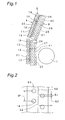
- Fig. 1 is a schematic sectional view of an air conditioner which uses a heat exchanger according to one embodiment of the invention.
- reference numeral 1 denotes a blower fan
- 2 denotes a heat exchanger.
- a casing or the like in which the blower fan 1 and the heat exchanger 2 are housed is omitted for simplicity's sake.
- This air conditioner is so designed that the blower fan 1 is rotated to blow out air, which serves as a heat transfer medium sucked in via the heat exchanger 2, through an unshown blowoff opening.
- the heat exchanger 2 has an auxiliary heat exchanger 8 as an example of a first heat exchanger section, and a main heat exchanger 9 as an example of a second heat exchanger section.
- the auxiliary heat exchanger 8 has sheet-like first fins 10, and unshown first heat transfer tubes.
- the first fin 10, as shown in Fig. 1, has a generally long-and-narrow rectangular-shaped surface.
- the first fin 10 is provided in plurality so as to be disposed at specified intervals along a thicknesswise direction of the first fin 10 (a direction perpendicular to the drawing sheet of Fig. 1).
- the first fin 10 is composed of a first portion 11 having a long-and-narrow rectangular-shaped surface, and a second portion 12 generally identical in shape to the first portion 11.
- first portion 11 In the first portion 11 are formed 1-row, 8-stage through holes 18 for insertion of heat transfer tubes.
- 1-row, 8-stage through holes 19 for insertion of heat transfer tubes are formed in the second portion 12.
- burrs 14 are formed at specified intervals on a longitudinal one-side edge of the first portion 11, while burrs 15 are formed at specified intervals on a longitudinal one-side edge of the second portion 12.
- the first heat transfer tubes are inserted into the 1-row, 8-stage through holes 18 of the first portion 11 for insertion of heat transfer tubes, as well as into the 1-row, 8-stage through holes 19 of the second portion 12 for insertion of heat transfer tubes. More specifically, the first heat transfer tubes are so placed as to run through a plurality of first fins 10 arrayed at specified intervals in a thicknesswise direction of the first fins.
- the second portion 12 is so positioned so as to adjoin the longitudinal one end of the first portion 11.
- the second portion 12 is so positioned as to be slightly inclined with respect to the first portion 11.
- the main heat exchanger 9 has sheet-like second fins 20 and unshown second heat transfer tubes.
- the second fin 20, as shown in Fig. 1, has a generally long-and-narrow rectangular-shaped surface.
- the second fin 20 is provided in plurality so as to be disposed at specified intervals along a thicknesswise direction of the second fin 20 (a direction perpendicular to the drawing sheet of Fig. 1).
- the second fin 20 is composed of a first portion 21 having a long-and-narrow rectangular-shaped surface, and a second portion 22 generally identical in shape to the first portion 21.
- first portion 21 In the first portion 21 are formed 2-row, 8-stage through holes 28 for insertion of heat transfer tubes.
- 2-row, 8-stage through holes 29 for insertion of heat transfer tubes are formed in the second portion 22.
- the first portion 21 of the second fin 20, the second portion 22 of the second fin 20, the first portion 11 of the first fin 10, and the second portion 12 of the first fin 10 are generally equal in longitudinal length to one another.
- the second portion 22 is so positioned as to adjoin longitudinal one end of the first portion 21. Also, the second portion 22 is so positioned as to be slightly inclined with respect to the first portion 21. One corner at longitudinal one end of the first portion 21 and one corner at longitudinal one end of the second portion 22 are in contact with each other.
- the second heat transfer tubes are inserted into the 2-row, 8-stage through holes 28 of the first portion 21 for insertion of heat transfer tubes, as well as into the 2-row, 8-stage through holes 29 of the second portion 22 for insertion of heat transfer tubes. More specifically, the second heat transfer tubes are so placed as to run through a plurality of second fins 20 arrayed at specified intervals in a thicknesswise direction of the second fins.
- one-side edges 26, 27 of the main heat exchanger 9, which is long and narrow and bent at one place, are so positioned as to be in contact with one-side edges 16, 17 of the long-and-narrow, bent-atone-place auxiliary heat exchanger 8 on one side on which the burrs 14, 15 are formed. More specifically, one edge 26 of the first portion 21 of the second fin 20 is in contact with the edge 16 of the first portion 11 of the first fin 10 on which the burrs 14 are present, while one edge 27 of the second portion 22 of the second fin 20 is in contact with the edge 17 of the second portion 12 of the first fin 10 on which the burrs 15 are present.
- edges 16, 17 having the burrs thereon are positioned inside, so that no burrs are present at outer-side edges of the heat exchanger. That is, burrs are present neither on an outer-side edge 30 of the first portion 11 of the first fin 10 nor on an outer-side edge 31 of the second portion 12 of the first fin 10. Also, burrs are present neither on an outer-side edge 40 of the first portion 21 of the second fin 20 nor on an outer-side edge 41 of the second portion 22 of the second fin 20.
- Fig. 2 is a view showing part of a perforated fin 50 used to form the first fin 10.
- reference numeral 18 denotes insertion holes for heat transfer tubes, and 52 denotes perforations (slits).
- Reference character DP denotes a distance between the through holes 18 adjacent to each other along a direction generally parallel to a direction in which the perforation extends, SL2 denotes a length of a perforation (slit), and SL1 denotes a connection part of the perforations.
- the perforated fin 50 is formed of a plate member having a generally rectangular-shaped surface.
- the perforations 52 are formed at a generally widthwise center of the perforated fin 50.
- the perforations 52 extend generally parallel to the longitudinal direction of the perforated fin 50.
- the first fin 10 shown in Fig. 1 is formed by dividing the perforated fin 50 at its portion where the perforations are formed. From the perforated fin 50 shown in Fig. 2, two first portions 11 of the first fin 10 are formed, or two second portions 12 of the first fin 10 are formed, or one first portion 11 and one second portion 12 of the first fin 10 are formed.
- Equation (1) There is a relationship shown by the following Equation (1) among DP, SL2 and SL1.
- the size of the connection part SL1 of the perforations is limited to a range shown by the following Equation (2). Limiting the size of the connection part SL1 of the perforations to the range shown by Equation (2) prevents the perforated fins from becoming lower in strength than a specified strength, and also allows the perforated fins to be easily divided at the perforation.
- SL ⁇ 2 DP - SL ⁇ 1 0.15 ( mm ) ⁇ SL ⁇ 1 ⁇ 0.5 mm
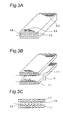
- Figs. 3A to 3C are views showing manufacturing process of the first portions 11 or the second portions 12 of the first fins shown in Fig. 1.
- a method for manufacturing the first portions 11 or the second portions 12 shown in Fig. 1 are described below with reference to Figs. 3A to 3C.
- reference numeral 50 denotes the perforated fin shown in Fig. 2.
- the heat transfer tube insertion holes 18 are actually disposed in a staggered arrangement as shown in Fig. 2, the insertion holes are disposed in a lattice arrangement for simplicity in Figs. 3A to 3C (actually, in a staggered arrangement).
- a plurality of above-described perforated fins 50 of the same configuration are disposed at equal intervals along the thicknesswise direction of the perforated fins 50 so that the perforated fins 50 are piled up.
- pins or other rod-like members (not shown) are inserted through some (two or more) of a plurality of heat transfer tube insertion holes 18 that are formed at the same positions of the plurality of piled-up perforated fins 50, so as to extend through the plurality of piled-up perforated fins 50.
- a force is applied along a direction shown by arrow ⁇ in Fig. 3B. More specifically, a force is applied in such a direction that two parts of the perforated fins 50 shown in Fig. 3A bordered by a line on which the perforations are formed are separated away from each other.
- This force is exerted, for example, by applying a force along the widthwise direction of the perforated fins 50 in such a way that one part on one side bordered by the perforations of the perforated fins 50 is fixed while the other part bordered by the perforations is separated from the above-mentioned one side.
- a force is applied to the perforated fins 50 in the direction shown by the arrow ⁇ in Fig. 3B so that the perforated fins 50 are divided into two by the line on which the perforations are formed as shown in Fig. 3B, by which the first portions 11 (or second portions 12) are formed.
- burrs 14 are formed at places of the first portions 11 corresponding to the connection parts of the perforations of the perforated fins 50 as shown in Fig. 3C.
- the edge of one fin with burrs present thereon is positioned so as to be in contact with or opposition to the edge of another fin, and that the edge with burrs present thereon is positioned inside, as in the heat exchanger of the embodiment shown in Fig. 1, such problems as scattering of condensed water or degradation of the appearance can be solved.
- the edges 16, 17 having the burrs 14, 15 present thereon and formed on one side of the first fins 10 are placed in contact with the edges 26, 27 of the second fins 20, and the edges 16, 17 having the burrs 14, 15 and formed in the heat exchanger are positioned inside. Therefore, the burrs 14, 15 are present only on the edges 16, 17 that are in contact with or opposition to the second fins 20, and not on the edges 30, 31, among the edges 16, 17, 30, 31 of the first fins 10, and moreover the burrs 14, 15 are present only on the edges 26, 27 that are in contact with or opposition to the first fins 10, and not on the edges 40, 41, among the edges 26, 27, 40, 41 of the second fins 20.
- the heat exchanger of the embodiment even when used as a heat exchanger on the indoor side of an air conditioner, can be kept from indoor scattering of the condensed water mixed in winds.
- the heat exchanger of this embodiment no burrs are present on the edges 30, 31 other than the edges 16, 17 that are in contact with or opposition to the second fins 20 among the edges 16, 17, 30, 31 of the first fins 10, and moreover no burrs are present on the edges 40, 41 other than the edges 26, 27 that are in contact with or opposition to the first fins 10 among the edges 26, 27, 40, 41 of the second fins 20. Therefore, the burrs 14, 15 having burrs present thereon are never positioned on the outer side of the heat exchanger. Thus, according to the heat exchanger of this embodiment, the appearance of the heat exchanger is not impaired.
- burrs are formed on the edges 16, 17 being in contact with the second fins 20 among the edges 16, 17, 30, 31 of the first fins 10.
- burrs may also be formed on edges of the first fins that are opposed to the second fins with a specified distance provided between the first fins and the second fins.
- burrs are formed only on the edges 16, 17 that are in contact with the second fins 20 among the edges 16, 17, 30, 31 of the first fins 10.
- burrs are formed on edges of the first fins that are in contact with or opposition to the second fins while burrs are formed on edges of the second fins that are in contact with or opposition to the first fins.
- burrs are formed only on edges of the second fins that are in contact with the first fins.
- 1-row, 16-stage insertion holes for heat transfer tubes are formed in the first fins 10, and moreover 2-row, 16-stage insertion holes are formed in the second fins 20.
- the arrangement of the insertion holes for heat transfer tubes to be formed in the first fins is not necessarily limited to the 1-row, 16-stage arrangement, and any arrangement may be adopted.
- the insertion holes for heat transfer tube to be formed in the second fins are not necessarily limited to the 2-row, 16-stage arrangement, and any arrangement may be adopted.
- the insertion holes 28 are provided in a staggered arrangement in the second fin 20.
- the insertion holes may be provided either in a staggered arrangement or in a lattice arrangement or in any other arrangement.
- the first fin 10 of the auxiliary heat exchanger 8 serving as the first heat exchanger section is composed of two portions, the first portion 11 and the second portion 12, while the second fin 20 of the main heat exchanger 9 serving as the second heat exchanger section is composed of two portions, the first portion 21 and the second portion 22.
- the first fin and the second fin is made up of one portion or three or more portions.
- auxiliary exchanger 8 and main heat exchanger 9 are so positioned that their edges are in contact with each other, and burrs are disposed on the inner side.
- burrs are formed only in the inner side.
Landscapes
- Engineering & Computer Science (AREA)
- Physics & Mathematics (AREA)
- Thermal Sciences (AREA)
- Mechanical Engineering (AREA)
- General Engineering & Computer Science (AREA)
- Chemical & Material Sciences (AREA)
- Combustion & Propulsion (AREA)
- Geometry (AREA)
- Air Filters, Heat-Exchange Apparatuses, And Housings Of Air-Conditioning Units (AREA)
- Devices For Blowing Cold Air, Devices For Blowing Warm Air, And Means For Preventing Water Condensation In Air Conditioning Units (AREA)
- Heat-Exchange Devices With Radiators And Conduit Assemblies (AREA)
Abstract
Description
- The present invention relates to a heat exchanger. More particularly, the invention relates to a heat exchanger suitable for use in air conditioners, refrigerators, ice makers and the like.
- Conventionally, there has been a heat exchanger formed by dividing perforated fins, which have perforations formed therein, at their perforations. More specifically, this heat exchanger is formed by inserting heat transfer tubes into insertion holes of a perforated fin and then separating the fin at the perforations so that two heat exchangers are formed.
- The conventional heat exchanger shown above, in which the fins can be separated at the places of the perforations, is easy to manufacture, having an advantage that heat exchangers of different dimensions can be easily manufactured by separating the fins at the perforations or not separating the fins at the perforations but leaving the perforations as they are.
- However, the above conventional heat exchanger, while having an advantage of easiness in changing dimensional settings of the fins, has a problem that because, in division of the fins, burrs are formed on an outer edge of the heat exchanger formed by dividing the perforated fins at the perforations and corresponding to places of the fins where the perforations have been separated, condensed water (dew drop water) generated on the fins during the use of the heat exchanger may scatter from the fins along the burrs. In particular, when the conventional heat exchanger is used as a heat exchanger on the indoor side of an air conditioner, the condensed water may be scattered indoors by air blows, giving rise to a serious problem.
- Further, in the conventional heat exchanger, since the edge on which the burrs are present is positioned at an outer edge of the heat exchanger, there is another problem that the appearance of the heat exchanger is impaired.
- Accordingly, an object of the present invention is to provide a heat exchanger which is easy to change in dimensional settings of its fins and which is less liable to scattering of condensed water from the fins and moreover which is kept from impairment of its appearance.
- In order to achieve the above object, the present invention provides a heat exchanger comprising:
- a first heat exchanger section having plate-shaped first fins, and a plurality of first heat transfer tubes inserted through the first fins so as to extend along a thicknesswise direction of the first fins; and
- a second heat exchanger section having plate-shaped second fins, and a plurality of second heat transfer tubes inserted through the second fins so as to extend along a thicknesswise direction of the second fins, wherein
- a plurality of burrs are present at specified intervals on edges of the first fins and/or the second fins, and
- the first heat exchanger section and the second heat exchanger section are so positioned that edges of the first fins or the second fins on which the burrs are present are in contact with or opposition to the other edges of the first fins or the second fins, where the edges having the burrs present thereon are positioned on an inner side.
- In the heat exchanger of this invention, edges with burrs present thereon in the first fins or the second fins are so positioned as to be in contact with or opposition to the other edges of the first fins or the second fins, and the edges with the burrs present thereon are positioned inside. Therefore, burrs are present only on the edges that are in contact with or opposition to the second fins, and not on the other edges, among all the edges of the first fins, and moreover burrs are present only on the edges that are in contact with or opposition to the first fins, and not on the other edges, among all the edges of the second fins.
- Consequently, even if condensed water has scattered from the edges having the burrs thereon, the scattered condensed water can be received by the edges that are in contact with or opposition to the edges having the burrs thereon. Thus, since condensed water can be prevented from scattering outside along with winds, the heat exchanger of the invention, even when used as a heat exchanger on the indoor side of an air conditioner, can be kept from indoor scattering of the condensed water mixed in winds.
- Also, in the heat exchanger of this invention, edges with burrs present thereon in the first fins or the second fins are so positioned as to be in contact with or opposition to the other edges of the first fins or the second fins, and the edges with the burrs present thereon are positioned inside. Therefore, burrs are present only on the edges that are in contact with or opposition to the second fins, and not on the other edges, among all the edges of the first fins, and moreover burrs are present only on the edges that are in contact with or opposition to the first fins, and not on the other edges, among all the edges of the second fins. Since the edges having the burrs thereon are never positioned on the outer side of the heat exchanger, the heat exchanger can be kept from impairment of its appearance.
- Also, in the heat exchanger of this invention, edges with burrs present thereon in the first fins or the second fins are so positioned as to be in contact with or opposition to the other edges of the first fins or the second fins, and the edges with the burrs present thereon are positioned inside. Therefore, even if condensed water has scattered from the edges having the burrs thereon, the scattered condensed water can be received by the edges that are in contact with or opposition to the edges having the burrs thereon. Thus, since condensed water can be prevented from scattering outside along with winds, the heat exchanger of the invention, even when used as a heat exchanger on the indoor side of an air conditioner, can be kept from indoor scattering of the condensed water mixed in winds.
- Further, in the heat exchanger of this invention, since the edges having the burrs thereon are never positioned on the outer side of the heat exchanger, the heat exchanger can be kept from impairment of its appearance.
- The present invention will become more fully understood from the detailed description given hereinbelow and the accompanying drawings which are given by way of illustration only, and thus are not intended to limit the present invention, and wherein:
- Fig. 1 is a schematic sectional view of an air conditioner which uses a heat exchanger according to one embodiment of the present invention;
- Fig. 2 is a view showing part of a perforated fin used to form a first fin included in the heat exchanger of the embodiment;
- Fig. 3A is a view showing manufacturing process of a first portion or a second portion of the first fins included in the heat exchanger of the embodiment;
- Fig. 3B is a view showing manufacturing process of a first portion or a second portion of the first fins included in the heat exchanger of the embodiment;
- Fig. 3C is a view showing manufacturing process of a first portion or a second portion of the first fins included in the heat exchanger of the embodiment;
- Hereinbelow, the present invention will be described in detail by embodiments thereof illustrated in the accompanying drawings.
- Fig. 1 is a schematic sectional view of an air conditioner which uses a heat exchanger according to one embodiment of the invention. In Fig. 1,
reference numeral 1 denotes a blower fan, and 2 denotes a heat exchanger. In Fig. 1, a casing or the like in which theblower fan 1 and theheat exchanger 2 are housed is omitted for simplicity's sake. - This air conditioner is so designed that the
blower fan 1 is rotated to blow out air, which serves as a heat transfer medium sucked in via theheat exchanger 2, through an unshown blowoff opening. - The
heat exchanger 2 has anauxiliary heat exchanger 8 as an example of a first heat exchanger section, and amain heat exchanger 9 as an example of a second heat exchanger section. - The
auxiliary heat exchanger 8 has sheet-likefirst fins 10, and unshown first heat transfer tubes. Thefirst fin 10, as shown in Fig. 1, has a generally long-and-narrow rectangular-shaped surface. Thefirst fin 10 is provided in plurality so as to be disposed at specified intervals along a thicknesswise direction of the first fin 10 (a direction perpendicular to the drawing sheet of Fig. 1). - The
first fin 10 is composed of afirst portion 11 having a long-and-narrow rectangular-shaped surface, and asecond portion 12 generally identical in shape to thefirst portion 11. In thefirst portion 11 are formed 1-row, 8-stage throughholes 18 for insertion of heat transfer tubes. Similarly, 1-row, 8-stage throughholes 19 for insertion of heat transfer tubes are formed in thesecond portion 12. Further,burrs 14 are formed at specified intervals on a longitudinal one-side edge of thefirst portion 11, whileburrs 15 are formed at specified intervals on a longitudinal one-side edge of thesecond portion 12. - The first heat transfer tubes are inserted into the 1-row, 8-stage through
holes 18 of thefirst portion 11 for insertion of heat transfer tubes, as well as into the 1-row, 8-stage throughholes 19 of thesecond portion 12 for insertion of heat transfer tubes. More specifically, the first heat transfer tubes are so placed as to run through a plurality offirst fins 10 arrayed at specified intervals in a thicknesswise direction of the first fins. - One corner at longitudinal one end of the
first portion 11 on which theburrs 14 are formed, and one corner at longitudinal one end of thesecond portion 12 on which theburrs 15 are formed, are in proximity to each other. Thesecond portion 12 is so positioned so as to adjoin the longitudinal one end of thefirst portion 11. Thesecond portion 12 is so positioned as to be slightly inclined with respect to thefirst portion 11. - The
main heat exchanger 9 has sheet-likesecond fins 20 and unshown second heat transfer tubes. Thesecond fin 20, as shown in Fig. 1, has a generally long-and-narrow rectangular-shaped surface. Thesecond fin 20 is provided in plurality so as to be disposed at specified intervals along a thicknesswise direction of the second fin 20 (a direction perpendicular to the drawing sheet of Fig. 1). - The
second fin 20 is composed of afirst portion 21 having a long-and-narrow rectangular-shaped surface, and asecond portion 22 generally identical in shape to thefirst portion 21. In thefirst portion 21 are formed 2-row, 8-stage throughholes 28 for insertion of heat transfer tubes. Similarly, 2-row, 8-stage throughholes 29 for insertion of heat transfer tubes are formed in thesecond portion 22. Thefirst portion 21 of thesecond fin 20, thesecond portion 22 of thesecond fin 20, thefirst portion 11 of thefirst fin 10, and thesecond portion 12 of thefirst fin 10 are generally equal in longitudinal length to one another. - The
second portion 22 is so positioned as to adjoin longitudinal one end of thefirst portion 21. Also, thesecond portion 22 is so positioned as to be slightly inclined with respect to thefirst portion 21. One corner at longitudinal one end of thefirst portion 21 and one corner at longitudinal one end of thesecond portion 22 are in contact with each other. - The second heat transfer tubes are inserted into the 2-row, 8-stage through
holes 28 of thefirst portion 21 for insertion of heat transfer tubes, as well as into the 2-row, 8-stage throughholes 29 of thesecond portion 22 for insertion of heat transfer tubes. More specifically, the second heat transfer tubes are so placed as to run through a plurality ofsecond fins 20 arrayed at specified intervals in a thicknesswise direction of the second fins. - Also, as shown in Fig. 1, one-
side edges main heat exchanger 9, which is long and narrow and bent at one place, are so positioned as to be in contact with one-side edges auxiliary heat exchanger 8 on one side on which theburrs edge 26 of thefirst portion 21 of thesecond fin 20 is in contact with theedge 16 of thefirst portion 11 of thefirst fin 10 on which theburrs 14 are present, while oneedge 27 of thesecond portion 22 of thesecond fin 20 is in contact with theedge 17 of thesecond portion 12 of thefirst fin 10 on which theburrs 15 are present. - The
edges side edge 30 of thefirst portion 11 of thefirst fin 10 nor on an outer-side edge 31 of thesecond portion 12 of thefirst fin 10. Also, burrs are present neither on an outer-side edge 40 of thefirst portion 21 of thesecond fin 20 nor on an outer-side edge 41 of thesecond portion 22 of thesecond fin 20. - Fig. 2 is a view showing part of a
perforated fin 50 used to form thefirst fin 10. - Referring to Fig. 2,
reference numeral 18 denotes insertion holes for heat transfer tubes, and 52 denotes perforations (slits). Reference character DP denotes a distance between the throughholes 18 adjacent to each other along a direction generally parallel to a direction in which the perforation extends, SL2 denotes a length of a perforation (slit), and SL1 denotes a connection part of the perforations. - The
perforated fin 50 is formed of a plate member having a generally rectangular-shaped surface. Theperforations 52 are formed at a generally widthwise center of theperforated fin 50. Theperforations 52 extend generally parallel to the longitudinal direction of theperforated fin 50. Thefirst fin 10 shown in Fig. 1 is formed by dividing theperforated fin 50 at its portion where the perforations are formed. From theperforated fin 50 shown in Fig. 2, twofirst portions 11 of thefirst fin 10 are formed, or twosecond portions 12 of thefirst fin 10 are formed, or onefirst portion 11 and onesecond portion 12 of thefirst fin 10 are formed. - There is a relationship shown by the following Equation (1) among DP, SL2 and SL1. The size of the connection part SL1 of the perforations is limited to a range shown by the following Equation (2). Limiting the size of the connection part SL1 of the perforations to the range shown by Equation (2) prevents the perforated fins from becoming lower in strength than a specified strength, and also allows the perforated fins to be easily divided at the perforation.


- Figs. 3A to 3C are views showing manufacturing process of the
first portions 11 or thesecond portions 12 of the first fins shown in Fig. 1. A method for manufacturing thefirst portions 11 or thesecond portions 12 shown in Fig. 1 are described below with reference to Figs. 3A to 3C. In Fig. 3A,reference numeral 50 denotes the perforated fin shown in Fig. 2. In theperforated fin 50, whereas the heat transfer tube insertion holes 18 are actually disposed in a staggered arrangement as shown in Fig. 2, the insertion holes are disposed in a lattice arrangement for simplicity in Figs. 3A to 3C (actually, in a staggered arrangement). - First, a plurality of above-described
perforated fins 50 of the same configuration are disposed at equal intervals along the thicknesswise direction of theperforated fins 50 so that theperforated fins 50 are piled up. Then, in this state, pins or other rod-like members (not shown) are inserted through some (two or more) of a plurality of heat transfer tube insertion holes 18 that are formed at the same positions of the plurality of piled-upperforated fins 50, so as to extend through the plurality of piled-upperforated fins 50. Thus, the state in which the plurality ofperforated fins 50 shown in Fig. 1 are piled up is maintained. - Next, a force is applied along a direction shown by arrow α in Fig. 3B. More specifically, a force is applied in such a direction that two parts of the
perforated fins 50 shown in Fig. 3A bordered by a line on which the perforations are formed are separated away from each other. This force is exerted, for example, by applying a force along the widthwise direction of theperforated fins 50 in such a way that one part on one side bordered by the perforations of theperforated fins 50 is fixed while the other part bordered by the perforations is separated from the above-mentioned one side. Then, a force is applied to theperforated fins 50 in the direction shown by the arrow α in Fig. 3B so that theperforated fins 50 are divided into two by the line on which the perforations are formed as shown in Fig. 3B, by which the first portions 11 (or second portions 12) are formed. - As a result of the formation of the
first portions 11 by such a method, the manufacturing cost for the first portions 11 (or second portions 12) can be reduced. Also, burrs 14 are formed at places of thefirst portions 11 corresponding to the connection parts of the perforations of theperforated fins 50 as shown in Fig. 3C. However, with an arrangement that the edge of one fin with burrs present thereon is positioned so as to be in contact with or opposition to the edge of another fin, and that the edge with burrs present thereon is positioned inside, as in the heat exchanger of the embodiment shown in Fig. 1, such problems as scattering of condensed water or degradation of the appearance can be solved. - In the heat exchanger of this embodiment, the
edges burrs first fins 10 are placed in contact with theedges second fins 20, and theedges burrs burrs edges second fins 20, and not on theedges edges first fins 10, and moreover theburrs edges first fins 10, and not on theedges 40, 41, among theedges second fins 20. - Consequently, even if condensed water has scattered from the
edges burrs edges edges burrs - Also, in the heat exchanger of this embodiment, no burrs are present on the
edges edges second fins 20 among theedges first fins 10, and moreover no burrs are present on theedges 40, 41 other than theedges first fins 10 among theedges second fins 20. Therefore, theburrs - In the heat exchanger of this embodiment, burrs are formed on the
edges second fins 20 among theedges first fins 10. However, in this invention, burrs may also be formed on edges of the first fins that are opposed to the second fins with a specified distance provided between the first fins and the second fins. - Also, in the heat exchanger of this embodiment, burrs are formed only on the
edges second fins 20 among theedges first fins 10. However, in this invention, it is also possible that burrs are formed on edges of the first fins that are in contact with or opposition to the second fins while burrs are formed on edges of the second fins that are in contact with or opposition to the first fins. Furthermore, it is also possible that burrs are formed only on edges of the second fins that are in contact with the first fins. - Also, in the heat exchanger of this embodiment, 1-row, 16-stage insertion holes for heat transfer tubes are formed in the
first fins 10, and moreover 2-row, 16-stage insertion holes are formed in thesecond fins 20. However, in this invention, the arrangement of the insertion holes for heat transfer tubes to be formed in the first fins is not necessarily limited to the 1-row, 16-stage arrangement, and any arrangement may be adopted. Similarly, the insertion holes for heat transfer tube to be formed in the second fins are not necessarily limited to the 2-row, 16-stage arrangement, and any arrangement may be adopted. - Also, in the heat exchanger of this embodiment, the insertion holes 28 are provided in a staggered arrangement in the
second fin 20. However, in the fins of this invention, the insertion holes may be provided either in a staggered arrangement or in a lattice arrangement or in any other arrangement. - Further, in the heat exchanger of this embodiment, the
first fin 10 of theauxiliary heat exchanger 8 serving as the first heat exchanger section is composed of two portions, thefirst portion 11 and thesecond portion 12, while thesecond fin 20 of themain heat exchanger 9 serving as the second heat exchanger section is composed of two portions, thefirst portion 21 and thesecond portion 22. However, for this invention, it is also possible that at least one of the first fin and the second fin is made up of one portion or three or more portions. - Further, in the heat exchanger of this embodiment, two heat exchanger sections (
auxiliary exchanger 8 and main heat exchanger 9) are so positioned that their edges are in contact with each other, and burrs are disposed on the inner side. However, in this invention, it is of course possible that three or more heat exchanger sections are positioned so that edges of adjacent heat exchanger sections are in contact with or opposition to each other, where burrs are formed only in the inner side. - Embodiments of the invention being thus described, it will be obvious that the same may be varied in many ways. Such variations are not to be regarded as a departure from the spirit and scope of the invention, and all such modifications as would be obvious to one skilled in the art are intended to be included within the scope of the following claims.
Claims (1)
- A heat exchanger comprising:a first heat exchanger section (8) having plate-shaped first fins (10), and a plurality of first heat transfer tubes inserted through the first fins (10) so as to extend along a thicknesswise direction of the first fins (10); anda second heat exchanger section (9) having plate-shaped second fins (20), and a plurality of second heat transfer tubes inserted through the second fins (20) so as to extend along a thicknesswise direction of the second fins (20), whereina plurality of burrs (14, 15) are present at specified intervals on edges (16, 17) of the first fins (10) and/or the second fins (20), andthe first heat exchanger section (8) and the second heat exchanger section (9) are so positioned that edges (16, 17) of the first fins (10) or the second fins (20) on which the burrs (14, 15) are present are in contact with or opposition to the other edges (26, 27) of the first fins (10) or the second fins (20), where the edges (16, 17) having the burrs (14, 15) present thereon are positioned on an inner side.
Applications Claiming Priority (2)
| Application Number | Priority Date | Filing Date | Title |
|---|---|---|---|
| JP2004340326A JP3852464B2 (en) | 2004-11-25 | 2004-11-25 | Heat exchanger inside the air conditioner |
| PCT/JP2005/021420 WO2006057233A1 (en) | 2004-11-25 | 2005-11-22 | Heat exchanger |
Publications (2)
| Publication Number | Publication Date |
|---|---|
| EP1821049A1 true EP1821049A1 (en) | 2007-08-22 |
| EP1821049A4 EP1821049A4 (en) | 2014-01-01 |
Family
ID=36497970
Family Applications (1)
| Application Number | Title | Priority Date | Filing Date |
|---|---|---|---|
| EP05809549.8A Withdrawn EP1821049A4 (en) | 2004-11-25 | 2005-11-22 | HEAT EXCHANGER |
Country Status (6)
| Country | Link |
|---|---|
| US (1) | US9086245B2 (en) |
| EP (1) | EP1821049A4 (en) |
| JP (1) | JP3852464B2 (en) |
| CN (1) | CN100470172C (en) |
| AU (1) | AU2005308184B2 (en) |
| WO (1) | WO2006057233A1 (en) |
Cited By (3)
| Publication number | Priority date | Publication date | Assignee | Title |
|---|---|---|---|---|
| CN104246409A (en) * | 2012-04-23 | 2014-12-24 | 松下知识产权经营株式会社 | Fnned tube heat exchanger |
| EP2835587A4 (en) * | 2012-03-26 | 2015-10-14 | Daikin Ind Ltd | HEAT EXCHANGER FOR AIR CONDITIONING DEVICE AND AIR CONDITIONING DEVICE |
| CN106062500A (en) * | 2014-02-28 | 2016-10-26 | 电装国际美国公司 | Insert for heat exchanger and heat exchanger having the same |
Families Citing this family (6)
| Publication number | Priority date | Publication date | Assignee | Title |
|---|---|---|---|---|
| US9303882B2 (en) * | 2009-06-26 | 2016-04-05 | Trane International Inc. | Blow through air handler |
| JP2014040983A (en) * | 2012-08-23 | 2014-03-06 | Daikin Ind Ltd | Heat exchanger of air conditioning apparatus |
| CN104896985B (en) * | 2015-06-11 | 2017-03-08 | 广东美的制冷设备有限公司 | Finned heat exchanger for air-conditioner |
| WO2017006433A1 (en) * | 2015-07-07 | 2017-01-12 | 三菱電機株式会社 | Heat exchanger, refrigeration cycle device, and method for manufacturing heat exchanger |
| CN110410864B (en) * | 2019-07-31 | 2021-12-21 | 广东美的制冷设备有限公司 | Electric heater for cabinet air conditioner and cabinet air conditioner with electric heater |
| US12044431B2 (en) | 2020-11-16 | 2024-07-23 | Cody Martin | Enclosures for air systems, air systems having enclosures, and methods of using enclosures |
Family Cites Families (14)
| Publication number | Priority date | Publication date | Assignee | Title |
|---|---|---|---|---|
| US4173998A (en) * | 1978-02-16 | 1979-11-13 | Carrier Corporation | Formed coil assembly |
| US4877087A (en) * | 1984-08-16 | 1989-10-31 | Sundstrand Heat Transfer, Inc. | Segmented fin heat exchanger core |
| FR2645633B1 (en) * | 1989-04-07 | 1991-07-12 | Chaffoteaux Et Maury | IMPROVEMENTS ON DOUBLE PIPES FOR MIXED BOILERS, PROCESSES FOR MANUFACTURING SUCH PIPES AND CORRESPONDING BOILERS |
| JP3071307B2 (en) * | 1992-06-12 | 2000-07-31 | 東芝キヤリア株式会社 | Air conditioner |
| JP3272457B2 (en) * | 1993-03-05 | 2002-04-08 | 三菱重工業株式会社 | Plate fin and tube heat exchanger |
| JPH06347186A (en) * | 1993-06-07 | 1994-12-20 | Matsushita Refrig Co Ltd | Manufacture of heat exchanger fin and heat exchanger |
| JP3312986B2 (en) * | 1994-02-25 | 2002-08-12 | 東芝キヤリア株式会社 | Heat exchanger and method of manufacturing heat exchanger |
| JP3292077B2 (en) * | 1997-01-30 | 2002-06-17 | 株式会社日立製作所 | Heat exchangers and air conditioners |
| ES2196294T3 (en) * | 1997-12-30 | 2003-12-16 | Carrier Corp | MULTIPLE ROW HEAT EXCHANGER. |
| US6273182B1 (en) * | 2000-05-19 | 2001-08-14 | Delphi Technologies, Inc. | Heat exchanger mounting |
| US20030102112A1 (en) * | 2001-12-03 | 2003-06-05 | Smithey David W. | Flattened tube heat exchanger made from micro-channel tubing |
| JP3984843B2 (en) * | 2002-03-19 | 2007-10-03 | 日立アプライアンス株式会社 | Manufacturing method of heat exchanger |
| US6672375B1 (en) * | 2002-07-02 | 2004-01-06 | American Standard International Inc. | Fin tube heat exchanger with divergent tube rows |
| JP5756673B2 (en) * | 2011-04-27 | 2015-07-29 | 日立コンシューマエレクトロニクス株式会社 | Recording / playback device |
-
2004
- 2004-11-25 JP JP2004340326A patent/JP3852464B2/en not_active Expired - Fee Related
-
2005
- 2005-11-22 US US11/791,540 patent/US9086245B2/en not_active Expired - Fee Related
- 2005-11-22 CN CNB2005800403425A patent/CN100470172C/en not_active Expired - Fee Related
- 2005-11-22 WO PCT/JP2005/021420 patent/WO2006057233A1/en not_active Ceased
- 2005-11-22 EP EP05809549.8A patent/EP1821049A4/en not_active Withdrawn
- 2005-11-22 AU AU2005308184A patent/AU2005308184B2/en not_active Ceased
Cited By (5)
| Publication number | Priority date | Publication date | Assignee | Title |
|---|---|---|---|---|
| EP2835587A4 (en) * | 2012-03-26 | 2015-10-14 | Daikin Ind Ltd | HEAT EXCHANGER FOR AIR CONDITIONING DEVICE AND AIR CONDITIONING DEVICE |
| US9328965B2 (en) | 2012-03-26 | 2016-05-03 | Daikin Industries, Ltd. | Heat exchanger of air conditioning device including a refrigerant path arranged downstream of other refrigerant paths relative to airflow direction |
| CN104246409A (en) * | 2012-04-23 | 2014-12-24 | 松下知识产权经营株式会社 | Fnned tube heat exchanger |
| CN106062500A (en) * | 2014-02-28 | 2016-10-26 | 电装国际美国公司 | Insert for heat exchanger and heat exchanger having the same |
| CN106062500B (en) * | 2014-02-28 | 2018-07-27 | 电装国际美国公司 | Insertion section for heat exchanger and the heat exchanger with the insertion section |
Also Published As
| Publication number | Publication date |
|---|---|
| JP3852464B2 (en) | 2006-11-29 |
| EP1821049A4 (en) | 2014-01-01 |
| AU2005308184B2 (en) | 2009-04-23 |
| US20080006397A1 (en) | 2008-01-10 |
| WO2006057233A1 (en) | 2006-06-01 |
| AU2005308184A1 (en) | 2006-06-01 |
| CN100470172C (en) | 2009-03-18 |
| JP2006153291A (en) | 2006-06-15 |
| CN101065625A (en) | 2007-10-31 |
| US9086245B2 (en) | 2015-07-21 |
Similar Documents
| Publication | Publication Date | Title |
|---|---|---|
| US6050328A (en) | Heat exchanger and air conditioner using same | |
| EP2869016B1 (en) | Heat exchanger, method for manufacturing heat exchanger, and air conditioner | |
| CN103299150B (en) | Heat exchanger and air conditioner | |
| CN102322762B (en) | Heat exchanger, air conditioner and method for manufacturing heat exchanger | |
| CN102272547A (en) | Fin for a heat exchanger, and heat exchanger including such a fin | |
| US9086245B2 (en) | Heat exchanger | |
| US6598295B1 (en) | Plate-fin and tube heat exchanger with a dog-bone and serpentine tube insertion method | |
| EP1528346A2 (en) | fin and heat exchanger | |
| EP1906129A1 (en) | Fin tube heat exchanger | |
| EP1486748A1 (en) | Heat exchanger, heat exchanger manufacturing method, and air conditioner | |
| US20190120557A1 (en) | Heat exchanger | |
| CN205980897U (en) | Heat exchangers, heating and cooling equipment, and refrigerators | |
| JP2004116845A (en) | Heat exchanger and its manufacturing method | |
| JP2006038311A (en) | Finned tube heat exchanger | |
| CN106642642A (en) | Finned tube type heat exchanger and air conditioner with same | |
| JP2002071289A (en) | Heat exchanger for air conditioner | |
| EP1830150A1 (en) | Heat exchanger | |
| JP5899413B2 (en) | Manufacturing method of heat exchanger | |
| WO2013018297A1 (en) | Heat exchanger | |
| JPH0886581A (en) | Cross fin tube type heat exchanger | |
| JP2003014388A (en) | Heat exchanger and its manufacturing method | |
| JPH0534470U (en) | Plate fins for air conditioning heat exchangers | |
| JP2003343878A (en) | Air conditioner | |
| JPS6093295A (en) | Side plate for heat exchanger | |
| JP2011085341A (en) | Air conditioner |
Legal Events
| Date | Code | Title | Description |
|---|---|---|---|
| PUAI | Public reference made under article 153(3) epc to a published international application that has entered the european phase |
Free format text: ORIGINAL CODE: 0009012 |
|
| 17P | Request for examination filed |
Effective date: 20070606 |
|
| AK | Designated contracting states |
Kind code of ref document: A1 Designated state(s): AT BE BG CH CY CZ DE DK EE ES FI FR GB GR HU IE IS IT LI LT LU LV MC NL PL PT RO SE SI SK TR |
|
| RIN1 | Information on inventor provided before grant (corrected) |
Inventor name: TAIRA, SHIGEHARUC/O SHIGA PLANT OF DAIKIN INDUSTRI Inventor name: KITAZAWA, MASAAKIC/O SHIGA PLANT OF DAIKIN INDUSTR |
|
| DAX | Request for extension of the european patent (deleted) | ||
| A4 | Supplementary search report drawn up and despatched |
Effective date: 20131202 |
|
| RIC1 | Information provided on ipc code assigned before grant |
Ipc: F25B 39/02 20060101AFI20131126BHEP Ipc: F28F 1/32 20060101ALI20131126BHEP Ipc: F24F 1/00 20110101ALI20131126BHEP |
|
| 17Q | First examination report despatched |
Effective date: 20150616 |
|
| GRAP | Despatch of communication of intention to grant a patent |
Free format text: ORIGINAL CODE: EPIDOSNIGR1 |
|
| RIC1 | Information provided on ipc code assigned before grant |
Ipc: F25B 39/02 20060101AFI20190118BHEP Ipc: F28F 1/32 20060101ALI20190118BHEP Ipc: F28F 17/00 20060101ALI20190118BHEP Ipc: F24F 1/00 20190101ALI20190118BHEP |
|
| INTG | Intention to grant announced |
Effective date: 20190211 |
|
| STAA | Information on the status of an ep patent application or granted ep patent |
Free format text: STATUS: THE APPLICATION IS DEEMED TO BE WITHDRAWN |
|
| 18D | Application deemed to be withdrawn |
Effective date: 20190622 |