EP1820944A2 - Supercore sump vent pressure control - Google Patents
Supercore sump vent pressure control Download PDFInfo
- Publication number
- EP1820944A2 EP1820944A2 EP07101940A EP07101940A EP1820944A2 EP 1820944 A2 EP1820944 A2 EP 1820944A2 EP 07101940 A EP07101940 A EP 07101940A EP 07101940 A EP07101940 A EP 07101940A EP 1820944 A2 EP1820944 A2 EP 1820944A2
- Authority
- EP
- European Patent Office
- Prior art keywords
- sump
- cavity
- air
- flow communication
- flow
- Prior art date
- Legal status (The legal status is an assumption and is not a legal conclusion. Google has not performed a legal analysis and makes no representation as to the accuracy of the status listed.)
- Granted
Links
- 238000000034 method Methods 0.000 claims abstract description 9
- 238000013022 venting Methods 0.000 claims abstract description 5
- 238000004891 communication Methods 0.000 claims description 33
- 230000000712 assembly Effects 0.000 claims description 10
- 238000000429 assembly Methods 0.000 claims description 10
- 230000003213 activating effect Effects 0.000 claims 1
- 230000001419 dependent effect Effects 0.000 claims 1
- 230000000415 inactivating effect Effects 0.000 claims 1
- 239000003921 oil Substances 0.000 description 51
- 239000010687 lubricating oil Substances 0.000 description 5
- 238000005461 lubrication Methods 0.000 description 5
- 239000000203 mixture Substances 0.000 description 5
- 238000010586 diagram Methods 0.000 description 4
- 238000001816 cooling Methods 0.000 description 2
- 238000004140 cleaning Methods 0.000 description 1
- 238000012986 modification Methods 0.000 description 1
- 230000004048 modification Effects 0.000 description 1
- 239000007858 starting material Substances 0.000 description 1
Images



Classifications
-
- F—MECHANICAL ENGINEERING; LIGHTING; HEATING; WEAPONS; BLASTING
- F01—MACHINES OR ENGINES IN GENERAL; ENGINE PLANTS IN GENERAL; STEAM ENGINES
- F01D—NON-POSITIVE DISPLACEMENT MACHINES OR ENGINES, e.g. STEAM TURBINES
- F01D25/00—Component parts, details, or accessories, not provided for in, or of interest apart from, other groups
- F01D25/08—Cooling; Heating; Heat-insulation
- F01D25/12—Cooling
- F01D25/125—Cooling of bearings
-
- F—MECHANICAL ENGINEERING; LIGHTING; HEATING; WEAPONS; BLASTING
- F01—MACHINES OR ENGINES IN GENERAL; ENGINE PLANTS IN GENERAL; STEAM ENGINES
- F01D—NON-POSITIVE DISPLACEMENT MACHINES OR ENGINES, e.g. STEAM TURBINES
- F01D25/00—Component parts, details, or accessories, not provided for in, or of interest apart from, other groups
- F01D25/18—Lubricating arrangements
- F01D25/20—Lubricating arrangements using lubrication pumps
-
- F—MECHANICAL ENGINEERING; LIGHTING; HEATING; WEAPONS; BLASTING
- F02—COMBUSTION ENGINES; HOT-GAS OR COMBUSTION-PRODUCT ENGINE PLANTS
- F02C—GAS-TURBINE PLANTS; AIR INTAKES FOR JET-PROPULSION PLANTS; CONTROLLING FUEL SUPPLY IN AIR-BREATHING JET-PROPULSION PLANTS
- F02C7/00—Features, components parts, details or accessories, not provided for in, or of interest apart form groups F02C1/00 - F02C6/00; Air intakes for jet-propulsion plants
- F02C7/06—Arrangements of bearings; Lubricating
-
- F—MECHANICAL ENGINEERING; LIGHTING; HEATING; WEAPONS; BLASTING
- F05—INDEXING SCHEMES RELATING TO ENGINES OR PUMPS IN VARIOUS SUBCLASSES OF CLASSES F01-F04
- F05D—INDEXING SCHEME FOR ASPECTS RELATING TO NON-POSITIVE-DISPLACEMENT MACHINES OR ENGINES, GAS-TURBINES OR JET-PROPULSION PLANTS
- F05D2240/00—Components
- F05D2240/50—Bearings
-
- Y—GENERAL TAGGING OF NEW TECHNOLOGICAL DEVELOPMENTS; GENERAL TAGGING OF CROSS-SECTIONAL TECHNOLOGIES SPANNING OVER SEVERAL SECTIONS OF THE IPC; TECHNICAL SUBJECTS COVERED BY FORMER USPC CROSS-REFERENCE ART COLLECTIONS [XRACs] AND DIGESTS
- Y02—TECHNOLOGIES OR APPLICATIONS FOR MITIGATION OR ADAPTATION AGAINST CLIMATE CHANGE
- Y02T—CLIMATE CHANGE MITIGATION TECHNOLOGIES RELATED TO TRANSPORTATION
- Y02T50/00—Aeronautics or air transport
- Y02T50/60—Efficient propulsion technologies, e.g. for aircraft
Definitions
- This invention relates generally to gas turbine engines, and, more particularly, to control of air pressure within a bearing oil sump during all operating conditions.
- a gas turbine engine typically includes at least one bearing assembly that supports a rotatable shaft.
- Each bearing assembly is housed within a sump to which lubricating oil is supplied from a supply pump and from which lubricating oil is scavenged and passed through an oil/air separator and a heat exchange system for cleaning and cooling before being returned to the lubricating oil supply system.
- some gas turbine engines employ bearing sumps housed within pressurized cavities sealed with circumferential labyrinth seals and supplied with air under pressure to minimize oil leakage.
- Certain aero-derivative gas turbine engines such as the LMS100, sold by the assignee of this case, require vent sump pressure control to prevent escape of lubricating oil from an oil sump and to prevent oil consumption when operating at high power and corresponding high inlet pressure.
- a sump evacuation system is employed to lower air pressure inside a sump pressurization cavity to prevent oil leakage during low power or idle operation. As the power levels of gas turbines has been raised, a system to control oil leakage at high power is needed.
- Various aspects of the invention relate to methods and apparatus for controlling sump pressurization in a gas turbine bearing sump by controllably restricting or actively venting air flow from said sump cavity to maintain a continuous air flow from said sump cavity through a sump vent in all operating conditions.
- FIG. 1 is a schematic illustration of a gas turbine engine 10, including a low pressure compressor 12, a high pressure compressor 14, a combustor 16, a high pressure turbine 18, and a low pressure turbine 20.
- Low pressure compressor 12 is connected to low pressure turbine 20 by a first shaft 24, and high pressure compressor 14 is connected to high pressure turbine 18 by a second shaft 22.
- a plurality of bearing assemblies rotatably support first shaft 24 and second shaft 22 for concentric rotation around longitudinal axis 26.
- Each bearing assembly is contained within an oil sump. Controlling air pressure within each oil sump aids in maintaining adequate bearing lubrication during all rotational speeds, from sub-idle to maximum power.
- "Idle” is defined as the lowest rotational operating speed range at which a gas turbine engine operates in a stable mode.
- “idle” speed for the LMS100 engine is a rotational speed in the range between approximately 6000 and 7000 rpm and in other gas turbine engines may range between about 2500 and 6500 rpm.
- “Sub-idle” is an engine rotational speed below idle or below the minimum rotational speed at which the engine can sustain stable operation on its own and requires a starter motor to maintain rotation, used for example, for cooling the engine and for engine check out before ignition.
- Maximum power is the highest speed and highest power output, in the LMS100 approximately 10,400 to 10,600 rpm.
- Each oil sump is vented via a respective sump vent tube 34, 36 and 38, via air tubes 40 and 42, controlled by respective adjustable valves 35, 37, 39 connecting respective oil sumps to a pressure control system 30 driven by a gear box 32.
- Each of valves 35, 37 and 39 may be individually activated to a setting appropriate to provide control of air flow through respective sump vent tubes 34, 36 and 38 and minimize oil consumption.
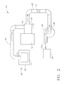
- FIG. 2 is a schematic illustration of a sump evacuation system 90 used with lubrication system 28, including a sump oil cavity 44 pressurized by air flow from an oil pressurization cavity 80.
- Cavity sump vent 70 is connected by vent tube 82 to intake 95 of air/oil separator 92 driven by an accessory drive or gear box 32.
- Air/oil separator 92 receives a mixture of air and entrained lubricating oil from each sump oil cavity 44.
- Separator exhaust 96 is coupled to intake 98 of blower 94 via pipe 93 incorporating adjustable valve 91.
- Blower 94 exhausts air at output 100 to a vent system 102, which may be incorporated into the engine exhaust gas flow.
- adjustable valve 91 is set to its open position and blower 94 is turned on to maintain a positive pressure on labyrinth seals to minimize oil leakage.
- adjustable valve 91 is set to a partially closed position and blower 94 is turned off to allow air flow into the air/oil separator 92 to be driven by pressurized air flow.
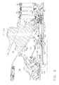
- FIGS 3, 4 and 5 schematically illustrate an exemplary bearing assembly sump vent pressure control system.
- Bearing assemblies 110, 120 and 130 rotatably support rotor shaft 141.
- Booster output 54 is connected in flow communication through passages within strut 134 and opening 135 with air cavity 140 which is connected through opening 136 and duct 142 to sump pressurization cavity 138.
- Sump pressurization cavity 138 is in flow communication with a sump cavity chamber 114 via labyrinth seal 146 and is sealed by labyrinth seal 148 to minimize oil consumption by leakage, shown by arrow 149, into engine interior cavity 150 exterior to sump pressurization cavity 138.
- Bearing assembly 110 is surrounded by a sump cavity 112 comprising sump cavity chamber 114 in flow communication through opening 115 with sump cavity chamber 116 which is also in flow communication through opening 117 with sump cavity chamber 118.
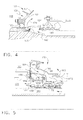
- Bearing assembly 120 is surrounded by a sump cavity 122 comprising sump cavity chambers 118 and 124 in flow communication through opening 152 through chamber wall 154, as shown enlarged in Figure 4.
- Bearing assembly 130 is surrounded by a sump cavity 132, comprising sump cavity chambers 126 and 128 in flow communication through opening 184 through housing wall 186, as shown enlarged in Figure 5.
- Booster air flow passages through strut 134 are in flow communication through opening 162 with air cavity 160 and through opening 164 with sump pressurization cavity 166.
- Sump pressurization cavity 166 is sealed from leakage into engine turbine interior cavity 168 as shown by arrow 165 by labyrinth seal 170 and is connected in flow communication with sump cavity chamber 128 through labyrinth seal 172.
- Sump pressurization cavity 166 supplies pressurized air as shown by arrow 177 through opening 178 into sump pressurization cavity 180 which directs pressurized air flow to labyrinth seal 176, as shown by arrow 182.
- sump cavity 112 is pressurized by compressed air from engine booster output 54 supplied through passages within strut 134 through opening 135, shown by arrow 133, into air cavity 140, and through opening 136, shown by arrow 137, and duct 142 along the sump wall 144 of forward sump cavity chamber 116 and air cavity 140 into sump pressurization cavity 138, as shown by arrow 145.
- Compressed air flows through labyrinth seal 146, as shown by arrow 147, into sump cavity chamber 114, into sump cavity chamber 116 through opening 115, as shown by arrow 113, and through opening 117 into sump cavity chamber 118, as shown by arrow 119.
- Sump cavity 122 is pressurized by the air flow into sump cavity chamber 118 and via opening 152 through chamber wall 154, as shown by arrow 151, into sump cavity chamber 124. Pressurized air flow through sump pressurization cavity 180 as shown by arrow 182 also enters sump cavity chamber 124 through labyrinth seal 176, as shown by arrow 179, as shown in Figure 4.
- Booster air flow shown by arrow 55, through passages within strut 134 through opening 162 as shown by arrow 161 pressurizes air cavity 160 and through opening 164, as shown by arrow 188, pressurizes sump pressurization cavity 166.
- Air flow from sump pressurization cavity 166 provides pressurized air to sump cavity chamber 128 through labyrinth seal 172, as shown by arrow 174, as shown in Figure 5.
- Sump pressurization cavity 166 supplies pressurized air as shown by arrow 177 through opening 178 via sump pressurization cavity 180 which is connected in flow communication with sump cavity chamber 124 via labyrinth seal 176, as shown by arrow 179, and through opening 184 as shown by arrow 190 into sump cavity chamber 126.
- Sump cavity chamber 126 is vented to sump cavity chamber 124 as shown by arrow 192.
- Figure 6 illustrates in block diagram form the active control scheme used to control pressurization of the sump cavities 112, 122, 132 in order to avoid oil consumption, during all above idle rotational speeds.
- Air pressure provided by air flow from booster 54 raises air pressure within sump pressurization cavities 138, 166 and 180, and will force a mixture of air with entrained oil to flow through sump cavities 112, 122 and 132 to sump cavity chamber 124 and sump vent tube 200 to the air/oil separator 92.
- Air/oil separator 92 removes oil from the mixture and returns it to oil tank 86 and oil sump cavities 112, 122 and 132.
- Pressure inside the sump cavities 112, 122, and 132 will typically be between 18 and 24 psia (pounds per square inch absolute) at maximum power driven by air flow through labyrinth seals 146, 176 and 172, which would be pressurized to approximately 42 psia in sump pressurization cavity 138 and 33 psia in sump pressurization cavities 166 and 180, as shown in Figure 6.
- These increased air pressures may tend to accelerate air flow through sump cavities 112, 122 and 132 and increase the quantity of entrained oil flowing to air/oil separator 92. Avoiding excessive oil consumption would require a large capacity air/oil separator and oil tank adding significant size and weight to the engine system.
- adjustable valve 91 is set to a partially closed position and blower 94 is turned off. This holds air pressure within sump cavity chamber 124 at approximately 24.7 psi guage and restricts air and oil flow to an quantity which can be readily processed by air/oil separator 92 to remove oil and deposit it into oil tank 86 for recirculation to bearing assemblies 110, 120 and 130.
- Figure 7 illustrates in block diagram form the active control scheme used to control pressurization of the sump cavities 112, 122, 132 when a gas turbine engine is operating at idle or sub-idle.
- Air pressure within sump pressurization cavities 138, 166 and 180 is approximately atmospheric pressure as shown and is inadequate to maintain continuous flow from the sump cavities 112, 122, 132 through sump vent tube 200 to air/oil separator 92.
- adjustable valve 91 is set to a fully open position and blower 94 is turned on.
- Blower 94 draws air flow through the vent tube to lower pressure inside the sump cavities 112, 122, and 132 to approximately 14.0 psi. and draw an air-oil mixture to the air/oil separator 92 which removes the oil from the mixture which is returned to the oil sump cavities 112, 122 and 132 through oil tank 86.
- FIGs 3, 6 and 7 illustrate schematically a system having three sump cavities 112, 122, and 132, but it is to be understood that the oil sump pressurization system described can be employed to control pressurization of a single sump cavity surrounding a single bearing assembly or a large number of bearing assemblies, or can be used with a plurality of separate vent tubes including a separately controlled valves connected individually to separate bearing assemblies, so that each may be individually controlled.
- Figure 1 illustrates an sump lubrication system in which air flow through sump vent tubes 34, 36 and 38 is separately controlled by respective adjustable valves 35, 37 and 39.
- Each of adjustable valves 35, 37 and 39 may be set to a unique setting to restrict flow in each respective sump vent tube 34, 36 and 38 at a separate flow rate from the other flow tubes to allow a predetermined air flow through the respective sump vent tubes 34, 36 and 38 to maintain oil/air flow into the air/oil separator during all operating conditions. Certain operating conditions may require that one of the adjustable valves 35, 37 or 39 be set to a restricted flow setting with the blower turned off, while allowing another adjustable valve to be set at its fully open position with its blower turned on.
- the flexibility of pressure control provided by the controllable blower and valve combination to each bearing assembly or combination of bearing assemblies offers maximum protection to the bearing assembly lubrication system.
Landscapes
- Engineering & Computer Science (AREA)
- Mechanical Engineering (AREA)
- General Engineering & Computer Science (AREA)
- Chemical & Material Sciences (AREA)
- Combustion & Propulsion (AREA)
- Turbine Rotor Nozzle Sealing (AREA)
- Supercharger (AREA)
- Sealing Using Fluids, Sealing Without Contact, And Removal Of Oil (AREA)
- Magnetic Bearings And Hydrostatic Bearings (AREA)
Abstract
Description
- This invention relates generally to gas turbine engines, and, more particularly, to control of air pressure within a bearing oil sump during all operating conditions.
- A gas turbine engine typically includes at least one bearing assembly that supports a rotatable shaft. Each bearing assembly is housed within a sump to which lubricating oil is supplied from a supply pump and from which lubricating oil is scavenged and passed through an oil/air separator and a heat exchange system for cleaning and cooling before being returned to the lubricating oil supply system. To control oil leakage from the sump, some gas turbine engines employ bearing sumps housed within pressurized cavities sealed with circumferential labyrinth seals and supplied with air under pressure to minimize oil leakage. Certain aero-derivative gas turbine engines, such as the LMS100, sold by the assignee of this case, require vent sump pressure control to prevent escape of lubricating oil from an oil sump and to prevent oil consumption when operating at high power and corresponding high inlet pressure.
- In some prior art gas turbine engines, as shown, for example, in
United States Patent 6,470,666 B1, issued October 29, 2002 to Przytulski et al. and assigned to the assignee of the present case, a sump evacuation system is employed to lower air pressure inside a sump pressurization cavity to prevent oil leakage during low power or idle operation. As the power levels of gas turbines has been raised, a system to control oil leakage at high power is needed. - Various aspects of the invention relate to methods and apparatus for controlling sump pressurization in a gas turbine bearing sump by controllably restricting or actively venting air flow from said sump cavity to maintain a continuous air flow from said sump cavity through a sump vent in all operating conditions.
- Various aspects and embodiments of the present invention will now be described in connection with the accompanying drawings, in which:
- Figure 1 is a schematic illustration of an exemplary gas turbine engine having a sump evacuation system;
- Figure 2 is a schematic illustration of an exemplary sump evacuation apparatus;
- Figure 3 is a schematic cross-sectional view of an exemplary sump vent pressure control system for a gas turbine engine;
- Figure 4 is a schematic, enlarged, cross-sectional view of one exemplary bearing sump incorporating a vent pressure control system;
- Figure 5 is a schematic, enlarged, cross-sectional view of a second exemplary bearing sump incorporating a vent pressure control scheme;
- Figure 6 is a block diagram illustration of a first exemplary operation of a sump vent pressure control system; and
- Figure 7 is a block diagram illustration of a second exemplary operation of a sump vent pressure control system.
- Figure 1 is a schematic illustration of a
gas turbine engine 10, including alow pressure compressor 12, ahigh pressure compressor 14, acombustor 16, ahigh pressure turbine 18, and alow pressure turbine 20.Low pressure compressor 12 is connected tolow pressure turbine 20 by afirst shaft 24, andhigh pressure compressor 14 is connected tohigh pressure turbine 18 by asecond shaft 22. A plurality of bearing assemblies rotatably supportfirst shaft 24 andsecond shaft 22 for concentric rotation aroundlongitudinal axis 26. Each bearing assembly is contained within an oil sump. Controlling air pressure within each oil sump aids in maintaining adequate bearing lubrication during all rotational speeds, from sub-idle to maximum power. "Idle" is defined as the lowest rotational operating speed range at which a gas turbine engine operates in a stable mode. For example, "idle" speed for the LMS100 engine is a rotational speed in the range between approximately 6000 and 7000 rpm and in other gas turbine engines may range between about 2500 and 6500 rpm. "Sub-idle" is an engine rotational speed below idle or below the minimum rotational speed at which the engine can sustain stable operation on its own and requires a starter motor to maintain rotation, used for example, for cooling the engine and for engine check out before ignition. Maximum power is the highest speed and highest power output, in the LMS100 approximately 10,400 to 10,600 rpm. Each oil sump is vented via a respectivesump vent tube air tubes adjustable valves pressure control system 30 driven by agear box 32. Each ofvalves sump vent tubes - Figure 2 is a schematic illustration of a
sump evacuation system 90 used withlubrication system 28, including asump oil cavity 44 pressurized by air flow from anoil pressurization cavity 80.Cavity sump vent 70 is connected byvent tube 82 to intake 95 of air/oil separator 92 driven by an accessory drive orgear box 32. Air/oil separator 92 receives a mixture of air and entrained lubricating oil from eachsump oil cavity 44.Separator exhaust 96 is coupled to intake 98 ofblower 94 viapipe 93 incorporatingadjustable valve 91. Blower 94 exhausts air atoutput 100 to avent system 102, which may be incorporated into the engine exhaust gas flow. As described in more detail hereinafter, during idle or sub-idle operation,adjustable valve 91 is set to its open position andblower 94 is turned on to maintain a positive pressure on labyrinth seals to minimize oil leakage. During powered operation above idle rotational speed, including maximum power operation,adjustable valve 91 is set to a partially closed position andblower 94 is turned off to allow air flow into the air/oil separator 92 to be driven by pressurized air flow. - Figures 3, 4 and 5 schematically illustrate an exemplary bearing assembly sump vent pressure control system.
Bearing assemblies support rotor shaft 141.Booster output 54 is connected in flow communication through passages withinstrut 134 and opening 135 withair cavity 140 which is connected through opening 136 andduct 142 tosump pressurization cavity 138.Sump pressurization cavity 138 is in flow communication with a sump cavity chamber 114 vialabyrinth seal 146 and is sealed bylabyrinth seal 148 to minimize oil consumption by leakage, shown byarrow 149, intoengine interior cavity 150 exterior to sumppressurization cavity 138.Bearing assembly 110 is surrounded by asump cavity 112 comprising sump cavity chamber 114 in flow communication through opening 115 withsump cavity chamber 116 which is also in flow communication through opening 117 withsump cavity chamber 118.Bearing assembly 120 is surrounded by asump cavity 122 comprisingsump cavity chambers chamber wall 154, as shown enlarged in Figure 4.Bearing assembly 130 is surrounded by asump cavity 132, comprisingsump cavity chambers housing wall 186, as shown enlarged in Figure 5. Booster air flow passages throughstrut 134 are in flow communication through opening 162 withair cavity 160 and through opening 164 withsump pressurization cavity 166.Sump pressurization cavity 166 is sealed from leakage into engine turbineinterior cavity 168 as shown byarrow 165 bylabyrinth seal 170 and is connected in flow communication withsump cavity chamber 128 throughlabyrinth seal 172.Sump pressurization cavity 166 supplies pressurized air as shown by arrow 177 through opening 178 intosump pressurization cavity 180 which directs pressurized air flow tolabyrinth seal 176, as shown byarrow 182. - During engine operation above idle,
sump cavity 112 is pressurized by compressed air fromengine booster output 54 supplied through passages withinstrut 134 throughopening 135, shown byarrow 133, intoair cavity 140, and throughopening 136, shown byarrow 137, andduct 142 along thesump wall 144 of forwardsump cavity chamber 116 andair cavity 140 intosump pressurization cavity 138, as shown byarrow 145. Compressed air flows throughlabyrinth seal 146, as shown byarrow 147, into sump cavity chamber 114, intosump cavity chamber 116 throughopening 115, as shown byarrow 113, and through opening 117 intosump cavity chamber 118, as shown byarrow 119. -
Sump cavity 122 is pressurized by the air flow intosump cavity chamber 118 and via opening 152 throughchamber wall 154, as shown byarrow 151, intosump cavity chamber 124. Pressurized air flow throughsump pressurization cavity 180 as shown byarrow 182 also enterssump cavity chamber 124 throughlabyrinth seal 176, as shown byarrow 179, as shown in Figure 4. - Booster air flow, shown by
arrow 55, through passages withinstrut 134 throughopening 162 as shown by arrow 161 pressurizesair cavity 160 and throughopening 164, as shown byarrow 188, pressurizessump pressurization cavity 166. Air flow fromsump pressurization cavity 166 provides pressurized air tosump cavity chamber 128 throughlabyrinth seal 172, as shown byarrow 174, as shown in Figure 5.Sump pressurization cavity 166 supplies pressurized air as shown by arrow 177 throughopening 178 viasump pressurization cavity 180 which is connected in flow communication withsump cavity chamber 124 vialabyrinth seal 176, as shown byarrow 179, and throughopening 184 as shown byarrow 190 intosump cavity chamber 126.Sump cavity chamber 126 is vented tosump cavity chamber 124 as shown byarrow 192. - Air flow from interconnected
sump cavities arrows sump cavity chamber 124 and fromsump cavity 132 shown byarrow 192 intosump cavity chamber 124 connects thesump cavities sump vent tube 200 in flow communication with a sump air evacuation system as shown in Figure 2. - Figure 6 illustrates in block diagram form the active control scheme used to control pressurization of the
sump cavities booster 54 raises air pressure withinsump pressurization cavities sump cavities sump cavity chamber 124 andsump vent tube 200 to the air/oil separator 92. Air/oil separator 92 removes oil from the mixture and returns it tooil tank 86 andoil sump cavities sump cavities labyrinth seals sump pressurization cavity sump pressurization cavities sump cavities oil separator 92. Avoiding excessive oil consumption would require a large capacity air/oil separator and oil tank adding significant size and weight to the engine system. To control the air flow to the air/oil separator 92adjustable valve 91 is set to a partially closed position andblower 94 is turned off. This holds air pressure withinsump cavity chamber 124 at approximately 24.7 psi guage and restricts air and oil flow to an quantity which can be readily processed by air/oil separator 92 to remove oil and deposit it intooil tank 86 for recirculation to bearingassemblies - Figure 7 illustrates in block diagram form the active control scheme used to control pressurization of the
sump cavities sump pressurization cavities sump cavities sump vent tube 200 to air/oil separator 92. In order to maintain minimum necessary air flow throughlabyrinth seals adjustable valve 91 is set to a fully open position andblower 94 is turned on.Blower 94 draws air flow through the vent tube to lower pressure inside thesump cavities oil separator 92 which removes the oil from the mixture which is returned to theoil sump cavities oil tank 86. - Figures 3, 6 and 7 illustrate schematically a system having three
sump cavities sump vent tubes adjustable valves adjustable valves sump vent tube sump vent tubes adjustable valves - While the invention has been described in terms of various specific embodiments, those skilled in the art will recognize that the invention can be practiced with modification within the spirit and scope of the claims.
PARTS LIST 10 Gas turbine engine 12 Low pressure compressor 14 High pressure compressor 16 Combustor 18 High pressure turbine 20 Low pressure turbine 22 Second shaft 24 First shaft 26 Longitudinal axis 28 Lubrication system 30 Pressure control system 32 Drive or gear box 34 Sump Vent tubes 35 Valve 36 Sump Vent tube 37 Valve 38 Sump Vent tube 39 Valve 40 Air tubes 42 Air tubes 44 Sump oil cavity 54 Engine booster output 55 Arrow 70 Cavity sump vent 80 Oil pressurization cavity 82 Vent tube 86 Oil tank 90 Sump evacuation system 91 Valve 92 Air/oil separator 93 Pipe 94 Blower 95 Intake 96 Separator exhaust 98 Intake 100 Output 102 Vent system 110 Bearing assembly 112 Sump cavity 113 Arrow 114 Sump cavity chamber 115 Opening 116 Sump cavity chamber 117 Opening 118 Sump cavity chamber 119 Arrow 120 Bearing assembly 122 Sump cavity 124 Sump cavity chamber 126 Sump cavity chambers 126 Cavity 128 Cavity chamber 130 Bearing assembly 132 Sump cavity 133 Arrow 134 Strut 135 Opening 136 Opening 137 Arrow 138 Sump pressurization cavity 140 Air cavity 141 Rotor shaft 142 Duct 144 Sump wall 145 Arrow 146 Labyrinth seal 147 Arrow 148 Labyrinth seal 149 Arrow 150 Engine interior cavity 151 Arrow 152 Passageway 152 Opening 153 Arrow 154 Chamber wall 160 Air cavity 161 Arrow 162 Opening 164 Opening 165 Arrow 166 Sump pressurization cavity 168 Engine turbine interior cavity 170 Labyrinth seal 172 Labyrinth seal 174 Arrow 176 Labyrinth seal 177 Arrow 178 Opening 179 Arrow 180 Sump pressurization cavity 182 Arrow 184 Opening 186 Housing wall 188 Arrow 190 Arrow 192 Arrow 200 Sump vent tube
Claims (10)
- A method for controlling bearing sump pressurization in a gas turbine engine, comprising:supplying compressed air from an engine booster output (54) to a sump pressurization cavity (138) in flow communication with at least one sump cavity (112) surrounding a bearing assembly (110); andcontrollably venting air flow from said sump cavity (112) to maintain a continuous air flow from said sump cavity (112) through a sump vent (70) in all operating conditions.
- The method of claim 1 wherein controllably venting air flow comprises:actively drawing air flow from said at least one sump cavity (112) through a sump vent tube (200) in flow communication with said sump cavity (112) by a blower (94) during low power operation; andrestricting air flow from said at least one sump cavity (112) through said sump vent tube in flow communication with said sump cavity (112) during high power operation.
- The method of claim 2 wherein actively drawing air flow from said at least one sump cavity (112) comprises:activating said blower (94); andsetting an adjustable valve (91) in said sump vent tube (200) to an open position.
- The method of claim 3 or claim 4 wherein restricting air flow from said at least one sump cavity (112) comprises:inactivating said blower (94); andsetting said adjustable valve (91) to a partially closed position.
- The method of any preceding claim, comprising:supplying compressed air to a plurality of sump pressurization cavities (138, 166, 180) each of which sump pressurization cavities (112, 122, 132) surrounding at least one bearing assembly (110, 120, 130); andseparately controllably venting air flow from each respective one of said sump pressurization cavities (138, 166, 180) to maintain continuous air flow from each said respective sump cavity (112, 122, 132).
- The method of any preceding claim, comprising:actively drawing air flow from a first sump cavity (112) through a first air vent tube (34) in flow communication with said first sump cavity (112) by a first blower (94) during low power operation;restricting air flow from said first sump cavity (112) through said first air vent tube (34) in flow communication with said first sump cavity (112) during high power operation;actively drawing air flow from a second sump cavity (122) through a second air vent tube (36) in flow communication with said second sump cavity (122) by a second blower during low power operation; andrestricting air flow from said second sump cavity (122) through said second air vent tube (36) in flow communication with said second sump cavity (122) during high power operation.
- The method of claim 5 or claim 6 when dependent thereon, comprising:actively drawing air flow from a first sump cavity (112) through a first air vent tube (34) in flow communication with said first sump cavity by a first blower (94) during low power operation;restricting air flow from said first sump cavity through said first air vent tube (34) in flow communication with said first sump cavity during high power operation;actively drawing air flow from a second sump cavity (122) through a second air vent tube (36) in flow communication with said second sump cavity (122) by said first blower (94) during low power operation; andrestricting air flow from said second sump cavity (122) through said second air vent tube (36) in flow communication with said second sump cavity (122) during high power operation.
- An active air pressure control apparatus for a bearing sump cavity in a gas turbine engine comprising:a bearing assembly (110) supporting a rotatable shaft (141) connecting a rotatable power turbine (18) and a rotatable compressor (14);a sump cavity (112) surrounding said bearing assembly (110);a sump pressurization cavity (138) in flow communication with an engine booster output (54) as a source of pressurized air and in flow communication with said sump cavity (112);a sump vent tube (200) in flow communication with said sump cavity (112) and an air/oil separator (92);an adjustable valve (91) in said sump vent tube; anda controllable blower (94) in flow communication with said sump cavity (112) via said sump vent tube (200).
- The apparatus of claim 8 further comprising:a plurality of bearing assemblies (110, 120, 130) for supporting said rotatable shaft;a plurality of sump cavities each surrounding a respective one of said bearing assemblies (110, 120, 130) and in flow communication with said sump vent tube;a plurality of sump pressurization cavities (138, 166, 180) each in flow communication with said engine booster output (54) and each in flow communication with a respective one of said sump cavities.
- An active air pressure control apparatus for a plurality of bearing sump cavities in a gas turbine engine comprising:a plurality of bearing assemblies (110, 120, 130) supporting a rotatable shaft (141) connecting a rotatable power turbine (18) and a rotatable compressor 914);a plurality of sump cavities (112, 122, 132) each surrounding a respective one of said bearing assemblies (110, 120, 130);a plurality of sump pressurization cavities (138, 166, 180) each in flow communication with an engine booster output (54) as a source of compressed air and each in flow communication with a respective one of said sump cavities (112, 122, 132);a plurality of sump vent tubes (34, 36, 38) each in flow communication with a respective one of said sump cavities (112, 122, 132), each including a separately controllable adjustable valve (35, 37, 39);a plurality of air/oil separators (92) each connected in flow communication with a respective one of said sump vent tubes (34, 36, 38); anda plurality of controllable blowers (94) each in flow communication with a respective one of said sump vent tubes (34, 36, 38).
Applications Claiming Priority (1)
| Application Number | Priority Date | Filing Date | Title |
|---|---|---|---|
| US11/358,252 US7836675B2 (en) | 2006-02-21 | 2006-02-21 | Supercore sump vent pressure control |
Publications (3)
| Publication Number | Publication Date |
|---|---|
| EP1820944A2 true EP1820944A2 (en) | 2007-08-22 |
| EP1820944A3 EP1820944A3 (en) | 2010-12-15 |
| EP1820944B1 EP1820944B1 (en) | 2016-02-03 |
Family
ID=37998343
Family Applications (1)
| Application Number | Title | Priority Date | Filing Date |
|---|---|---|---|
| EP07101940.0A Not-in-force EP1820944B1 (en) | 2006-02-21 | 2007-02-08 | Supercore sump vent pressure control |
Country Status (4)
| Country | Link |
|---|---|
| US (1) | US7836675B2 (en) |
| EP (1) | EP1820944B1 (en) |
| JP (1) | JP5080823B2 (en) |
| CA (1) | CA2577640C (en) |
Cited By (9)
| Publication number | Priority date | Publication date | Assignee | Title |
|---|---|---|---|---|
| FR2930641A1 (en) * | 2008-04-24 | 2009-10-30 | Snecma Sa | Components e.g. compressor and turbine, testing machine for turbomachine, has degassing tubes opened in upper part of collector above oil level in collector, where oil outlets of collector and de-oiling module are connected to tank |
| EP2067963A3 (en) * | 2007-12-07 | 2011-08-03 | Rolls-Royce Deutschland Ltd & Co KG | Storage chamber pressure system |
| US8281563B2 (en) | 2008-02-19 | 2012-10-09 | Rolls-Royce Deutschland Ltd & Co Kg | Gas-turbine bearing oil system with improved oil return arrangement |
| EP2657465A1 (en) * | 2012-04-27 | 2013-10-30 | General Electric Company | Mitigating Vortex Pumping Effect Upstream of Oil Seal |
| US8887869B2 (en) | 2007-12-07 | 2014-11-18 | Rolls-Royce Deutschland Ltd & Co Kg | Gas turbine oil supply system and method for the operation of a bearing oil supply system for a gas turbine |
| EP2975227A1 (en) * | 2014-07-14 | 2016-01-20 | Rolls-Royce Corporation | Lubrication system for a gas turbine engine |
| EP3029277A1 (en) * | 2014-12-05 | 2016-06-08 | Rolls-Royce Deutschland Ltd & Co KG | Aircraft engine with a breather device for removing oil and a device for increasing a pressure |
| CN111946464A (en) * | 2020-07-21 | 2020-11-17 | 中国科学院工程热物理研究所 | A guide blocking sealing structure for the rear bearing cavity of a high pressure turbine disk |
| EP3783213A1 (en) * | 2019-08-21 | 2021-02-24 | Rolls-Royce plc | Gas turbine engine |
Families Citing this family (29)
| Publication number | Priority date | Publication date | Assignee | Title |
|---|---|---|---|---|
| FR2927366B1 (en) * | 2008-02-13 | 2013-07-05 | Snecma | OIL RECOVERY DEVICE. |
| FR2929325B1 (en) * | 2008-03-26 | 2012-09-28 | Snecma | DEVICE AND METHOD FOR PRESSURE BALANCING IN A TURBOELECTOR BEARING ENCLOSURE |
| GB0816562D0 (en) * | 2008-09-11 | 2008-10-15 | Rolls Royce Plc | Lubricant scavenge arrangement |
| FR2965299B1 (en) * | 2010-09-23 | 2012-10-05 | Snecma | SYSTEM FOR PRESSURIZING TURBOMACHINE BEARING ENCLOSURES BY AIR FROM THE INLET HANDLE. |
| GB201200290D0 (en) * | 2012-01-10 | 2012-02-22 | Rolls Royce Plc | Gas turbine engine buffer seals |
| US9416677B2 (en) | 2012-01-10 | 2016-08-16 | United Technologies Corporation | Gas turbine engine forward bearing compartment architecture |
| US9004849B2 (en) | 2012-01-10 | 2015-04-14 | United Technologies Corporation | Gas turbine engine forward bearing compartment architecture |
| US9353647B2 (en) * | 2012-04-27 | 2016-05-31 | General Electric Company | Wide discourager tooth |
| US9234439B2 (en) * | 2012-11-01 | 2016-01-12 | United Technologies Corporation | Gas turbine engine with bearing compartment wall cooling |
| FR2997996B1 (en) * | 2012-11-12 | 2015-01-09 | Snecma | AIR TUBE SUPPORT SUPPORT IN A TURBOMACHINE |
| US9097180B2 (en) * | 2013-01-28 | 2015-08-04 | General Electric Company | Apparatus and method for reducing oil mist ingestion in a heavy duty gas turbine engine |
| EP2789806B1 (en) * | 2013-04-10 | 2017-06-14 | Nuovo Pignone S.r.l. | Methods and systems for preventing lube oil leakage in gas turbines |
| FR3008738B1 (en) * | 2013-07-16 | 2015-08-28 | Snecma | DEVICE FOR PROTECTING OIL LEAKAGE TO THE ROTORS OF A TURBOMACHINE TURBINE |
| CA2920482A1 (en) * | 2013-08-16 | 2015-02-19 | General Electric Company | Flow vortex spoiler |
| US9677424B2 (en) * | 2015-06-24 | 2017-06-13 | General Electric Company | Gas turbine engine |
| US10344869B2 (en) * | 2016-05-31 | 2019-07-09 | Rolls-Royce Corporation | Labyrinth seal with lubricant directing projection |
| US10550724B2 (en) | 2016-10-11 | 2020-02-04 | General Electric Company | System and method for the pressurization of a sump of a gas turbine engine |
| FR3062679B1 (en) * | 2017-02-07 | 2019-04-19 | Safran Aircraft Engines | VIROLE FOR REDUCING THE PRESSURE REDUCTION IN THE NEIGHBORHOOD OF THE UPPER JOINT OF A TURBOJET ENGINE BEARING ENCLOSURE |
| PL421044A1 (en) | 2017-03-30 | 2018-10-08 | General Electric Company | System and method for an engine jet pump, powered by the interchangeable air-flow system |
| EP3450722B1 (en) | 2017-08-31 | 2024-02-14 | General Electric Company | Air delivery system for a gas turbine engine |
| US11255221B2 (en) * | 2017-09-20 | 2022-02-22 | General Electric Company | Lube system for geared turbine section |
| JP7336919B2 (en) * | 2019-08-30 | 2023-09-01 | 川崎重工業株式会社 | gas turbine engine |
| US11415051B2 (en) | 2020-12-22 | 2022-08-16 | General Electric Company | System for lubricating components of a gas turbine engine including a lubricant bypass conduit |
| US11428160B2 (en) | 2020-12-31 | 2022-08-30 | General Electric Company | Gas turbine engine with interdigitated turbine and gear assembly |
| US11365682B1 (en) | 2021-03-04 | 2022-06-21 | Rolls-Royce North American Technologies Inc. | Gas turbine engine cooled sump buffer air system |
| US11525399B1 (en) * | 2021-06-17 | 2022-12-13 | Pratt & Whitney Canada Corp. | Oil system with flow restrictor |
| US11905841B1 (en) * | 2023-02-03 | 2024-02-20 | Rtx Corporation | Buffer air method and system for a bearing compartment |
| US12072012B1 (en) | 2023-06-15 | 2024-08-27 | Ford Global Technologies, Llc | Transmission with vented terminal block |
| US12103381B1 (en) | 2023-07-10 | 2024-10-01 | Ford Global Technologies, Llc | Differential with disconnect |
Family Cites Families (24)
| Publication number | Priority date | Publication date | Assignee | Title |
|---|---|---|---|---|
| US2672010A (en) * | 1951-07-14 | 1954-03-16 | United Aircraft Corp | Pressurized lubrication system for gas turbines |
| US3378104A (en) * | 1966-03-08 | 1968-04-16 | Gen Electric | Air-oil separators for use in gas turbine engines |
| US3527054A (en) * | 1969-01-23 | 1970-09-08 | Gen Electric | Pressurization of lubrication sumps in gas turbine engines |
| US3722212A (en) * | 1971-03-04 | 1973-03-27 | Avco Corp | Gas turbine engine lubrication system |
| CH557952A (en) * | 1972-11-08 | 1975-01-15 | Bbc Sulzer Turbomaschinen | GAS TURBINE SYSTEM. |
| US4176651A (en) * | 1976-05-06 | 1979-12-04 | Backus Devices, Incorporated | Engine combustion system |
| US4284174A (en) * | 1979-04-18 | 1981-08-18 | Avco Corporation | Emergency oil/mist system |
| US4262775A (en) * | 1979-05-07 | 1981-04-21 | Ingersoll-Rand Company | Oil supply means for a machine |
| US4433539A (en) * | 1982-05-13 | 1984-02-28 | United Technologies Corporation | Means for controlling air scavenge pressure in the bearing compartment of gas turbines |
| US4441311A (en) * | 1982-05-13 | 1984-04-10 | United Technologies Corporation | Means for controlling the air scavenge pressure in the bearing compartment of a gas turbine engine |
| DE3242366C2 (en) * | 1982-11-16 | 1985-02-07 | MTU Motoren- und Turbinen-Union München GmbH, 8000 München | Oil supply device for gas turbine engines that can be suspended in any flight situation |
| GB2135740B (en) * | 1983-02-11 | 1986-02-12 | Rolls Royce | Gas turbine engine lubrication systems |
| DE3605619A1 (en) * | 1986-02-21 | 1987-08-27 | Mtu Muenchen Gmbh | FLOWING MACHINE WITH SUPPLY DEVICE FOR LUBRICANTS |
| US4891934A (en) * | 1988-10-31 | 1990-01-09 | General Motors Corporation | Oil system for gas turbine engine |
| US4888947A (en) * | 1988-10-31 | 1989-12-26 | General Motors Corporation | Secondary oil system |
| US5319920A (en) * | 1992-05-28 | 1994-06-14 | General Electric Company | Lubricant supply and return system for the center bearing assembly and the rear bearing assembly of a marine or industrial gas turbine engine |
| GB9306890D0 (en) * | 1993-04-01 | 1993-06-02 | Bmw Rolls Royce Gmbh | A gas turbine engine with bearing chambers and barrier air chambers |
| FR2705733B1 (en) * | 1993-05-25 | 1995-06-30 | Snecma | Device for depressurizing the lubrication chambers surrounding the bearings of a turbomachine. |
| US6099243A (en) * | 1999-01-29 | 2000-08-08 | Caterpillar Inc. | Centrifugal pump with seal cooling and debris flushing arrangement |
| US6470666B1 (en) * | 2001-04-30 | 2002-10-29 | General Electric Company | Methods and systems for preventing gas turbine engine lube oil leakage |
| US20030097872A1 (en) * | 2001-11-29 | 2003-05-29 | Granitz Charles Robert | System for reducing oil consumption in gas turbine engines |
| US6799112B1 (en) * | 2003-10-03 | 2004-09-28 | General Electric Company | Methods and apparatus for operating gas turbine engines |
| US7426834B2 (en) * | 2004-02-03 | 2008-09-23 | General Electric Company | “Get home” oil supply and scavenge system |
| US7093418B2 (en) * | 2004-04-21 | 2006-08-22 | Honeywell International, Inc. | Gas turbine engine including a low pressure sump seal buffer source and thermally isolated sump |
-
2006
- 2006-02-21 US US11/358,252 patent/US7836675B2/en active Active
-
2007
- 2007-02-08 CA CA2577640A patent/CA2577640C/en not_active Expired - Fee Related
- 2007-02-08 EP EP07101940.0A patent/EP1820944B1/en not_active Not-in-force
- 2007-02-21 JP JP2007040732A patent/JP5080823B2/en not_active Expired - Fee Related
Non-Patent Citations (1)
| Title |
|---|
| None |
Cited By (16)
| Publication number | Priority date | Publication date | Assignee | Title |
|---|---|---|---|---|
| EP2067963A3 (en) * | 2007-12-07 | 2011-08-03 | Rolls-Royce Deutschland Ltd & Co KG | Storage chamber pressure system |
| US8235647B2 (en) | 2007-12-07 | 2012-08-07 | Rolls-Royce Deutschland Ltd & Co Kg | Bearing-chamber pressure system |
| US8887869B2 (en) | 2007-12-07 | 2014-11-18 | Rolls-Royce Deutschland Ltd & Co Kg | Gas turbine oil supply system and method for the operation of a bearing oil supply system for a gas turbine |
| US8281563B2 (en) | 2008-02-19 | 2012-10-09 | Rolls-Royce Deutschland Ltd & Co Kg | Gas-turbine bearing oil system with improved oil return arrangement |
| FR2930641A1 (en) * | 2008-04-24 | 2009-10-30 | Snecma Sa | Components e.g. compressor and turbine, testing machine for turbomachine, has degassing tubes opened in upper part of collector above oil level in collector, where oil outlets of collector and de-oiling module are connected to tank |
| EP2657465A1 (en) * | 2012-04-27 | 2013-10-30 | General Electric Company | Mitigating Vortex Pumping Effect Upstream of Oil Seal |
| CN103375192A (en) * | 2012-04-27 | 2013-10-30 | 通用电气公司 | Mitigating vortex pumping effeect upstream of oil seal |
| CN103375192B (en) * | 2012-04-27 | 2016-08-10 | 通用电气公司 | Oil supply tank sealing member pressue device |
| US9567908B2 (en) | 2012-04-27 | 2017-02-14 | General Electric Company | Mitigating vortex pumping effect upstream of oil seal |
| US9850779B2 (en) | 2014-07-14 | 2017-12-26 | Rolls-Royce Corporation | Lubrication system for a gas turbine engine |
| EP2975227A1 (en) * | 2014-07-14 | 2016-01-20 | Rolls-Royce Corporation | Lubrication system for a gas turbine engine |
| EP3029277A1 (en) * | 2014-12-05 | 2016-06-08 | Rolls-Royce Deutschland Ltd & Co KG | Aircraft engine with a breather device for removing oil and a device for increasing a pressure |
| US9914081B2 (en) | 2014-12-05 | 2018-03-13 | Rolls-Royce Deutschland Ltd & Co Kg | Aircraft engine with an apparatus for separating oil and a device for increasing pressure |
| EP3783213A1 (en) * | 2019-08-21 | 2021-02-24 | Rolls-Royce plc | Gas turbine engine |
| US11156118B2 (en) | 2019-08-21 | 2021-10-26 | Rolls-Royce Plc | Gas turbine engine |
| CN111946464A (en) * | 2020-07-21 | 2020-11-17 | 中国科学院工程热物理研究所 | A guide blocking sealing structure for the rear bearing cavity of a high pressure turbine disk |
Also Published As
| Publication number | Publication date |
|---|---|
| US7836675B2 (en) | 2010-11-23 |
| JP2007224912A (en) | 2007-09-06 |
| US20070193276A1 (en) | 2007-08-23 |
| EP1820944A3 (en) | 2010-12-15 |
| JP5080823B2 (en) | 2012-11-21 |
| EP1820944B1 (en) | 2016-02-03 |
| CA2577640A1 (en) | 2007-08-21 |
| CA2577640C (en) | 2014-12-16 |
Similar Documents
| Publication | Publication Date | Title |
|---|---|---|
| EP1820944B1 (en) | Supercore sump vent pressure control | |
| US6470666B1 (en) | Methods and systems for preventing gas turbine engine lube oil leakage | |
| CN105143610B (en) | Method and system for preventing lubricating oil leakage in a gas turbine | |
| US8172512B2 (en) | Accessory gearbox system with compressor driven seal air supply | |
| US20100028127A1 (en) | Turbine engine lubrication method and system | |
| US7931124B2 (en) | On-demand lubrication system and method for improved flow management and containment | |
| EP3382163B1 (en) | Gas turbine engine lubrication system, gas turbine engine with boost pump system and corresponding method | |
| CA2643489C (en) | Gas turbine engine oil system operation | |
| US8997500B2 (en) | Gas turbine engine oil buffering | |
| CA2797209C (en) | Cooling system for gas turbine load coupling | |
| CA2550890A1 (en) | Gas turbine engine with a single oil cavity | |
| EP1647675B1 (en) | Adequate oil supply for an aeroengine oil tank system | |
| EP0890781B1 (en) | Gas turbine lubrication during starting | |
| EP1451449A1 (en) | Method and device for minimizing oil consumption in a gas turbine engine | |
| US20180252163A1 (en) | Apparatus and method for controlling a pressure differential across a seal of a bearing chamber | |
| CN104136721B (en) | Turbine engine and method of operation thereof | |
| RU2277175C1 (en) | Oil system of gas-turbine engine with free turbine |
Legal Events
| Date | Code | Title | Description |
|---|---|---|---|
| PUAI | Public reference made under article 153(3) epc to a published international application that has entered the european phase |
Free format text: ORIGINAL CODE: 0009012 |
|
| AK | Designated contracting states |
Kind code of ref document: A2 Designated state(s): AT BE BG CH CY CZ DE DK EE ES FI FR GB GR HU IE IS IT LI LT LU LV MC NL PL PT RO SE SI SK TR |
|
| AX | Request for extension of the european patent |
Extension state: AL BA HR MK YU |
|
| PUAL | Search report despatched |
Free format text: ORIGINAL CODE: 0009013 |
|
| AK | Designated contracting states |
Kind code of ref document: A3 Designated state(s): AT BE BG CH CY CZ DE DK EE ES FI FR GB GR HU IE IS IT LI LT LU LV MC NL PL PT RO SE SI SK TR |
|
| AX | Request for extension of the european patent |
Extension state: AL BA HR MK RS |
|
| 17P | Request for examination filed |
Effective date: 20110615 |
|
| AKX | Designation fees paid |
Designated state(s): DE FR GB |
|
| 17Q | First examination report despatched |
Effective date: 20140210 |
|
| GRAP | Despatch of communication of intention to grant a patent |
Free format text: ORIGINAL CODE: EPIDOSNIGR1 |
|
| INTG | Intention to grant announced |
Effective date: 20150828 |
|
| GRAS | Grant fee paid |
Free format text: ORIGINAL CODE: EPIDOSNIGR3 |
|
| GRAA | (expected) grant |
Free format text: ORIGINAL CODE: 0009210 |
|
| AK | Designated contracting states |
Kind code of ref document: B1 Designated state(s): DE FR GB |
|
| REG | Reference to a national code |
Ref country code: GB Ref legal event code: FG4D |
|
| REG | Reference to a national code |
Ref country code: DE Ref legal event code: R096 Ref document number: 602007044761 Country of ref document: DE |
|
| REG | Reference to a national code |
Ref country code: FR Ref legal event code: PLFP Year of fee payment: 10 |
|
| REG | Reference to a national code |
Ref country code: DE Ref legal event code: R097 Ref document number: 602007044761 Country of ref document: DE |
|
| PLBE | No opposition filed within time limit |
Free format text: ORIGINAL CODE: 0009261 |
|
| STAA | Information on the status of an ep patent application or granted ep patent |
Free format text: STATUS: NO OPPOSITION FILED WITHIN TIME LIMIT |
|
| 26N | No opposition filed |
Effective date: 20161104 |
|
| REG | Reference to a national code |
Ref country code: FR Ref legal event code: PLFP Year of fee payment: 11 |
|
| PGFP | Annual fee paid to national office [announced via postgrant information from national office to epo] |
Ref country code: FR Payment date: 20170223 Year of fee payment: 11 Ref country code: DE Payment date: 20170227 Year of fee payment: 11 |
|
| PGFP | Annual fee paid to national office [announced via postgrant information from national office to epo] |
Ref country code: GB Payment date: 20170227 Year of fee payment: 11 |
|
| REG | Reference to a national code |
Ref country code: DE Ref legal event code: R119 Ref document number: 602007044761 Country of ref document: DE |
|
| GBPC | Gb: european patent ceased through non-payment of renewal fee |
Effective date: 20180208 |
|
| REG | Reference to a national code |
Ref country code: FR Ref legal event code: ST Effective date: 20181031 |
|
| PG25 | Lapsed in a contracting state [announced via postgrant information from national office to epo] |
Ref country code: DE Free format text: LAPSE BECAUSE OF NON-PAYMENT OF DUE FEES Effective date: 20180901 |
|
| PG25 | Lapsed in a contracting state [announced via postgrant information from national office to epo] |
Ref country code: FR Free format text: LAPSE BECAUSE OF NON-PAYMENT OF DUE FEES Effective date: 20180228 Ref country code: GB Free format text: LAPSE BECAUSE OF NON-PAYMENT OF DUE FEES Effective date: 20180208 |