EP1820913A2 - Flush toilet assembly - Google Patents
Flush toilet assembly Download PDFInfo
- Publication number
- EP1820913A2 EP1820913A2 EP07003287A EP07003287A EP1820913A2 EP 1820913 A2 EP1820913 A2 EP 1820913A2 EP 07003287 A EP07003287 A EP 07003287A EP 07003287 A EP07003287 A EP 07003287A EP 1820913 A2 EP1820913 A2 EP 1820913A2
- Authority
- EP
- European Patent Office
- Prior art keywords
- flush
- water valve
- valve
- assembly
- base
- Prior art date
- Legal status (The legal status is an assumption and is not a legal conclusion. Google has not performed a legal analysis and makes no representation as to the accuracy of the status listed.)
- Withdrawn
Links
Images


Classifications
-
- E—FIXED CONSTRUCTIONS
- E03—WATER SUPPLY; SEWERAGE
- E03D—WATER-CLOSETS OR URINALS WITH FLUSHING DEVICES; FLUSHING VALVES THEREFOR
- E03D5/00—Special constructions of flushing devices, e.g. closed flushing system
- E03D5/02—Special constructions of flushing devices, e.g. closed flushing system operated mechanically or hydraulically (or pneumatically) also details such as push buttons, levers and pull-card therefor
- E03D5/08—Special constructions of flushing devices, e.g. closed flushing system operated mechanically or hydraulically (or pneumatically) also details such as push buttons, levers and pull-card therefor directly by the foot combined with devices for opening or closing shutters in the bowl outlet and/or with devices for raising or lowering seat and cover and/or for swiveling the bowl
-
- B—PERFORMING OPERATIONS; TRANSPORTING
- B60—VEHICLES IN GENERAL
- B60R—VEHICLES, VEHICLE FITTINGS, OR VEHICLE PARTS, NOT OTHERWISE PROVIDED FOR
- B60R15/00—Arrangements or adaptations of sanitation devices
- B60R15/04—Toilet facilities
-
- B—PERFORMING OPERATIONS; TRANSPORTING
- B61—RAILWAYS
- B61D—BODY DETAILS OR KINDS OF RAILWAY VEHICLES
- B61D35/00—Sanitation
- B61D35/005—Toilet facilities
-
- B—PERFORMING OPERATIONS; TRANSPORTING
- B63—SHIPS OR OTHER WATERBORNE VESSELS; RELATED EQUIPMENT
- B63B—SHIPS OR OTHER WATERBORNE VESSELS; EQUIPMENT FOR SHIPPING
- B63B29/00—Accommodation for crew or passengers not otherwise provided for
- B63B29/02—Cabins or other living spaces; Construction or arrangement thereof
- B63B29/14—Closet or like flushing arrangements; Washing or bathing facilities peculiar to ships
-
- E—FIXED CONSTRUCTIONS
- E03—WATER SUPPLY; SEWERAGE
- E03D—WATER-CLOSETS OR URINALS WITH FLUSHING DEVICES; FLUSHING VALVES THEREFOR
- E03D11/00—Other component parts of water-closets, e.g. noise-reducing means in the flushing system, flushing pipes mounted in the bowl, seals for the bowl outlet, devices preventing overflow of the bowl contents; devices forming a water seal in the bowl after flushing, devices eliminating obstructions in the bowl outlet or preventing backflow of water and excrements from the waterpipe
- E03D11/13—Parts or details of bowls; Special adaptations of pipe joints or couplings for use with bowls, e.g. provisions in bowl construction preventing backflow of waste-water from the bowl in the flushing pipe or cistern, provisions for a secondary flushing, for noise-reducing
- E03D11/135—Supports for bowls
-
- E—FIXED CONSTRUCTIONS
- E03—WATER SUPPLY; SEWERAGE
- E03D—WATER-CLOSETS OR URINALS WITH FLUSHING DEVICES; FLUSHING VALVES THEREFOR
- E03D11/00—Other component parts of water-closets, e.g. noise-reducing means in the flushing system, flushing pipes mounted in the bowl, seals for the bowl outlet, devices preventing overflow of the bowl contents; devices forming a water seal in the bowl after flushing, devices eliminating obstructions in the bowl outlet or preventing backflow of water and excrements from the waterpipe
- E03D11/13—Parts or details of bowls; Special adaptations of pipe joints or couplings for use with bowls, e.g. provisions in bowl construction preventing backflow of waste-water from the bowl in the flushing pipe or cistern, provisions for a secondary flushing, for noise-reducing
- E03D11/16—Means for connecting the bowl to the floor, e.g. to a floor outlet
-
- E—FIXED CONSTRUCTIONS
- E03—WATER SUPPLY; SEWERAGE
- E03D—WATER-CLOSETS OR URINALS WITH FLUSHING DEVICES; FLUSHING VALVES THEREFOR
- E03D5/00—Special constructions of flushing devices, e.g. closed flushing system
Definitions
- Vehicles including recreational vehicles (“RVs”), airplanes, boats, trains and the like, often include toilets for the comfort and convenience of the passengers.
- the toilets of vehicles must be designed for use environments that are significantly different from non-transitory toilets conventionally found in homes and businesses (“home toilets”). Vehicle toilets should also provide the user with features common to home toilets.
- United States Patent No. 6,397,405 discloses various embodiments having a bowl portion and a base portion unitarily constructed of a common material.
- the integrally formed base portion varies in height depending on the particularly intended use environment.
- the base is configured for a high-rise application in which the toilet is to be directly supported on a floor.
- the base is configured for a low-rise application in which the toilet is to be supported on a platform elevated from the floor.
- the present teachings provide a flush toilet assembly for a motor vehicle comprising a bowl assembly defining a bowl and a discharge opening at a lower end of the bowl and a base coupled to the bowl assembly.
- a bowl assembly defining a bowl and a discharge opening at a lower end of the bowl and a base coupled to the bowl assembly.
- One of the bowl assembly and the base includes at least one male coupling element.
- the other of the bowl and the base includes at least one cooperating female coupling element.
- the present teachings provide a housing integrally defining a flush water path.
- the flush water path extends between an inlet port and an outlet port.
- the housing further defines a water valve recess.
- the water valve recess intersects the flush water path.
- a water valve is mounted in the water valve recess for movement between a first water valve position and a second water valve position. In the first water valve position, the flush water path is closed. In the second water valve position, the flush water path is open.
- the present teachings provide a flush toilet including a base, an actuator and a water valve and a flush lever.
- the flush lever is interconnected to the base for movement between a first position and a second position and includes a cam surface.
- the water valve is carried by the base.
- the water valve includes a cam follower associated with the cam surface and is moveable from a water valve closing position to a water valve open position through cooperative engagement of the dam surface and cam follower in response to movement of the flush lever from the first position to the second position.
- a flush toilet comprising a main body including a bowl.
- the flush toilet further includes a water valve and a waste valve.
- the water valve is in fluid communication with the bowl and is operative for delivering a source of flush water to the bowl.
- the waste valve associated with a bowl opening.
- a flush lever is coupled to the main body and is operatively interconnected to the waste valve and the flush valve. The flush lever is moveable between a first position, a second position and a third position such that in the first position the waste valve is closed and the water valve is closed, in the second position the waste valve is closed and the water valve is open and in the third position the waste valve is open and the water valve is open.
- FIG. 1 is a front perspective view of a toilet assembly constructed in accordance with the present teachings.
- Figure 2 is an exploded perspective of the toilet assembly of Figure 1.
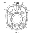
- Figure 3 is an enlarged perspective view of the base of the toilet assembly of Figure 1.
- Figure 4 is a top view of the base of Figure 3.
- Figure 5 is a cross-sectional view taken along the line 5-5 of Figure 4.
- Figure 6 is a bottom view of the bowl assembly.
- Figures 7A, 7B and 7C represent a series of side views of the toilet assembly of Figure 1, shown with a flush lever in a first position (Figure 7A), a second position ( Figure 7B) and a third position (Figure 7C).
- Figures 8A, 8B and 8C represent a corresponding series of side views of the water valve and water valve mounting member, as the water valve is rotated through first, second and third positions corresponding with the first, second and third positions of the flush lever.
- Figures 9A, 9B and 9C represent a series of cross-sectional views of a portion of the toilet assembly of Figure 1, shown with the flush lever and the water valve in their respective first positions (Figure 9A), second positions ( Figure 9B) and third positions (Figure 9C).
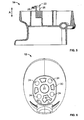
- Figure 10 is a side view of the toilet assembly of Figure 1, shown with the flush lever removed for purposes of illustration.
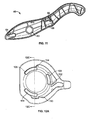
- Figure 11 is a rear view of the flush lever.
- Figure 12A, 12B and 12C are views of a water valve mounting member of the toilet assembly of the present teachings.
- FIG. 13 is a front perspective view of another toilet assembly constructed in accordance with the present teachings.
- flush toilet assembly 10 constructed according to the present teachings is illustrated and generally identified at reference character 10.
- the flush toilet assembly 10 is intended for use within a motor vehicle such as a recreational vehicle or the like.
- the flush toilet assembly 10 of Figures 1-12C is illustrated as a low rise toilet that may be mounted on a platform. As will be discussed below with reference to Figure 13 of the drawings, the flush toilet assembly may be alternatively constructed as a high rise toilet that may be mounted on a platform.
- the toilet assembly 10 is generally shown to include a bowl assembly 12 and a base 14.
- the bowl assembly 12 and the base 14 may be constructed of similar or dissimilar materials.
- the bowl assembly 12 may be constructed of a non-porous material such as vitreous china.
- the base 14 may be constructed of a lighter, less expensive material such as plastic.
- the bowl assembly 12 is shown to include at its lower end a discharge outlet 20 (see, Fig. 6, for example).
- the upper end of the bowl assembly 12 is open to define a bowl 24.
- a lower end of the bowl assembly 12 is mounted to the base 14.
- the bowl assembly 12 may be secured to the base 14 in a manner discussed below.
- the flush toilet 10 is illustrated to generally include a seat 32 and cover 34.
- the seat and cover 32 and 34 may be mounted to the bowl 12 with conventional mounting hardware 36.
- the flush toilet assembly 10 is illustrated to further include a breaker assembly 38 and a nozzle assembly 39.
- One of the bowl assembly 12 and the base 14 may include at least one male coupling element 22.
- the other of the bowl assembly 12 and the base 14 may include at least one cooperating female component 24.
- the at least one male coupling element 22 is carried by the base 14 and the at least one cooperating female component 24 is carried on the bowl assembly.
- the base 14 may include four male coupling elements 22 and the bowl assembly may include four cooperating female coupling elements 24.
- the male coupling elements 22 may be integrally formed with the base 14.
- the male coupling elements 22 may include an upwardly extending portion 26 and a retaining end 28.
- the upwardly extending portion 26 may be curved in a horizontal plane.
- the upwardly extending portion 26 may have a cross section in a horizontal plane that circumscribes at least a portion of a circle.
- the upwardly extending portion 26 may be a portion of a cylindrical tube for purposes of increased strength and the retaining end 28 may extend radially from an upper end of the upwardly extending portion 26.
- the retaining end 28 may be compliant in a vertical direction, as indicated by double arrow A in Figure 5. Such vertical compliance may facilitate secure attachment of the bowl assembly 12 to the base 14.
- the retaining end 28 may downwardly extend from the upper end of the upwardly extending portion 22 and include a lower surface having a convex shape.
- the convex shape of the retaining ends 28 is adapted to engage an inner surface of the bowl assembly 12.
- the female coupling elements may comprise apertures 24 formed in a lower surface 30 of the bowl assembly 12.
- the apertures 24 may be generally circular.
- the apertures 24 are sized and oriented to receive the male coupling elements 22 of the base 14.
- seal member 54 of the flush toilet assembly 10 will be described.
- the seal member 54 provides a single element that performs the function of sealing a vitreous china bowl 24 to a plastic base 14 and also performs the function of sealing at a waste ball valve assembly 44.
- the sealing member 54 also functions to wipe the waste ball valve assembly 44 as the waste ball valve assembly 44 is moved from its closed position to its open position.
- the seal member 54 is retained in the housing 14 by a retaining member 72.
- the seal member 54 may be toroidal in shape and defines a central opening. The central opening may taper in an upward direction to facilitate mating engagement with the central portion of the waste ball valve assembly 44.
- the seal member 54 includes an upwardly extending cylindrical flange and a lower, generally horizontal portion.
- the upwardly extending cylindrical flange may be constructed of compressible foam rubber and the lower, generally horizontal portion may be constructed of generally incompressible solid rubber.
- the upper and lower portions may be laminated to one another.
- the seal member 54 may alternatively be injection or compression molded of a common rubber material.
- the material of the seal member 54 may be a relatively incompressible rubber. Many suitable materials are well known in the art.
- the upper portion of the seal member 54 may include an open cross section to maintain the compressibility of the seal member 54 in a vertical direction.
- a single seal member 54 may perform the dual functions of sealing the vitreous china bowl assembly 12 to a plastic base 14 and sealing/wiping at a ball valve assembly 44.
- the horizontal portion engages the waste ball valve assembly 44 and maintains contact with the central portion of the waste ball valve assembly 44 throughout its rotation. In this manner, the seal member 54 may provide wiping action to remove waste from the waste ball valve assembly 44.
- the lower surface of the lower portion of the seal member 54 may be desirable to treat to reduce the effective coefficient of friction. Such a reduction of the coefficient of friction may further facilitate wiping of the central portion of the waste ball valve assembly 44.
- the lower surface of the lower portion is coated with Teflon.
- the lower surface of the lower portion is chlorinated. Other materials or treatments may be used within the scope of the present teachings to reduce the coefficient of friction.
- the seal retainer 72 provides relative positioning of the seal member 54 to the central portion of the waste ball valve assembly 44.
- the seal retainer 72 also provides a surface against which the seal member 54 may be vertically compressed for sealing the vitreous china bowl assembly 12 to the base 14.
- the seal member 54 can be over-molded of a thermoplastic material directly to the retainer 72. Incorporation of a compliant material allows for variable fit to the bowl assembly 12 to accommodate for vitreous china processing tolerances.
- the base 14 is conventionally mounted to a support surface (e.g., a floor or riser).
- the bowl assembly 12 is placed on top of the base 14 such that the male coupling elements 22 are inserted into the female coupling elements 24.
- the bowl assembly 12 is rotated through approximately 10° - 15° to the orientation shown in Figure 1, for example.
- the compliant retaining ends 28 of the male coupling elements capture the bowl assembly 12.
- fasteners 80 may be inserted through holes 82 in the base.
- the fasteners 80 may engage internally threaded boss partners 84 defined by the base 14.
- the flush toilet assembly 10 may include a flush arrangement controlled by a single actuator 40.
- the actuator is a foot actuated lever 40.
- the foot actuated lever 40 is movable from a first position (as shown in Figure 7A, for example) to a second or intermediate position (as shown in Figure 7B, for example) downwardly pivoted about 25° from the first position.
- the foot actuated lever 40 may be further pivoted from the second position to a third position (as shown in Figure 7C, for example).
- articulation of the lever 40 from the first position to the second position functions to add water to the bowl 24 without opening the discharge opening 20.
- the flush arrangement may generally include a waste valve assembly 44 and a water valve assembly 45.
- the waste valve assembly 44 may be operative to selectively open and close the discharge opening 20 of the bowl assembly 12.
- the water valve assembly 45 may be operative for selectively delivering a source of flush water to the bowl 24 for rinsing and flushing.
- the waste valve assembly may be a waste ball valve assembly 44 include a central portion in the form of a waste ball valve.
- the central portion may be partially spherical in shape and in a manner to become more apparent below cooperate with a seal member 54 for selectively opening and closing the discharge opening 20.
- the waste ball valve assembly 44 is rotatably received in the base 14. As such, the waste ball valve assembly 44 is rotatable between open and closed positions about an axis B (see Figures 9A, 9B and 9C).
- the toilet assembly 10 may define a flush water path 50.
- a portion of the flush water path 50 may be internally defined by the base 14 and may extend between an inlet port 52 and outlet port 53.
- the inlet and outlet ports 52 and 53 may be integrally formed with the base 14.
- the inlet port 52 may be conventionally coupled to a source of flush water (now shown). Positive pressure of the flush water is maintained at the inlet port 52.
- the outlet port 53 may be conventionally coupled to the breaker assembly 38 through a conduit or hose 55 for delivering the source of matter to the nozzle assembly 39.
- the water valve recess 56 may intersect the flush water path 50 and may be generally cylindrical in shape.
- the water valve 46 may be similarly cylindrically shaped and received within the water valve recess 56 for rotation about an axis C.
- the water valve 46 is movable between a first position (shown in Figure 9A), a second position (shown in Figure 9B) and a third position (shown in Figure 9C). These three water valve positions corresponding with the first, second and third positions of the flush lever 40, respectively.
- the water valve 46 is rotatable about the axis C between the first, second and third positions. In the first position, the flush water path 50 is closed. In the second and third positions, the flush water path 50 is open for delivering the source of flush water to the bowl.
- the flush lever 40 may be formed to include a generally cylindrical male extension 60 that is rotatably received within a cylindrical opening 62 defined by the base 14.
- the flush lever 40 may be formed to include a first recess 64 for receiving a driven portion 66 of the water valve 46.
- the driven portion 66 defines a cam member and the recess 64 defines a cam follower.
- the first recess may be an elongated slot 64.
- the flush lever 40 may be additionally formed to define a second recess 68 for receiving a rotatable drive member 70 coupled to the waste valve 44.
- the base 14 may be further formed to include a cylindrical extension 102 for reception and mounting of the water valve 64.
- the cylindrical extension 102 may be formed to include a plurality of radially extending tabs 104 for cooperatively engaging the valve mounting member 47.
- the mounting member 47 defines a circular opening 106 for receiving the water valve 64.
- the mounting member 47 in turn surrounds the cylindrical extension 102. Inwardly extending flanges 108 of the mounting member 47 engage the tabs 104 in a conventional manner to secure the mounting member 47 to the base 14.
- the mounting member 47 may define a plurality of stops for positively locating the flush lever 40 in the first, second and third positions.
- the water valve 46 may rotate relative to the mounting member between first, second and third flush valve positions corresponding to the first, second and third flush level positions 40.
- a radially extending extension 109 that carries that driven portion 66 of the flush valve 64 abuts a first stop 110.
- the first stop 110 prevents further rotation of the water valve 46 in a clockwise direction (as shown in Figure 8A).
- the extension 109 In the second water valve position, the extension 109 abuts a second stop 112 of the mounting member 47.
- the second stop 112 may be shaped like an arm and may inwardly extend toward the extension 109.
- the second stop 112 provides the user with a tactile response to indicate rotation of the flush lever 40 to the second position.
- the extension 109 may apply a column load on the stop 112.
- These cooperating components 109 and 112 may provide for a lighter bending load upon return of the pedal 40. To achieve this lighter bending load upon return, the stop 112 may angle as it extends toward the extension 109.
- the tactile response may be provided through the interconnection of the flush lever 40 and the waste valve 44.
- the extension 109 abuts a third stop 114.
- the third stop prevents further rotation of the water valve 46 in the counterclockwise position (as shown in Figure 8C).
- the flush lever 40 is rotated from the first position to the intermediate position to add water to the bowl 24 without opening the waste valve 44.
- the water valve 46 rotates from its first position to its second position and a window 86 of the water valve 46 is aligned with the flush water path 50 to open the flush water path 50 for the delivery of flush water to the bowl 24.
- a driven portion 88 (see Figure 10) of the drive member 70 may be coupled to the flush lever 40 through a lost motion connection.
- the interconnection of the drive member 70 and the flush lever 40 may provide the user with a tactile response indicating that the flush lever 40 has reached the second or intermediate position and the water valve 46 is open without opening the waste valve 44.
- the driven portion 88 may engage a detent portion 89 of the recess 68.
- no rotation of the waste valve 44 has occurred but the water valve 46 has been opened.
- Engagement of the driven portion 88 with the detent portion 89 provides a tactile response to the user. An increased amount of force is required to advance the flush lever 40 beyond this positively located position established by the driven portion 88 and the detent portion 89.
- the flush lever 40 may engage a second spring to provide additional resistance when the flush lever 40 is advanced beyond the intermediate position.
- FIG. 1 an alternative flush toilet assembly of the present teachings is illustrated and generally identified at reference character 100.
- Various components are common between the flush toilet assemblies. For this reason, like reference numbers are used with reference to Figure 15 to denote like components previously discussed.
- the alternative flush toilet assembly 100 of Figure 15 again differs from the toilet assembly 10 by including a high base adapted to be mounted directly to a floor (e.g., without a riser or platform).
Landscapes
- Engineering & Computer Science (AREA)
- Public Health (AREA)
- Health & Medical Sciences (AREA)
- Mechanical Engineering (AREA)
- Life Sciences & Earth Sciences (AREA)
- Hydrology & Water Resources (AREA)
- Water Supply & Treatment (AREA)
- Aviation & Aerospace Engineering (AREA)
- Epidemiology (AREA)
- General Health & Medical Sciences (AREA)
- Combustion & Propulsion (AREA)
- Ocean & Marine Engineering (AREA)
- Chemical & Material Sciences (AREA)
- Sanitary Device For Flush Toilet (AREA)
Abstract
A flush toilet assembly includes a bowl assembly defining a bowl and a base supporting the bowl assembly. One of the bowl assembly and the base may include at least one male coupling element and the other of the bowl assembly and the base may include at least one cooperating female coupling element. A flush lever may be interconnected to the base for movement between a first position and a second position. The flush lever may include a cam surface. A water valve may be carried to the base and include a cam follower associated with the cam surface of the flush lever. The water valve may be moveable from a water valve closed position to a water valve open position through cooperative engagement of the cam surface and cam follower in response to movement of the flush lever from the first position to the second position. The base may integrally define a flush water path extending between an inlet port and an outlet port. The water valve may be disposed within a water valve recess defined by the base which intersects the flush water path.
Description
- This application claims priority to
United States Provisional Patent Application No. 60/774,891 filed February 17, 2006 United States Provisional Patent Application No. 60/826,952 filed September 22, 2006 - Vehicles, including recreational vehicles ("RVs"), airplanes, boats, trains and the like, often include toilets for the comfort and convenience of the passengers. The toilets of vehicles must be designed for use environments that are significantly different from non-transitory toilets conventionally found in homes and businesses ("home toilets"). Vehicle toilets should also provide the user with features common to home toilets.
- One example of a vehicle toilet is shown and described in commonly assigned
United States Patent No. 6,397,405 which is hereby incorporated by reference as if fully set forth herein.United States Patent No. 6,397,405 discloses various embodiments having a bowl portion and a base portion unitarily constructed of a common material. The integrally formed base portion varies in height depending on the particularly intended use environment. In this regard, in certain embodiments the base is configured for a high-rise application in which the toilet is to be directly supported on a floor. In other embodiments, the base is configured for a low-rise application in which the toilet is to be supported on a platform elevated from the floor. - While known toilets, including the toilet disclosed by
United States Patent No. 6,397,405 , have proven acceptable for their intended applications, there remains a need for continuous improvement in the pertinent art. - According to one aspect, the present teachings provide a flush toilet assembly for a motor vehicle comprising a bowl assembly defining a bowl and a discharge opening at a lower end of the bowl and a base coupled to the bowl assembly. One of the bowl assembly and the base includes at least one male coupling element. The other of the bowl and the base includes at least one cooperating female coupling element.
- According to another aspect, the present teachings provide a housing integrally defining a flush water path. The flush water path extends between an inlet port and an outlet port. The housing further defines a water valve recess. The water valve recess intersects the flush water path. A water valve is mounted in the water valve recess for movement between a first water valve position and a second water valve position. In the first water valve position, the flush water path is closed. In the second water valve position, the flush water path is open.
- According to yet another aspect, the present teachings provide a flush toilet including a base, an actuator and a water valve and a flush lever. The flush lever is interconnected to the base for movement between a first position and a second position and includes a cam surface. The water valve is carried by the base. The water valve includes a cam follower associated with the cam surface and is moveable from a water valve closing position to a water valve open position through cooperative engagement of the dam surface and cam follower in response to movement of the flush lever from the first position to the second position.
- According to yet another aspect, the present teachings provide a flush toilet comprising a main body including a bowl. The flush toilet further includes a water valve and a waste valve. The water valve is in fluid communication with the bowl and is operative for delivering a source of flush water to the bowl. The waste valve associated with a bowl opening. A flush lever is coupled to the main body and is operatively interconnected to the waste valve and the flush valve. The flush lever is moveable between a first position, a second position and a third position such that in the first position the waste valve is closed and the water valve is closed, in the second position the waste valve is closed and the water valve is open and in the third position the waste valve is open and the water valve is open.
- Further areas of applicability of the present teachings will become apparent from the detailed description provided hereinafter. It should be understood that the detailed description and specific examples, while indicating exemplary embodiments of the invention, are intended for purposes of illustration only and are not intended to limit the scope of the invention.
- The present teachings will become more fully understood from the detailed description and the accompanying drawings, wherein:
- Figure 1 is a front perspective view of a toilet assembly constructed in accordance with the present teachings.
- Figure 2 is an exploded perspective of the toilet assembly of Figure 1.
- Figure 3 is an enlarged perspective view of the base of the toilet assembly of Figure 1.
- Figure 4 is a top view of the base of Figure 3.
- Figure 5 is a cross-sectional view taken along the line 5-5 of Figure 4.
- Figure 6 is a bottom view of the bowl assembly.
- Figures 7A, 7B and 7C represent a series of side views of the toilet assembly of Figure 1, shown with a flush lever in a first position (Figure 7A), a second position (Figure 7B) and a third position (Figure 7C).
- Figures 8A, 8B and 8C represent a corresponding series of side views of the water valve and water valve mounting member, as the water valve is rotated through first, second and third positions corresponding with the first, second and third positions of the flush lever. Figures 9A, 9B and 9C represent a series of cross-sectional views of a portion of the toilet assembly of Figure 1, shown with the flush lever and the water valve in their respective first positions (Figure 9A), second positions (Figure 9B) and third positions (Figure 9C).
- Figure 10 is a side view of the toilet assembly of Figure 1, shown with the flush lever removed for purposes of illustration.
- Figure 11 is a rear view of the flush lever.
- Figure 12A, 12B and 12C are views of a water valve mounting member of the toilet assembly of the present teachings.
- Figure 13 is a front perspective view of another toilet assembly constructed in accordance with the present teachings.
- The following description of various aspects of the present teachings is merely exemplary in nature and is in no way intended to limit the invention, its application or uses.
- With general reference to the drawings, a flush toilet assembly constructed according to the present teachings is illustrated and generally identified at
reference character 10. In one particular application, theflush toilet assembly 10 is intended for use within a motor vehicle such as a recreational vehicle or the like. After a reading of the remainder of this detailed description, however, those skilled in the art will readily appreciate that the present teachings are not limited to such use. Rather, various of the teachings of the present teachings have applicability to other vehicle and non-vehicle applications. - The
flush toilet assembly 10 of Figures 1-12C is illustrated as a low rise toilet that may be mounted on a platform. As will be discussed below with reference to Figure 13 of the drawings, the flush toilet assembly may be alternatively constructed as a high rise toilet that may be mounted on a platform. Thetoilet assembly 10 is generally shown to include abowl assembly 12 and abase 14. Thebowl assembly 12 and thebase 14 may be constructed of similar or dissimilar materials. Thebowl assembly 12 may be constructed of a non-porous material such as vitreous china. Thebase 14 may be constructed of a lighter, less expensive material such as plastic. - The
bowl assembly 12 is shown to include at its lower end a discharge outlet 20 (see, Fig. 6, for example). The upper end of thebowl assembly 12 is open to define abowl 24. A lower end of thebowl assembly 12 is mounted to thebase 14. Thebowl assembly 12 may be secured to the base 14 in a manner discussed below. - With particular reference to the exploded view of Figure 2, the
flush toilet 10 is illustrated to generally include aseat 32 andcover 34. The seat and cover 32 and 34 may be mounted to thebowl 12 with conventional mountinghardware 36. Theflush toilet assembly 10 is illustrated to further include abreaker assembly 38 and anozzle assembly 39. These features are further described in commonly owned U. S. Serial No.10/540,006 - One of the
bowl assembly 12 and the base 14 may include at least onemale coupling element 22. The other of thebowl assembly 12 and the base 14 may include at least one cooperatingfemale component 24. In one particular application, the at least onemale coupling element 22 is carried by thebase 14 and the at least one cooperatingfemale component 24 is carried on the bowl assembly. In this particular application, thebase 14 may include fourmale coupling elements 22 and the bowl assembly may include four cooperatingfemale coupling elements 24. Those skilled in the art, however, will appreciate that a greater or lesser number of male andfemale coupling elements - With particular reference to Figure 3-5, the
male coupling elements 22 may be integrally formed with thebase 14. Themale coupling elements 22 may include an upwardly extendingportion 26 and a retainingend 28. The upwardly extendingportion 26 may be curved in a horizontal plane. In this regard, the upwardly extendingportion 26 may have a cross section in a horizontal plane that circumscribes at least a portion of a circle. The upwardly extendingportion 26 may be a portion of a cylindrical tube for purposes of increased strength and the retainingend 28 may extend radially from an upper end of the upwardly extendingportion 26. The retainingend 28 may be compliant in a vertical direction, as indicated by double arrow A in Figure 5. Such vertical compliance may facilitate secure attachment of thebowl assembly 12 to thebase 14. The retainingend 28 may downwardly extend from the upper end of the upwardly extendingportion 22 and include a lower surface having a convex shape. The convex shape of the retaining ends 28 is adapted to engage an inner surface of thebowl assembly 12. - As perhaps most particularly shown in Figure 6, the female coupling elements may comprise
apertures 24 formed in alower surface 30 of thebowl assembly 12. Theapertures 24 may be generally circular. Theapertures 24 are sized and oriented to receive themale coupling elements 22 of thebase 14. - With particular reference to the exploded view of Figure 2, a
seal member 54 of theflush toilet assembly 10 will be described. As will become understood by those skilled in the art, theseal member 54 provides a single element that performs the function of sealing avitreous china bowl 24 to aplastic base 14 and also performs the function of sealing at a wasteball valve assembly 44. The sealingmember 54 also functions to wipe the wasteball valve assembly 44 as the wasteball valve assembly 44 is moved from its closed position to its open position. - The
seal member 54 is retained in thehousing 14 by a retainingmember 72. Theseal member 54 may be toroidal in shape and defines a central opening. The central opening may taper in an upward direction to facilitate mating engagement with the central portion of the wasteball valve assembly 44. Theseal member 54 includes an upwardly extending cylindrical flange and a lower, generally horizontal portion. In one particular embodiment, the upwardly extending cylindrical flange may be constructed of compressible foam rubber and the lower, generally horizontal portion may be constructed of generally incompressible solid rubber. The upper and lower portions may be laminated to one another. - The
seal member 54 may alternatively be injection or compression molded of a common rubber material. The material of theseal member 54 may be a relatively incompressible rubber. Many suitable materials are well known in the art. The upper portion of theseal member 54 may include an open cross section to maintain the compressibility of theseal member 54 in a vertical direction. - The upwardly extending cylindrical flange is compressed between the
bowl assembly 12 and thebase 14 and provides a water-tight seal between thebowl assembly 12 and thebase 14. Thus, asingle seal member 54 may perform the dual functions of sealing the vitreouschina bowl assembly 12 to aplastic base 14 and sealing/wiping at aball valve assembly 44. The horizontal portion engages the wasteball valve assembly 44 and maintains contact with the central portion of the wasteball valve assembly 44 throughout its rotation. In this manner, theseal member 54 may provide wiping action to remove waste from the wasteball valve assembly 44. - In certain applications it may be desirable to treat the lower surface of the lower portion of the
seal member 54 to reduce the effective coefficient of friction. Such a reduction of the coefficient of friction may further facilitate wiping of the central portion of the wasteball valve assembly 44. In one application, the lower surface of the lower portion is coated with Teflon. In another application, the lower surface of the lower portion is chlorinated. Other materials or treatments may be used within the scope of the present teachings to reduce the coefficient of friction. - The
seal retainer 72 provides relative positioning of theseal member 54 to the central portion of the wasteball valve assembly 44. Theseal retainer 72 also provides a surface against which theseal member 54 may be vertically compressed for sealing the vitreouschina bowl assembly 12 to thebase 14. In certain applications, theseal member 54 can be over-molded of a thermoplastic material directly to theretainer 72. Incorporation of a compliant material allows for variable fit to thebowl assembly 12 to accommodate for vitreous china processing tolerances. - During assembly, the
base 14 is conventionally mounted to a support surface (e.g., a floor or riser). Thebowl assembly 12 is placed on top of the base 14 such that themale coupling elements 22 are inserted into thefemale coupling elements 24. Thebowl assembly 12 is rotated through approximately 10° - 15° to the orientation shown in Figure 1, for example. The compliant retaining ends 28 of the male coupling elements capture thebowl assembly 12. Additionally,fasteners 80 may be inserted throughholes 82 in the base. Thefasteners 80 may engage internally threadedboss partners 84 defined by thebase 14. - The
flush toilet assembly 10 may include a flush arrangement controlled by asingle actuator 40. In the embodiment illustrated, the actuator is a foot actuatedlever 40. The foot actuatedlever 40 is movable from a first position (as shown in Figure 7A, for example) to a second or intermediate position (as shown in Figure 7B, for example) downwardly pivoted about 25° from the first position. The foot actuatedlever 40 may be further pivoted from the second position to a third position (as shown in Figure 7C, for example). As will be more further discussed below, articulation of thelever 40 from the first position to the second position functions to add water to thebowl 24 without opening thedischarge opening 20. Continued articulation of thelever 40 from the second position to the third position functions to selectively open the discharge opening 20 of thebowl assembly 12 and functions to selectively deliver a source of flush water to thebowl 24 of thebowl assembly 12 for flushing. It will be appreciated by those skilled in that art that various aspects of the present teachings may alternatively be employed with a hand actuated lever or an electronically controlled arrangement. - The flush arrangement may generally include a
waste valve assembly 44 and a water valve assembly 45. In a manner to be discussed, thewaste valve assembly 44 may be operative to selectively open and close the discharge opening 20 of thebowl assembly 12. The water valve assembly 45 may be operative for selectively delivering a source of flush water to thebowl 24 for rinsing and flushing. - The waste valve assembly may be a waste
ball valve assembly 44 include a central portion in the form of a waste ball valve. The central portion may be partially spherical in shape and in a manner to become more apparent below cooperate with aseal member 54 for selectively opening and closing thedischarge opening 20. The wasteball valve assembly 44 is rotatably received in thebase 14. As such, the wasteball valve assembly 44 is rotatable between open and closed positions about an axis B (see Figures 9A, 9B and 9C). - The
toilet assembly 10 may define aflush water path 50. A portion of theflush water path 50 may be internally defined by thebase 14 and may extend between aninlet port 52 andoutlet port 53. The inlet andoutlet ports base 14. Theinlet port 52 may be conventionally coupled to a source of flush water (now shown). Positive pressure of the flush water is maintained at theinlet port 52. Theoutlet port 53 may be conventionally coupled to thebreaker assembly 38 through a conduit orhose 55 for delivering the source of matter to thenozzle assembly 39. - The water valve recess 56 (see Figures 9A-9C, for example) may intersect the
flush water path 50 and may be generally cylindrical in shape. Thewater valve 46 may be similarly cylindrically shaped and received within thewater valve recess 56 for rotation about an axis C. - The
water valve 46 is movable between a first position (shown in Figure 9A), a second position (shown in Figure 9B) and a third position (shown in Figure 9C). These three water valve positions corresponding with the first, second and third positions of theflush lever 40, respectively. In the embodiment illustrated, thewater valve 46 is rotatable about the axis C between the first, second and third positions. In the first position, theflush water path 50 is closed. In the second and third positions, theflush water path 50 is open for delivering the source of flush water to the bowl. - The
flush lever 40 may be formed to include a generally cylindricalmale extension 60 that is rotatably received within acylindrical opening 62 defined by thebase 14. Theflush lever 40 may be formed to include afirst recess 64 for receiving a drivenportion 66 of thewater valve 46. The drivenportion 66 defines a cam member and therecess 64 defines a cam follower. The first recess may be anelongated slot 64. Theflush lever 40 may be additionally formed to define asecond recess 68 for receiving arotatable drive member 70 coupled to thewaste valve 44. - The base 14 may be further formed to include a
cylindrical extension 102 for reception and mounting of thewater valve 64. Thecylindrical extension 102 may be formed to include a plurality of radially extendingtabs 104 for cooperatively engaging thevalve mounting member 47. In this regard, the mountingmember 47 defines a circular opening 106 for receiving thewater valve 64. The mountingmember 47 in turn surrounds thecylindrical extension 102. Inwardly extendingflanges 108 of the mountingmember 47 engage thetabs 104 in a conventional manner to secure the mountingmember 47 to thebase 14. - The mounting
member 47 may define a plurality of stops for positively locating theflush lever 40 in the first, second and third positions. Thewater valve 46 may rotate relative to the mounting member between first, second and third flush valve positions corresponding to the first, second and third flush level positions 40. In the first flush valve position, aradially extending extension 109 that carries that drivenportion 66 of theflush valve 64 abuts afirst stop 110. Thefirst stop 110 prevents further rotation of thewater valve 46 in a clockwise direction (as shown in Figure 8A). - In the second water valve position, the
extension 109 abuts asecond stop 112 of the mountingmember 47. Thesecond stop 112 may be shaped like an arm and may inwardly extend toward theextension 109. Thesecond stop 112 provides the user with a tactile response to indicate rotation of theflush lever 40 to the second position. In this regard, theextension 109 may apply a column load on thestop 112. These cooperatingcomponents pedal 40. To achieve this lighter bending load upon return, thestop 112 may angle as it extends toward theextension 109. In other applications, and as discussed below, the tactile response may be provided through the interconnection of theflush lever 40 and thewaste valve 44. - In the third water valve position, the
extension 109 abuts athird stop 114. The third stop prevents further rotation of thewater valve 46 in the counterclockwise position (as shown in Figure 8C). - In operation, the
flush lever 40 is rotated from the first position to the intermediate position to add water to thebowl 24 without opening thewaste valve 44. During this rotation of theflush lever 40, thewater valve 46 rotates from its first position to its second position and awindow 86 of thewater valve 46 is aligned with theflush water path 50 to open theflush water path 50 for the delivery of flush water to thebowl 24. - A driven portion 88 (see Figure 10) of the
drive member 70 may be coupled to theflush lever 40 through a lost motion connection. In certain applications, the interconnection of thedrive member 70 and theflush lever 40 may provide the user with a tactile response indicating that theflush lever 40 has reached the second or intermediate position and thewater valve 46 is open without opening thewaste valve 44. In this regard, when theflush lever 40 is rotated to the intermediate position, the drivenportion 88 may engage adetent portion 89 of therecess 68. At this point, no rotation of thewaste valve 44 has occurred but thewater valve 46 has been opened. Engagement of the drivenportion 88 with thedetent portion 89 provides a tactile response to the user. An increased amount of force is required to advance theflush lever 40 beyond this positively located position established by the drivenportion 88 and thedetent portion 89. Alternatively, theflush lever 40 may engage a second spring to provide additional resistance when theflush lever 40 is advanced beyond the intermediate position. - Further rotation of the
lever 40 from the intermediate position to the second position results in rotation of the wasteball valve assembly 44 from its closed position to its open position. During such rotation, thewater valve 46 remains open for the delivery of flush water to thebowl 24. When the user discontinues the application of force to theflush lever 40, theflush lever 40 returns to its first position by aspring 90. - Turning now to the perspective view of Figure 12, an alternative flush toilet assembly of the present teachings is illustrated and generally identified at
reference character 100. Various components are common between the flush toilet assemblies. For this reason, like reference numbers are used with reference to Figure 15 to denote like components previously discussed. The alternativeflush toilet assembly 100 of Figure 15 again differs from thetoilet assembly 10 by including a high base adapted to be mounted directly to a floor (e.g., without a riser or platform). - The description of the present teachings is merely exemplary in nature and, thus, variations that do not depart from the gist of the invention are intended to be within the scope of the invention. Such variations are not to be regarded as a departure from the spirit and scope of the invention. Furthermore, the present invention has been described with reference to two particular embodiments having many common and some distinct features. One skilled in the art will recognize that these features may be used singularly or in any combination based on the requirements and specifications of a given application or design.
Claims (24)
- A flush toilet assembly comprising:a bowl assembly defining a bowl; anda base supporting the bowl assembly;wherein one of the bowl assembly and the base includes at least one male coupling element and the other of the bowl assembly and the base includes at least one cooperating female coupling element.
- The flush toilet assembly of Claim 1, wherein the one of the bowl assembly and the base includes a plurality of the male coupling elements.
- The flush toilet assembly of Claim 1, wherein the base includes the at least one male coupling element.
- The flush toilet assembly of Claim 1, wherein the at least one male coupling element is compliant.
- The flush toilet assembly of Claim 1, wherein the bowl assembly rotates relative the base to engage the at least one male coupling element with the at least one female coupling element.
- The flush toilet assembly of Claim 1, wherein the bowl assembly and the base are constructed of distinct materials.
- The flush toilet assembly of Claim 1, wherein at least one of the bowl assembly and the base is constructed of a non-porous material.
- The flush toilet assembly of Claim 1, wherein the at least one male coupling is unitarily constructed with the remainder of the one of the bowl assembly and the base.
- The flush toilet assembly of Claim 1, wherein the at least one male coupling element includes an upwardly extending portion and a retaining end, the upwardly extending portion having a cross section in a horizontal plane that circumscribes at least a portion of a circle.
- The flush toilet assembly of Claim 8, wherein the at least one male coupling element includes an upwardly extending portion and a retaining end, the upwardly extending portion being curved in a horizontal plane.
- A flush toilet comprising:a base;a flush lever interconnected to the base for movement between a first position and a second position, the flush lever Including a cam surface; anda water valve carried to the base, the water valve including a cam follower associated with the cam surface, the water valve moveable from a water valve closing position to a water valve open position through cooperative engagement of the cam surface and cam follower in response to movement of the flush lever from the first position to the second position.
- The flush toilet comprising of claim 11, further comprising a flush valve, the flush valve moveable from a flush valve closed position to a flush valve open position in response the movement to movement of the flush lever from the first position to the second position.
- The flush toilet comprising of claim 12, wherein the flush valve is a ball valve interconnected to the base, the ball valve and the flush lever are rotatable about a common axis.
- The flush toilet comprising of claim 12, wherein the water valve is rotatable about a water valve axis, the water valve axis being parallel to and spaced apart from the common axis.
- The flush toilet comprising of claim 11, wherein the water valve is generally cylindrical and rotatable about a water valve closed position and the water valve open position.
- The flush toilet comprising of claim 11, wherein the flush lever is moveable to an intermediate position, the water valve being in the water valve open position and the waste valve being in the waste closed position when the actuator is in the intermediate position.
- The flush toilet comprising of claim 16, further comprising a detent carried by the toilet, the detent providing a tactile response to a user upon movement to the second position.
- A flush toilet assembly comprising:a housing integrally defining a flush water path extending between an inlet port and an outlet port, the housing further defining a water valve recess, the water valve recess intersecting the flush water path; anda water valve mounted in the water valve recess, the water valve movable between a first water valve position and a second water valve position such that flush water path is closed in the first position and open in the second position.
- The flush toilet assembly of claim 18, wherein the water valve is rotatable between the first water valve position and the second water valve position.
- The flush toilet assembly of claim 19, further comprising a flush lever mounted to the housing for movement between a first flush lever position and a second flush lever position for controlling rotation of the water valve from the first water valve position to the second water valve position.
- The flush toilet assembly of claim 18, wherein the water valve may be controlled distinctly in a water add mode and a flush mode.
- A flush toilet comprising:a main body including a bowl;a water valve in fluid communication with the bowl and operative for delivering a source of flush water to the bowl;a waste valve associated with a bowl opening; anda flush lever coupled to the main body and operatively interconnected to the waste valve and the flush valve, the flush lever moveable between a first position, a second position and a third position such that in the first position the waste valve is closed and the water valve is closed, in the second position the waste valve is closed and the water valve is open and in the third position the waste valve is open and the water valve is open.
- The flush toilet assembly of claim 22, wherein the flush lever is rotatable coupled to the housing and operates to rotate the waste valve about a first axis and the water valve about a second axis.
- The flush toilet assembly of claim 22, wherein an interconnection between the flush lever and at least one of the waste valve and water valve provides a user with a tactile response after the flush lever is rotated to the second position and before the flush lever is rotated to the third position.
Applications Claiming Priority (3)
| Application Number | Priority Date | Filing Date | Title |
|---|---|---|---|
| US77489106P | 2006-02-17 | 2006-02-17 | |
| US82695206P | 2006-09-26 | 2006-09-26 | |
| US11/674,847 US7765625B2 (en) | 2006-02-17 | 2007-02-14 | Flush toilet assembly |
Publications (1)
| Publication Number | Publication Date |
|---|---|
| EP1820913A2 true EP1820913A2 (en) | 2007-08-22 |
Family
ID=38426588
Family Applications (1)
| Application Number | Title | Priority Date | Filing Date |
|---|---|---|---|
| EP07003287A Withdrawn EP1820913A2 (en) | 2006-02-17 | 2007-02-16 | Flush toilet assembly |
Country Status (2)
| Country | Link |
|---|---|
| US (1) | US7765625B2 (en) |
| EP (1) | EP1820913A2 (en) |
Cited By (4)
| Publication number | Priority date | Publication date | Assignee | Title |
|---|---|---|---|---|
| WO2012000156A1 (en) * | 2010-07-02 | 2012-01-05 | Tang Bingsheng | Direct discharge sealing system of water closet |
| WO2013024017A1 (en) * | 2011-08-17 | 2013-02-21 | Dometic Gmbh | Toilet for vehicles, in particular for buses, motorhomes, caravans and yachts |
| CN105297864A (en) * | 2015-10-14 | 2016-02-03 | 安徽上诺环保股份有限公司 | Novel portable environmental-friendly pedestal pan |
| CN106193238A (en) * | 2016-08-30 | 2016-12-07 | 中山市艾呦呦智能家居科技有限公司 | An environmentally friendly toilet |
Families Citing this family (8)
| Publication number | Priority date | Publication date | Assignee | Title |
|---|---|---|---|---|
| CN102171401B (en) * | 2008-10-03 | 2015-06-24 | B/E航空公司 | Vacuum waste system and method for using the same |
| CA2787306C (en) * | 2010-02-16 | 2017-10-24 | Almos Technologies Pty. Ltd. | Pump assembly for a marine toilet and toilet pump connection system |
| USD654575S1 (en) | 2010-09-22 | 2012-02-21 | Thetford Corporation | Wall mounted toilet |
| USD654576S1 (en) | 2010-09-22 | 2012-02-21 | Thetford Corporation | Wall mounted bidet |
| DE102012208243A1 (en) * | 2012-05-16 | 2013-11-21 | Siemens Aktiengesellschaft | Shut-off valve with heating element, in particular for a rail vehicle |
| US9879437B2 (en) * | 2013-02-05 | 2018-01-30 | Bertram Y. ITO | Transportable restroom |
| US9957701B2 (en) | 2013-02-05 | 2018-05-01 | Bertram Y. ITO | Roof assembly for a transportable restroom |
| US9340963B2 (en) | 2013-02-05 | 2016-05-17 | Bertram Y. ITO | Transportable restroom |
Family Cites Families (39)
| Publication number | Priority date | Publication date | Assignee | Title |
|---|---|---|---|---|
| US2068406A (en) * | 1935-10-21 | 1937-01-19 | Edith F Freed | Fluid flow control apparatus |
| US3308481A (en) * | 1964-09-01 | 1967-03-14 | Robert F O'brien | Toilet construction |
| US3599248A (en) * | 1968-12-11 | 1971-08-17 | Mansfield Sanitary Inc | Trapless toilet bowl fixture and ring diaphragm therefor |
| US3860973A (en) * | 1973-04-04 | 1975-01-21 | Itt | Toilet construction |
| GB1482201A (en) | 1973-11-22 | 1977-08-10 | Thetford Aqua Prod Ltd | Toilet |
| US3949430A (en) | 1975-01-20 | 1976-04-13 | Thetford Corporation | Portable toilet |
| US4032996A (en) | 1976-08-04 | 1977-07-05 | Thetford Corporation | Sealing apparatus for toilet |
| GB1570955A (en) | 1977-07-25 | 1980-07-09 | Thetford Aqua Prod Ltd | Toilet |
| US4145773A (en) | 1978-04-03 | 1979-03-27 | Thetford Corporation | Portable toilet with vent means for the holding tank |
| US4185337A (en) | 1978-09-26 | 1980-01-29 | Thetford Corporation | Portable toilet with improved flush apparatus |
| US4180876A (en) | 1978-11-06 | 1980-01-01 | Thetford Corporation | Portable toilets |
| US4185340A (en) | 1978-11-22 | 1980-01-29 | Thetford Corporation | Toilet apparatus |
| US4215445A (en) | 1979-09-14 | 1980-08-05 | Thetford Corporation | Portable toilets |
| US4217668A (en) | 1979-09-20 | 1980-08-19 | Thetford Corporation | Portable toilet |
| US4589148A (en) | 1984-12-04 | 1986-05-20 | Thetford Corporation | Toilet hinge |
| US4710988A (en) * | 1986-02-19 | 1987-12-08 | Sanitation Equipment Limited | Flush toilet |
| US5056166A (en) | 1986-06-05 | 1991-10-15 | Thetford Corporation | Self-contained RV sanitary systems |
| US4776631A (en) | 1986-06-05 | 1988-10-11 | Thetford Corporation | Self-contained RV sanitary systems |
| US4974899A (en) | 1986-06-05 | 1990-12-04 | Thetford Corporation | Recreational vehicle use system particularly tank installation |
| US4944048A (en) | 1986-06-05 | 1990-07-31 | Thetford Corporation | Self-contained RV sanitary system |
| US5010602A (en) | 1987-10-27 | 1991-04-30 | Thetford Corporation | Toilet with pulsed flow of flush water |
| US4926508A (en) | 1987-10-27 | 1990-05-22 | Thetford Corporation | Portable toilet with battery operated flush assembly |
| US4850064A (en) | 1987-11-09 | 1989-07-25 | Thetford Corporation | Portable toilet with vent for flush water supply tank |
| US4982456A (en) | 1987-11-09 | 1991-01-08 | Thetford Corporation | Portable toilet with vent for flush water supply tank |
| US4805660A (en) | 1987-11-09 | 1989-02-21 | Thetford Corporation | Vent structure for flush water holding tank of vehicle toilets |
| US4888832A (en) | 1988-06-17 | 1989-12-26 | Thetford Corporation | Toilet with manual flush |
| US5031249A (en) | 1989-06-23 | 1991-07-16 | Thetford Corporation | Universal recreational vehicle toilet system with removable holding tank |
| US5060320A (en) | 1990-06-25 | 1991-10-29 | Thetford Corporation | Recreational vehicle toilet with foot pedal flush |
| US5073994A (en) | 1990-09-12 | 1991-12-24 | Thetford Corporation | Low water toilet with pulsed flush |
| WO1996006234A1 (en) | 1994-08-23 | 1996-02-29 | Thetford Corporation | A sanitary toilet with integral water supply and manual flush assembly |
| US5557810A (en) | 1994-08-24 | 1996-09-24 | Thetford Corporation | Portable toilet with battery operated flush assembly |
| US5715544A (en) | 1995-11-22 | 1998-02-10 | Thetford Corporation | Toilet with improved flush nozzle |
| US5875499A (en) | 1998-01-23 | 1999-03-02 | Thetford Corporation | Recreational vehicle toilet with flush nozzle deflector shield |
| US5906011A (en) * | 1998-09-30 | 1999-05-25 | Sanitation Equipment Limited | Dual foot pedal-operated flush toilet |
| US6397405B1 (en) | 2000-04-11 | 2002-06-04 | Thetford Corporation | Flush toilet for RV's and boats |
| DE10203521A1 (en) * | 2002-01-30 | 2003-07-31 | Modine Mfg Co | Quick Couplings |
| AU2003295995A1 (en) | 2002-11-30 | 2004-06-23 | Thetford Corporation | Reduced water consumption flush toilet |
| US7293298B2 (en) | 2003-04-04 | 2007-11-13 | Thetford Corporation | Self-contained sanitary system for a vehicle |
| US20070240772A1 (en) | 2006-04-13 | 2007-10-18 | Thetford Corporation | In-line, one-way valve assembly |
-
2007
- 2007-02-14 US US11/674,847 patent/US7765625B2/en active Active
- 2007-02-16 EP EP07003287A patent/EP1820913A2/en not_active Withdrawn
Cited By (5)
| Publication number | Priority date | Publication date | Assignee | Title |
|---|---|---|---|---|
| WO2012000156A1 (en) * | 2010-07-02 | 2012-01-05 | Tang Bingsheng | Direct discharge sealing system of water closet |
| WO2013024017A1 (en) * | 2011-08-17 | 2013-02-21 | Dometic Gmbh | Toilet for vehicles, in particular for buses, motorhomes, caravans and yachts |
| CN105297864A (en) * | 2015-10-14 | 2016-02-03 | 安徽上诺环保股份有限公司 | Novel portable environmental-friendly pedestal pan |
| CN106193238A (en) * | 2016-08-30 | 2016-12-07 | 中山市艾呦呦智能家居科技有限公司 | An environmentally friendly toilet |
| CN106193238B (en) * | 2016-08-30 | 2019-05-24 | 中山市艾呦呦智能家居科技有限公司 | Environment-friendly closestool |
Also Published As
| Publication number | Publication date |
|---|---|
| US7765625B2 (en) | 2010-08-03 |
| US20070192951A1 (en) | 2007-08-23 |
Similar Documents
| Publication | Publication Date | Title |
|---|---|---|
| US7765625B2 (en) | Flush toilet assembly | |
| US9080323B2 (en) | Sealing member for a flush toilet | |
| US8480177B2 (en) | Armrest device | |
| US12263717B2 (en) | Air outlet, heater or air conditioning unit with such an air outlet, recreational vehicle with an air outlet, heater and/or air conditioning unit and methods for attaching, operating and converting an air outlet | |
| EP1972728A2 (en) | Flush toilet | |
| EP1548344B1 (en) | Opening and closing valve | |
| JPH0921454A (en) | Support device for shift lever for manual transmission | |
| CN108349438A (en) | The ancon equipped with the hinged handrail of warp including improved unlocking mechanism | |
| EP2060684A1 (en) | Toilet with controller controlling water inlet vavle and flush valve | |
| CN100478081C (en) | Dispensing pump | |
| US9816259B2 (en) | Water tank system for toilet | |
| US9352672B2 (en) | Inertial latch system for a vehicle seat | |
| CA3106658C (en) | Gear-driven trip lever with clutch assembly | |
| US20180142779A1 (en) | Actuating device for an electro-mechanical or hydro-mechanical motor vehicle transmission system, especially of an agricultural commercial vehicle | |
| CN212375966U (en) | A wrench device for a drain valve | |
| US11365536B1 (en) | Extender device for toilet flush activator | |
| EP2146013A1 (en) | Trip lever assembly | |
| JP6983711B2 (en) | Pushbutton switch | |
| CN101018495A (en) | Container | |
| EP1698793B1 (en) | Master cylinder | |
| CA2332274A1 (en) | Combination of a non-return valve with a device | |
| JP3560789B2 (en) | Rotating member position holding device and toilet bowl equipped with this device | |
| DE112023005054T5 (en) | WASHABLE FAUCET LEVER WITH CRANK-OPERATED DETERGENT DISPENSING DEVICE | |
| KR102106436B1 (en) | Operation lever | |
| CN110906011A (en) | Electrohydraulic integrated control valve |
Legal Events
| Date | Code | Title | Description |
|---|---|---|---|
| PUAI | Public reference made under article 153(3) epc to a published international application that has entered the european phase |
Free format text: ORIGINAL CODE: 0009012 |
|
| AK | Designated contracting states |
Kind code of ref document: A2 Designated state(s): AT BE BG CH CY CZ DE DK EE ES FI FR GB GR HU IE IS IT LI LT LU LV MC NL PL PT RO SE SI SK TR |
|
| AX | Request for extension of the european patent |
Extension state: AL BA HR MK YU |
|
| STAA | Information on the status of an ep patent application or granted ep patent |
Free format text: STATUS: THE APPLICATION IS DEEMED TO BE WITHDRAWN |
|
| 18D | Application deemed to be withdrawn |
Effective date: 20100901 |