EP1820879A1 - Durable reactive thermal barrier coatings - Google Patents
Durable reactive thermal barrier coatings Download PDFInfo
- Publication number
- EP1820879A1 EP1820879A1 EP07250209A EP07250209A EP1820879A1 EP 1820879 A1 EP1820879 A1 EP 1820879A1 EP 07250209 A EP07250209 A EP 07250209A EP 07250209 A EP07250209 A EP 07250209A EP 1820879 A1 EP1820879 A1 EP 1820879A1
- Authority
- EP
- European Patent Office
- Prior art keywords
- oxide
- layer
- group
- substrate
- turbine engine
- Prior art date
- Legal status (The legal status is an assumption and is not a legal conclusion. Google has not performed a legal analysis and makes no representation as to the accuracy of the status listed.)
- Granted
Links
Images
Classifications
-
- C—CHEMISTRY; METALLURGY
- C23—COATING METALLIC MATERIAL; COATING MATERIAL WITH METALLIC MATERIAL; CHEMICAL SURFACE TREATMENT; DIFFUSION TREATMENT OF METALLIC MATERIAL; COATING BY VACUUM EVAPORATION, BY SPUTTERING, BY ION IMPLANTATION OR BY CHEMICAL VAPOUR DEPOSITION, IN GENERAL; INHIBITING CORROSION OF METALLIC MATERIAL OR INCRUSTATION IN GENERAL
- C23C—COATING METALLIC MATERIAL; COATING MATERIAL WITH METALLIC MATERIAL; SURFACE TREATMENT OF METALLIC MATERIAL BY DIFFUSION INTO THE SURFACE, BY CHEMICAL CONVERSION OR SUBSTITUTION; COATING BY VACUUM EVAPORATION, BY SPUTTERING, BY ION IMPLANTATION OR BY CHEMICAL VAPOUR DEPOSITION, IN GENERAL
- C23C14/00—Coating by vacuum evaporation, by sputtering or by ion implantation of the coating forming material
- C23C14/06—Coating by vacuum evaporation, by sputtering or by ion implantation of the coating forming material characterised by the coating material
- C23C14/08—Oxides
- C23C14/083—Oxides of refractory metals or yttrium
-
- C—CHEMISTRY; METALLURGY
- C23—COATING METALLIC MATERIAL; COATING MATERIAL WITH METALLIC MATERIAL; CHEMICAL SURFACE TREATMENT; DIFFUSION TREATMENT OF METALLIC MATERIAL; COATING BY VACUUM EVAPORATION, BY SPUTTERING, BY ION IMPLANTATION OR BY CHEMICAL VAPOUR DEPOSITION, IN GENERAL; INHIBITING CORROSION OF METALLIC MATERIAL OR INCRUSTATION IN GENERAL
- C23C—COATING METALLIC MATERIAL; COATING MATERIAL WITH METALLIC MATERIAL; SURFACE TREATMENT OF METALLIC MATERIAL BY DIFFUSION INTO THE SURFACE, BY CHEMICAL CONVERSION OR SUBSTITUTION; COATING BY VACUUM EVAPORATION, BY SPUTTERING, BY ION IMPLANTATION OR BY CHEMICAL VAPOUR DEPOSITION, IN GENERAL
- C23C14/00—Coating by vacuum evaporation, by sputtering or by ion implantation of the coating forming material
- C23C14/22—Coating by vacuum evaporation, by sputtering or by ion implantation of the coating forming material characterised by the process of coating
- C23C14/24—Vacuum evaporation
- C23C14/28—Vacuum evaporation by wave energy or particle radiation
- C23C14/30—Vacuum evaporation by wave energy or particle radiation by electron bombardment
-
- C—CHEMISTRY; METALLURGY
- C23—COATING METALLIC MATERIAL; COATING MATERIAL WITH METALLIC MATERIAL; CHEMICAL SURFACE TREATMENT; DIFFUSION TREATMENT OF METALLIC MATERIAL; COATING BY VACUUM EVAPORATION, BY SPUTTERING, BY ION IMPLANTATION OR BY CHEMICAL VAPOUR DEPOSITION, IN GENERAL; INHIBITING CORROSION OF METALLIC MATERIAL OR INCRUSTATION IN GENERAL
- C23C—COATING METALLIC MATERIAL; COATING MATERIAL WITH METALLIC MATERIAL; SURFACE TREATMENT OF METALLIC MATERIAL BY DIFFUSION INTO THE SURFACE, BY CHEMICAL CONVERSION OR SUBSTITUTION; COATING BY VACUUM EVAPORATION, BY SPUTTERING, BY ION IMPLANTATION OR BY CHEMICAL VAPOUR DEPOSITION, IN GENERAL
- C23C16/00—Chemical coating by decomposition of gaseous compounds, without leaving reaction products of surface material in the coating, i.e. chemical vapour deposition [CVD] processes
- C23C16/22—Chemical coating by decomposition of gaseous compounds, without leaving reaction products of surface material in the coating, i.e. chemical vapour deposition [CVD] processes characterised by the deposition of inorganic material, other than metallic material
- C23C16/30—Deposition of compounds, mixtures or solid solutions, e.g. borides, carbides, nitrides
- C23C16/40—Oxides
- C23C16/405—Oxides of refractory metals or yttrium
-
- C—CHEMISTRY; METALLURGY
- C23—COATING METALLIC MATERIAL; COATING MATERIAL WITH METALLIC MATERIAL; CHEMICAL SURFACE TREATMENT; DIFFUSION TREATMENT OF METALLIC MATERIAL; COATING BY VACUUM EVAPORATION, BY SPUTTERING, BY ION IMPLANTATION OR BY CHEMICAL VAPOUR DEPOSITION, IN GENERAL; INHIBITING CORROSION OF METALLIC MATERIAL OR INCRUSTATION IN GENERAL
- C23C—COATING METALLIC MATERIAL; COATING MATERIAL WITH METALLIC MATERIAL; SURFACE TREATMENT OF METALLIC MATERIAL BY DIFFUSION INTO THE SURFACE, BY CHEMICAL CONVERSION OR SUBSTITUTION; COATING BY VACUUM EVAPORATION, BY SPUTTERING, BY ION IMPLANTATION OR BY CHEMICAL VAPOUR DEPOSITION, IN GENERAL
- C23C28/00—Coating for obtaining at least two superposed coatings either by methods not provided for in a single one of groups C23C2/00 - C23C26/00 or by combinations of methods provided for in subclasses C23C and C25C or C25D
- C23C28/30—Coatings combining at least one metallic layer and at least one inorganic non-metallic layer
- C23C28/32—Coatings combining at least one metallic layer and at least one inorganic non-metallic layer including at least one pure metallic layer
-
- C—CHEMISTRY; METALLURGY
- C23—COATING METALLIC MATERIAL; COATING MATERIAL WITH METALLIC MATERIAL; CHEMICAL SURFACE TREATMENT; DIFFUSION TREATMENT OF METALLIC MATERIAL; COATING BY VACUUM EVAPORATION, BY SPUTTERING, BY ION IMPLANTATION OR BY CHEMICAL VAPOUR DEPOSITION, IN GENERAL; INHIBITING CORROSION OF METALLIC MATERIAL OR INCRUSTATION IN GENERAL
- C23C—COATING METALLIC MATERIAL; COATING MATERIAL WITH METALLIC MATERIAL; SURFACE TREATMENT OF METALLIC MATERIAL BY DIFFUSION INTO THE SURFACE, BY CHEMICAL CONVERSION OR SUBSTITUTION; COATING BY VACUUM EVAPORATION, BY SPUTTERING, BY ION IMPLANTATION OR BY CHEMICAL VAPOUR DEPOSITION, IN GENERAL
- C23C28/00—Coating for obtaining at least two superposed coatings either by methods not provided for in a single one of groups C23C2/00 - C23C26/00 or by combinations of methods provided for in subclasses C23C and C25C or C25D
- C23C28/30—Coatings combining at least one metallic layer and at least one inorganic non-metallic layer
- C23C28/32—Coatings combining at least one metallic layer and at least one inorganic non-metallic layer including at least one pure metallic layer
- C23C28/321—Coatings combining at least one metallic layer and at least one inorganic non-metallic layer including at least one pure metallic layer with at least one metal alloy layer
-
- C—CHEMISTRY; METALLURGY
- C23—COATING METALLIC MATERIAL; COATING MATERIAL WITH METALLIC MATERIAL; CHEMICAL SURFACE TREATMENT; DIFFUSION TREATMENT OF METALLIC MATERIAL; COATING BY VACUUM EVAPORATION, BY SPUTTERING, BY ION IMPLANTATION OR BY CHEMICAL VAPOUR DEPOSITION, IN GENERAL; INHIBITING CORROSION OF METALLIC MATERIAL OR INCRUSTATION IN GENERAL
- C23C—COATING METALLIC MATERIAL; COATING MATERIAL WITH METALLIC MATERIAL; SURFACE TREATMENT OF METALLIC MATERIAL BY DIFFUSION INTO THE SURFACE, BY CHEMICAL CONVERSION OR SUBSTITUTION; COATING BY VACUUM EVAPORATION, BY SPUTTERING, BY ION IMPLANTATION OR BY CHEMICAL VAPOUR DEPOSITION, IN GENERAL
- C23C28/00—Coating for obtaining at least two superposed coatings either by methods not provided for in a single one of groups C23C2/00 - C23C26/00 or by combinations of methods provided for in subclasses C23C and C25C or C25D
- C23C28/30—Coatings combining at least one metallic layer and at least one inorganic non-metallic layer
- C23C28/32—Coatings combining at least one metallic layer and at least one inorganic non-metallic layer including at least one pure metallic layer
- C23C28/321—Coatings combining at least one metallic layer and at least one inorganic non-metallic layer including at least one pure metallic layer with at least one metal alloy layer
- C23C28/3215—Coatings combining at least one metallic layer and at least one inorganic non-metallic layer including at least one pure metallic layer with at least one metal alloy layer at least one MCrAlX layer
-
- F—MECHANICAL ENGINEERING; LIGHTING; HEATING; WEAPONS; BLASTING
- F01—MACHINES OR ENGINES IN GENERAL; ENGINE PLANTS IN GENERAL; STEAM ENGINES
- F01D—NON-POSITIVE DISPLACEMENT MACHINES OR ENGINES, e.g. STEAM TURBINES
- F01D5/00—Blades; Blade-carrying members; Heating, heat-insulating, cooling or antivibration means on the blades or the members
- F01D5/12—Blades
- F01D5/28—Selecting particular materials; Particular measures relating thereto; Measures against erosion or corrosion
- F01D5/288—Protective coatings for blades
Definitions
- the present invention relates to a thermal barrier coating materials that react with deposits on the thermal barrier coatings during service in a turbine engine to form a nearly impermeable barrier phase at or near the interface between the thermal barrier coating and the deposits, to a method for forming a thermal barrier coating, and to a turbine engine component having the thermal barrier coating.
- Sand related distress is caused by the penetration of fluid sand deposits into the thermal barrier coatings which leads to spallation and accelerated oxidation of any exposed metal.
- the thermal barrier coating system broadly comprises a material selected from the group consisting of a zirconate, a hafnate, a titanate, and mixtures thereof, which material has been mixed such that it contains about 25 - 99 wt% of at least one oxide.
- a turbine engine component which broadly comprises a substrate and a thermal barrier coating comprising a material selected from the group consisting of a zirconate, a hafnate, a titanate, and mixtures thereof, which material has been doped with from about 20 - 100 wt% of at least one oxide.
- a method for forming a coating system which reduces sand related distress broadly comprises the steps of providing a substrate, depositing a material selected from the group consisting of a zirconate, a hafnate, a titanate, and mixtures thereof, which material has been doped with from about 20 - 100 wt% of at least one oxide onto the substrate.
- the present invention relates to a coating system for a component, such as a turbine engine component, which takes advantage of this discovery.
- the coating system 18 of the present invention includes at least one layer of a material selected from the group consisting of a zirconate, a hafnate, a titanate, and mixtures thereof, which material has been doped with from about 25 - 100 wt% of at least one oxide.
- at least one layer 10 of a material selected from the group consisting of a zirconate, a hafnate, a titanate, and mixtures thereof is applied to a surface 12 of a substrate 14, such as a turbine engine component including, but not limited to, a blade or a vane.
- each layer 10 Materials which can be used to form each layer 10 include, but are not limited to, gadolinium zirconate, lanthanum zirconate, neodymium titanate, and gadolinium hafnate.
- the material in each layer 10 is mixed with, and preferably contains, from about 25 to 99 wt%, preferably from about 40 - 70 wt%, of at least one oxide of a metal selected from the group consisting of lanthanum, cerium, praseodymium, neodymium, promethium, samarium, europium, gadolinium, terbium, dysprosium, holmium, erbium, thulium, ytterbium, lutetium, scandium, indium, and yttrium.
- the at least one oxide could be a sesquioxide of one of the aforementioned rare earth elements.
- the substrate 14 may be formed from any suitable material such as a nickel based superalloy, a cobalt based alloy, a moldybdenum based alloy, or a titanium based alloy.
- Each layer 10 may be applied by, for example, electron beam physical vapor deposition (EB-PVD) or air plasma spray.
- EB-PVD electron beam physical vapor deposition
- Other methods which can be used to deposit each layer 10 includes, but is not limited to, sol-gel techniques, slurry techniques, sputtering techniques, chemical vapor deposition techniques, HVOF, and UV curable resin techniques.
- a preferred process for performing the deposition of each layer 10 is EB-PVD.
- the substrate 14 may be placed in a coating chamber and heated to a temperature in the range of from 1700 to 2000 degrees Fahrenheit (927°C to 1093°C).
- the coating chamber may be maintained at a pressure in the range of from 0.05 to 2.0 millitorrs.
- the feedstock feed rate may be from 0.3 to 2.0 inches/hour (7.62 to 50.8 mm/hr).
- the coating time may be in the range of from 20 to 120 minutes.
- Each deposited layer 10 may have a thickness of from about 1.0 to 50 mils (0.025 to 1.27 mm), preferably from about 1.0 to 15 mils (0.025 to 0.381 mm).
- the layer(s) 10 of the thermal barrier coating material in accordance with the present invention will react with molten sand deposits and form a barrier phase of oxyapatite and/or garnet to resist further penetration.
- the coating system of the present invention is an advantageous thermal barrier coating system that resists the penetration of molten silicate material.
- the coating system provides enhanced durability in environments where sand induced distress of turbine airfoils occurs.
- a metallic bond coat 30 may be deposited onto the substrate 14 to bond the substrate 14 to the layer 10.
- the metallic bond coat 30 may be a MCrAlY bond coat where M is at least one of nickel, cobalt, and iron.
- the metallic bond coat 30 may be an aluminide or platinum aluminide bond coat.
- the bond coat 30 may have a thickness in the range of from about 0.5 to 20 mils (0.013 to 0.508 mm), preferably from about 0.5 to 10 mils (0.013 to 0.254 mm).
- the bond coat 30 may be deposited by a low pressure plasma spray, HVOF (high velocity oxygen fuel), a cathodic arc process, a diffusion process, an air plasma spray process, or a plating process, as well as by any process which is capable of forming a dense uniform metallic structure.
- HVOF high velocity oxygen fuel
Landscapes
- Chemical & Material Sciences (AREA)
- Engineering & Computer Science (AREA)
- Mechanical Engineering (AREA)
- Materials Engineering (AREA)
- Chemical Kinetics & Catalysis (AREA)
- Metallurgy (AREA)
- Organic Chemistry (AREA)
- Inorganic Chemistry (AREA)
- Health & Medical Sciences (AREA)
- Toxicology (AREA)
- General Engineering & Computer Science (AREA)
- General Chemical & Material Sciences (AREA)
- Other Surface Treatments For Metallic Materials (AREA)
- Turbine Rotor Nozzle Sealing (AREA)
Abstract
Description
- The present invention relates to a thermal barrier coating materials that react with deposits on the thermal barrier coatings during service in a turbine engine to form a nearly impermeable barrier phase at or near the interface between the thermal barrier coating and the deposits, to a method for forming a thermal barrier coating, and to a turbine engine component having the thermal barrier coating.
- The degradation of turbine airfoils due to sand related distress of thermal barrier coatings is a significant concern with all turbine engines used in a desert environment. This type of distress can cause engines to be taken out of operation for significant repairs.
- Sand related distress is caused by the penetration of fluid sand deposits into the thermal barrier coatings which leads to spallation and accelerated oxidation of any exposed metal.
- In accordance with the present invention, there is provided a thermal barrier coating system which reduces sand related distress on turbine engine components. The thermal barrier coating system broadly comprises a material selected from the group consisting of a zirconate, a hafnate, a titanate, and mixtures thereof, which material has been mixed such that it contains about 25 - 99 wt% of at least one oxide.
- Further in accordance with the present invention, a turbine engine component is provided which broadly comprises a substrate and a thermal barrier coating comprising a material selected from the group consisting of a zirconate, a hafnate, a titanate, and mixtures thereof, which material has been doped with from about 20 - 100 wt% of at least one oxide.
- Still further in accordance with the present invention, a method for forming a coating system which reduces sand related distress is provided. The method broadly comprises the steps of providing a substrate, depositing a material selected from the group consisting of a zirconate, a hafnate, a titanate, and mixtures thereof, which material has been doped with from about 20 - 100 wt% of at least one oxide onto the substrate.
- Other details of the durable reactive thermal barrier coatings of the present invention, as well as other advantages attendant thereto, are set forth in the following detailed description and the accompanying drawing wherein like reference numerals depict like elements.
-
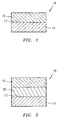
- FIG. 1 is a schematic representation of a turbine engine component with the coating of the present invention; and
- FIG. 2 is a schematic representation of a turbine engine component with an alternative coating system in accordance with the present invention.
- It has been discovered that certain coatings react with fluid sand deposits and a reaction product forms that inhibits fluid sand penetration into the coating. The reaction product has been identified as being a silicate oxyapatite/garnet containing primarily gadolinia, calcia, zirconia, and silica. The present invention relates to a coating system for a component, such as a turbine engine component, which takes advantage of this discovery.
- In accordance with the present invention, referring now to FIG. 1, the
coating system 18 of the present invention includes at least one layer of a material selected from the group consisting of a zirconate, a hafnate, a titanate, and mixtures thereof, which material has been doped with from about 25 - 100 wt% of at least one oxide. In order to form thecoating system 18, at least onelayer 10 of a material selected from the group consisting of a zirconate, a hafnate, a titanate, and mixtures thereof, is applied to asurface 12 of asubstrate 14, such as a turbine engine component including, but not limited to, a blade or a vane. Materials which can be used to form eachlayer 10 include, but are not limited to, gadolinium zirconate, lanthanum zirconate, neodymium titanate, and gadolinium hafnate. The material in eachlayer 10 is mixed with, and preferably contains, from about 25 to 99 wt%, preferably from about 40 - 70 wt%, of at least one oxide of a metal selected from the group consisting of lanthanum, cerium, praseodymium, neodymium, promethium, samarium, europium, gadolinium, terbium, dysprosium, holmium, erbium, thulium, ytterbium, lutetium, scandium, indium, and yttrium. For example, the at least one oxide could be a sesquioxide of one of the aforementioned rare earth elements. - The
substrate 14 may be formed from any suitable material such as a nickel based superalloy, a cobalt based alloy, a moldybdenum based alloy, or a titanium based alloy. - Each
layer 10 may be applied by, for example, electron beam physical vapor deposition (EB-PVD) or air plasma spray. Other methods which can be used to deposit eachlayer 10 includes, but is not limited to, sol-gel techniques, slurry techniques, sputtering techniques, chemical vapor deposition techniques, HVOF, and UV curable resin techniques. - A preferred process for performing the deposition of each
layer 10 is EB-PVD. When performing this process, thesubstrate 14 may be placed in a coating chamber and heated to a temperature in the range of from 1700 to 2000 degrees Fahrenheit (927°C to 1093°C). The coating chamber may be maintained at a pressure in the range of from 0.05 to 2.0 millitorrs. The feedstock feed rate may be from 0.3 to 2.0 inches/hour (7.62 to 50.8 mm/hr). The coating time may be in the range of from 20 to 120 minutes. - Each deposited
layer 10 may have a thickness of from about 1.0 to 50 mils (0.025 to 1.27 mm), preferably from about 1.0 to 15 mils (0.025 to 0.381 mm). - The layer(s) 10 of the thermal barrier coating material in accordance with the present invention will react with molten sand deposits and form a barrier phase of oxyapatite and/or garnet to resist further penetration.
- The coating system of the present invention is an advantageous thermal barrier coating system that resists the penetration of molten silicate material. The coating system provides enhanced durability in environments where sand induced distress of turbine airfoils occurs.
- Referring now to FIG. 2, if desired, a
metallic bond coat 30 may be deposited onto thesubstrate 14 to bond thesubstrate 14 to thelayer 10. Themetallic bond coat 30 may be a MCrAlY bond coat where M is at least one of nickel, cobalt, and iron. Alternatively, themetallic bond coat 30 may be an aluminide or platinum aluminide bond coat. Thebond coat 30 may have a thickness in the range of from about 0.5 to 20 mils (0.013 to 0.508 mm), preferably from about 0.5 to 10 mils (0.013 to 0.254 mm). Thebond coat 30 may be deposited by a low pressure plasma spray, HVOF (high velocity oxygen fuel), a cathodic arc process, a diffusion process, an air plasma spray process, or a plating process, as well as by any process which is capable of forming a dense uniform metallic structure.
Claims (22)
- A turbine engine component comprising:a substrate (14); anda thermal barrier coating system (18) comprising at least one layer (10) of a material selected from the group consisting of a zirconate, a hafnate, a titanate, and mixtures thereof, which material has been mixed with at least one oxide so that each said layer contains from about 25 to 99 wt% of said at least one oxide.
- The turbine engine component of claim 1, wherein each said layer (10) contains from about 40 to 70 wt% of said at least one oxide.
- The turbine engine component of claim 1 or 2, wherein said material is selected from the group consisting of gadolinium zirconate, lanthanum zirconate, neodymium titanate, and gadolinium hafnate.
- The turbine engine component according to any preceding claim, wherein said at least one oxide comprises at least one oxide of a material selected from the group consisting of lanthanum, cerium, praseodymium, neodymium, promethium, samarium, europium, gadolinium, terbium, dysprosium, holmium, erbium, thulium, ytterbium, lutetium, scandium, indium, and yttrium.
- The turbine engine component according to any preceding claim, wherein each said layer (10) has a thickness in the range of from 1.0 to 50 mils (0.025 to 1.27 mm).
- The turbine engine component according to claim 5, wherein each said layer (10) has a thickness in the range of from 1.0 to 15 mils (0.025 to 0.381 mm).
- The turbine engine component according to any preceding claim, wherein said substrate (14) is formed from a material selected from the group consisting of a nickel based alloy, a cobalt based alloy, and a molybdenum based alloy and further comprising a metallic bond coat (30) between said substrate (14) and said thermal barrier coating (10).
- The turbine engine component according to claim 7, wherein said bond coat (30) has a thickness in the range of from about 0.5 to 20 mils (0.013 to 0.508 mm).
- The turbine engine component according to claim 8, wherein said bond coat (30) has a thickness in the range of from about 0.5 to 10 mils (0.013 to 0.254 mm).
- A method for providing a component with protection against sand related distress comprising the steps of:providing a substrate (14);forming a thermal barrier coating system (18) by depositing at least one layer (10) of a first material selected from the group consisting of a zirconate, a hafnate, a titanate, and mixtures thereof, which first material has been mixed with at least one oxide so that each said layer contains from about 25 to 99 wt% of said at least one oxide.
- The method according to claim 10, wherein said depositing step comprises depositing at least one layer (10) of said first material, which first material has been doped with from about 40 wt% to 70 wt% of said at least one oxide.
- The method according to claim 10 or 11, wherein said depositing step comprises depositing a material selected from the group consisting of gadolinium zirconate, lanthanum zirconate, neodymium titanate, and gadolinium hafnate.
- The method according to claim 10 or 11, wherein said depositing step further comprises selecting said at least one oxide from at least one oxide of a material selected from the group consisting of lanthanum, cerium, praseodymium, neodymium, promethium, samarium, europium, gadolinium, terbium, dysprosium, holmium, erbium, thulium, ytterbium, lutetium, scandium, indium, and yttrium and mixing said first material with said at least one selected oxide.
- The method according to any of claims 10 to 13, wherein said depositing step comprises depositing each said layer (10) to a thickness in the range of from about 1.0 to 50 mils (0.025 to 1.27 mm).
- The method according to claim 14, wherein said depositing step comprises depositing each said layer to a thickness in the range of from about 1.0 to 15 mils (0.025 to 0.381 mm).
- The method according to any of claims 10 to 15, wherein said substrate providing step comprises providing a substrate (14) formed from a material selected from the group consisting of a nickel based alloy, a cobalt based alloy, and a molybdenum based alloy.
- The method according to any of claims 10 to 16, further comprising:placing said substrate (14) into a coating chamber;heating said substrate in said coating chamber to a temperature in the range of from 1700 to 2000°F (927°C to 1093°C);maintaining pressure in said coating chamber at a pressure in the range of from 0.05 to 2.0 millitorrs; andperforming said depositing step.
- The method according to any of claims 10 to 17, further comprising depositing a metallic bond coat layer between said substrate (14) and said thermal barrier coating system (18).
- A coating system for a component comprising at least one layer (10) of a first material selected from the group consisting of a zirconate, a hafnate, a titanate, and mixtures thereof, which first material has been mixed with at least one oxide so that each said layer contains from about 25 to 99 wt% of said at least one oxide.
- The coating system according to claim 19, wherein each said layer (10) contains from about 40 wt% to 70 wt% of said at least one oxide.
- The coating system according to claim 19 or 20, wherein said material is selected from the group consisting of gadolinium zirconate, lanthanum zirconate, neodymium titanate, and gadolinium hafnate.
- The coating system according to claim 19, 20 or 21 wherein said at least one oxide comprises at least one oxide of a material selected from the group consisting of lanthanum, cerium, praseodymium, neodymium, promethium, samarium, europium, gadolinium, terbium, dysprosium, holmium, erbium, thulium, ytterbium, lutetium, scandium, indium, and yttrium.
Applications Claiming Priority (1)
| Application Number | Priority Date | Filing Date | Title |
|---|---|---|---|
| US11/336,437 US7662489B2 (en) | 2006-01-20 | 2006-01-20 | Durable reactive thermal barrier coatings |
Publications (2)
| Publication Number | Publication Date |
|---|---|
| EP1820879A1 true EP1820879A1 (en) | 2007-08-22 |
| EP1820879B1 EP1820879B1 (en) | 2012-08-08 |
Family
ID=37897273
Family Applications (1)
| Application Number | Title | Priority Date | Filing Date |
|---|---|---|---|
| EP07250209A Active EP1820879B1 (en) | 2006-01-20 | 2007-01-19 | Durable reactive thermal barrier coatings |
Country Status (8)
| Country | Link |
|---|---|
| US (2) | US7662489B2 (en) |
| EP (1) | EP1820879B1 (en) |
| JP (1) | JP2007191793A (en) |
| KR (1) | KR20070077055A (en) |
| CN (1) | CN101024738A (en) |
| IL (1) | IL179341A0 (en) |
| SG (1) | SG134216A1 (en) |
| TW (1) | TW200732484A (en) |
Families Citing this family (19)
| Publication number | Priority date | Publication date | Assignee | Title |
|---|---|---|---|---|
| US7875370B2 (en) * | 2006-08-18 | 2011-01-25 | United Technologies Corporation | Thermal barrier coating with a plasma spray top layer |
| US8343591B2 (en) * | 2008-10-24 | 2013-01-01 | United Technologies Corporation | Method for use with a coating process |
| US20100227146A1 (en) * | 2009-03-06 | 2010-09-09 | Larose Joel | Thermal barrier coating with lower thermal conductivity |
| US8481117B2 (en) * | 2010-03-08 | 2013-07-09 | United Technologies Corporation | Method for applying a thermal barrier coating |
| DE102010050771B4 (en) * | 2010-11-10 | 2014-05-08 | Schott Ag | Product of glass or glass-ceramic with high-temperature stable low-energy layer, method of making same and use of the product |
| US12529321B2 (en) | 2013-10-02 | 2026-01-20 | Rtx Corporation | Segmented ceramic coating interlayer |
| EP3052787B1 (en) | 2013-10-02 | 2021-12-15 | Raytheon Technologies Corporation | Air seal system and method for forming an air seal system |
| US9920417B2 (en) | 2014-10-27 | 2018-03-20 | General Electric Company | Article and method of making thereof |
| US9790587B2 (en) | 2014-10-28 | 2017-10-17 | General Electric Company | Article and method of making thereof |
| US9869188B2 (en) | 2014-12-12 | 2018-01-16 | General Electric Company | Articles for high temperature service and method for making |
| US10221703B2 (en) | 2015-11-24 | 2019-03-05 | General Electric Company | Articles having damage-tolerant thermal barrier coating |
| US10822966B2 (en) | 2016-05-09 | 2020-11-03 | General Electric Company | Thermal barrier system with bond coat barrier |
| CN108018516A (en) * | 2016-10-31 | 2018-05-11 | 通用电气公司 | Kinds of anti-sulfur corrosion coating, includes its object, and uses its method |
| US10822696B2 (en) | 2016-12-14 | 2020-11-03 | General Electric Company | Article with thermal barrier coating and method for making |
| US10294962B2 (en) * | 2017-06-30 | 2019-05-21 | United Technologies Corporation | Turbine engine seal for high erosion environment |
| CN112481577B (en) * | 2020-11-18 | 2021-12-21 | 东北大学 | Thermal shock resistant thermal barrier coating material and preparation method thereof |
| CN117107188A (en) * | 2023-08-29 | 2023-11-24 | 中国科学院上海硅酸盐研究所 | Corrosion-resistant rare earth hafnate coating structure and preparation method thereof |
| KR102779730B1 (en) * | 2024-05-03 | 2025-03-10 | 경북대학교 산학협력단 | Polymer composite emitting near infrared ray and near-infrared emitting commodities comprising the same |
| CN118996334A (en) * | 2024-08-09 | 2024-11-22 | 中国航发北京航空材料研究院 | Gadolinium-zirconium-europium-oxygen thermal barrier coating material and preparation method thereof |
Citations (4)
| Publication number | Priority date | Publication date | Assignee | Title |
|---|---|---|---|---|
| EP0825271A1 (en) * | 1996-08-16 | 1998-02-25 | ROLLS-ROYCE plc | A metallic article having a thermal barrier coating and a method of application thereof |
| US6261643B1 (en) * | 1997-04-08 | 2001-07-17 | General Electric Company | Protected thermal barrier coating composite with multiple coatings |
| US6284323B1 (en) * | 1996-12-12 | 2001-09-04 | United Technologies Corporation | Thermal barrier coating systems and materials |
| US20020028344A1 (en) * | 1996-12-10 | 2002-03-07 | Wolfram Beele | Thermal barrier layer and process for producing the same |
Family Cites Families (8)
| Publication number | Priority date | Publication date | Assignee | Title |
|---|---|---|---|---|
| US6835465B2 (en) * | 1996-12-10 | 2004-12-28 | Siemens Westinghouse Power Corporation | Thermal barrier layer and process for producing the same |
| JP2001521988A (en) * | 1997-11-03 | 2001-11-13 | シーメンス アクチエンゲゼルシヤフト | Products, especially structural members of gas turbines with ceramic insulation layers |
| US6723674B2 (en) * | 2000-09-22 | 2004-04-20 | Inframat Corporation | Multi-component ceramic compositions and method of manufacture thereof |
| US6812176B1 (en) * | 2001-01-22 | 2004-11-02 | Ohio Aerospace Institute | Low conductivity and sintering-resistant thermal barrier coatings |
| US6890668B2 (en) * | 2002-08-30 | 2005-05-10 | General Electric Company | Thermal barrier coating material |
| US6875529B1 (en) * | 2003-12-30 | 2005-04-05 | General Electric Company | Thermal barrier coatings with protective outer layer for improved impact and erosion resistance |
| US20070160859A1 (en) * | 2006-01-06 | 2007-07-12 | General Electric Company | Layered thermal barrier coatings containing lanthanide series oxides for improved resistance to CMAS degradation |
| US7579087B2 (en) * | 2006-01-10 | 2009-08-25 | United Technologies Corporation | Thermal barrier coating compositions, processes for applying same and articles coated with same |
-
2006
- 2006-01-20 US US11/336,437 patent/US7662489B2/en active Active
- 2006-11-16 IL IL179341A patent/IL179341A0/en unknown
- 2006-11-23 TW TW095143429A patent/TW200732484A/en unknown
- 2006-12-12 SG SG200608677-1A patent/SG134216A1/en unknown
- 2006-12-22 KR KR1020060132257A patent/KR20070077055A/en not_active Ceased
-
2007
- 2007-01-17 JP JP2007007568A patent/JP2007191793A/en active Pending
- 2007-01-19 CN CNA2007100073036A patent/CN101024738A/en active Pending
- 2007-01-19 EP EP07250209A patent/EP1820879B1/en active Active
-
2009
- 2009-12-18 US US12/641,521 patent/US8343587B2/en active Active
Patent Citations (4)
| Publication number | Priority date | Publication date | Assignee | Title |
|---|---|---|---|---|
| EP0825271A1 (en) * | 1996-08-16 | 1998-02-25 | ROLLS-ROYCE plc | A metallic article having a thermal barrier coating and a method of application thereof |
| US20020028344A1 (en) * | 1996-12-10 | 2002-03-07 | Wolfram Beele | Thermal barrier layer and process for producing the same |
| US6284323B1 (en) * | 1996-12-12 | 2001-09-04 | United Technologies Corporation | Thermal barrier coating systems and materials |
| US6261643B1 (en) * | 1997-04-08 | 2001-07-17 | General Electric Company | Protected thermal barrier coating composite with multiple coatings |
Also Published As
| Publication number | Publication date |
|---|---|
| CN101024738A (en) | 2007-08-29 |
| IL179341A0 (en) | 2007-05-15 |
| US20080138658A1 (en) | 2008-06-12 |
| JP2007191793A (en) | 2007-08-02 |
| SG134216A1 (en) | 2007-08-29 |
| US8343587B2 (en) | 2013-01-01 |
| US7662489B2 (en) | 2010-02-16 |
| TW200732484A (en) | 2007-09-01 |
| EP1820879B1 (en) | 2012-08-08 |
| US20100098865A1 (en) | 2010-04-22 |
| KR20070077055A (en) | 2007-07-25 |
Similar Documents
| Publication | Publication Date | Title |
|---|---|---|
| US8343587B2 (en) | Process of forming durable reactive thermal barrier coatings | |
| US7785722B2 (en) | CMAS resistant thermal barrier coating | |
| US8080283B2 (en) | Method for forming a yttria-stabilized zirconia coating with a molten silicate resistant outer layer | |
| US7722959B2 (en) | Silicate resistant thermal barrier coating with alternating layers | |
| EP2208805B1 (en) | Strain tolerant thermal barrier coating system | |
| EP1889949B1 (en) | Sodium containing thermal barrier coating | |
| EP1889940B1 (en) | Thermal barrier coating with a plasma spray top layer | |
| EP1806436A1 (en) | Thermal barrier coating compositions, processes for applying same and articles coated with same | |
| EP2947173B1 (en) | Calcium magnesium aluminosilicate (cmas) resistant thermal barrier coating and coating process therefor | |
| US20190330746A1 (en) | Protection of components from corrosion | |
| US20140030497A1 (en) | Localized transitional coating of turbine components |
Legal Events
| Date | Code | Title | Description |
|---|---|---|---|
| PUAI | Public reference made under article 153(3) epc to a published international application that has entered the european phase |
Free format text: ORIGINAL CODE: 0009012 |
|
| AK | Designated contracting states |
Kind code of ref document: A1 Designated state(s): AT BE BG CH CY CZ DE DK EE ES FI FR GB GR HU IE IS IT LI LT LU LV MC NL PL PT RO SE SI SK TR |
|
| AX | Request for extension of the european patent |
Extension state: AL BA HR MK YU |
|
| 17P | Request for examination filed |
Effective date: 20071015 |
|
| 17Q | First examination report despatched |
Effective date: 20071120 |
|
| AKX | Designation fees paid |
Designated state(s): DE GB |
|
| GRAP | Despatch of communication of intention to grant a patent |
Free format text: ORIGINAL CODE: EPIDOSNIGR1 |
|
| GRAS | Grant fee paid |
Free format text: ORIGINAL CODE: EPIDOSNIGR3 |
|
| GRAA | (expected) grant |
Free format text: ORIGINAL CODE: 0009210 |
|
| AK | Designated contracting states |
Kind code of ref document: B1 Designated state(s): DE GB |
|
| REG | Reference to a national code |
Ref country code: GB Ref legal event code: FG4D Ref country code: DE Ref legal event code: R081 Ref document number: 602007024521 Country of ref document: DE Owner name: UNITED TECHNOLOGIES CORP. (N.D.GES.D. STAATES , US Free format text: FORMER OWNER: UNITED TECHNOLOGIES INC., HARTFORD, CONN., US |
|
| REG | Reference to a national code |
Ref country code: DE Ref legal event code: R096 Ref document number: 602007024521 Country of ref document: DE Effective date: 20121011 |
|
| PLBE | No opposition filed within time limit |
Free format text: ORIGINAL CODE: 0009261 |
|
| STAA | Information on the status of an ep patent application or granted ep patent |
Free format text: STATUS: NO OPPOSITION FILED WITHIN TIME LIMIT |
|
| 26N | No opposition filed |
Effective date: 20130510 |
|
| REG | Reference to a national code |
Ref country code: DE Ref legal event code: R097 Ref document number: 602007024521 Country of ref document: DE Effective date: 20130510 |
|
| REG | Reference to a national code |
Ref country code: DE Ref legal event code: R082 Ref document number: 602007024521 Country of ref document: DE Representative=s name: SCHMITT-NILSON SCHRAUD WAIBEL WOHLFROM PATENTA, DE |
|
| REG | Reference to a national code |
Ref country code: DE Ref legal event code: R082 Ref document number: 602007024521 Country of ref document: DE Representative=s name: SCHMITT-NILSON SCHRAUD WAIBEL WOHLFROM PATENTA, DE Ref country code: DE Ref legal event code: R081 Ref document number: 602007024521 Country of ref document: DE Owner name: UNITED TECHNOLOGIES CORP. (N.D.GES.D. STAATES , US Free format text: FORMER OWNER: UNITED TECHNOLOGIES CORPORATION, HARTFORD, CONN., US |
|
| REG | Reference to a national code |
Ref country code: DE Ref legal event code: R081 Ref document number: 602007024521 Country of ref document: DE Owner name: RAYTHEON TECHNOLOGIES CORPORATION (N.D.GES.D.S, US Free format text: FORMER OWNER: UNITED TECHNOLOGIES CORP. (N.D.GES.D. STAATES DELAWARE), FARMINGTON, CONN., US Ref country code: DE Ref legal event code: R081 Ref document number: 602007024521 Country of ref document: DE Owner name: RTX CORPORATION (N.D.GES.D. STAATES DELAWARE),, US Free format text: FORMER OWNER: UNITED TECHNOLOGIES CORP. (N.D.GES.D. STAATES DELAWARE), FARMINGTON, CONN., US |
|
| P01 | Opt-out of the competence of the unified patent court (upc) registered |
Effective date: 20230519 |
|
| PGFP | Annual fee paid to national office [announced via postgrant information from national office to epo] |
Ref country code: GB Payment date: 20241219 Year of fee payment: 19 |
|
| PGFP | Annual fee paid to national office [announced via postgrant information from national office to epo] |
Ref country code: DE Payment date: 20241218 Year of fee payment: 19 |
|
| REG | Reference to a national code |
Ref country code: DE Ref legal event code: R081 Ref document number: 602007024521 Country of ref document: DE Owner name: RTX CORPORATION (N.D.GES.D. STAATES DELAWARE),, US Free format text: FORMER OWNER: RAYTHEON TECHNOLOGIES CORPORATION (N.D.GES.D.STAATES DELAWARE), ARLINGTON, VA, US |