EP1820872B1 - Process of preparing turbine blades with a masking strip having a connector for a subsequent treatment, and turbine blade therefor - Google Patents
Process of preparing turbine blades with a masking strip having a connector for a subsequent treatment, and turbine blade therefor Download PDFInfo
- Publication number
- EP1820872B1 EP1820872B1 EP06000401A EP06000401A EP1820872B1 EP 1820872 B1 EP1820872 B1 EP 1820872B1 EP 06000401 A EP06000401 A EP 06000401A EP 06000401 A EP06000401 A EP 06000401A EP 1820872 B1 EP1820872 B1 EP 1820872B1
- Authority
- EP
- European Patent Office
- Prior art keywords
- plug
- airfoil
- turbine blade
- connection
- covering strip
- Prior art date
- Legal status (The legal status is an assumption and is not a legal conclusion. Google has not performed a legal analysis and makes no representation as to the accuracy of the status listed.)
- Not-in-force
Links
Images

Classifications
-
- F—MECHANICAL ENGINEERING; LIGHTING; HEATING; WEAPONS; BLASTING
- F01—MACHINES OR ENGINES IN GENERAL; ENGINE PLANTS IN GENERAL; STEAM ENGINES
- F01D—NON-POSITIVE DISPLACEMENT MACHINES OR ENGINES, e.g. STEAM TURBINES
- F01D25/00—Component parts, details, or accessories, not provided for in, or of interest apart from, other groups
- F01D25/28—Supporting or mounting arrangements, e.g. for turbine casing
- F01D25/285—Temporary support structures, e.g. for testing, assembling, installing, repairing; Assembly methods using such structures
-
- C—CHEMISTRY; METALLURGY
- C23—COATING METALLIC MATERIAL; COATING MATERIAL WITH METALLIC MATERIAL; CHEMICAL SURFACE TREATMENT; DIFFUSION TREATMENT OF METALLIC MATERIAL; COATING BY VACUUM EVAPORATION, BY SPUTTERING, BY ION IMPLANTATION OR BY CHEMICAL VAPOUR DEPOSITION, IN GENERAL; INHIBITING CORROSION OF METALLIC MATERIAL OR INCRUSTATION IN GENERAL
- C23C—COATING METALLIC MATERIAL; COATING MATERIAL WITH METALLIC MATERIAL; SURFACE TREATMENT OF METALLIC MATERIAL BY DIFFUSION INTO THE SURFACE, BY CHEMICAL CONVERSION OR SUBSTITUTION; COATING BY VACUUM EVAPORATION, BY SPUTTERING, BY ION IMPLANTATION OR BY CHEMICAL VAPOUR DEPOSITION, IN GENERAL
- C23C4/00—Coating by spraying the coating material in the molten state, e.g. by flame, plasma or electric discharge
- C23C4/12—Coating by spraying the coating material in the molten state, e.g. by flame, plasma or electric discharge characterised by the method of spraying
- C23C4/123—Spraying molten metal
-
- C—CHEMISTRY; METALLURGY
- C23—COATING METALLIC MATERIAL; COATING MATERIAL WITH METALLIC MATERIAL; CHEMICAL SURFACE TREATMENT; DIFFUSION TREATMENT OF METALLIC MATERIAL; COATING BY VACUUM EVAPORATION, BY SPUTTERING, BY ION IMPLANTATION OR BY CHEMICAL VAPOUR DEPOSITION, IN GENERAL; INHIBITING CORROSION OF METALLIC MATERIAL OR INCRUSTATION IN GENERAL
- C23C—COATING METALLIC MATERIAL; COATING MATERIAL WITH METALLIC MATERIAL; SURFACE TREATMENT OF METALLIC MATERIAL BY DIFFUSION INTO THE SURFACE, BY CHEMICAL CONVERSION OR SUBSTITUTION; COATING BY VACUUM EVAPORATION, BY SPUTTERING, BY ION IMPLANTATION OR BY CHEMICAL VAPOUR DEPOSITION, IN GENERAL
- C23C4/00—Coating by spraying the coating material in the molten state, e.g. by flame, plasma or electric discharge
- C23C4/12—Coating by spraying the coating material in the molten state, e.g. by flame, plasma or electric discharge characterised by the method of spraying
- C23C4/134—Plasma spraying
-
- C—CHEMISTRY; METALLURGY
- C23—COATING METALLIC MATERIAL; COATING MATERIAL WITH METALLIC MATERIAL; CHEMICAL SURFACE TREATMENT; DIFFUSION TREATMENT OF METALLIC MATERIAL; COATING BY VACUUM EVAPORATION, BY SPUTTERING, BY ION IMPLANTATION OR BY CHEMICAL VAPOUR DEPOSITION, IN GENERAL; INHIBITING CORROSION OF METALLIC MATERIAL OR INCRUSTATION IN GENERAL
- C23C—COATING METALLIC MATERIAL; COATING MATERIAL WITH METALLIC MATERIAL; SURFACE TREATMENT OF METALLIC MATERIAL BY DIFFUSION INTO THE SURFACE, BY CHEMICAL CONVERSION OR SUBSTITUTION; COATING BY VACUUM EVAPORATION, BY SPUTTERING, BY ION IMPLANTATION OR BY CHEMICAL VAPOUR DEPOSITION, IN GENERAL
- C23C4/00—Coating by spraying the coating material in the molten state, e.g. by flame, plasma or electric discharge
- C23C4/18—After-treatment
- C23C4/185—Separation of the coating from the substrate
-
- Y—GENERAL TAGGING OF NEW TECHNOLOGICAL DEVELOPMENTS; GENERAL TAGGING OF CROSS-SECTIONAL TECHNOLOGIES SPANNING OVER SEVERAL SECTIONS OF THE IPC; TECHNICAL SUBJECTS COVERED BY FORMER USPC CROSS-REFERENCE ART COLLECTIONS [XRACs] AND DIGESTS
- Y02—TECHNOLOGIES OR APPLICATIONS FOR MITIGATION OR ADAPTATION AGAINST CLIMATE CHANGE
- Y02T—CLIMATE CHANGE MITIGATION TECHNOLOGIES RELATED TO TRANSPORTATION
- Y02T50/00—Aeronautics or air transport
- Y02T50/60—Efficient propulsion technologies, e.g. for aircraft
-
- Y—GENERAL TAGGING OF NEW TECHNOLOGICAL DEVELOPMENTS; GENERAL TAGGING OF CROSS-SECTIONAL TECHNOLOGIES SPANNING OVER SEVERAL SECTIONS OF THE IPC; TECHNICAL SUBJECTS COVERED BY FORMER USPC CROSS-REFERENCE ART COLLECTIONS [XRACs] AND DIGESTS
- Y10—TECHNICAL SUBJECTS COVERED BY FORMER USPC
- Y10T—TECHNICAL SUBJECTS COVERED BY FORMER US CLASSIFICATION
- Y10T29/00—Metal working
- Y10T29/49—Method of mechanical manufacture
- Y10T29/49316—Impeller making
- Y10T29/49336—Blade making
Definitions
- the invention relates to a method for the preparation of turbine blades for a subsequent treatment, for example the application of a coating and / or abrasive machining, wherein the turbine blade has an airfoil bounded on at least one end by an end plate with peripheral surfaces, wherein at least one of Peripheral surfaces is at least partially covered before the treatment of the turbine blade.
- the invention further relates to a turbine blade having an airfoil that is delimited at at least one end by an endplate having a hot gas side facing the airfoil and adjoining peripheral surfaces.
- Turbine blades such as guide vanes and rotor blades, which are intended for gas turbines, are coated to improve their temperature and / or abrasion resistance with suitable metals, metal alloys or ceramics.
- the coating is done by means of a spray coating device in which the turbine blade is spray-coated.
- spray coating methods are atmospheric plasma spraying (APS) and high-speed oxygen-fuel spraying (HVOF) (cf. Ullmann's Encyclopedia of Industrial Chemistry, 2003, Vol. 21, pp. 573 and 575 ).
- turbine blades one differentiates between guide vanes and rotor blades. Both have an airfoil exposed to the hot gas, which merges at a front end into a base which serves to secure the turbine blade to either a rotor (bucket) or a support (vane).
- a vane has at the other end of the airfoil in addition to a head body, which is like the foot intended for attachment to a holder. Foot and head form at the transition to the blade end plates in the form of foot plates or top plates from, which have a the hot air side facing the airfoil and adjoining peripheral surfaces.
- the above-described coating is carried out only on those surfaces which are exposed to the hot gas, that is, the airfoil and the hot gas sides of foot and optionally top plate.
- the peripheral surfaces of these end plates and the remaining parts of the foot and possibly head body must remain free of coating according to specifications, because they have already been brought mechanically to final gauge.
- the spray coating device therefore, the foot body and optionally the head body are covered as well as possible with the exception of the respective hot gas side.
- coating material also reaches the parts of the peripheral surfaces of the end plates which are adjacent to the hot gas side, that is to say a so-called "overspray" occurs. In a subsequent process, this requires removal of the coating by abrading (overspray grinding). There is the danger that even uncoated parts of the peripheral surfaces will be ground and thereby the final dimension will be changed.
- the blade segment is provided with an inner channel, the channel wall is provided with a protective coating.
- a mask part is placed as a cover strip on a front side of the end plate of the blade segment in the previously known method, in order to cover these and in particular the channels provided therein.
- the fixing of the mask part to the end plate takes place via separate holding devices, by which the mask part and the end plate are in particular braced.
- an apparatus and method for covering portions of the surface of a turbine blade during a surface treatment are disclosed.
- the turbine blade is elastically clamped in a device.
- a surface of the turbine blade remote from the airfoil is covered by a deformable surface.
- the surface of the blade root to be protected may comprise an opening in which a projection of a positioning region for fixing the covering device can be inserted.
- the invention has for its object to provide a method by which the peripheral surfaces of the end plates of turbine blades can be protected on the one hand during the coating process and on the other hand in the subsequent overspray grinding. Another object is to design a turbine blade suitable for this purpose.
- the first part of the object is achieved by a method in which a cover strip is placed on at least one peripheral surface to form a connector.
- the basic idea of the invention is thus to protect the peripheral surfaces of the end plate (s) with the aid of cover strips, which are each held on the turbine blade via a plug connection.
- the connector allows a simple and nevertheless secure fixing of the cover in the area of the peripheral surfaces.
- the cover protects the peripheral surfaces during the coating process before spraying with coating material. As far as there is an overspray, so to a coating of a part of the peripheral surfaces, this overspray can be removed after the coating process by grinding when still attached cover strip, the cover protects the uncoated part of the peripheral surfaces. Thus, the risk of falling below the final dimension is significantly reduced.
- a cover strip or a respectively required number of cover strips to be used which, in the plugged-on state, covers the region of the respective peripheral surface which extends on the side of the plug connection facing away from the airfoil. Overspray can then only occur in the part left free by the cover strip.
- peripheral surface (s) and cover strip (s) are adapted to each other in such a way that their plug connection results in a tongue and groove connection.
- This is done in the present case in such a way that in at least one of the peripheral surfaces, a groove is formed and a cover strip is used, which has a Einsteckschenkel which is inserted into the groove.
- the cover strip can be formed as an angle section with a subsequent to the Einsteckschenkel protective leg, it is useful if plug-in and protection legs are at right angles to each other.
- a step is formed in the peripheral surfaces, at least in the region of the plug connection. It can be at the side facing away from the blade Side of the connector, but also project on the side facing the airfoil to the outside.
- the second part of the object is achieved by a turbine blade, wherein at least one of the peripheral surfaces each having at least one plug connection recess.
- a plug-in recess is provided, it is presently designed as a groove.
- the turbine blade can also be designed such that the circumferential surfaces in the region of the plug connection recess or the plug connection projection have a step which protrudes either on the side facing away from the blade leaf or facing the Steckitatisaus supraung or the plug connection projection.
- a cover strip is placed to form a plug connection with the SteckitatisausEnglishung or the connector projection, which advantageously covers the region of the peripheral surface, which is on the side facing away from the blade of the connector extends.
- the connector is designed as a tongue and groove connection. This can be realized in such a way that the cover strip has a Einsteckschenkel, which fits into the at least one Steckitatisaus supraung.
- the cover strip is advantageously designed as an angle section with a subsequent to the Einsteckschenkel angle protective leg. These can form a right angle with each other.
- the length of the cover strip should be greater than the depth of the airfoil.
- the cover strip may be made of a suitable material which is resistant to the upper spray grinding.
- it should consist of a metal such as steel or the like.
- a cover strip should be attached to at least one of the peripheral surfaces of both end plates.
- guide vane 1 is intended for a turbomachine. This may be a gas turbine for an aircraft or a power plant for generating electricity, a steam turbine or a compressor.
- the guide blade 1 has along its extension successively a fastening region 2, an adjoining base plate 3, an airfoil 4 and a subsequent to the blade tip headboard 5, which has an adjacent to the airfoil 4 top plate 6.
- the head part 5 is absent if the turbine blade is designed as a moving blade.
- a blade root 7 is formed, which serves for fastening the guide vane 1 to a disc (not shown).
- the blade root 7 is designed here as a dovetail foot. Other designs as fir-tree foot or hammer head are possible.
- the airfoil 4 has a leading edge 8 and a trailing edge 9 for the medium passing through the turbomachine, which flows past the airfoil 4.
- Conventional blades consist for example of solid metallic materials, in particular superalloys. Such superalloys are for example from EP 1 204 776 B1 . EP 1 306 454 . EP 1 319 729 A1 . WO 99/67435 or WO 00/44949 known; these references are part of the disclosure regarding the chemical composition of the alloy.
- the turbine blade can in this case be manufactured by a casting process, also by directional solidification, by a forging process, by a milling process or combinations thereof.
- the turbine blades are provided with a coating against corrosion or oxidation, eg MCrAlX (M is at least one element of the group iron (Fe), cobalt (Co), nickel (Ni), X is an active element and stands for yttrium (Y) and / or silicon and / or at least one element of the rare earth or hafnium (Hf)).
- M is at least one element of the group iron (Fe), cobalt (Co), nickel (Ni)
- X is an active element and stands for yttrium (Y) and / or silicon and / or at least one element of the rare earth or hafnium (Hf)).
- Such alloys are known from the EP 0 486 489 B1 . EP 0 786 . 017 B1 . EP 0 412 297 B1 or EP 1 306 454 A1 which are to be part of this disclosure with regard to the chemical composition of the alloy.
- a heat-insulating layer may still be present and consists for example of ZrO 2 , Y 2 O 3 -ZrO 2 , ie it is not, partially or completely stabilized by yttrium oxide and / or calcium oxide and / or magnesium oxide.
- suitable coating methods such as electron beam evaporation (EB-PVD), stalk-shaped bodies are produced in the thermal barrier coating or by atmospheric Plasma spraying (APS) produced porous, micro and macro cracked grains in the thermal barrier coating.
- Refurbishment means that components may need to be removed after use (eg by sandblasting). This is followed by removal of the corrosion and / or oxidation layers or products. If necessary, cracks in the component are also repaired. Thereafter, a re-coating and a renewed use of the turbine blade.
- the vane 1 is hollow. She points to the in FIG. 1 Visible pressure side of the airfoil 4 in the region of the trailing edge 9, a series of film cooling holes - for example denoted by 10 - on, can flow through the introduced into the airfoil 4 cooling air, whereby the trailing edge 9 is cooled.
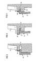
- Each of the hot gas sides 11, 12 is adjoined by four peripheral surfaces 13, 14, 15, 16 and 17, 18, 19, 20, each one corresponding to the base plate 3 and the top plate 6 provided with a stage 21, 22, as they are made FIG. 2 results.
- the steps 21, 22 project outwards relative to the area of the circumferential surfaces 13 to 20 adjacent to the blade 4.
- the steps 21, 22 merge into a circumferential groove 23. Both in the peripheral surfaces 13 to 16 of the base plate 3 and in the peripheral surfaces 17 to 20 of the top plate 6 such grooves 23 are formed.
- the cover strips 24, 25 extend over the entire width of the peripheral surface 13 and 17, respectively. They are in the form of angle profiles, each having a plug-in leg 26 and a protective leg 27, 28 extending at right angles thereto.
- the Einsteckschenkel 26 sit in the grooves 23 and form in this way a plug connection with the base plate 3 and the top plate 6.
- the cover strips 24, 25 are in the grooves 23 used that their protective legs 27, 28 are directed away from the respective hot gas side 11 and 12 and cover the areas of the peripheral surfaces 13 and 17, which - seen from the blade 4 - lie behind the grooves 23.
- the vane 1 is provided with the cover strips 24, 25 in a spray coating device with the coating described above, in such a way that the airfoil 4 and the hot gas sides 11, 12 of the base plate 3 and top plate 6 are coated.
- the coating process also produces an overspray coating 29, 30 on the regions of the peripheral surfaces 13, 17 not covered by the cover strips 24, 25.
- the upper spray coatings 29, 30 are manually abraded after the coating process, with the cover strips 24, 25 attached to the foot plate 3 or. Head plate 6 remain and thus form a protection against slipping of the grinder. In this way, the grinding remains limited to the area carrying the overspray coating 29, 30. Only after grinding the cover strips 24, 25 are removed again and can then be used again.
- FIGS. 3 and 4 show from the embodiment according to the FIGS. 1 and 2 different configurations of peripheral surfaces 31, 32 of foot plates 33, 34.
- a step 35 is formed by projecting the area of the peripheral surface 31 adjacent to the airfoil 4 outward, forming an upper spray coating 36 on this part.
- the step 35 merges into a groove 37, in which the cover strip 24 is inserted with the Einsteckschenkel 26.
- a groove 38 is formed, in which the cover strip 24 is inserted such that its protective leg 27 extends away from the blade 4.
- the region of the peripheral surface 32 adjacent to the airfoil 4 is provided with an overspray coating 39.
Description
Die Erfindung betrifft ein Verfahren zur Vorbereitung von Turbinenschaufeln für eine anschließende Behandlung, beispielsweise das Aufbringen einer Beschichtung und/oder einer abtragenden Bearbeitung, wobei die Turbinenschaufel ein Schaufelblatt aufweist, das an zumindest einem Ende von einer Endplatte mit Umfangsflächen begrenzt wird, wobei zumindest eine der Umfangsflächen vor der Behandlung der Turbinenschaufel wenigstens teilweise abgedeckt wird. Die Erfindung betrifft des Weiteren eine Turbinenschaufel mit einem Schaufelblatt, das an zumindest einem Ende von einer Endplatte begrenzt ist, die eine dem Schaufelblatt zugewandte Heißgasseite und daran anschließende Umfangsflächen aufweist.The invention relates to a method for the preparation of turbine blades for a subsequent treatment, for example the application of a coating and / or abrasive machining, wherein the turbine blade has an airfoil bounded on at least one end by an end plate with peripheral surfaces, wherein at least one of Peripheral surfaces is at least partially covered before the treatment of the turbine blade. The invention further relates to a turbine blade having an airfoil that is delimited at at least one end by an endplate having a hot gas side facing the airfoil and adjoining peripheral surfaces.
Turbinenschaufeln wie Leit- und Laufschaufeln, die für Gasturbinen bestimmt sind, werden zur Verbesserung ihrer Temperatur- und/oder Abrasionsfestigkeit mit hierfür geeigneten Metallen, Metalllegierungen oder Keramiken beschichtet. Die Beschichtung geschieht mittels einer Sprühbeschichtungsvorrichtung, in der die Turbinenschaufel sprühbeschichtet wird. Beispiele für Sprühbeschichtungsverfahren sind das atmosphärische Plasmasprühen (APS) und das Hochgeschwindigkeits-Sauerstoff-Brennstoff-Sprühen (HVOF) (vgl.
Bei Turbinenschaufeln unterscheidet man zwischen Leit- und Laufschaufeln. Beide haben ein dem Heißgas ausgesetztes Schaufelblatt, das an einem stirnseitigen Ende in einen Fußkörper übergeht, der der Befestigung der Turbinenschaufel entweder an einem Rotor (Laufschaufel) oder an einer Halterung (Leitschaufel) dient. Eine Leitschaufel weist am anderen Ende des Schaufelblatts zusätzlich einen Kopfkörper auf, der wie der Fußkörper für die Befestigung an einer Halterung bestimmt ist. Fuß- und Kopfkörper bilden am Übergang zum Schaufelblatt Endplatten in Form von Fußplatten bzw. Kopfplatten aus, die eine dem Schaufelblatt zugewandte Heißgasseite und sich daran anschließende Umfangsflächen aufweisen.With turbine blades one differentiates between guide vanes and rotor blades. Both have an airfoil exposed to the hot gas, which merges at a front end into a base which serves to secure the turbine blade to either a rotor (bucket) or a support (vane). A vane has at the other end of the airfoil in addition to a head body, which is like the foot intended for attachment to a holder. Foot and head form at the transition to the blade end plates in the form of foot plates or top plates from, which have a the hot air side facing the airfoil and adjoining peripheral surfaces.
Die vorbeschriebene Beschichtung wird nur auf denjenigen Flächen vorgenommen, die dem Heißgas ausgesetzt sind, also das Schaufelblatt und die Heißgasseiten von Fuß- und gegebenenfalls Kopfplatte. Die Umfangsflächen dieser Endplatten sowie die übrigen Teile des Fuß- und gegebenenfalls Kopfkörpers müssen spezifikationsgerecht beschichtungsfrei bleiben, weil sie bereits mechanisch auf Endmaß gebracht worden sind. In der Sprühbeschichtungsvorrichtung werden deshalb der Fußkörper und gegebenenfalls der Kopfkörper bis auf die jeweilige Heißgasseite so gut es geht - abgedeckt. Es ist jedoch kaum zu vermeiden, dass Beschichtungsmaterial auch die der Heißgasseite benachbarten Teile der Umfangsflächen der Endplatten erreicht, es also zu einem so genannten "Overspray" kommt. Dies erfordert in einem nachgeschalteten Verfahrensgang ein Entfernen der Beschichtung durch Abschleifen (Oversprayschleifen). Dabei steht die Gefahr, dass auch nicht beschichtete Teile der Umfangsflächen beschliffen werden und hierdurch das Endmaß verändert wird.The above-described coating is carried out only on those surfaces which are exposed to the hot gas, that is, the airfoil and the hot gas sides of foot and optionally top plate. The peripheral surfaces of these end plates and the remaining parts of the foot and possibly head body must remain free of coating according to specifications, because they have already been brought mechanically to final gauge. In the spray coating device, therefore, the foot body and optionally the head body are covered as well as possible with the exception of the respective hot gas side. However, it can hardly be avoided that coating material also reaches the parts of the peripheral surfaces of the end plates which are adjacent to the hot gas side, that is to say a so-called "overspray" occurs. In a subsequent process, this requires removal of the coating by abrading (overspray grinding). There is the danger that even uncoated parts of the peripheral surfaces will be ground and thereby the final dimension will be changed.
In dem Dokument
In dem Dokument
In dem Dokument
Der Erfindung liegt die Aufgabe zugrunde, ein Verfahren bereitzustellen, mit dem die Umfangsflächen der Endplatten von Turbinenschaufeln einerseits beim Beschichtungsvorgang und andererseits beim anschließenden Oversprayschleifen geschützt werden können. Eine weitere Aufgabe besteht darin, eine hierfür geeignete Turbinenschaufel zu konzipieren.The invention has for its object to provide a method by which the peripheral surfaces of the end plates of turbine blades can be protected on the one hand during the coating process and on the other hand in the subsequent overspray grinding. Another object is to design a turbine blade suitable for this purpose.
Der erste Teil der Aufgabe wird erfindungsgemäß durch ein Verfahren gelöst, bei dem auf wenigstens einer Umfangsfläche eine Abdeckleiste unter Bildung einer Steckverbindung aufgesetzt wird. Grundgedanke der Erfindung ist es also, die Umfangsflächen der Endplatte(n) mit Hilfe von Abdeckleisten zu schützen, die jeweils über eine Steckverbindung an der Turbinenschaufel gehaltert werden. Die Steckverbindung erlaubt ein einfaches und gleichwohl sicheres Fixieren der Abdeckleiste im Bereich der Umfangsflächen. Die Abdeckleiste schützt die Umfangsflächen beim Beschichtungsvorgang vor dem Besprühen mit Beschichtungsmaterial. Soweit es zu einem Overspray, also zu einer Beschichtung eines Teils der Umfangsflächen kommt, kann dieser Overspray nach dem Beschichtungsvorgang durch Schleifen bei noch aufgesteckter Abdeckleiste entfernt werden, wobei die Abdeckleiste den nicht beschichteten Teil der Umfangsflächen schützt. Damit wird die Gefahr des Unterschreitens des Endmaßes wesentlich herabgesetzt.The first part of the object is achieved by a method in which a cover strip is placed on at least one peripheral surface to form a connector. The basic idea of the invention is thus to protect the peripheral surfaces of the end plate (s) with the aid of cover strips, which are each held on the turbine blade via a plug connection. The connector allows a simple and nevertheless secure fixing of the cover in the area of the peripheral surfaces. The cover protects the peripheral surfaces during the coating process before spraying with coating material. As far as there is an overspray, so to a coating of a part of the peripheral surfaces, this overspray can be removed after the coating process by grinding when still attached cover strip, the cover protects the uncoated part of the peripheral surfaces. Thus, the risk of falling below the final dimension is significantly reduced.
In Ausbildung der Erfindung ist vorgesehen, dass eine Abdeckleiste bzw. eine jeweils notwendige Anzahl von Abdeckleisten verwendet wird, die im aufgesteckten Zustand den Bereich der jeweiligen Umfangsfläche abdeckt, der sich auf der dem Schaufelblatt abgewandten Seite der Steckverbindung erstreckt. Zu einem Overspray kann es dann nur in dem von der Abdeckleiste freigelassenen Teil kommen.In an embodiment of the invention, provision is made for a cover strip or a respectively required number of cover strips to be used which, in the plugged-on state, covers the region of the respective peripheral surface which extends on the side of the plug connection facing away from the airfoil. Overspray can then only occur in the part left free by the cover strip.
Nach der Erfindung ist ferner vorgeschlagen, dass Umfangsfläche(n) und Abdeckleiste(n) derart aneinander angepasst werden, dass ihre Steckverbindung eine Nut-Feder-Verbindung ergibt. Dies geschieht vorliegend in der Weise, dass in wenigstens eine der Umfangsflächen eine Nut eingeformt wird und eine Abdeckleiste verwendet wird, die einen Einsteckschenkel aufweist, der in die Nut eingesteckt wird. Die Abdeckleiste kann dabei als Winkelprofil mit einem sich an den Einsteckschenkel anschließenden Schutzschenkel ausgebildet sein, wobei es zweckmäßig ist, wenn Einsteck- und Schutzschenkel im rechten Winkel zueinander liegen.According to the invention it is further proposed that the peripheral surface (s) and cover strip (s) are adapted to each other in such a way that their plug connection results in a tongue and groove connection. This is done in the present case in such a way that in at least one of the peripheral surfaces, a groove is formed and a cover strip is used, which has a Einsteckschenkel which is inserted into the groove. The cover strip can be formed as an angle section with a subsequent to the Einsteckschenkel protective leg, it is useful if plug-in and protection legs are at right angles to each other.
Es hat sich als zweckmäßig erwiesen, eine Abdeckleiste zu verwenden, deren Länge größer ist als die Tiefe des Schaufelblattes, so dass die Abdeckleiste einen Überstand hat.It has proven expedient to use a cover strip whose length is greater than the depth of the airfoil, so that the cover strip has a projection.
Nach der Erfindung ist ferner vorgesehen, dass in die Umfangsflächen zumindest im Bereich der Steckverbindung eine Stufe eingeformt wird. Sie kann an der dem Schaufelblatt abgewandten Seite der Steckverbindung, aber auch an der dem Schaufelblatt zugewandten Seite nach außen vorspringen.According to the invention it is further provided that in the peripheral surfaces, at least in the region of the plug connection, a step is formed. It can be at the side facing away from the blade Side of the connector, but also project on the side facing the airfoil to the outside.
Der zweite Teil der Aufgabe wird erfindungsgemäß durch eine Turbinenschaufel gelöst, bei der wenigstens eine der Umfangsflächen jeweils zumindest eine Steckverbindungsausnehmung aufweist. Soweit eine Steckverbindungsausnehmung vorgesehen ist, ist sie vorliegend als Nut ausgebildet.The second part of the object is achieved by a turbine blade, wherein at least one of the peripheral surfaces each having at least one plug connection recess. As far as a plug-in recess is provided, it is presently designed as a groove.
Wie schon oben erwähnt, kann die Turbinenschaufel auch so ausgebildet sein, dass die Umfangsflächen im Bereich der Steckverbindungsausnehmung bzw. dem Steckverbindungsvorsprung eine Stufe aufweisen, die entweder auf der dem Schaufelblatt abgewandten oder zugewandten Seite der Steckverbindungsausnehmung bzw. des Steckverbindungsvorsprungs vorspringt.As already mentioned above, the turbine blade can also be designed such that the circumferential surfaces in the region of the plug connection recess or the plug connection projection have a step which protrudes either on the side facing away from the blade leaf or facing the Steckverbindungsausnehmung or the plug connection projection.
Entsprechend dem Grundgedanken des erfindungsgemäßen Verfahrens ist des weiteren vorgesehen, dass auf wenigstens einer Umfangsfläche eine Abdeckleiste unter Bildung einer Steckverbindung mit der Steckverbindungsausnehmung bzw. dem Steckverbindungsvorsprung aufgesetzt ist, welche vorteilhafterweise den Bereich der Umfangsfläche abdeckt, der sich auf der dem Schaufelblatt abgewandten Seite der Steckverbindung erstreckt. Die Steckverbindung ist als Nut-Feder-Verbindung ausgebildet. Dies kann in der Weise verwirklicht werden, dass die Abdeckleiste einen Einsteckschenkel aufweist, der in die zumindest eine Steckverbindungsausnehmung passt.According to the basic idea of the method according to the invention is further provided that on at least one peripheral surface a cover strip is placed to form a plug connection with the Steckverbindungsausnehmung or the connector projection, which advantageously covers the region of the peripheral surface, which is on the side facing away from the blade of the connector extends. The connector is designed as a tongue and groove connection. This can be realized in such a way that the cover strip has a Einsteckschenkel, which fits into the at least one Steckverbindungsausnehmung.
Die Abdeckleiste ist vorteilhafterweise als Winkelprofil mit einer sich an den Einsteckschenkel im Winkel anschließenden Schutzschenkel ausgebildet. Diese können einen rechten Winkel miteinander bilden. Die Länge der Abdeckleiste sollte größer sein als die Tiefe des Schaufelblattes.The cover strip is advantageously designed as an angle section with a subsequent to the Einsteckschenkel angle protective leg. These can form a right angle with each other. The length of the cover strip should be greater than the depth of the airfoil.
Die Abdeckleiste kann aus einem geeigneten Material bestehen, das widerstandsfähig gegenüber dem Obersprayschleifen ist.The cover strip may be made of a suitable material which is resistant to the upper spray grinding.
Zweckmäßigerweise sollte sie aus einem Metall wie Stahl oder dergleichen bestehen.Conveniently, it should consist of a metal such as steel or the like.
Sofern die Turbinenschaufel als Leitschaufel ausgebildet ist, deren Schaufelblatt an beiden Enden von Endplatten begrenzt ist, sollte auf jeweils zumindest eine der Umfangsflächen beider Endplatten eine Abdeckleiste aufgesteckt sein.If the turbine blade is designed as a guide blade whose blade is delimited at both ends by end plates, a cover strip should be attached to at least one of the peripheral surfaces of both end plates.
In der Zeichnung ist die Erfindung anhand von Ausführungsbeispielen näher veranschaulicht. Es zeigen:
Figur 1- eine perspektivische Ansicht einer Leitschaufel für eine Gasturbine;
- Figur 2
- einen teilweisen Querschnitt durch die Fußplatte der Leitschaufel gemäß
Figur 1 - Figur 3
- einen teilweisen Querschnitt durch eine zweite Variante einer Fußplatte und
- Figur 4
- einen teilweisen Querschnitt durch eine dritte Variante einer Fußplatte.
- FIG. 1
- a perspective view of a guide vane for a gas turbine;
- FIG. 2
- a partial cross section through the base plate of the vane according to
FIG. 1 ; - FIG. 3
- a partial cross section through a second variant of a foot plate and
- FIG. 4
- a partial cross section through a third variant of a foot plate.
Die in
Die Leitschaufel 1 weist entlang ihrer Erstreckung aufeinanderfolgend einen Befestigungsbereich 2, eine daran angrenzende Fußplatte 3, ein Schaufelblatt 4 und ein an deren Schaufelspitze anschließendes Kopfteil 5 auf, das eine an das Schaufelblatt 4 angrenzende Kopfplatte 6 besitzt. Das Kopfteil 5 ist nicht vorhanden, wenn die Turbinenschaufel als Laufschaufel ausgebildet ist.The
Im Befestigungsbereich 2 ist ein Schaufelfuß 7 gebildet, der zur Befestigung der Leitschaufel 1 an einer Scheibe dient (nicht dargestellt). Der Schaufelfuß 7 ist hier als Schwalbenschwanzfuß ausgebildet ist. Andere Ausgestaltungen als Tannenbaumfuß oder Hammerkopf sind möglich. Das Schaufelblatt 4 weist für das die Strömungsmaschine durchsetzende Medium, das an dem Schaufelblatt 4 vorbeiströmt, eine Anströmkante 8 und eine Abströmkante 9 auf.In the mounting portion 2, a
Herkömmliche Schaufeln bestehen beispielsweise aus massiven metallischen Werkstoffen, insbesondere Superlegierungen. Solche Superlegierungen sind beispielsweise aus der
Die Turbinenschaufeln werden mit einer Beschichtung gegen Korrosion oder Oxidation versehen, z.B. MCrAlX (M ist zumindest ein Element der Gruppe Eisen (Fe), Cobalt (Co), Nickel (Ni), X ist ein Aktivelement und steht für Yttrium (Y) und/oder Silicium und/oder zumindest ein Element der Seltenen Erden bzw. Hafnium (Hf)). Solche Legierungen sind bekannt aus der
Auf der MCrAlX-Beschichtung kann noch eine Wärmedämmschicht vorhanden sein und besteht beispielsweise aus ZrO2, Y2O3-ZrO2, d.h. sie ist nicht, teilweise oder vollständig stabilisiert durch Yttriumoxid und/oder Calciumoxid und/oder Magnesiumoxid. Durch geeignete Beschichtungsverfahren wie z.B. Elektronenstrahlverdampfen (EB-PVD) werden stängelförmige Körper in der Wärmedämmschicht erzeugt oder durch atmosphärisches Plasmaspritzen (APS) poröse, mikro- und makrorissbehaftete Körner in der Wärmedämmschicht erzeugt.On the MCrAlX coating, a heat-insulating layer may still be present and consists for example of ZrO 2 , Y 2 O 3 -ZrO 2 , ie it is not, partially or completely stabilized by yttrium oxide and / or calcium oxide and / or magnesium oxide. By suitable coating methods such as electron beam evaporation (EB-PVD), stalk-shaped bodies are produced in the thermal barrier coating or by atmospheric Plasma spraying (APS) produced porous, micro and macro cracked grains in the thermal barrier coating.
Wiederaufarbeitung (Refurbishment) bedeutet, dass Bauteile nach ihrem Einsatz gegebenenfalls von Schutzschichten befreit werden müssen (z.B. durch Sandstrahlen). Danach erfolgt eine Entfernung der Korrosions- und/oder Oxidationsschichten bzw. -produkte. Gegebenenfalls werden auch Risse im Bauteil repariert. Danach erfolgt eine Wiederbeschichtung und ein erneuter Einsatz der Turbinenschaufel.Refurbishment means that components may need to be removed after use (eg by sandblasting). This is followed by removal of the corrosion and / or oxidation layers or products. If necessary, cracks in the component are also repaired. Thereafter, a re-coating and a renewed use of the turbine blade.
Die Leitschaufel 1 ist hohl ausgeführt. Sie weist auf der in
Die Fußplatte 3 und die Kopfplatte 6 haben jeweils eine dem Schaufelblatt 4 zugewandte Heißgasseite 11, 12. An die Heißgasseiten 11, 12 schließen sich jeweils vier Umfangsflächen 13, 14, 15, 16 bzw. 17, 18, 19, 20 an, die jeweils mit einer Stufe 21, 22 versehen sind, wie sie sich auch aus
In die Nuten 23 eingesteckt sind Abdeckleisten 24, 25. Die Abdeckleisten 24, 25 erstrecken sich über die gesamte Breite der Umfangsfläche 13 bzw. 17. Sie sind als Winkelprofile mit jeweils einem Einsteckschenkel 26 und einem jeweils rechtwinklig dazu verlaufenden Schutzschenkel 27, 28 ausgebildet. Die Einsteckschenkel 26 sitzen in den Nuten 23 und bilden auf diese Weise eine Steckverbindung mit der Fußplatte 3 bzw. der Kopfplatte 6. Die Abdeckleisten 24, 25 sind so in die Nuten 23 eingesetzt, dass deren Schutzschenkel 27, 28 von der jeweiligen Heißgasseite 11 bzw. 12 weggerichtet sind und die Bereiche der Umfangsflächen 13 bzw. 17 abdecken, die - von dem Schaufelblatt 4 gesehen - hinter den Nuten 23 liegen.The cover strips 24, 25 extend over the entire width of the
Die Leitschaufel 1 wird mit den Abdeckleisten 24, 25 in einer Sprühbeschichtungsvorrichtung mit der oben beschriebenen Beschichtung versehen, und zwar derart, dass das Schaufelblatt 4 und die Heißgasseiten 11, 12 der Fußplatte 3 bzw. Kopfplatte 6 beschichtet werden. Der Beschichtungsvorgang erzeugt auch eine Overspraybeschichtung 29, 30 auf den von den Abdeckleisten 24, 25 nicht abgedeckten Bereichen der Umfangsflächen 13, 17. Die Oberspraybeschichtungen 29, 30 werden nach dem Beschichtungsvorgang manuell abgeschliffen, wobei die Abdeckleisten 24, 25 an der Fußplatte 3 bzw. Kopfplatte 6 verbleiben und so einen Schutz gegen Abrutschen des Schleifgeräts bilden. Auf diese Weise bleibt das Abschleifen auf den Bereich beschränkt, der die Overspraybeschichtung 29, 30 trägt. Erst nach dem Abschleifen werden die Abdeckleisten 24, 25 wieder entfernt und können dann wieder verwendet werden.The
Die
Bei dem Ausführungsbeispiel gemäß
Claims (20)
- Process for preparing turbine blades or vanes (1) for a subsequent treatment,
for example the application of a coating and/or a material-removing operation,
wherein the turbine blade or vane (1) has an airfoil (4), which is delimited at at least one end by an endplate (3, 6, 33, 34) that has a hot-gas side (11, 12) facing the airfoil (4) and adjoining peripheral surfaces (13-16; 17-20; 31, 32),
wherein at least one of the peripheral surfaces (13-16; 17-20; 31, 32) is at least partially covered prior to the treatment of the turbine blade or vane (1),
characterized
in that a covering strip (24, 25) is placed onto at least one peripheral surface (13, 17, 31, 32) to form a plug connection, wherein peripheral surface(s) (13, 17, 31, 32) and covering strip(s) (24, 25) are matched to one another in such a manner that their plug connection produces a tongue-and-groove connection, and
in that a groove (23, 37, 38) is formed into at least one of the peripheral surfaces (13, 17, 31, 32), and
a covering strip (24, 25)
which has a plug-in limb (26)
that is plugged into the groove
is used. - Process according to Claim 1,
characterized in that
the covering strip (24, 25) used, in the plugged-on state, covers that region of the peripheral surface (13, 17, 31, 32) which extends on the side of the plug connection remote from the airfoil (4). - Process according to Claim 1,
characterized in that
the covering strip (24, 25) used is formed as an angle profiled section with a protective limb (27, 28) adjoining the plug-in limb (26). - Process according to Claim 3,
characterized in that
the covering strip (24, 25) used has its plug-in limb (26) and protective limb (27, 28) at right angles to one another. - Process according to one of Claims 1 to 4,
characterized in that
the covering strip (24, 15) used has a length that is greater than the depth of the airfoil (4). - Process according to one of Claims 1 to 5,
characterized in that
a step (21, 22, 35) is formed into the peripheral surfaces (13-16; 17-20; 31) at least in the region of the plug connection. - Process according to Claim 6,
characterized in that
the step (21, 22) is shaped in such a way that it projects outward on the side of the plug connection remote from the airfoil (4). - Process according to Claim 6,
characterized in that
the step (35) is shaped in such a way that it projects outward on the side of the plug connection facing the airfoil (4). - Turbine blade or vane (1) having an airfoil (4),
which is delimited at at least one end by an endplate (3,6, 33, 34) that has a hot-gas side (11, 12) facing the airfoil (4) and adjoining peripheral surfaces (13-16; 17-20; 31, 32), characterized in that
a covering strip (24, 25) is fitted onto at least one peripheral surface (13, 17, 31, 32) to form a plug connection, formed as a tongue-and-groove connection, to a plug-connection recess (23, 37, 38),
wherein at least one of the peripheral surfaces (13, 17, 31, 32) in each case has at least one plug-connection recess (23, 37, 38) formed as a groove. - Turbine blade or vane according to Claim 9,
characterized in that
the peripheral surfaces (13-16; 17-20; 31) have a step (21, 22, 35) in the region of the plug-connection recess (23, 37) or the plug-connection projection. - Turbine blade or vane according to Claim 10,
characterized in that
the step (21, 22) projects on that side of the plug-connection recess (23) or plug-connection projection which is remote from the airfoil (4). - Turbine blade or vane according to Claim 10,
characterized in that
the step (35) projects on that side of the plug-connection recess (37) or plug-connection projection which is remote from the airfoil (4). - Turbine blade or vane according to Claim 12,
characterized in that
a covering strip (24, 25) is fitted onto at least one peripheral surface (13, 17, 31, 32) to form a plug connection to the plug-connection recess (23, 37, 38) or plug-connection projection. - Turbine blade or vane according to one of Claims 9 to 13,
characterized in that
the covering strip (24, 25) covers that region of the peripheral surface (13, 17, 31, 32) which extends on the side of the plug connection remote from the airfoil (4). - Turbine blade or vane according to Claim 9,
characterized in that
the covering strip (24, 25) has a plug-in limb (26) which fits into the at least one plug-connection recess (23, 37, 38). - Turbine blade or vane according to Claim 15,
characterized in that
the covering strip (24, 25) is formed as an angle profiled section having a protective limb (27, 28) which adjoins the plug-in limb (26) at an angle. - Turbine blade or vane according to Claim 16,
characterized in that
the plug-in limb (26) and protective limb (27, 28) are at right angles to one another. - Turbine blade or vane according to one of Claims 9 to 17,
characterized in that
the length of the covering strip (24, 25) is greater than the depth of the airfoil (4). - Turbine blade or vane according to one of Claims 9 to 18,
characterized in that
the covering strip (24, 25) consists of metal. - Turbine blade or vane according to one of Claims 9 to 19,
characterized in that
the airfoil (4) is delimited at both ends by endplates (3, 6, 33, 34) and a covering strip (24, 25) is fitted onto in each case at least one of the peripheral surfaces (13, 17) of both endplates (3, 6, 33, 34).
Priority Applications (3)
| Application Number | Priority Date | Filing Date | Title |
|---|---|---|---|
| EP06000401A EP1820872B1 (en) | 2006-01-10 | 2006-01-10 | Process of preparing turbine blades with a masking strip having a connector for a subsequent treatment, and turbine blade therefor |
| DE502006008991T DE502006008991D1 (en) | 2006-01-10 | 2006-01-10 | Method for preparing turbine blades with a cover strip with connector for subsequent treatment, and turbine blade therefor |
| US11/651,706 US7922453B2 (en) | 2006-01-10 | 2007-01-10 | Process for preparing turbine blades or vanes for a subsequent treatment, and associated turbine blade or vane |
Applications Claiming Priority (1)
| Application Number | Priority Date | Filing Date | Title |
|---|---|---|---|
| EP06000401A EP1820872B1 (en) | 2006-01-10 | 2006-01-10 | Process of preparing turbine blades with a masking strip having a connector for a subsequent treatment, and turbine blade therefor |
Publications (2)
| Publication Number | Publication Date |
|---|---|
| EP1820872A1 EP1820872A1 (en) | 2007-08-22 |
| EP1820872B1 true EP1820872B1 (en) | 2011-03-02 |
Family
ID=36143373
Family Applications (1)
| Application Number | Title | Priority Date | Filing Date |
|---|---|---|---|
| EP06000401A Not-in-force EP1820872B1 (en) | 2006-01-10 | 2006-01-10 | Process of preparing turbine blades with a masking strip having a connector for a subsequent treatment, and turbine blade therefor |
Country Status (3)
| Country | Link |
|---|---|
| US (1) | US7922453B2 (en) |
| EP (1) | EP1820872B1 (en) |
| DE (1) | DE502006008991D1 (en) |
Families Citing this family (9)
| Publication number | Priority date | Publication date | Assignee | Title |
|---|---|---|---|---|
| US8510925B2 (en) * | 2008-09-04 | 2013-08-20 | Rolls-Royce Corporation | System and method for sealing vacuum in hollow fan blades |
| DE102008053394A1 (en) | 2008-10-27 | 2010-04-29 | Mtu Aero Engines Gmbh | Device for partially covering a component zone |
| EP2181775B1 (en) * | 2008-11-04 | 2012-09-12 | Siemens Aktiengesellschaft | Holder for large components with improved spray protection |
| JP2010150586A (en) * | 2008-12-24 | 2010-07-08 | Toshiba Corp | Ni-based alloy for forged part of steam turbine excellent in high-temperature strength, forgeability and weldability, rotor blade of steam turbine, stator blade of steam turbine, screw member for steam turbine, and pipe for steam turbine |
| US8550776B2 (en) * | 2010-07-28 | 2013-10-08 | General Electric Company | Composite vane mounting |
| US20130047394A1 (en) * | 2011-08-29 | 2013-02-28 | General Electric Company | Solid state system and method for refurbishment of forged components |
| EP3060361B8 (en) * | 2013-10-24 | 2021-04-07 | Raytheon Technologies Corporation | Method of protecting a root of a blade for a gas turbine engine, method of refurbishing said blade and corresponding blade with protective layer |
| DE102013224568A1 (en) * | 2013-11-29 | 2015-06-03 | Siemens Aktiengesellschaft | Method for producing a chamfer, component with chamfer and device |
| US11566298B2 (en) * | 2019-05-08 | 2023-01-31 | Raytheon Technologies Corporation | Systems and methods for manufacturing components for gas turbine engines |
Family Cites Families (16)
| Publication number | Priority date | Publication date | Assignee | Title |
|---|---|---|---|---|
| FR2393931A1 (en) * | 1977-06-08 | 1979-01-05 | Snecma | DEVICE FOR HOLDING THE BLADES OF A ROTOR |
| US4524980A (en) * | 1983-12-05 | 1985-06-25 | United Technologies Corporation | Intersecting feather seals for interlocking gas turbine vanes |
| US4530861A (en) * | 1983-12-19 | 1985-07-23 | General Electric Company | Method and apparatus for masking a surface of a blade member |
| DE8909546U1 (en) | 1989-08-09 | 1989-10-26 | Ringsdorff-Werke Gmbh, 5300 Bonn, De | |
| EP0486489B1 (en) | 1989-08-10 | 1994-11-02 | Siemens Aktiengesellschaft | High-temperature-resistant, corrosion-resistant coating, in particular for components of gas turbines |
| EP0786017B1 (en) | 1994-10-14 | 1999-03-24 | Siemens Aktiengesellschaft | Protective layer for protecting parts against corrosion, oxidation and excessive thermal stresses, as well as process for producing the same |
| WO1999067435A1 (en) | 1998-06-23 | 1999-12-29 | Siemens Aktiengesellschaft | Directionally solidified casting with improved transverse stress rupture strength |
| US6231692B1 (en) | 1999-01-28 | 2001-05-15 | Howmet Research Corporation | Nickel base superalloy with improved machinability and method of making thereof |
| US6171058B1 (en) * | 1999-04-01 | 2001-01-09 | General Electric Company | Self retaining blade damper |
| JP2003529677A (en) | 1999-07-29 | 2003-10-07 | シーメンス アクチエンゲゼルシヤフト | Heat resistant structural member and method of manufacturing the same |
| JP2002201913A (en) * | 2001-01-09 | 2002-07-19 | Mitsubishi Heavy Ind Ltd | Split wall of gas turbine and shroud |
| US6485655B1 (en) | 2001-08-02 | 2002-11-26 | General Electric Company | Method and apparatus for retaining an internal coating during article repair |
| DE50104022D1 (en) | 2001-10-24 | 2004-11-11 | Siemens Ag | Protective layer containing rhenium to protect a component against corrosion and oxidation at high temperatures |
| DE50112339D1 (en) | 2001-12-13 | 2007-05-24 | Siemens Ag | High-temperature resistant component made of monocrystalline or polycrystalline nickel-based superalloy |
| FR2863191B1 (en) * | 2003-12-04 | 2007-04-20 | Snecma Moteurs | PROTECTIVE MASK FOR SURFACE TREATMENT OF TURBOMACHINE BLADES |
| US7484936B2 (en) * | 2005-09-26 | 2009-02-03 | Pratt & Whitney Canada Corp. | Blades for a gas turbine engine with integrated sealing plate and method |
-
2006
- 2006-01-10 DE DE502006008991T patent/DE502006008991D1/en active Active
- 2006-01-10 EP EP06000401A patent/EP1820872B1/en not_active Not-in-force
-
2007
- 2007-01-10 US US11/651,706 patent/US7922453B2/en not_active Expired - Fee Related
Also Published As
| Publication number | Publication date |
|---|---|
| EP1820872A1 (en) | 2007-08-22 |
| US7922453B2 (en) | 2011-04-12 |
| US20100254818A1 (en) | 2010-10-07 |
| DE502006008991D1 (en) | 2011-04-14 |
Similar Documents
| Publication | Publication Date | Title |
|---|---|---|
| EP1820872B1 (en) | Process of preparing turbine blades with a masking strip having a connector for a subsequent treatment, and turbine blade therefor | |
| EP1869290B1 (en) | Component with film cooling holes | |
| DE69924591T2 (en) | Repair of high-pressure scraper rings of turbines | |
| EP2316988B1 (en) | Wear-resistant and oxidation-resistant turbine blade | |
| DE102011057170A1 (en) | Method for producing a film-cooled article | |
| EP2547488B1 (en) | Method for reconditioning a turbine blade with at least one platform | |
| EP1708829A1 (en) | Method for removing a layer | |
| EP1669545A1 (en) | Coating system, use and method of manufacturing such a coating system | |
| EP1707301B1 (en) | Process for applying fibre mats on the surface or a recess of a component | |
| EP1867423A1 (en) | Process for repairing a workpiece through soldering with a sheet coated with solder | |
| EP2604797B1 (en) | Rotor blade with a rib assembly with an abrasive coating | |
| EP1808508A1 (en) | Component located in the flow channel of a turbomachine and spraying process for generating a coating. | |
| DE102019122029A1 (en) | PROTECTING A HOLE IN THE COMPONENT DURING THE COATING PROCESS WITH A PLUG WITH A WATER-SOLUBLE LAYER | |
| WO2005031038A1 (en) | Wear-resistant layer, component comprising such a wear-resistant layer, and production method | |
| DE102007026271A1 (en) | Masking tapes and methods for coating and / or repairing components | |
| EP2984294B1 (en) | Turbine blade with staged and chamfered platform edge | |
| EP2394027A1 (en) | Turbine component having easily removable protective layer, set of turbine components, a turbine and a method for protecting a turbine component | |
| EP2055800B1 (en) | Component holding device for use in a coating facility and method for coating a component | |
| EP1797985A1 (en) | Method and device for welding | |
| DE112020001189T5 (en) | Turbine Blade and Contact Surface Fabrication Process | |
| DE102016207863A1 (en) | Method for processing at least one component region of a component and masking element for partially covering a component to be processed | |
| EP1889680A1 (en) | Process of welding of turbine components using a ceramic core introduced in an hollow part of the turbine component | |
| EP1820873A1 (en) | Method of making turbine components | |
| WO2009053154A1 (en) | Method for removing a metal layer by means of fic in an intermediate step | |
| EP1820939A1 (en) | Method and apparatus for the coating of turbine blades |
Legal Events
| Date | Code | Title | Description |
|---|---|---|---|
| PUAI | Public reference made under article 153(3) epc to a published international application that has entered the european phase |
Free format text: ORIGINAL CODE: 0009012 |
|
| 17P | Request for examination filed |
Effective date: 20061120 |
|
| AK | Designated contracting states |
Kind code of ref document: A1 Designated state(s): AT BE BG CH CY CZ DE DK EE ES FI FR GB GR HU IE IS IT LI LT LU LV MC NL PL PT RO SE SI SK TR |
|
| AX | Request for extension of the european patent |
Extension state: AL BA HR MK YU |
|
| AKX | Designation fees paid |
Designated state(s): CH DE GB IT LI |
|
| 17Q | First examination report despatched |
Effective date: 20080724 |
|
| APBK | Appeal reference recorded |
Free format text: ORIGINAL CODE: EPIDOSNREFNE |
|
| APBN | Date of receipt of notice of appeal recorded |
Free format text: ORIGINAL CODE: EPIDOSNNOA2E |
|
| APBR | Date of receipt of statement of grounds of appeal recorded |
Free format text: ORIGINAL CODE: EPIDOSNNOA3E |
|
| APBV | Interlocutory revision of appeal recorded |
Free format text: ORIGINAL CODE: EPIDOSNIRAPE |
|
| GRAP | Despatch of communication of intention to grant a patent |
Free format text: ORIGINAL CODE: EPIDOSNIGR1 |
|
| GRAS | Grant fee paid |
Free format text: ORIGINAL CODE: EPIDOSNIGR3 |
|
| GRAA | (expected) grant |
Free format text: ORIGINAL CODE: 0009210 |
|
| AK | Designated contracting states |
Kind code of ref document: B1 Designated state(s): CH DE GB IT LI |
|
| REG | Reference to a national code |
Ref country code: GB Ref legal event code: FG4D Free format text: NOT ENGLISH |
|
| REG | Reference to a national code |
Ref country code: CH Ref legal event code: EP |
|
| REF | Corresponds to: |
Ref document number: 502006008991 Country of ref document: DE Date of ref document: 20110414 Kind code of ref document: P |
|
| REG | Reference to a national code |
Ref country code: DE Ref legal event code: R096 Ref document number: 502006008991 Country of ref document: DE Effective date: 20110414 |
|
| REG | Reference to a national code |
Ref country code: CH Ref legal event code: NV Representative=s name: SIEMENS SCHWEIZ AG |
|
| PLBE | No opposition filed within time limit |
Free format text: ORIGINAL CODE: 0009261 |
|
| STAA | Information on the status of an ep patent application or granted ep patent |
Free format text: STATUS: NO OPPOSITION FILED WITHIN TIME LIMIT |
|
| 26N | No opposition filed |
Effective date: 20111205 |
|
| REG | Reference to a national code |
Ref country code: DE Ref legal event code: R097 Ref document number: 502006008991 Country of ref document: DE Effective date: 20111205 |
|
| PGFP | Annual fee paid to national office [announced via postgrant information from national office to epo] |
Ref country code: DE Payment date: 20160321 Year of fee payment: 11 Ref country code: IT Payment date: 20160127 Year of fee payment: 11 |
|
| PGFP | Annual fee paid to national office [announced via postgrant information from national office to epo] |
Ref country code: GB Payment date: 20160111 Year of fee payment: 11 |
|
| PGFP | Annual fee paid to national office [announced via postgrant information from national office to epo] |
Ref country code: CH Payment date: 20160404 Year of fee payment: 11 |
|
| REG | Reference to a national code |
Ref country code: DE Ref legal event code: R119 Ref document number: 502006008991 Country of ref document: DE |
|
| REG | Reference to a national code |
Ref country code: CH Ref legal event code: PL |
|
| GBPC | Gb: european patent ceased through non-payment of renewal fee |
Effective date: 20170110 |
|
| PG25 | Lapsed in a contracting state [announced via postgrant information from national office to epo] |
Ref country code: LI Free format text: LAPSE BECAUSE OF NON-PAYMENT OF DUE FEES Effective date: 20170131 Ref country code: CH Free format text: LAPSE BECAUSE OF NON-PAYMENT OF DUE FEES Effective date: 20170131 |
|
| PG25 | Lapsed in a contracting state [announced via postgrant information from national office to epo] |
Ref country code: DE Free format text: LAPSE BECAUSE OF NON-PAYMENT OF DUE FEES Effective date: 20170801 Ref country code: GB Free format text: LAPSE BECAUSE OF NON-PAYMENT OF DUE FEES Effective date: 20170110 |
|
| PG25 | Lapsed in a contracting state [announced via postgrant information from national office to epo] |
Ref country code: IT Free format text: LAPSE BECAUSE OF NON-PAYMENT OF DUE FEES Effective date: 20170110 |