EP1820719A1 - Molding installation method and device - Google Patents
Molding installation method and device Download PDFInfo
- Publication number
- EP1820719A1 EP1820719A1 EP05809184A EP05809184A EP1820719A1 EP 1820719 A1 EP1820719 A1 EP 1820719A1 EP 05809184 A EP05809184 A EP 05809184A EP 05809184 A EP05809184 A EP 05809184A EP 1820719 A1 EP1820719 A1 EP 1820719A1
- Authority
- EP
- European Patent Office
- Prior art keywords
- molding
- installation
- roller
- jig
- molding installation
- Prior art date
- Legal status (The legal status is an assumption and is not a legal conclusion. Google has not performed a legal analysis and makes no representation as to the accuracy of the status listed.)
- Granted
Links
Images
Classifications
-
- B—PERFORMING OPERATIONS; TRANSPORTING
- B23—MACHINE TOOLS; METAL-WORKING NOT OTHERWISE PROVIDED FOR
- B23P—METAL-WORKING NOT OTHERWISE PROVIDED FOR; COMBINED OPERATIONS; UNIVERSAL MACHINE TOOLS
- B23P19/00—Machines for simply fitting together or separating metal parts or objects, or metal and non-metal parts, whether or not involving some deformation; Tools or devices therefor so far as not provided for in other classes
- B23P19/04—Machines for simply fitting together or separating metal parts or objects, or metal and non-metal parts, whether or not involving some deformation; Tools or devices therefor so far as not provided for in other classes for assembling or disassembling parts
- B23P19/047—Machines for simply fitting together or separating metal parts or objects, or metal and non-metal parts, whether or not involving some deformation; Tools or devices therefor so far as not provided for in other classes for assembling or disassembling parts for flexible profiles, e.g. sealing or decorating strips in grooves or on other profiles by devices moving along the flexible profile
-
- B—PERFORMING OPERATIONS; TRANSPORTING
- B60—VEHICLES IN GENERAL
- B60J—WINDOWS, WINDSCREENS, NON-FIXED ROOFS, DOORS, OR SIMILAR DEVICES FOR VEHICLES; REMOVABLE EXTERNAL PROTECTIVE COVERINGS SPECIALLY ADAPTED FOR VEHICLES
- B60J10/00—Sealing arrangements
- B60J10/45—Assembling sealing arrangements with vehicle parts
-
- Y—GENERAL TAGGING OF NEW TECHNOLOGICAL DEVELOPMENTS; GENERAL TAGGING OF CROSS-SECTIONAL TECHNOLOGIES SPANNING OVER SEVERAL SECTIONS OF THE IPC; TECHNICAL SUBJECTS COVERED BY FORMER USPC CROSS-REFERENCE ART COLLECTIONS [XRACs] AND DIGESTS
- Y10—TECHNICAL SUBJECTS COVERED BY FORMER USPC
- Y10T—TECHNICAL SUBJECTS COVERED BY FORMER US CLASSIFICATION
- Y10T29/00—Metal working
- Y10T29/49—Method of mechanical manufacture
- Y10T29/49544—Roller making
-
- Y—GENERAL TAGGING OF NEW TECHNOLOGICAL DEVELOPMENTS; GENERAL TAGGING OF CROSS-SECTIONAL TECHNOLOGIES SPANNING OVER SEVERAL SECTIONS OF THE IPC; TECHNICAL SUBJECTS COVERED BY FORMER USPC CROSS-REFERENCE ART COLLECTIONS [XRACs] AND DIGESTS
- Y10—TECHNICAL SUBJECTS COVERED BY FORMER USPC
- Y10T—TECHNICAL SUBJECTS COVERED BY FORMER US CLASSIFICATION
- Y10T29/00—Metal working
- Y10T29/49—Method of mechanical manufacture
- Y10T29/49826—Assembling or joining
-
- Y—GENERAL TAGGING OF NEW TECHNOLOGICAL DEVELOPMENTS; GENERAL TAGGING OF CROSS-SECTIONAL TECHNOLOGIES SPANNING OVER SEVERAL SECTIONS OF THE IPC; TECHNICAL SUBJECTS COVERED BY FORMER USPC CROSS-REFERENCE ART COLLECTIONS [XRACs] AND DIGESTS
- Y10—TECHNICAL SUBJECTS COVERED BY FORMER USPC
- Y10T—TECHNICAL SUBJECTS COVERED BY FORMER US CLASSIFICATION
- Y10T29/00—Metal working
- Y10T29/53—Means to assemble or disassemble
- Y10T29/53657—Means to assemble or disassemble to apply or remove a resilient article [e.g., tube, sleeve, etc.]
-
- Y—GENERAL TAGGING OF NEW TECHNOLOGICAL DEVELOPMENTS; GENERAL TAGGING OF CROSS-SECTIONAL TECHNOLOGIES SPANNING OVER SEVERAL SECTIONS OF THE IPC; TECHNICAL SUBJECTS COVERED BY FORMER USPC CROSS-REFERENCE ART COLLECTIONS [XRACs] AND DIGESTS
- Y10—TECHNICAL SUBJECTS COVERED BY FORMER USPC
- Y10T—TECHNICAL SUBJECTS COVERED BY FORMER US CLASSIFICATION
- Y10T29/00—Metal working
- Y10T29/53—Means to assemble or disassemble
- Y10T29/53996—Means to assemble or disassemble by deforming
Definitions
- the present invention relates to an installation jig for automatically installing a molding (weather strip) on an upper end of a door panel of an automobile (outer panel or inner trim), an installation device (robot) provided with that installation jig at the tip of an arm and a method for installing the molding with the installation device.
- a molding weather strip
- a lip section of the molding is brought into contact onto a window glass surface so that droplets and dusts will not enter the door panel in its inside at an occasion when the window glass is lowered.
- Patent Literature 1 Japanese Patent Application Publication No. 10-100681
- a molding is installed by automatic installing with a robot.
- installation is carried out only by controlling the positions of the robot. Therefore, unreasonable force is applied to the molding and the automobile body which can be occasionally damaged.
- a dedicated device for detecting abnormal operations is required beside the installation robot, giving rise to cost increase and deterioration in workability.
- a molding installation jig comprises a suction pad for sucking a side surface of a molding; a finger brought into contact from the longitudinal direction of the molding; a roller for pressing the molding downward in order to fit the molding in a roller door panel and a roller for pressing the molding toward the inner side of an automobile body; and a dynamic sensor for detecting pressing force by those rollers, and a molding installation device is configured by providing the molding installation jig on respective tip sections of two arms which are driven independently.
- a dynamic sensor detects pressing force applied to the molding, and thereby occurrence of an abnormal operation can be determined instantly.
- deformation of the molding shape can be treated easily. Therefore, one molding installation jig can carry out fitting of moldings in different shapes.
- a roller for pressing a molding downward and a roller for pressing the molding toward the interior of an automobile body are used so as not to damage the molding.
- suction pads for sucking a side surface of a molding and a finger for pressing the molding in the longitudinal direction are used to facilitate installation and removal of a molding.
- molding installation jigs are provided at the tips of two arms which are independently driven. With this, the attitude of the molding can be changed arbitrarily, which make is possible to fit the molding into the upper end of a door panel easily without interfering with the other members.
- the dynamic sensor is used not to apply force of a predetermined value or more to a molding.
- Such a configuration enables a molding to smoothly fit into the upper end of a door panel.
- the molding in order to install a molding onto the upper end of a door panel, the molding can be smoothly installed without damaging the molding or an automobile body with unreasonable force.
- the molding installation jig itself is smaller and lighter than conventional ones. Therefore, a device (robot) in which the molding installation jig is incorporated becomes compact.
- the installation device can be used only by inputting information thereof.
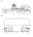
- Figure 1 is a plan view of a molding installation area where a molding installation device according to the present invention is applied, and there is provided an automobile door conveyance line 1.
- a pallet 2 is intermittently conveyed from right to left in the drawing along that conveyance line 1.
- a right side door W and a left side door W are alternately placed on each pallet 2.
- a roller conveyer 3 is arranged along the automobile door conveyance line 1.
- a bucket 4 for stocking a molding is provided on a side of the roller conveyer 3, and a predetermined molding M is set on the pallet 5 from the bucket 4.
- a pair of left and right moldings M are set on the pallet 5 so as to move from left to right on the roller conveyer 3 and the pallet 5 having been made vacant is caused to return to the original position (not illustrated in the drawing).
- two molding installation devices 6 are arranged along the roller conveyer 3.
- One molding installation device 6 is for the right side door W.
- the other molding installation device 6 is for the left side door W.
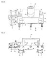
- Each of the molding installation devices 6 has molding installation jigs 10 and 100 provided on the tip section of two arms 7 and 8 which are driven independently. Since the molding installation jig 10 and the molding installation jig 100 are different only in the position of a finger for retaining the molding in the longitudinal direction, only the molding installation jigs 10 will be described in detail with reference to Figure 2 to Figure 5.
- Figure 2 is a plan view of the molding installation device
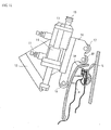
- Figure 3 is a plan view of a molding installation jig provided at a tip of an arm of the molding installation device.
- Figure 4 is a view seen from A direction of Figure 3
- Figure 5 is a view seen from B direction of Figure 3.
- the molding installation jig 10 has a dynamic sensor 12 between a jig body 11 and the arm 7.
- the dynamic sensor 12 is designed to detect force applied from the molding installation jig 10 to the molding M and recognize completion of work when the value thereof reaches a predetermined value.
- a finger 13 is supported on a side of the jig body 11 as a means for contacting and holding an end section of the molding M.
- the finger 13 is linked to a cylinder unit 14 and moves forward and backward by driving the cylinder unit 14.
- suction pads 15 communicating with a vacuum device are provided on a surface of the jig body 11 at equal intervals.
- the suction pads 15 protrude in the same direction as the forward and backward direction of the finger 13.
- brackets 16 having a C-shaped cross section are provided on a side surface of the jig body 11 which is perpendicular to the surface on which the suction pads 15 are provided.
- a first roller 17, a second roller 18, and a third roller 19 are rotatably supported in each of the brackets 16.
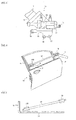
- Figure 6 is a view showing a first step among steps for installing a molding on a door panel
- Figure 7 is a view showing a state where an end of the molding is lowered
- Figure 8 is a view showing a state where a pressing finger of one molding installation jig is caused to retreat
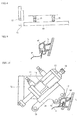
- Figure 9 is a sectional view showing a state where the molding is temporarily engaged
- Figure 10 is a sectional view showing a state where the molding is fit into the upper end of a door panel from the temporarily engaged state. Since a left side door undergoes the same operation, an explanation thereof will be omitted.
- the arms 7 and 8 are caused to come closer to each other.
- the fingers 13 of the left and right molding installation jigs 10 and 100 are brought into contact to the molding M from the longitudinal direction thereof as illustrated in Figure 6. Further the suction pads 15 suck the both end sections of the molding M and thereby hold the molding M between the left and right molding installation jigs 10 and 100.
- the molding M is substantially parallel to the upper end of an outer door panel P.
- the arm 8 of the molding installation device 6 is lowered as illustrated in Figure 7 to engage an end of the molding M with the outer door panel P. Further the arms 7 and 8 are moved to stick the end of the molding M on a garnish G.
- the finger 13 of the molding installation jig 10 is in contact with an end of the molding M. Therefore, in the other end near to the garnish G, the finger 13 is retreated in advance as illustrated in Figure 8. Incidentally, the end of the molding M is held by the suction pads 15 of the molding installation jig 100.
- the holding state with the finger 13 and the suction pads 15 is released; the arms 7 and 8 of the molding installation device 6 are operated to change the directions of the molding installation jigs 10 and 100, the first roller 17 is applied to the upper section of the molding M and the second roller 17 is applied to the side section of the molding M as illustrated in Figure 10, and the molding M is pressed downward and toward the inside of the automobile body so as to be fit into the upper end of the outer door panel P.
- the pressing direction of the molding M does not need to be precisely downward and sideward but can be in an oblique direction.
- Figure 11 is a diagram similar to Figure 10 showing another embodiment.
- a molding M which is large in the vertical dimension is fit.
- the first roller 17 is not used.
- the molding M is fit in a state where the second roller 18 is brought into contact with the upper section of the molding M and the third roller 19 is brought into contact with the side section of the molding M.
- the molding is provided at the upper end of the outer panel of the door.
- the present invention is also applicable to a case where the molding is provided at the upper end of an inner trim of the door.
Landscapes
- Engineering & Computer Science (AREA)
- Mechanical Engineering (AREA)
- Automobile Manufacture Line, Endless Track Vehicle, Trailer (AREA)
- Automatic Assembly (AREA)
Abstract
Description
- The present invention relates to an installation jig for automatically installing a molding (weather strip) on an upper end of a door panel of an automobile (outer panel or inner trim), an installation device (robot) provided with that installation jig at the tip of an arm and a method for installing the molding with the installation device.
- As disclosed in
Patent Literature 1, a molding (weather strip) is installed on upper ends of an outer panel and an inner trim configuring a door panel of an automobile; a lip section of the molding is brought into contact onto a window glass surface so that droplets and dusts will not enter the door panel in its inside at an occasion when the window glass is lowered. - As for the above described molding installation, automatic installation with a robot is carried out conventionally. That automatic installation is carried out by position control with a robot subjected to teaching of an installation position.
Patent Literature 1:Japanese Patent Application Publication No. 10-100681 - As described above, conventionally a molding is installed by automatic installing with a robot. However, installation is carried out only by controlling the positions of the robot. Therefore, unreasonable force is applied to the molding and the automobile body which can be occasionally damaged. In order to avoid this, a dedicated device for detecting abnormal operations is required beside the installation robot, giving rise to cost increase and deterioration in workability.
- In order to solve the above described problems, a molding installation jig according to the present invention comprises a suction pad for sucking a side surface of a molding; a finger brought into contact from the longitudinal direction of the molding; a roller for pressing the molding downward in order to fit the molding in a roller door panel and a roller for pressing the molding toward the inner side of an automobile body; and a dynamic sensor for detecting pressing force by those rollers, and a molding installation device is configured by providing the molding installation jig on respective tip sections of two arms which are driven independently.
- A dynamic sensor detects pressing force applied to the molding, and thereby occurrence of an abnormal operation can be determined instantly. In addition, deformation of the molding shape can be treated easily. Therefore, one molding installation jig can carry out fitting of moldings in different shapes.
- In addition, a roller for pressing a molding downward and a roller for pressing the molding toward the interior of an automobile body are used so as not to damage the molding. In addition, suction pads for sucking a side surface of a molding and a finger for pressing the molding in the longitudinal direction are used to facilitate installation and removal of a molding.
- In addition, molding installation jigs are provided at the tips of two arms which are independently driven. With this, the attitude of the molding can be changed arbitrarily, which make is possible to fit the molding into the upper end of a door panel easily without interfering with the other members.
- Also, according to a molding installation method by using the above described molding installation device, the dynamic sensor is used not to apply force of a predetermined value or more to a molding. Such a configuration enables a molding to smoothly fit into the upper end of a door panel.
- According to the present invention, in order to install a molding onto the upper end of a door panel, the molding can be smoothly installed without damaging the molding or an automobile body with unreasonable force. In addition, the molding installation jig itself is smaller and lighter than conventional ones. Therefore, a device (robot) in which the molding installation jig is incorporated becomes compact.
Moreover, in a case where the shape of a molding or a door panel is changed, the installation device can be used only by inputting information thereof. -
- Figure 1 is a plan view of a molding installation area where a molding installation device according to the present invention is applied;
- Figure 2 is a plan view of the molding installation device;
- Figure 3 is a plan view of a molding installation jig provided at a tip of an arm. of the molding installation device;
- Figure 4 is a view seen from A direction of Figure 3;
- Figure 5 is a view seen from B direction of Figure 3;
- Figure 6 is a view showing a first step among steps for installing a molding on a door panel;
- Figure 7 is a view showing a state where an end of the molding is lowered;
- Figure 8 is a view showing a state where a pressing finger of one molding installation jig is caused to retreat;
- Figure 9 is a sectional view showing a state where the molding is temporarily engaged;
- Figure 10 is a sectional view showing a state where the molding is fit into the upper end of a door panel from the temporarily engaged state; and
- Figure 11 is a diagram similar to Figure 10 showing another embodiment.
- Embodiments of the present invention will be described below with reference to the accompanying drawings. Figure 1 is a plan view of a molding installation area where a molding installation device according to the present invention is applied, and there is provided an automobile
door conveyance line 1. Apallet 2 is intermittently conveyed from right to left in the drawing along thatconveyance line 1. A right side door W and a left side door W are alternately placed on eachpallet 2. - A roller conveyer 3 is arranged along the automobile
door conveyance line 1. A bucket 4 for stocking a molding is provided on a side of the roller conveyer 3, and a predetermined molding M is set on the pallet 5 from the bucket 4. In this embodiment, a pair of left and right moldings M are set on the pallet 5 so as to move from left to right on the roller conveyer 3 and the pallet 5 having been made vacant is caused to return to the original position (not illustrated in the drawing). - In addition, two
molding installation devices 6 according to the present invention are arranged along the roller conveyer 3. Onemolding installation device 6 is for the right side door W. The othermolding installation device 6 is for the left side door W. - Each of the
molding installation devices 6 hasmolding installation jigs arms molding installation jig 10 and themolding installation jig 100 are different only in the position of a finger for retaining the molding in the longitudinal direction, only themolding installation jigs 10 will be described in detail with reference to Figure 2 to Figure 5. Figure 2 is a plan view of the molding installation device, Figure 3 is a plan view of a molding installation jig provided at a tip of an arm of the molding installation device. Figure 4 is a view seen from A direction of Figure 3, and Figure 5 is a view seen from B direction of Figure 3. - The
molding installation jig 10 has adynamic sensor 12 between ajig body 11 and thearm 7. Thedynamic sensor 12 is designed to detect force applied from themolding installation jig 10 to the molding M and recognize completion of work when the value thereof reaches a predetermined value. - A
finger 13 is supported on a side of thejig body 11 as a means for contacting and holding an end section of the molding M. Thefinger 13 is linked to acylinder unit 14 and moves forward and backward by driving thecylinder unit 14. - Also, three
suction pads 15 communicating with a vacuum device are provided on a surface of thejig body 11 at equal intervals. Thesuction pads 15 protrude in the same direction as the forward and backward direction of thefinger 13. - Further, a pair of
brackets 16 having a C-shaped cross section are provided on a side surface of thejig body 11 which is perpendicular to the surface on which thesuction pads 15 are provided. Afirst roller 17, asecond roller 18, and athird roller 19 are rotatably supported in each of thebrackets 16. - Next, with the
molding installation device 6 configured as described above, a procedure of installing a molding M on an outer panel of a right side door W will be described with reference to Figure 6 to Figure 10. Figure 6 is a view showing a first step among steps for installing a molding on a door panel, Figure 7 is a view showing a state where an end of the molding is lowered, Figure 8 is a view showing a state where a pressing finger of one molding installation jig is caused to retreat, Figure 9 is a sectional view showing a state where the molding is temporarily engaged, and Figure 10 is a sectional view showing a state where the molding is fit into the upper end of a door panel from the temporarily engaged state. Since a left side door undergoes the same operation, an explanation thereof will be omitted. - At first, the
arms fingers 13 of the left and rightmolding installation jigs suction pads 15 suck the both end sections of the molding M and thereby hold the molding M between the left and right molding installation jigs 10 and 100. In this instance, the molding M is substantially parallel to the upper end of an outer door panel P. - Subsequently, the
arm 8 of themolding installation device 6 is lowered as illustrated in Figure 7 to engage an end of the molding M with the outer door panel P. Further thearms finger 13 of themolding installation jig 10 is in contact with an end of the molding M. Therefore, in the other end near to the garnish G, thefinger 13 is retreated in advance as illustrated in Figure 8. Incidentally, the end of the molding M is held by thesuction pads 15 of themolding installation jig 100. - Subsequently, the
arm 7 on which themolding installation jig 10 is provided is lowered to temporarily engage the entire molding M with the outer door panel P. Figure 9 shows this state. That is, the upper end of the outer door panel P enters the molding M. A lip section L of the molding M is in contact with a window glass, and with its reaction force, the upper section of the molding M is inclined toward the outside of the automobile body. - From this state, the holding state with the
finger 13 and thesuction pads 15 is released; thearms molding installation device 6 are operated to change the directions of the molding installation jigs 10 and 100, thefirst roller 17 is applied to the upper section of the molding M and thesecond roller 17 is applied to the side section of the molding M as illustrated in Figure 10, and the molding M is pressed downward and toward the inside of the automobile body so as to be fit into the upper end of the outer door panel P.
Incidentally, the pressing direction of the molding M does not need to be precisely downward and sideward but can be in an oblique direction. - Force applied to the molding M at the time of being fit is detected with the dynamic sensor 1.2 all the time. When the applied force exceeds a predetermined value, the work is stopped. With this, it is possible to avoid a disadvantage that the molding M or the automobile body is damaged.
- Figure 11 is a diagram similar to Figure 10 showing another embodiment. In this embodiment, a molding M which is large in the vertical dimension is fit. In this case, the
first roller 17 is not used. The molding M is fit in a state where thesecond roller 18 is brought into contact with the upper section of the molding M and thethird roller 19 is brought into contact with the side section of the molding M. - In the drawings, the molding is provided at the upper end of the outer panel of the door. However, the present invention is also applicable to a case where the molding is provided at the upper end of an inner trim of the door.
Claims (2)
- A molding installation device comprising a molding installation jig on respective tip sections of two arms which are driven independently,
wherein the molding installation jig comprises a suction pad for sucking a side surface of a molding; a finger brought into contact from the longitudinal direction of the molding; a roller for pressing the molding downward in order to fit the molding in a roller door panel and a roller for pressing the molding toward the inner side of an automobile body; and a dynamic sensor for detecting pressing force by those rollers. - A molding installation method by using the molding installation device according to claim 1, wherein force of a predetermined value or more is not applied by using the dynamic sensor when the molding is fit.
Applications Claiming Priority (2)
| Application Number | Priority Date | Filing Date | Title |
|---|---|---|---|
| JP2004345174A JP4376173B2 (en) | 2004-11-30 | 2004-11-30 | Mall mounting method and apparatus |
| PCT/JP2005/021513 WO2006059521A1 (en) | 2004-11-30 | 2005-11-24 | Molding installation method and device |
Publications (3)
| Publication Number | Publication Date |
|---|---|
| EP1820719A1 true EP1820719A1 (en) | 2007-08-22 |
| EP1820719A4 EP1820719A4 (en) | 2008-04-16 |
| EP1820719B1 EP1820719B1 (en) | 2010-09-01 |
Family
ID=36564955
Family Applications (1)
| Application Number | Title | Priority Date | Filing Date |
|---|---|---|---|
| EP05809184A Expired - Fee Related EP1820719B1 (en) | 2004-11-30 | 2005-11-24 | Molding installation method and device |
Country Status (7)
| Country | Link |
|---|---|
| US (2) | US7748094B2 (en) |
| EP (1) | EP1820719B1 (en) |
| JP (1) | JP4376173B2 (en) |
| CN (1) | CN100486755C (en) |
| CA (1) | CA2591863C (en) |
| DE (1) | DE602005023337D1 (en) |
| WO (1) | WO2006059521A1 (en) |
Cited By (1)
| Publication number | Priority date | Publication date | Assignee | Title |
|---|---|---|---|---|
| CN102672664A (en) * | 2012-05-22 | 2012-09-19 | 奇瑞汽车股份有限公司 | Rubbing-preventing strip pressing-pasting tool |
Families Citing this family (16)
| Publication number | Priority date | Publication date | Assignee | Title |
|---|---|---|---|---|
| JP4376173B2 (en) * | 2004-11-30 | 2009-12-02 | 本田技研工業株式会社 | Mall mounting method and apparatus |
| US8322005B2 (en) * | 2008-10-23 | 2012-12-04 | Pow Specialty Equipment Inc. | Weather strip installation device |
| KR100934965B1 (en) * | 2009-07-17 | 2010-01-06 | 주식회사 신라정밀 | Apparatus for inserting seal in slewing bearing |
| FR2951393B1 (en) * | 2009-10-16 | 2011-11-11 | Peugeot Citroen Automobiles Sa | TOOL FOR INSTALLING A SEAL IN AN OPENING SHEET OF A VEHICLE |
| DE102010018298B4 (en) * | 2010-04-23 | 2013-05-29 | Grohmann Engineering Gmbh | retaining strip |
| JP5202660B2 (en) * | 2011-01-27 | 2013-06-05 | 東亜工業株式会社 | Automatic sticking device for foam sealing material |
| US9120369B2 (en) * | 2011-12-19 | 2015-09-01 | Fca Us Llc | Glass run installation tool |
| DE102013114775A1 (en) * | 2013-12-23 | 2015-06-25 | Cqlt Saargummi Technologies S.À.R.L. | Method for forming seals on vehicle bodies |
| CN104029153B (en) * | 2014-07-09 | 2015-10-07 | 南京航空航天大学 | For the Omni-mobile frock of revolving shell Product Assembly |
| US9902449B2 (en) | 2015-04-20 | 2018-02-27 | Honda Motor Co., Ltd. | Door garnish mounting device |
| US10279563B2 (en) | 2015-09-29 | 2019-05-07 | Honda Motor Co., Ltd. | Sash garnish press system and method |
| CN106181849A (en) * | 2016-08-26 | 2016-12-07 | 天津住宅集团建材科技有限公司 | A kind of manual mounts of inward-opening door/window sealing joint strip |
| CA3109910A1 (en) * | 2018-08-17 | 2020-02-20 | Magna Exteriors Inc. | Mechanical variable gap crimp tool |
| DE102019207127A1 (en) * | 2019-05-16 | 2020-11-19 | Thyssenkrupp Ag | Application unit with pressure force measurement |
| US11110554B2 (en) | 2019-07-19 | 2021-09-07 | Honda Motor Co., Ltd. | Garnish installing apparatus and methods of making and using the same |
| US11623310B2 (en) | 2019-08-28 | 2023-04-11 | Honda Motor Co., Ltd. | Installation apparatus for mounting a garnish onto a vehicle structure and methods of making and using the same |
Family Cites Families (21)
| Publication number | Priority date | Publication date | Assignee | Title |
|---|---|---|---|---|
| US4183511A (en) * | 1978-08-30 | 1980-01-15 | Marek Richard G | Work holder for adjustably supporting a workpiece |
| US4715110A (en) * | 1986-07-18 | 1987-12-29 | General Motors Corporation | Apparatus of a robot for installing weather stripping in a door or like opening |
| US4760636A (en) | 1986-07-18 | 1988-08-02 | General Motors Corporation | Apparatus of a robot for installing weather stripping in a door or like opening |
| US5067225A (en) * | 1988-12-19 | 1991-11-26 | General Motors Corporation | Method of a robot for installing weather stripping in a door or like opening |
| US4961257A (en) * | 1989-02-02 | 1990-10-09 | Mazda Motor Corporation | Door assembling apparatus for use in automobile assembly |
| FI900752A7 (en) * | 1989-03-09 | 1990-09-10 | Ferco Int Usine De Ferrures De Batiment | Machine for automatically installing flexible seals, especially external seals, in window gaps |
| GB8927677D0 (en) * | 1989-12-07 | 1990-02-07 | Draftex Ind Ltd | Apparatus for fitting flexible strips |
| EP0476983B1 (en) | 1990-09-21 | 2000-03-15 | Merck & Co. Inc. | Vascular endothelial cell growth factor II |
| US5301411A (en) * | 1991-06-28 | 1994-04-12 | Mazda Motor Corporation | Elongated work assembling method |
| JPH05200638A (en) * | 1992-01-22 | 1993-08-10 | Mazda Motor Corp | Assembling method and device for small parts |
| JPH08155843A (en) | 1994-11-30 | 1996-06-18 | Nishikawa Rubber Co Ltd | Weather strip mounting jig |
| JPH08174353A (en) | 1994-12-26 | 1996-07-09 | Mitsubishi Motors Corp | Weather-strip mounting device |
| US5875670A (en) * | 1996-07-31 | 1999-03-02 | The Standard Products Company | Tool for roll crimping a flange cover |
| JP3228147B2 (en) | 1996-09-25 | 2001-11-12 | 三菱自動車工業株式会社 | Door structure |
| US6886231B2 (en) * | 1999-06-25 | 2005-05-03 | Burke E. Porter Machinery Company | Robotic apparatus and method for mounting a valve stem on a wheel rim |
| GB2366317B (en) * | 2000-04-04 | 2003-09-17 | Honda Motor Co Ltd | Tool and process for press-fitting weather strip |
| US7039995B2 (en) * | 2002-07-08 | 2006-05-09 | Thompson Bobby D | Windshield removal and replacement apparatus |
| US7310865B2 (en) * | 2004-02-17 | 2007-12-25 | General Motors Corporation | Gap setting tool and method of operating same |
| WO2006054764A1 (en) * | 2004-11-22 | 2006-05-26 | Honda Motor Co., Ltd. | Method for installing run channel for automobile, device for installing run channel for automobile, and soft member installation device |
| JP4376173B2 (en) * | 2004-11-30 | 2009-12-02 | 本田技研工業株式会社 | Mall mounting method and apparatus |
| US7552283B2 (en) * | 2006-01-20 | 2009-06-23 | Qualcomm Incorporated | Efficient memory hierarchy management |
-
2004
- 2004-11-30 JP JP2004345174A patent/JP4376173B2/en not_active Expired - Fee Related
-
2005
- 2005-11-24 CA CA2591863A patent/CA2591863C/en not_active Expired - Fee Related
- 2005-11-24 WO PCT/JP2005/021513 patent/WO2006059521A1/en not_active Ceased
- 2005-11-24 CN CNB2005800410077A patent/CN100486755C/en not_active Expired - Fee Related
- 2005-11-24 DE DE602005023337T patent/DE602005023337D1/en not_active Expired - Lifetime
- 2005-11-24 US US11/720,446 patent/US7748094B2/en not_active Expired - Fee Related
- 2005-11-24 EP EP05809184A patent/EP1820719B1/en not_active Expired - Fee Related
-
2010
- 2010-06-14 US US12/814,819 patent/US8336184B2/en not_active Expired - Fee Related
Cited By (2)
| Publication number | Priority date | Publication date | Assignee | Title |
|---|---|---|---|---|
| CN102672664A (en) * | 2012-05-22 | 2012-09-19 | 奇瑞汽车股份有限公司 | Rubbing-preventing strip pressing-pasting tool |
| CN102672664B (en) * | 2012-05-22 | 2014-10-01 | 奇瑞汽车股份有限公司 | Rubbing-preventing strip pressing-pasting tool |
Also Published As
| Publication number | Publication date |
|---|---|
| JP4376173B2 (en) | 2009-12-02 |
| CA2591863C (en) | 2012-04-03 |
| CA2591863A1 (en) | 2006-06-08 |
| CN101068708A (en) | 2007-11-07 |
| JP2006151207A (en) | 2006-06-15 |
| US7748094B2 (en) | 2010-07-06 |
| US8336184B2 (en) | 2012-12-25 |
| EP1820719A4 (en) | 2008-04-16 |
| EP1820719B1 (en) | 2010-09-01 |
| US20080047119A1 (en) | 2008-02-28 |
| WO2006059521A1 (en) | 2006-06-08 |
| CN100486755C (en) | 2009-05-13 |
| DE602005023337D1 (en) | 2010-10-14 |
| US20100293773A1 (en) | 2010-11-25 |
Similar Documents
| Publication | Publication Date | Title |
|---|---|---|
| US8336184B2 (en) | Molding installation method and device | |
| EP1958714B1 (en) | Hemming method and hemming device | |
| CN101772402A (en) | Workpiece conveying device and workpiece setting method | |
| CN112071781B (en) | Debonding device and method | |
| JP2019041051A (en) | Adhesive tape peeling method and adhesive tape peeling device | |
| KR100513401B1 (en) | The robot of Semiconductor wafer transportation and alignment method using the same | |
| JP4950760B2 (en) | Conveying device, cleaning device, and method for manufacturing liquid crystal display device | |
| US6466837B1 (en) | Parts installation method and parts mounting method and mounter | |
| CN114380047A (en) | Robot clamping device and clamping method thereof, carrier plate magazine and composite robot | |
| JP7598520B2 (en) | Burr removal device | |
| JP3630938B2 (en) | Thin sticker automatic sticking method and apparatus | |
| JP2005297138A (en) | Body side panel transfer device and body side panel positioning method | |
| KR100201316B1 (en) | Automatic label attachment device for tire | |
| KR100754764B1 (en) | Vacuum adsorption system operated by robot arm | |
| JP4690875B2 (en) | Hemming processing method and processing apparatus | |
| JP2009095844A (en) | Press machine | |
| JP2678469B2 (en) | Dam rubber mount stripping device | |
| JP3314968B2 (en) | Plate member positioning device | |
| CN111689282B (en) | Leveling unit of conveying device and electronic component operation equipment applying leveling unit | |
| JPH10181903A (en) | Flat plate unloading device | |
| JPH10236644A (en) | Plate-like workpiece supply device | |
| JPH0440829Y2 (en) | ||
| KR20230152976A (en) | Appartus for removing core of weather strip | |
| JP2007152394A (en) | Hemming processing method and processing apparatus | |
| WO2007029704A1 (en) | Process for manufacturing door trim assembly and manufacturing line therefor |
Legal Events
| Date | Code | Title | Description |
|---|---|---|---|
| PUAI | Public reference made under article 153(3) epc to a published international application that has entered the european phase |
Free format text: ORIGINAL CODE: 0009012 |
|
| 17P | Request for examination filed |
Effective date: 20070530 |
|
| AK | Designated contracting states |
Kind code of ref document: A1 Designated state(s): DE GB |
|
| DAX | Request for extension of the european patent (deleted) | ||
| RBV | Designated contracting states (corrected) |
Designated state(s): DE GB |
|
| A4 | Supplementary search report drawn up and despatched |
Effective date: 20080319 |
|
| 17Q | First examination report despatched |
Effective date: 20080602 |
|
| GRAP | Despatch of communication of intention to grant a patent |
Free format text: ORIGINAL CODE: EPIDOSNIGR1 |
|
| GRAS | Grant fee paid |
Free format text: ORIGINAL CODE: EPIDOSNIGR3 |
|
| GRAA | (expected) grant |
Free format text: ORIGINAL CODE: 0009210 |
|
| AK | Designated contracting states |
Kind code of ref document: B1 Designated state(s): DE GB |
|
| REG | Reference to a national code |
Ref country code: GB Ref legal event code: FG4D |
|
| REF | Corresponds to: |
Ref document number: 602005023337 Country of ref document: DE Date of ref document: 20101014 Kind code of ref document: P |
|
| PGFP | Annual fee paid to national office [announced via postgrant information from national office to epo] |
Ref country code: DE Payment date: 20101117 Year of fee payment: 6 |
|
| PGFP | Annual fee paid to national office [announced via postgrant information from national office to epo] |
Ref country code: GB Payment date: 20101124 Year of fee payment: 6 |
|
| PLBE | No opposition filed within time limit |
Free format text: ORIGINAL CODE: 0009261 |
|
| STAA | Information on the status of an ep patent application or granted ep patent |
Free format text: STATUS: NO OPPOSITION FILED WITHIN TIME LIMIT |
|
| 26N | No opposition filed |
Effective date: 20110606 |
|
| REG | Reference to a national code |
Ref country code: DE Ref legal event code: R097 Ref document number: 602005023337 Country of ref document: DE Effective date: 20110606 |
|
| GBPC | Gb: european patent ceased through non-payment of renewal fee |
Effective date: 20121124 |
|
| REG | Reference to a national code |
Ref country code: DE Ref legal event code: R119 Ref document number: 602005023337 Country of ref document: DE Effective date: 20130601 |
|
| PG25 | Lapsed in a contracting state [announced via postgrant information from national office to epo] |
Ref country code: DE Free format text: LAPSE BECAUSE OF NON-PAYMENT OF DUE FEES Effective date: 20130601 |
|
| PG25 | Lapsed in a contracting state [announced via postgrant information from national office to epo] |
Ref country code: GB Free format text: LAPSE BECAUSE OF NON-PAYMENT OF DUE FEES Effective date: 20121124 |