EP1820690A1 - Automobile seat system - Google Patents
Automobile seat system Download PDFInfo
- Publication number
- EP1820690A1 EP1820690A1 EP06003479A EP06003479A EP1820690A1 EP 1820690 A1 EP1820690 A1 EP 1820690A1 EP 06003479 A EP06003479 A EP 06003479A EP 06003479 A EP06003479 A EP 06003479A EP 1820690 A1 EP1820690 A1 EP 1820690A1
- Authority
- EP
- European Patent Office
- Prior art keywords
- seat
- surface region
- user
- ventilation
- arrangement
- Prior art date
- Legal status (The legal status is an assumption and is not a legal conclusion. Google has not performed a legal analysis and makes no representation as to the accuracy of the status listed.)
- Granted
Links
Images


Classifications
-
- B—PERFORMING OPERATIONS; TRANSPORTING
- B60—VEHICLES IN GENERAL
- B60N—SEATS SPECIALLY ADAPTED FOR VEHICLES; VEHICLE PASSENGER ACCOMMODATION NOT OTHERWISE PROVIDED FOR
- B60N2/00—Seats specially adapted for vehicles; Arrangement or mounting of seats in vehicles
- B60N2/56—Heating or ventilating devices
- B60N2/5678—Heating or ventilating devices characterised by electrical systems
- B60N2/5685—Resistance
-
- B—PERFORMING OPERATIONS; TRANSPORTING
- B60—VEHICLES IN GENERAL
- B60N—SEATS SPECIALLY ADAPTED FOR VEHICLES; VEHICLE PASSENGER ACCOMMODATION NOT OTHERWISE PROVIDED FOR
- B60N2/00—Seats specially adapted for vehicles; Arrangement or mounting of seats in vehicles
- B60N2/56—Heating or ventilating devices
- B60N2/5607—Heating or ventilating devices characterised by convection
- B60N2/5621—Heating or ventilating devices characterised by convection by air
- B60N2/5635—Heating or ventilating devices characterised by convection by air coming from the passenger compartment
-
- B—PERFORMING OPERATIONS; TRANSPORTING
- B60—VEHICLES IN GENERAL
- B60N—SEATS SPECIALLY ADAPTED FOR VEHICLES; VEHICLE PASSENGER ACCOMMODATION NOT OTHERWISE PROVIDED FOR
- B60N2/00—Seats specially adapted for vehicles; Arrangement or mounting of seats in vehicles
- B60N2/56—Heating or ventilating devices
- B60N2/5607—Heating or ventilating devices characterised by convection
- B60N2/5621—Heating or ventilating devices characterised by convection by air
- B60N2/565—Heating or ventilating devices characterised by convection by air sucked from the seat surface
-
- B—PERFORMING OPERATIONS; TRANSPORTING
- B60—VEHICLES IN GENERAL
- B60N—SEATS SPECIALLY ADAPTED FOR VEHICLES; VEHICLE PASSENGER ACCOMMODATION NOT OTHERWISE PROVIDED FOR
- B60N2/00—Seats specially adapted for vehicles; Arrangement or mounting of seats in vehicles
- B60N2/56—Heating or ventilating devices
- B60N2/5607—Heating or ventilating devices characterised by convection
- B60N2/5621—Heating or ventilating devices characterised by convection by air
- B60N2/5657—Heating or ventilating devices characterised by convection by air blown towards the seat surface
Definitions
- the present invention relates to automobile seat systems, for example to automobile seat systems including corresponding seats which are capable in operation of providing greater user comfort. Moreover, the present invention also relates to methods of controlling such seat systems for providing enhanced user comfort. Furthermore, the present invention concerns automobile climate control systems including such seat systems.
- climate control within automobiles has become increasingly complex from earlier open-loop-control user adjustment of fan speed and blending of hot and cold air streams supplied to automobile compartments.
- Modern contemporary climate control within automobiles often employs air conditioning apparatus for ensuring a substantially constant user-selectable temperature within automobile passenger compartments; such air conditioning is implemented to function according to closed-loop feedback control aiming to achieve a reference set temperature within passenger compartments. In practice, such closed-loop feedback control is operable only approximately to achieve the reference set temperature.
- the passenger seat described includes a carrier structure for a seat backrest provided with a cushion block.
- the cushion block is covered on its front side facing an associated seated passenger with a cushioned layer which is operable to allow passage of air therethrough.
- a rear side of the cushion block remote from the seated passenger is implemented to include an impervious barrier layer so as to be substantially impervious to airflow therethrough.
- the impervious barrier layer comprises therein one or more openings for accommodating one or more fans. The fans are operable to transport air through the cushion block. The air flow is guided in a longitudinal direction of the seat backrest by guide elements embedded in the cushion block.
- the present invention is directed at addressing a technical problem of increasing passenger and driver comfort in automobiles.
- An object of the present invention is to improve passenger and driver comfort in automobiles and similar such road vehicles.
- an automobile seat system including an automobile seat having a surface region contactable in use to a user of the seat, the seat system being configured to provide environmental control substantially at the surface region of the seat for providing enhanced user comfort, the seat system comprising:
- the invention is of advantage in that use of ventilated automobile seats with local feedback control is susceptible to improving passenger and driver comfort in automobiles.
- the seat system further includes a heating arrangement for heating substantially said surface region, wherein said feedback loop control is operable to control at least one of said one or more physical parameters by selectively controlling said heating arrangement.
- a heating arrangement for heating substantially said surface region, wherein said feedback loop control is operable to control at least one of said one or more physical parameters by selectively controlling said heating arrangement.
- the ventilation arrangement is operable to suck air from the surface region through the seat.
- Suction of air into the seat is preferable to blowing air via an inner area of the seat to the surface region on account of more rapid cooling being possible and the feedback control loop being provided with a lower-order system to control, thereby potentially enabling more accurate control to be achieved.
- the sensor arrangement is substantially spatially located within the seat substantially adjacent to the surface region. Such close location is susceptible to providing a more rapid response for ensuring user comfort as well as providing the feedback loop control with a lower order system to control.
- the ventilation arrangement comprises a plurality of ventilation channels distributed within the seat, the plurality of ventilation channels being disposed so as to couple the surface region to one or more ventilation fans.
- the sensor arrangement includes one or more temperature sensors for measuring one or more temperatures of the surface region.
- Such one or more temperature sensors enable the feedback loop control to regulate the surface region selectively in response to temperature measurement signals derived from the one or more temperature sensors, thereby providing enhanced user comfort.
- the sensor arrangement optionally also includes sensors spatially remote from the seat, for example solar sensors for measuring an energy density of solar radiation and hence potential warming of the seat caused by such solar radiation.
- the sensor arrangement further includes at least one of: one or more humidity sensors for sensing humidity of the surface region, one or more pressure sensors for detecting a spatial extent of the user in contact with the surface region, and one or more sensors for sensing solar radiation.
- additional sensors are of benefit in that they enable other parameters affecting user comfort to be assessed so that ventilation or cooling applied to the surface region in operation can be more finely and appropriately adjusted to ensure enhanced user comfort.
- the feedback loop control is operable to maintain the surface region at a temperature regulated in respect of a desired degree of comfort selected by the user.
- the desired degree of comfort optionally defines a reference temperature to which the temperature of the surface region is to be regulated. Temperature has beneficially been found to be a best indicator of user comfort for the seat system including feedback control.
- the surface region is configured to be in airflow communication with the ventilation arrangement, and with the sensor arrangement via a plurality of ventilation holes, the ventilation holes being disposed on the surface region in a spatial arrangement for optimally ventilating the user when seated in the seat.
- a nonuniform distribution of the perforation holes in response to anticipated shape of various parts of the user in proximity of the surface region of the seat enables a more effective control of temperature across the surface region to be achieved, thereby potentially increasing user comfort.
- ventilation channels provided in the seat can have mutually different diameters for optimizing specific regions of the surface which are to be controlled in temperature.
- the surface region is configured to be in airflow communication with the ventilation arrangement, and with the sensor arrangement via a plurality of ventilation holes, the ventilation holes having mutually different diameters for optimally ventilating the user when seated in the seat.
- the feedback loop control is operable to being activated remotely for pre-cooling or pre-heating the surface region prior to the user assuming contact with the surface region.
- pre-cooling is of benefit when the automobile has been parked in bright sunlight for an extensive period so that the surface region of the seat attains an uncomfortably high temperature, for example approaching 80 °C or even 100 °C.
- Pre-cooling the seat is capable of ensuring that the user does not become scorched or experiences discomfort when first being seated in the seat after such a period of parking.
- pre-cooling is invoked in response to an intensity of solar radiation sensed by the sensor arrangement.
- an automobile seat for an automobile seat system according to the first aspect of the invention.
- a climate control system for an automobile including a passenger compartment including at least one seat system according to the first aspect of the invention, the control system including a first control feedback loop for executing climate control within the compartment, and a second feedback control loop for executing climate control of one or more surface regions of one or more seats of the one or more seat systems, the one or more surface regions being susceptible to being in contact with the user.
- an automobile including a climate control system according to the third aspect of the invention.
- the method includes a step of configuring the feedback loop control to render it operable to being activated remotely for pre-cooling or pre-heating the surface region prior to the user assuming contact with the surface region.
- the automobile 10 comprises an automobile structure 20 within which a passenger and driver compartment denoted by 30 is included.
- the compartment 30 includes front seats 40 and one or more rear seats 50; for example, the one or more rear seats 50 can optionally be implemented as a single broad sofa-type seat.
- the automobile 10 is provided with a climate control unit (CCU) 60 including devices such as air-conditioning units, electrical air heaters, air filters and humidifiers; the climate control unit 60 is coupled in communication with the compartment 30.
- CCU climate control unit
- the automobile 10 travels at a velocity V auto in a forward direction denoted by an arrow 70 which causes air flow over and under the automobile 10, such air flow being denoted by 80; the air flow 80 is susceptible to causing heat loss or heat gain to the automobile 10 depending upon a difference between a temperature T ext external to the automobile 10 and a measured internal temperature T int inside the passenger and driver compartment 30.
- the automobile 10 is exposed to solar radiation 100 from the sun 90; the solar radiation 100 is capable to delivering heat energy P sol to the automobile 10 as will be elucidated in more detail later.
- a driver or passenger of the automobile 10 is able to set a desired target internal temperature T ref which the climate control unit (CCU) 60 is operable to try to establish within the compartment 30; namely, the control unit 60 is operable by feedback to try to adjust the measured internal temperature T int by input or extraction of heat energy from the compartment 30 so as to match the target temperature T ref .
- the passenger or driver is further provided with an option of selecting seat heating or seat ventilation.
- the seat ventilation is optionally user-selectable to be at a plurality of different ventilation fan speeds.
- climate control unit 60 is susceptible to operating in a feedback mode to match the measured internal temperature T int with the target temperature T ref , adjustment of seat heating and seat ventilation is user-selectable in essentially an open-loop control manner wherein the passenger or driver himself or herself provides feedback adjustment in response to their degree of comfort or discomfort as appropriate.
- the seat 40 is generally indicated to include a seat portion 200 and a backrest portion 210.
- the seat portion 200 is substantially horizontal as illustrated, whereas the backrest portion 210 is near vertical, for example nominally at an angle ⁇ in a range of 0° to 30° relative to a vertical direction.
- the angle ⁇ is optionally user-adjustable for adjusting for optimal backrest comfort.
- the seat portion 200 and/or the backrest portion 210 include electrically-driven ventilation fans 230, 240 respectively.
- the seat portion 200 and the backrest portion 210 include therein air channels for directing airflow generated by the fans 230, 240 in operation through the portions 200, 210 as denoted by arrows 250, 260 to diffuse finally at surfaces of the portions 200, 210 directed towards a body of a passenger or driver (not shown) seated in the seat 40.
- Electrical excitation to the fans 230, 240 is controllable from a control unit 300 provided with electrical power 310 from a battery, fuel cell or generator (not shown) of the automobile 10; the control unit 300 is optionally included as an integral part of the aforesaid climate control unit 60.
- the control unit 300 comprises a user-depressible switch 320 for controlling a degree of electrical excitation applied to the fans 230, 240 in operation.
- the switch 320 is preferable positioned on a central control column of the automobile 10. Repeated depression of the switch 320 preferable controls excitation to the fans 230, 240 in a cyclical manner as indicated by 350; the switch 320 is operable to control four different electrical excitations applied to the fans 230, 240 as elucidated in Table 1.
- the cyclical manner 350 is invoked in a manner illustrated in Figure 2.
- the fans 230, 240 are energized at a fan excitation state 0
- impellers of the fans 230, 240 are not rotating thereby resulting in insignificant airflow through the portions 200, 210.
- the control unit 300 is operable to switch to a fan excitation state 3, wherein the impellers of the fans 230, 240 are excited to rotate at their higher rate to cause a higher rate of airflow through the portions 200, 210, thereby providing the passenger or driver seated upon the seat 40 with a maximum degree of cooling.
- the control unit 300 When the switch 320 is then depressed a further time by the user, the control unit 300 is operable to switch to a fan excitation state 2, wherein the impellers of the fans 230, 240 are excited to rotate at their intermediate rate to cause a medium rate of airflow through the portions 200, 210, thereby providing an intermediate degree of cooling.
- the control unit 300 is operable to switch to a fan excitation state 1, wherein the impellers of the fans 230, 240 are excited to rotate at their lower rate to cause a lower rate of airflow through the portions 200, 210, thereby providing a lower degree of cooling.
- a yet further user depression of the switch 320 results in the control unit 300 switching to the aforementioned fan excitation state 0. Further user depression of the switch 320 causes the cyclical manner 350 to be repeated as described above.
- the seats 40, 50 are also provided with in-built heating features.
- the control unit 300 is provided with a further user-depressible switch 330 which is operable to control electrical excitation applied to resistive heating elements 400, 410 included in the portions 200, 210 of the seat 40 respectively. Heating of the seats 40, 50 can be selectively invoked in the automobile 10 by user-depression of the switch 330 in an ON-OFF manner.
- a reason for surprising results as presented in Figure 4 is the complexity of the climate in practice within the compartment 30. Rather than being an isothermal environment, the compartment 30 has complex temperature and humidity gradients in response to a number of passengers and driver included in the compartment 30 and external parameters such as ambient incident sunlight and airflow over external surfaces of the automobile 10.
- Such complexity of the climate within the compartment 30 is represented in Figure 5.
- a temperature difference between the external temperature T ext and the internal compartment temperature T int determines a rate of heat flow into or out of the compartment 30.
- the solar radiation 100 is susceptible to providing a heating power input P sol to the compartment 30 as a complex function of an angle of incidence of the solar radiation 100 relative to angle of external surfaces of the automobile 10 and optical transmittivity of surfaces of the automobile 10; for example, window regions of the automobile 10 are operable to transmit potentially more of the solar radiation 100 into the compartment 30 in comparison to metal panels of bodywork of the automobile 10, although dependent on color of surface finish of such metal panels.
- heat energy loss or gain from the compartment 30 is also dependent on the velocity of travel of the automobile V auto , for example by way of wind chill factor.
- external humidity H ext can affect internal humidity H int of the compartment 30 which in turn has a physiological affect on perceived optimal user comfort.
- FIG. 6 there is shown a climate control system pursuant to the present invention; the system includes a feed-back controlled ventilated automobile seat as a component part thereof; beneficially, the present invention is applied to a seat as depicted in Figures 8 and 9, although the seats 40, 50 are also capable of being adapted to function pursuant to the present invention.
- the compartment 30 is provided with a temperature sensor arrangement 710, either measuring at a single point within the compartment 30 or at several spatially different points within the compartment 30.
- the measured internal temperature of the compartment, T int is conveyed to an error generator 700 forming a part of the climate control unit 60; an error temperature difference from the error generator 700 is used to control cooling or heating provided by the climate control unit 60.
- the aforementioned local environment 600 for purposes of implementing the present invention is assumed to be substantially a surface of the seat 40, 50 on account of skin temperature-sensing nerves of the user being a best indication of optimal user comfort.
- a region of the surface of the seat 40, 50 defining the environment 600 is provided with a sensor arrangement denoted by 760; the sensor arrangement 760 optionally comprises a plurality of distributed temperature sensors. More optionally, the sensor arrangement 760 can be complemented by other types of sensors, for example humidity sensors for measuring local humidity variations occurring in operation within the environment 600. Also, optionally the sensor arrangement 760 includes input components and/or sensors located at positions other than in a vicinity of the automobile seat 40, 50.
- Examples of such input components and/or sensors that are optionally included in the sensor arrangement 760 include: a cooling fluid temperature sensor operable to sense a temperature of a cooling fluid, an arrangement for providing an indication of an air-conditioning fan control voltage, a temporal sensor or clock for measuring a time elapsed since start/restart of the automobile 10, a temporal sensor or clock for measuring a time elapsed since the automobile 10 has been stationary or in a parked state, a monitor for sensing climate control temperature setting.
- the sensor arrangement 760 includes one or more sensors and/or input components for sensing or monitoring the following parameters for use in controlling the seat 40, 50:
- Measurement signals provided in operation from the sensor arrangement 760 are coupled to an error generator 750 which has a user-adjustable comfort parameter K omf as an input reference.
- the error generator 750 is operable to generate error signals for controlling excitation to the fans 230, 240 and also to the heating elements 400, 410.
- the error generator 750 is included as a part of the climate control unit 60.
- an outer feedback control loop for controlling comfort of the compartment 30
- an inner feedback control loop for controlling comfort of the local environment 600.
- the inner control loop is operable to try to match a temperature of the seat 40, 50 T seat to a temperature determined by or derived from the comfort parameter K omf .
- the inner control loop can adjust the temperature, optionally also the humidity, of the local environment 600 by selectively using one or more of the fans 230, 240 for cooling the environment 600, or one or more of the heaters 400, 410 for heating the environment 600.
- the comfort parameter K omf can be selected by way of the switch 320 as elucidated in the foregoing, however with a difference that the various states 0 to 3 of the switch 320 no longer simply control a degree of electrical excitation applied to the fans 230, 240 as in known contemporary climate control systems, but rather is used by the user to select a desired degree of comfort.
- curves 900, 910, 920 correspond to comfort states 1, 2 and 3 respectively; the comfort state 2 is designed to correspond to optimal comfort for a median of population, whereas the comfort state 1 is designed to be susceptible to nominally employing substantially in a range of 3 to 20% of ventilation capacity of the fans 230, 240, and whereas the comfort state 3 is designed to be susceptible to nominally employing most of the ventilation capacity of the fans 230, 240.
- the seats 40, 50 are optionally and beneficially modified in a manner as indicated by 1000 in Figure 8.
- the seat 1000 includes the seat portion 200 and the backrest portion 210.
- the one or more ventilation fans 230 of the seat portion 200 are configured to suck air from the seat portion 200, namely to generate in operation a suction airflow 1040 as illustrated.
- the one or more ventilation fans 240 of the backrest portion 210 are configured to suck air from the backrest portion 210, namely also to generate in operation a suction airflow 1030 as illustrated.
- suction airflows 1030, 1040 Use of the suction airflows 1030, 1040 is of benefit in that exterior surfaces of the seat portions 200, 210 can be more rapidly cooled in comparison to using the one or more fans 230, 240 to blow air into the seat; such rapid cooling is of considerable benefit when the seat portions 200, 210 have been exposed to ambient solar radiation when the automobile 10 has been parked without climate control in operation; solar radiation is known to approach an energy density of 1 kW/m 2 for sun inclinations substantially normal to the Earth's surface and can potentially cause the exterior surface of the seat 1000 to attain a temperature approaching 80 °C, even potentially as high as 100 °C, when ventilation is not applied to the seat 1000.
- the seat 1000 pursuant to the present invention also includes the aforementioned heating elements 400, 410 as illustrated.
- the seat 1000 further includes sensor arrangements 1010, 1020 in the seat portions 200, 210 respectively as illustrated.
- the sensor arrangements 1010, 1020 each include one or more spatially distributed temperature sensors for sensing substantially surface temperatures presented to the user when seated in the seat 1000 and in contact with its outer surfaces; optionally, the sensor arrangements 1010, 1020 also include other types of sensors such as humidity sensors and/or pressure sensors to sense a region of the seat 1000 whereat the user is seated, for example to gauge a spatial extent of the user seated on the seat 1000 and spatially adjust application of power to the heating elements 400, 410 accordingly.
- the switch 320 is, pursuant to the present invention, used to select the comfort state K omf in a cyclical manner akin to 350.
- the inner control loop is preferably provided with a function that an approach of the user to the automobile 10, for example the user 10 unlocking the automobile 10 from a distance on per se known manner, for instance using an infrared (IR) data link from a user key to the automobile 10, is operable to invoking ventilation cooling to the seat 1000 so that the outer surface of the seat 1000 when exposed to strong sunlight is cooled by a time that the user enters the compartment 30 to sit upon the seat 1000, thereby avoiding the user having an uncomfortable feeling of skin bums or scorching.
- IR infrared
- a cross-section through the seat portion 200 of the seat 1000 is indicated generally by 1500.
- a cross-sectional profile through the backrest portion 210 of the seat 1000 is substantially similar.
- the cross-section 1500 comprises an upper surface layer 1520 implemented in perforated upholstery material, such as perforated leather, namely including an array of perforation holes 1510 therein susceptible to enabling airflow through the upper layer 1520; the perforation holes 1510 are also referred to as being ventilation holes and can optionally be produced by methods other than perforating the upper surface layer 1520.
- the perforation holes 1510 are preferably differentially spatially distributed in density to those regions of the seat portion 200 and the backrest portion 210 where most ventilation is required for providing enhanced user comfort.
- the perforation holes 1510 are preferentially distributed to an upper surface region of the backrest portion 210 and to a peripheral surface region of the seat portion 200, so that the lower surface region of the backrest portion 210 and the central region of the seat portion 200 are preferably provided with a relatively lower concentration of the perforation holes 1510 in comparison to peripheral regions of the seat portion 200, 210; such a disposition of the holes 1510 is susceptible to ensuring that ventilation provided from the one or more fans 230, 240 is optimally utilized for ensuring user comfort.
- the perforation holes 1510 can be implemented with diameters which spatially vary across the surfaces of the seat and backrest portions 200, 210.
- Beneath the upper layer 1520 is provided a backing layer 1530 which is permeable to airflow and also mechanically operable to spread concentrations of load forces experienced by the upper layer which could potentially damage a heating element layer 1540 included below the backing layer 1530.
- the heating element layer 1540 includes heating devices denoted by 1550 for implementing the heating elements 400, 410; the heating devices 1550 are, for example, implemented as a thin-film metallic heating film or by a mesh of heating wires.
- an indication of heat output P pers of the user and/or user humidity H pers are also sensed at the sensor arrangement layer 1560, thereby effectively including the user's skin within the local environment 600.
- Such a juxtaposition of layers in combination with the one or more fans 230, 240 providing a suction airflow through the portions 200, 210 is a contributing factor to the present invention being susceptible to providing enhanced user comfort in comparison to known contemporary ventilate automobile seats.
- a spacing layer 1580 including periodically felt inserts 1590 and perpendicular ventilation channels 1610 therein as illustrated in Figure 9.
- a ventilation layer 1620 comprising a labyrinth of ventilation channels 1630 orientated substantially parallel to the upper surface layer 1520 and operable to couple airflow from the perpendicular ventilation channels 1610 to the one or more fans 230, 240 as appropriate.
- Disposing the channels 1610, 1630 as far as possible from the layers 1540, 1560 and hence the local environment 600 is susceptible to improving thermal performance of the seat 1000 and hence rapidity and accuracy of performance of the aforesaid inner control loop.
- the ventilation channels 1610, 1630 are of mutually different diameter for providing a preferential distribution of ventilation in the seat 1000 for enhancing user comfort.
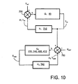
- FIG. 10 a feedback representation of a climate control system pursuant to the present invention is shown.
- the compartment 30 is associated with a first feedback loop having a forward transfer function G 1 and with a feedback function H 1 .
- a second feedback loop associated with the seat 1000 has a forward transfer function G 2 with an associated feedback function H 2 .
- the seat 1000 represents a relatively simple substantially first order response in view of the heating elements 400, 410 and the upper surface layer 1520 being in close proximity to the user seated upon the seat 1000 so that air is rapidly transferred from the upper surface to the sensor arrangement layer 2560.
- Such simplicity of response of the seat 1000 should be contrasted with a complex forward gain response represented by the compartment in conjunction with the climate control unit 60 where transport delay and high order characteristic caused by stagnant regions of air in the compartment 30 can represent a complex feedback problem for the climate control unit 60 and its associated feedback control loop.
- Figure 10 illustrates the first and second feedback loops in terms of temperature, it will be appreciated that the forward transfer functions G 1 and G 2 can be highly complex with multiple input parameters and multiple output parameters depending on a diversity of environmental parameters being accommodated when implementing feedback.
- the seat portions 200, 210 of the seat 1000 can be provided with a plurality of fans, each fan serving different regions of the portions 200, 210.
- the sensor arrangement layer 1560 can optionally include pressure sensors for detecting an area occupied by the user when seated upon the seat 1000, and the second feedback loop can be operable to differentially and selectively activate the plurality of fans in response to spatial position of the user.
- the heating elements 400, 410 can be implemented as a plurality of sub-heaters which the aforesaid second feedback loop can differentially invoke in response to local variations of measured temperature at regions of the portions 200, 210; for example sub-heaters can be beneficially activated around a peripheral of where the user is seated upon the seat 1000 so as to avoid "hot-spots" and ensure most heating is applied where air is streaming past the user rather than where the user is seated and effectively blocking the holes 1510 in the upper surface layer 1520.
- the perforation holes 1510 and the channels 1610, 1630 in the seat 1000 are non-uniformly included within the seat 1000 to account for regions of the portions 200, 210 whereat the user normally makes contact.
- the sensors included in the sensor arrangement layer 1560 are preferably implemented as micromachined or thin-film sensors for reducing manufacturing cost, enhancing robustness and achieving compactness of construction of the seat 1000.
- the seat 1000 can be used to upgrade existing contemporary automobiles; the seat 1000 can also be employed as an integral part of new designs of automobiles. Moreover, in the automobile 10, the seat 1000 can be used solely for the driver's seat, or for both front seats, or for all seats of the automobile 10 depending on a comfort performance desirable for the compartment 30. Yet more optionally, the seat 1000 can be rendered user-switchable between contemporary open-loop control via the user or closed-loop feedback controlled as depicted in Figure 10.
- one or more of the heating elements 400, 410 can be omitted where a lesser degree or no heating of the seat 1000 is required in operation, for example when the automobile 10 is intended for operation solely in hot climates such as equatorial regions of the World.
- Ventilation of the seat 40, 50, 1000 when implemented pursuant to the present invention is further susceptible to refinement.
- a degree of ventilation applied to the seat 1000 is beneficially at least partially varied in response to a temperature set by the user for the compartment 30, namely the desired comfort K omf is at least partially modified in response to the temperature T ref as presented in Figure 10.
- the desired comfort K omf is at least partially modified in response to the temperature T ref as presented in Figure 10.
- a control error for the compartment corresponds substantially to T ref - H 1 T int .
- the transfer function G 1 in Figure 10 is not capable of providing an instantaneous response in that the compartment 30 is susceptible to exhibiting thermal time lag.
- the seat 1000 and its associated secondary feedback loop represented by functions G 2 and H 2 in Figure 10 can be operated to provide enhanced ventilation to at least partially compensate for lack of sufficient dynamic response in the function G 1 .
- the seat 1000 itself is also susceptible to further improvement in that a flow resistance to air flow through the seat 1000 can be sensed by one or more pressure sensors in aforementioned channels preceding one or more of the fans 230, 240.
- the flow resistance to air flow through the seat 1000 can be sensed by sensing or otherwise monitoring electrical current consumed by one r more of the fans 230, 240.
- an indication or body weight, position and spatial extent of the user can be obtained. From such an indication, ventilation through the seat 1000 can be modified in response to enhance comfort of the user when seated in the seat 1000.
- a sensor arrangement remote from the seat 1000 but directed towards the seat 1000 for sensing one or more parameters thereof can be used for implementing the aforesaid second control loop.
- Such an implementation can employ one or more infra-red (IR) sensitive camera directed towards the seat 1000 and used to measure a temperature of its surface and that of the user.
- IR infra-red
Abstract
(a) a sensor arrangement (1560, 1570) for sensing one or more physical parameters at least substantially at the surface region (1520, 1530, 1540, 1560);
(b) a ventilation arrangement (1510, 1590,1610,1630) for ventilating substantially the surface region (1520); and optionally
(c) a heating arrangement (400, 410) for heating substantially the surface region (1520).
Description
- The present invention relates to automobile seat systems, for example to automobile seat systems including corresponding seats which are capable in operation of providing greater user comfort. Moreover, the present invention also relates to methods of controlling such seat systems for providing enhanced user comfort. Furthermore, the present invention concerns automobile climate control systems including such seat systems.
- In recent years, automobile manufacturers have continuously endeavored to design their automobiles to improve comfort of passengers and drivers in passenger compartments of such automobiles, for example:
- (a) by providing suitably supportive and soft seats with seat adjustment options in automobile compartments; and
- (b) by controlling temperature within automobile compartments for achieving compartment temperatures most acceptable to users.
- Climate control within automobiles has become increasingly complex from earlier open-loop-control user adjustment of fan speed and blending of hot and cold air streams supplied to automobile compartments. Modern contemporary climate control within automobiles often employs air conditioning apparatus for ensuring a substantially constant user-selectable temperature within automobile passenger compartments; such air conditioning is implemented to function according to closed-loop feedback control aiming to achieve a reference set temperature within passenger compartments. In practice, such closed-loop feedback control is operable only approximately to achieve the reference set temperature.
- As a further refinement to automobile comfort, it is known to provide automobiles with ventilated automobile passenger seats as described in a
German patent no. DE10044168 . The passenger seat described includes a carrier structure for a seat backrest provided with a cushion block. The cushion block is covered on its front side facing an associated seated passenger with a cushioned layer which is operable to allow passage of air therethrough. Moreover, a rear side of the cushion block remote from the seated passenger is implemented to include an impervious barrier layer so as to be substantially impervious to airflow therethrough. The impervious barrier layer comprises therein one or more openings for accommodating one or more fans. The fans are operable to transport air through the cushion block. The air flow is guided in a longitudinal direction of the seat backrest by guide elements embedded in the cushion block. - Despite the use of passenger-compartment climate control in combination with ventilated seats in contemporary automobiles, many passengers and drivers find such advanced automobiles still not optimally comfortable in diverse ambient weather and driving conditions. Thus, the present invention is directed at addressing a technical problem of increasing passenger and driver comfort in automobiles.
- An object of the present invention is to improve passenger and driver comfort in automobiles and similar such road vehicles.
- According to a first aspect of the present invention, there is provided an automobile seat system including an automobile seat having a surface region contactable in use to a user of the seat, the seat system being configured to provide environmental control substantially at the surface region of the seat for providing enhanced user comfort, the seat system comprising:
- (a) a sensor arrangement for sensing one or more physical parameters at least substantially at the surface region; and
- (b) a ventilation arrangement for ventilating substantially the surface region;
- The invention is of advantage in that use of ventilated automobile seats with local feedback control is susceptible to improving passenger and driver comfort in automobiles.
- Preferably, the seat system further includes a heating arrangement for heating substantially said surface region, wherein said feedback loop control is operable to control at least one of said one or more physical parameters by selectively controlling said heating arrangement. A selection of either ventilation or heating enables the seat system to cope with a wide range of conditions potentially from cold artic environmental conditions to hot equatorial environmental conditions.
- Preferably, in the seat system, the ventilation arrangement is operable to suck air from the surface region through the seat. Suction of air into the seat is preferable to blowing air via an inner area of the seat to the surface region on account of more rapid cooling being possible and the feedback control loop being provided with a lower-order system to control, thereby potentially enabling more accurate control to be achieved.
- Preferably, in the seat system, the sensor arrangement is substantially spatially located within the seat substantially adjacent to the surface region. Such close location is susceptible to providing a more rapid response for ensuring user comfort as well as providing the feedback loop control with a lower order system to control.
- Preferably, in the seat system, the ventilation arrangement comprises a plurality of ventilation channels distributed within the seat, the plurality of ventilation channels being disposed so as to couple the surface region to one or more ventilation fans.
- Preferably, in the seat system, the sensor arrangement includes one or more temperature sensors for measuring one or more temperatures of the surface region. Such one or more temperature sensors enable the feedback loop control to regulate the surface region selectively in response to temperature measurement signals derived from the one or more temperature sensors, thereby providing enhanced user comfort. However, the sensor arrangement optionally also includes sensors spatially remote from the seat, for example solar sensors for measuring an energy density of solar radiation and hence potential warming of the seat caused by such solar radiation.
- More preferably, in the seat system, the sensor arrangement further includes at least one of: one or more humidity sensors for sensing humidity of the surface region, one or more pressure sensors for detecting a spatial extent of the user in contact with the surface region, and one or more sensors for sensing solar radiation. Such additional sensors are of benefit in that they enable other parameters affecting user comfort to be assessed so that ventilation or cooling applied to the surface region in operation can be more finely and appropriately adjusted to ensure enhanced user comfort.
- Preferably, in the seat system, the feedback loop control is operable to maintain the surface region at a temperature regulated in respect of a desired degree of comfort selected by the user. For example, the desired degree of comfort optionally defines a reference temperature to which the temperature of the surface region is to be regulated. Temperature has beneficially been found to be a best indicator of user comfort for the seat system including feedback control.
- Preferably, in the seat system, the surface region is configured to be in airflow communication with the ventilation arrangement, and with the sensor arrangement via a plurality of ventilation holes, the ventilation holes being disposed on the surface region in a spatial arrangement for optimally ventilating the user when seated in the seat. A nonuniform distribution of the perforation holes in response to anticipated shape of various parts of the user in proximity of the surface region of the seat enables a more effective control of temperature across the surface region to be achieved, thereby potentially increasing user comfort. Alternatively, or additionally, ventilation channels provided in the seat can have mutually different diameters for optimizing specific regions of the surface which are to be controlled in temperature.
- Preferably, in the seat, the surface region is configured to be in airflow communication with the ventilation arrangement, and with the sensor arrangement via a plurality of ventilation holes, the ventilation holes having mutually different diameters for optimally ventilating the user when seated in the seat.
- Preferably, in the seat, the feedback loop control is operable to being activated remotely for pre-cooling or pre-heating the surface region prior to the user assuming contact with the surface region. Such pre-cooling is of benefit when the automobile has been parked in bright sunlight for an extensive period so that the surface region of the seat attains an uncomfortably high temperature, for example approaching 80 °C or even 100 °C. Pre-cooling the seat is capable of ensuring that the user does not become scorched or experiences discomfort when first being seated in the seat after such a period of parking. Optionally, pre-cooling is invoked in response to an intensity of solar radiation sensed by the sensor arrangement.
- According to a second aspect of the present invention, there is provided an automobile seat for an automobile seat system according to the first aspect of the invention.
- According to a third aspect of the invention, there is provided a climate control system for an automobile including a passenger compartment including at least one seat system according to the first aspect of the invention, the control system including a first control feedback loop for executing climate control within the compartment, and a second feedback control loop for executing climate control of one or more surface regions of one or more seats of the one or more seat systems, the one or more surface regions being susceptible to being in contact with the user.
- According to a fourth aspect of the invention, there is provided an automobile including a climate control system according to the third aspect of the invention.
- According to a fifth aspect of the invention, there is provided a method of providing environmental control substantially at the surface region of a seat for providing enhanced user comfort, the surface region being contactable in use to a user of the seat, the method comprising steps of:
- (a) sensing using a sensor arrangement of the seat one or more physical parameters substantially at the surface region;
- (b) ventilating using a ventilation arrangement of the seat substantially the surface region, or heating using a heating arrangement of the seat substantially the surface region; and
- (c) controlling using a feedback loop control at least one of the one or more physical parameters by selectively controlling the ventilation arrangement or the heating arrangement.
- Preferably, the method includes a step of configuring the feedback loop control to render it operable to being activated remotely for pre-cooling or pre-heating the surface region prior to the user assuming contact with the surface region.
- It will be appreciated that features of the invention are susceptible to being combined in any combination without departing from the scope of the invention as defined by the accompanying claims.
- Embodiments of the invention will now be described, by way of example only with reference to the following diagrams wherein:
- Figure 1
- is a side-view of an automobile, the side-view illustrating factors influencing an inner climate experienced within a passenger compartment of the automobile;
- Figure 2
- is a side-view of a contemporary automobile seat provided with user-adjustable ventilation;
- Figure 3
- is a side-view of the automobile seat of Figure 2, wherein Figure 3 illustrates disposition of heating elements within the automobile seat;
- Figure 4
- is a first graph illustrating user-comfort performance of the automobile seat illustrated in Figures 2 and 3 in the automobile of Figure 1 equipped with contemporary climate control apparatus;
- Figure 5
- is a schematic representation of the automobile of Figure 1, the schematic representation illustrating certain parameters influencing passenger comfort within the automobile of Figure 1;
- Figure 6
- is a feedback representation of an automobile climate control system pursuant to the present invention;
- Figure 7
- is a second graph illustrating user-comfort performance of an automobile seat system implemented pursuant to the present invention in combination with a climate control system;
- Figure 8
- is an illustration of an automobile seat implemented pursuant to the present invention;
- Figure 9
- is a cross-sectional view through the automobile seat of Figure 8; and
- Figure 10
- is a further representation of an automobile climate control system pursuant to the present invention.
- Embodiments of the invention will now be described. In order to place the present invention in context, characteristics of contemporary automobile seats functioning in conjunction with automobile climate control will initially be elucidated.
- Referring to Figure 1, there is shown a contemporary automobile indicated generally by 10. The
automobile 10 comprises anautomobile structure 20 within which a passenger and driver compartment denoted by 30 is included. Thecompartment 30 includesfront seats 40 and one or morerear seats 50; for example, the one or morerear seats 50 can optionally be implemented as a single broad sofa-type seat. Moreover, theautomobile 10 is provided with a climate control unit (CCU) 60 including devices such as air-conditioning units, electrical air heaters, air filters and humidifiers; theclimate control unit 60 is coupled in communication with thecompartment 30. In operation, theautomobile 10 travels at a velocity Vauto in a forward direction denoted by anarrow 70 which causes air flow over and under theautomobile 10, such air flow being denoted by 80; theair flow 80 is susceptible to causing heat loss or heat gain to theautomobile 10 depending upon a difference between a temperature Text external to theautomobile 10 and a measured internal temperature Tint inside the passenger anddriver compartment 30. In use, theautomobile 10 is exposed tosolar radiation 100 from thesun 90; thesolar radiation 100 is capable to delivering heat energy Psol to theautomobile 10 as will be elucidated in more detail later. - Conventionally, a driver or passenger of the
automobile 10 is able to set a desired target internal temperature Tref which the climate control unit (CCU) 60 is operable to try to establish within thecompartment 30; namely, thecontrol unit 60 is operable by feedback to try to adjust the measured internal temperature Tint by input or extraction of heat energy from thecompartment 30 so as to match the target temperature Tref. The passenger or driver is further provided with an option of selecting seat heating or seat ventilation. The seat ventilation is optionally user-selectable to be at a plurality of different ventilation fan speeds. Thus, whereas theclimate control unit 60 is susceptible to operating in a feedback mode to match the measured internal temperature Tint with the target temperature Tref, adjustment of seat heating and seat ventilation is user-selectable in essentially an open-loop control manner wherein the passenger or driver himself or herself provides feedback adjustment in response to their degree of comfort or discomfort as appropriate. - The
contemporary seats seat 40 is generally indicated to include aseat portion 200 and abackrest portion 210. In operation, theseat portion 200 is substantially horizontal as illustrated, whereas thebackrest portion 210 is near vertical, for example nominally at an angle θ in a range of 0° to 30° relative to a vertical direction. The angle θ is optionally user-adjustable for adjusting for optimal backrest comfort. Theseat portion 200 and/or thebackrest portion 210 include electrically-drivenventilation fans seat portion 200 and thebackrest portion 210 include therein air channels for directing airflow generated by thefans portions arrows portions seat 40. Electrical excitation to thefans control unit 300 provided withelectrical power 310 from a battery, fuel cell or generator (not shown) of theautomobile 10; thecontrol unit 300 is optionally included as an integral part of the aforesaidclimate control unit 60. Thecontrol unit 300 comprises a user-depressible switch 320 for controlling a degree of electrical excitation applied to thefans switch 320 is preferable positioned on a central control column of theautomobile 10. Repeated depression of theswitch 320 preferable controls excitation to thefans switch 320 is operable to control four different electrical excitations applied to thefans Table 1: Fan excitation state Fan excitation applied 0 No electrical excitation applied to the fans fans 1 Lower electrical excitation is applied to the fans fans 2 Medium electrical excitation is applied to the fans fans 3 Higher electrical excitation is applied to the fans fans - The
cyclical manner 350 is invoked in a manner illustrated in Figure 2. When thefans fans portions switch 320 is then depressed by the user, thecontrol unit 300 is operable to switch to a fan excitation state 3, wherein the impellers of thefans portions seat 40 with a maximum degree of cooling. When theswitch 320 is then depressed a further time by the user, thecontrol unit 300 is operable to switch to a fan excitation state 2, wherein the impellers of thefans portions switch 320 is then depressed yet a further time by the user, thecontrol unit 300 is operable to switch to afan excitation state 1, wherein the impellers of thefans portions switch 320 results in thecontrol unit 300 switching to the aforementioned fan excitation state 0. Further user depression of theswitch 320 causes thecyclical manner 350 to be repeated as described above. - Referring to Figure 3, the
seats control unit 300 is provided with a further user-depressible switch 330 which is operable to control electrical excitation applied toresistive heating elements portions seat 40 respectively. Heating of theseats automobile 10 by user-depression of theswitch 330 in an ON-OFF manner. - Thus, it is known to provide passenger and
driver compartments 30 ofcontemporary automobiles 10 with climate control based on maintaining the measured internal temperature Tint approximately at the target temperate Tref by way of temperature control feedback implemented using theirclimate control units 60. Moreover, it is further known to provide open-loop adjustment of passenger and driver comfort by way of open-loop cooling and heating features included in seats of such compartments. In such an automobile configuration, experimental measurements have been compiled which indicate that such contemporary systems do not perform as presumed. In Figure 4, there is shown a graph including anabscissa axis 500 denoting the external temperature Text. An ordinate axis 520 denotes a surface temperature Tsurf of theseat 40. Plotted on the graph are threecurves inset curve 590 with relation to areference axis 580 denoting a proportion of population who consider a given corresponding surface temperature Tsurf to represent optimal comfort; for example, a median temperature for optimal comfort in the population is approximately 35 °C whereas certain people, for example in response to their body mass or metabolic rate, prefer a somewhat higher or lower temperature. It will be appreciated from studying the graph of Figure 3 that contemporary climate control provided by theclimate control unit 60 is far from optimal such that the user would feel a need to adjust the settings of theswitches compartment 30. Rather than being an isothermal environment, thecompartment 30 has complex temperature and humidity gradients in response to a number of passengers and driver included in thecompartment 30 and external parameters such as ambient incident sunlight and airflow over external surfaces of theautomobile 10. - Such complexity of the climate within the
compartment 30 is represented in Figure 5. A temperature difference between the external temperature Text and the internal compartment temperature Tint determines a rate of heat flow into or out of thecompartment 30. Moreover, thesolar radiation 100 is susceptible to providing a heating power input Psol to thecompartment 30 as a complex function of an angle of incidence of thesolar radiation 100 relative to angle of external surfaces of theautomobile 10 and optical transmittivity of surfaces of theautomobile 10; for example, window regions of theautomobile 10 are operable to transmit potentially more of thesolar radiation 100 into thecompartment 30 in comparison to metal panels of bodywork of theautomobile 10, although dependent on color of surface finish of such metal panels. Furthermore, heat energy loss or gain from thecompartment 30 is also dependent on the velocity of travel of the automobile Vauto, for example by way of wind chill factor. Moreover, external humidity Hext can affect internal humidity Hint of thecompartment 30 which in turn has a physiological affect on perceived optimal user comfort. - Addressing now the
seats compartment 30 with reference to Figure 5, user comfort when users are seated in theseats - (a) user skin surface temperature;
- (b) humidity at various body regions, for example in a back region, in an under-arm region, in an upper-leg region;
- (c) draughts over exposed skin surfaces causing differential cooling, for example evaporative cooling in regions susceptible to sweating; and
- (d) incident solar radiation absorbed on various regions of the user's body, such absorption also being a function of a color of the user's clothing.
- It will thus be appreciated that attaining optimal user comfort in the
compartment 30 is a highly complex problem. The inventors have however appreciated an approach to improve upon existing contemporary climate control systems for automobiles as now will be elucidated. - Referring to Figure 6, there is shown a climate control system pursuant to the present invention; the system includes a feed-back controlled ventilated automobile seat as a component part thereof; beneficially, the present invention is applied to a seat as depicted in Figures 8 and 9, although the
seats compartment 30 is provided with atemperature sensor arrangement 710, either measuring at a single point within thecompartment 30 or at several spatially different points within thecompartment 30. The measured internal temperature of the compartment, Tint, is conveyed to anerror generator 700 forming a part of theclimate control unit 60; an error temperature difference from theerror generator 700 is used to control cooling or heating provided by theclimate control unit 60. The aforementionedlocal environment 600 for purposes of implementing the present invention is assumed to be substantially a surface of theseat seat environment 600 is provided with a sensor arrangement denoted by 760; thesensor arrangement 760 optionally comprises a plurality of distributed temperature sensors. More optionally, thesensor arrangement 760 can be complemented by other types of sensors, for example humidity sensors for measuring local humidity variations occurring in operation within theenvironment 600. Also, optionally thesensor arrangement 760 includes input components and/or sensors located at positions other than in a vicinity of theautomobile seat sensor arrangement 760 include: a cooling fluid temperature sensor operable to sense a temperature of a cooling fluid, an arrangement for providing an indication of an air-conditioning fan control voltage, a temporal sensor or clock for measuring a time elapsed since start/restart of theautomobile 10, a temporal sensor or clock for measuring a time elapsed since theautomobile 10 has been stationary or in a parked state, a monitor for sensing climate control temperature setting. Optionally, thesensor arrangement 760 includes one or more sensors and/or input components for sensing or monitoring the following parameters for use in controlling theseat 40, 50: - (a) ambient temperature around the
automobile 10; - (b) the solar irradiation or
solar flux 100; - (c) a temperature in the
compartment 30; - (d) a temperature of a coolant of the
automobile 10; - (e) an excitation voltage applied to a blower or fan operable to circulate air within the
compartment 30, such a blower or fan is not only optionally operable to circulate air within thecompartment 30 but also optionally to provide thecompartment 30 with air from ambient outside theautomobile 10; and - (f) a sensor operable to sense an air distribution mode or path utilized within the
compartment 30. - Measurement signals provided in operation from the
sensor arrangement 760 are coupled to anerror generator 750 which has a user-adjustable comfort parameter Komf as an input reference. Theerror generator 750 is operable to generate error signals for controlling excitation to thefans heating elements error generator 750 is included as a part of theclimate control unit 60. Thus, in Figure 6, there is depicted an outer feedback control loop for controlling comfort of thecompartment 30 and an inner feedback control loop for controlling comfort of thelocal environment 600. The inner control loop is operable to try to match a temperature of theseat 40, 50 Tseat to a temperature determined by or derived from the comfort parameter Komf. It will be appreciated that the inner control loop can adjust the temperature, optionally also the humidity, of thelocal environment 600 by selectively using one or more of thefans environment 600, or one or more of theheaters environment 600. In the system depicted in Figure 6, the comfort parameter Komf can be selected by way of theswitch 320 as elucidated in the foregoing, however with a difference that the various states 0 to 3 of theswitch 320 no longer simply control a degree of electrical excitation applied to thefans - Practical studies undertaken by the inventors have shown that inclusion of the inner control loop to control comfort of the
environment 600 can have dramatic effects on user comfort. Referring to Figure 7, there is shown external ambient temperature and seat surface temperature denoted by 500, 510 in a similar manner to Figure 4. Inclusion of the aforesaid inner feedback control loop has an effect of desensitizing thesurface temperature 510 from variations in external factors, such as the external temperature Text, thereby considerably improving user comfort. In Figure 7, curves 900, 910, 920 correspond to comfortstates 1, 2 and 3 respectively; the comfort state 2 is designed to correspond to optimal comfort for a median of population, whereas thecomfort state 1 is designed to be susceptible to nominally employing substantially in a range of 3 to 20% of ventilation capacity of thefans fans - When implementing the present invention in the
automobile 10, theseats seat 1000 includes theseat portion 200 and thebackrest portion 210. The one ormore ventilation fans 230 of theseat portion 200 are configured to suck air from theseat portion 200, namely to generate in operation asuction airflow 1040 as illustrated. Similarly, the one ormore ventilation fans 240 of thebackrest portion 210 are configured to suck air from thebackrest portion 210, namely also to generate in operation asuction airflow 1030 as illustrated. Use of thesuction airflows seat portions more fans seat portions automobile 10 has been parked without climate control in operation; solar radiation is known to approach an energy density of 1 kW/m2 for sun inclinations substantially normal to the Earth's surface and can potentially cause the exterior surface of theseat 1000 to attain a temperature approaching 80 °C, even potentially as high as 100 °C, when ventilation is not applied to theseat 1000. - The
seat 1000 pursuant to the present invention also includes theaforementioned heating elements seat 1000 further includessensor arrangements seat portions sensor arrangements seat 1000 and in contact with its outer surfaces; optionally, thesensor arrangements seat 1000 whereat the user is seated, for example to gauge a spatial extent of the user seated on theseat 1000 and spatially adjust application of power to theheating elements switch 320 is, pursuant to the present invention, used to select the comfort state Komf in a cyclical manner akin to 350. - The inner control loop is preferably provided with a function that an approach of the user to the
automobile 10, for example theuser 10 unlocking theautomobile 10 from a distance on per se known manner, for instance using an infrared (IR) data link from a user key to theautomobile 10, is operable to invoking ventilation cooling to theseat 1000 so that the outer surface of theseat 1000 when exposed to strong sunlight is cooled by a time that the user enters thecompartment 30 to sit upon theseat 1000, thereby avoiding the user having an uncomfortable feeling of skin bums or scorching. - Construction of the
seat 1000 pursuant to the present invention will now be described in greater detail with reference to Figure 9. A cross-section through theseat portion 200 of theseat 1000 is indicated generally by 1500. A cross-sectional profile through thebackrest portion 210 of theseat 1000 is substantially similar. Thecross-section 1500 comprises anupper surface layer 1520 implemented in perforated upholstery material, such as perforated leather, namely including an array ofperforation holes 1510 therein susceptible to enabling airflow through theupper layer 1520; the perforation holes 1510 are also referred to as being ventilation holes and can optionally be produced by methods other than perforating theupper surface layer 1520. The perforation holes 1510 are preferably differentially spatially distributed in density to those regions of theseat portion 200 and thebackrest portion 210 where most ventilation is required for providing enhanced user comfort. For example, the perforation holes 1510 are preferentially distributed to an upper surface region of thebackrest portion 210 and to a peripheral surface region of theseat portion 200, so that the lower surface region of thebackrest portion 210 and the central region of theseat portion 200 are preferably provided with a relatively lower concentration of the perforation holes 1510 in comparison to peripheral regions of theseat portion holes 1510 is susceptible to ensuring that ventilation provided from the one ormore fans backrest portions upper layer 1520 is provided abacking layer 1530 which is permeable to airflow and also mechanically operable to spread concentrations of load forces experienced by the upper layer which could potentially damage aheating element layer 1540 included below thebacking layer 1530. Theheating element layer 1540 includes heating devices denoted by 1550 for implementing theheating elements heating devices 1550 are, for example, implemented as a thin-film metallic heating film or by a mesh of heating wires. Below theheating element layer 1540 is included asensor arrangement layer 1560 including theaforementioned sensor arrangement 760 including one ormore temperature sensors 1570; thesensor arrangement layer 1560 in combination with theheating element layer 1540 are spatially adjacent to define substantially thelocal environment 600. On account of suction provided by thefans sensor arrangement layer 1560, thereby effectively including the user's skin within thelocal environment 600. Such a juxtaposition of layers in combination with the one ormore fans portions - Below the
sensor layer 1560 is included aspacing layer 1580 including periodically feltinserts 1590 andperpendicular ventilation channels 1610 therein as illustrated in Figure 9. Remote from theupper surface layer 1520, in close proximity to arear surface layer 1640 and beneath thespacing layer 1580 is included aventilation layer 1620 comprising a labyrinth ofventilation channels 1630 orientated substantially parallel to theupper surface layer 1520 and operable to couple airflow from theperpendicular ventilation channels 1610 to the one ormore fans channels layers local environment 600 is susceptible to improving thermal performance of theseat 1000 and hence rapidity and accuracy of performance of the aforesaid inner control loop. Moreover, optionally, theventilation channels seat 1000 for enhancing user comfort. - From elucidation in the foregoing, it will be appreciated that the present invention is not only concerned with an advanced implementation of automobile seat configured to include local feedback for enhancing user comfort, but also to a climate control system including one or more such automobile seats. In Figure 10, a feedback representation of a climate control system pursuant to the present invention is shown. The
compartment 30 is associated with a first feedback loop having a forward transfer function G1 and with a feedback function H1. Similarly, a second feedback loop associated with theseat 1000 has a forward transfer function G2 with an associated feedback function H2. The feedback representation of Figure 10 is substantially describable by way of an Equation 1 (Eq. 1):
- It will be observed that that a higher forward gain G2 for the second feedback control loop is of benefit in rendering passenger comfort less sensitive to temperature fluctuations in the first feedback loop; such a benefit accounts for differences between the graphs of Figures 4 and 7. Moreover, the
seat 1000 represents a relatively simple substantially first order response in view of theheating elements upper surface layer 1520 being in close proximity to the user seated upon theseat 1000 so that air is rapidly transferred from the upper surface to the sensor arrangement layer 2560. Such simplicity of response of theseat 1000 should be contrasted with a complex forward gain response represented by the compartment in conjunction with theclimate control unit 60 where transport delay and high order characteristic caused by stagnant regions of air in thecompartment 30 can represent a complex feedback problem for theclimate control unit 60 and its associated feedback control loop. Although Figure 10 illustrates the first and second feedback loops in terms of temperature, it will be appreciated that the forward transfer functions G1 and G2 can be highly complex with multiple input parameters and multiple output parameters depending on a diversity of environmental parameters being accommodated when implementing feedback. - It will be appreciated that modifications to embodiments of the invention described in the foregoing are possible without departing from the scope of the invention as defined by the accompanying claims. For example, the
seat portions seat 1000 can be provided with a plurality of fans, each fan serving different regions of theportions sensor arrangement layer 1560 can optionally include pressure sensors for detecting an area occupied by the user when seated upon theseat 1000, and the second feedback loop can be operable to differentially and selectively activate the plurality of fans in response to spatial position of the user. Moreover, in theseat 1000, theheating elements portions seat 1000 so as to avoid "hot-spots" and ensure most heating is applied where air is streaming past the user rather than where the user is seated and effectively blocking theholes 1510 in theupper surface layer 1520. Beneficially, the perforation holes 1510 and thechannels seat 1000 are non-uniformly included within theseat 1000 to account for regions of theportions sensor arrangement layer 1560 are preferably implemented as micromachined or thin-film sensors for reducing manufacturing cost, enhancing robustness and achieving compactness of construction of theseat 1000. - Optionally, the
seat 1000 can be used to upgrade existing contemporary automobiles; theseat 1000 can also be employed as an integral part of new designs of automobiles. Moreover, in theautomobile 10, theseat 1000 can be used solely for the driver's seat, or for both front seats, or for all seats of theautomobile 10 depending on a comfort performance desirable for thecompartment 30. Yet more optionally, theseat 1000 can be rendered user-switchable between contemporary open-loop control via the user or closed-loop feedback controlled as depicted in Figure 10. - Optionally, one or more of the
heating elements seat 1000 is required in operation, for example when theautomobile 10 is intended for operation solely in hot climates such as equatorial regions of the World. - Ventilation of the
seat seat 1000 is beneficially at least partially varied in response to a temperature set by the user for thecompartment 30, namely the desired comfort Komf is at least partially modified in response to the temperature Tref as presented in Figure 10. For example, if the user has been exercising vigorously before becoming seated in theseat 1000, the user's prior physical activity requires increased ventilation of theseat 1000 to achieve an optimal degree of comfort. - In Figure 10, a control error for the compartment corresponds substantially to Tref - H1 Tint. In a dynamic situation wherein the
automobile 10 has been parked in a position subject to considerablesolar radiation 100 and then driven into shade, the transfer function G1 in Figure 10 is not capable of providing an instantaneous response in that thecompartment 30 is susceptible to exhibiting thermal time lag. In such a scenario, theseat 1000 and its associated secondary feedback loop represented by functions G2 and H2 in Figure 10 can be operated to provide enhanced ventilation to at least partially compensate for lack of sufficient dynamic response in the function G1. By such refinement, rapid user comfort within thecompartment 30 when the user is seated upon theseat 1000 can be achieved in response to dynamic situations. - The
seat 1000 itself is also susceptible to further improvement in that a flow resistance to air flow through theseat 1000 can be sensed by one or more pressure sensors in aforementioned channels preceding one or more of thefans seat 1000 can be sensed by sensing or otherwise monitoring electrical current consumed by one r more of thefans seat 1000, an indication or body weight, position and spatial extent of the user can be obtained. From such an indication, ventilation through theseat 1000 can be modified in response to enhance comfort of the user when seated in theseat 1000. - Optionally, a sensor arrangement remote from the
seat 1000 but directed towards theseat 1000 for sensing one or more parameters thereof can be used for implementing the aforesaid second control loop. Such an implementation, for example, can employ one or more infra-red (IR) sensitive camera directed towards theseat 1000 and used to measure a temperature of its surface and that of the user. Such an implementation is to be construed to be within the scope of the present invention as defined by the accompanying claims. - Reference numerals included within parentheses in the claims are intended to assist understanding of the subject matter claimed in the claims, and are not to be construed to be limiting the scope of the claims. Reference to the singular is also to be construed to relate to the plural.
- Terms used in describing and claiming the present invention such as "include", "comprise", "consist of', "have", "are", "incorporate", are to be construed in a non-exclusive manner, namely to allow for other parts or components to be present which are not explicitly indicated.
Claims (16)
- An automobile seat system (750, 760, 1000) including an automobile seat (1000) having a surface region (1520) contactable in use to a user of said seat (1000), said seat system (750, 760, 1000) being configured to provide environmental control substantially at said surface region (1520) of said seat (1000) for providing enhanced user comfort, said seat system (750, 760, 1000) comprising:(a) a sensor arrangement (1560, 1570) for sensing one or more physical parameters at least substantially at said surface region (1520, 1530, 1540, 1560); and(b) a ventilation arrangement (1510, 1590, 1610, 1630) for ventilating substantially said surface region (1520),wherein said seat system (750, 760, 1000) includes a feedback loop control (750, 760) for feedback controlling at least one of said one or more physical parameters by selectively controlling said ventilation arrangement (1510, 1590, 1610, 1630).
- A seat system (750, 760, 1000) as claimed in claim 1, said seat system (650, 760, 1000) further including a heating arrangement (400, 410) for heating substantially said surface region (1520), wherein said feedback loop control (750, 760) is operable to control at least one of said one or more physical parameters by selectively controlling said heating arrangement (400, 410).
- A seat system (750, 760, 1000) as claimed in claim 1 or 2, wherein said ventilation arrangement (1510, 1590, 1610, 1630) is operable to suck air from said surface region (1520) through said seat (1000).
- A seat system (750, 760, 1000) as claimed in claim 1, 2 or 3, wherein said sensor arrangement (1560, 1570) is substantially spatially located within said seat (1000) substantially adjacent to said surface region (1520). -
- A seat system (750, 760, 1000) as claimed in claim 1, 2, 3 or 4, wherein said ventilation arrangement (1510, 1590, 1610, 1630) comprises a plurality of ventilation channels distributed within said seat (1000), said plurality of ventilation channels being disposed so as to couple said surface region (1520) to one or more ventilation fans (230, 240).
- A seat system (750, 760, 1000) as claimed in any one of the preceding claims, wherein said sensor arrangement (1560, 1570) includes one or more temperature sensors (1570) for measuring one or more temperatures of said surface region (1520).
- A seat system (750, 760, 1000) as claimed in claim 6, wherein said sensor arrangement (1560, 1570) further includes at least one of: one or more humidity sensors for sensing humidity of said surface region (1520), one or more pressure sensors for detecting a spatial extent of said user in contact with said surface region (1520), and one or more sensors for sensing solar radiation (100).
- A seat system (750, 760, 1000) as claimed in any one of the preceding claims, wherein said feedback loop control is operable to maintain said surface region (1520) at a temperature regulated in respect of a desired degree of comfort selected by the user.
- A seat system (750, 760, 1000) as claimed in any one of the preceding claims, wherein said surface region (1520) is configured to be in airflow communication with said ventilation arrangement, and with at least a portion of sensors of said sensor arrangement via a plurality of ventilation holes (1510), said ventilation holes (1520) being disposed on said surface region (1520) in a spatial arrangement for optimally ventilating said user when seated in said seat (1000).
- A seat system (750, 760, 1000) as claimed in any one of the preceding claims, wherein said surface region (1520) is configured to be in airflow communication with said ventilation arrangement, and with at least a portion of sensors of said sensor arrangement via a plurality of ventilation holes (1510), said ventilation holes (1520) having mutually different diameters for optimally ventilating said user when seated in said seat (1000).
- A seat system (750, 760, 1000) as claimed in any one of the preceding claims, wherein said feedback loop control is operable to being activated remotely for pre-cooling or pre-heating said surface region (1520) prior to said user assuming contact with said surface region (1520).
- An automobile seat (750, 760, 1000) for an automobile seat system (750, 760, 1000) as claimed in any one of the preceding claims.
- A climate control system (60, 1000) for an automobile (10) including a passenger compartment (30) including at least one seat system as claimed in any one of claims 1 to 11, said control system (60, 1000) including a first control feedback loop for executing climate control within the compartment (30), and a second feedback control loop for executing climate control of one or more surface regions of one or more seats (1000) of said at least one seat system (750, 760, 1000), said one or more surface regions being susceptible to being in contact with said user.
- An automobile (10) including a climate control system (60, 1000) as claimed in claim 13.
- A method of providing environmental control substantially at a surface region (1520) of a seat (1000) for providing enhanced user comfort, said surface region (1520) being contactable in use to a user of said seat (1000), said method comprising steps of:(a) sensing using a sensor arrangement (1560, 1570) of said seat (1000) one or more physical parameters at least substantially at said surface region (1520, 1530, 1540, 1560);(b) ventilating using a ventilation arrangement (1510, 1590, 1610, 1630) of said seat (1000) substantially said surface region (1520), or heating using a heating arrangement (400, 410) of said seat (1000) substantially said surface region (1520); and(c) controlling using a feedback loop control (750, 760) at least one of said one or more physical parameters by selectively controlling said ventilation arrangement (1510, 1590, 1610, 1630) or said heating arrangement (400, 410).
- A method as claimed in claim 15, including a step of configuring said feedback loop control (750, 760) to render it operable to being activated remotely for pre-cooling or pre-heating said surface region (1520) prior to said user assuming contact with said surface region (1520).
Priority Applications (2)
| Application Number | Priority Date | Filing Date | Title |
|---|---|---|---|
| EP20060003479 EP1820690B1 (en) | 2006-02-21 | 2006-02-21 | Automobile seat system |
| DE200660006282 DE602006006282D1 (en) | 2006-02-21 | 2006-02-21 | Vehicle seat system |
Applications Claiming Priority (1)
| Application Number | Priority Date | Filing Date | Title |
|---|---|---|---|
| EP20060003479 EP1820690B1 (en) | 2006-02-21 | 2006-02-21 | Automobile seat system |
Publications (2)
| Publication Number | Publication Date |
|---|---|
| EP1820690A1 true EP1820690A1 (en) | 2007-08-22 |
| EP1820690B1 EP1820690B1 (en) | 2009-04-15 |
Family
ID=37056538
Family Applications (1)
| Application Number | Title | Priority Date | Filing Date |
|---|---|---|---|
| EP20060003479 Active EP1820690B1 (en) | 2006-02-21 | 2006-02-21 | Automobile seat system |
Country Status (2)
| Country | Link |
|---|---|
| EP (1) | EP1820690B1 (en) |
| DE (1) | DE602006006282D1 (en) |
Cited By (3)
| Publication number | Priority date | Publication date | Assignee | Title |
|---|---|---|---|---|
| CN104755292A (en) * | 2012-10-29 | 2015-07-01 | 株式会社电装 | Air circulation promotion device for vehicle |
| CN112654528A (en) * | 2018-08-28 | 2021-04-13 | 格拉默公司 | Vehicle seat and method for operating a vehicle seat |
| US20210348784A1 (en) * | 2020-05-09 | 2021-11-11 | Gerard Stephen Henwood | Breathing zone ventillation system |
Families Citing this family (2)
| Publication number | Priority date | Publication date | Assignee | Title |
|---|---|---|---|---|
| CN105599652B (en) * | 2014-11-14 | 2018-05-22 | 捷温汽车系统(中国)有限公司 | Passenger's support device and its thermoregulating system |
| DE102016219203A1 (en) * | 2016-10-04 | 2018-04-05 | Volkswagen Aktiengesellschaft | A method of air conditioning a vehicle seat and vehicle with such an air-conditioned vehicle seat |
Citations (9)
| Publication number | Priority date | Publication date | Assignee | Title |
|---|---|---|---|---|
| US5934748A (en) * | 1997-01-31 | 1999-08-10 | Daimler-Benz Aktiengesellschaft | Vehicle seat with temperature and ventilation control and method of operation |
| US6003950A (en) * | 1995-09-14 | 1999-12-21 | Walinov Ab | Device for ventilating vehicle chairs |
| DE10026656A1 (en) * | 2000-05-29 | 2001-12-13 | Siemens Ag | Climate conditioner for a motor vehicle seat has built in sensors and control unit for seat temperature elements |
| US20020067058A1 (en) * | 2000-10-06 | 2002-06-06 | Daimler Chrysler Ag. | Cushion assembly for a motor vehicle seat |
| US20030214160A1 (en) * | 2002-08-29 | 2003-11-20 | W.E.T. Automotive Systems Ag | Automotive vehicle seating comfort system |
| US20040118555A1 (en) * | 2000-07-19 | 2004-06-24 | Tommy Fristedt | Seat with temparature control and ventilation and safety system for a vehicle |
| DE10316732A1 (en) * | 2003-04-08 | 2004-10-28 | Volkswagen Ag | Climatic condition setting method for motor vehicle seats, especially the air flow over and temperature of seats, whereby a heated air flow is set and regulated using heaters, fans and Peltier temperature regulating elements |
| US20050085968A1 (en) * | 2003-10-02 | 2005-04-21 | W.E.T. Automotive Systems Ag | Temperature conditioned assembly having a controller in communication with a temperature sensor |
| DE10350557A1 (en) * | 2003-10-29 | 2005-06-16 | Daimlerchrysler Ag | Heating and ventilation unit for car seat, comprising control device for delayed activation of ventilation system |
-
2006
- 2006-02-21 EP EP20060003479 patent/EP1820690B1/en active Active
- 2006-02-21 DE DE200660006282 patent/DE602006006282D1/en active Active
Patent Citations (10)
| Publication number | Priority date | Publication date | Assignee | Title |
|---|---|---|---|---|
| US6003950A (en) * | 1995-09-14 | 1999-12-21 | Walinov Ab | Device for ventilating vehicle chairs |
| US5934748A (en) * | 1997-01-31 | 1999-08-10 | Daimler-Benz Aktiengesellschaft | Vehicle seat with temperature and ventilation control and method of operation |
| DE10026656A1 (en) * | 2000-05-29 | 2001-12-13 | Siemens Ag | Climate conditioner for a motor vehicle seat has built in sensors and control unit for seat temperature elements |
| US20040118555A1 (en) * | 2000-07-19 | 2004-06-24 | Tommy Fristedt | Seat with temparature control and ventilation and safety system for a vehicle |
| US20020067058A1 (en) * | 2000-10-06 | 2002-06-06 | Daimler Chrysler Ag. | Cushion assembly for a motor vehicle seat |
| US20030214160A1 (en) * | 2002-08-29 | 2003-11-20 | W.E.T. Automotive Systems Ag | Automotive vehicle seating comfort system |
| US20050161986A1 (en) * | 2002-08-29 | 2005-07-28 | W.E.T. Automotive Systems, Ag | Automotive vehicle seating comfort system |
| DE10316732A1 (en) * | 2003-04-08 | 2004-10-28 | Volkswagen Ag | Climatic condition setting method for motor vehicle seats, especially the air flow over and temperature of seats, whereby a heated air flow is set and regulated using heaters, fans and Peltier temperature regulating elements |
| US20050085968A1 (en) * | 2003-10-02 | 2005-04-21 | W.E.T. Automotive Systems Ag | Temperature conditioned assembly having a controller in communication with a temperature sensor |
| DE10350557A1 (en) * | 2003-10-29 | 2005-06-16 | Daimlerchrysler Ag | Heating and ventilation unit for car seat, comprising control device for delayed activation of ventilation system |
Cited By (5)
| Publication number | Priority date | Publication date | Assignee | Title |
|---|---|---|---|---|
| CN104755292A (en) * | 2012-10-29 | 2015-07-01 | 株式会社电装 | Air circulation promotion device for vehicle |
| CN104755292B (en) * | 2012-10-29 | 2017-06-27 | 株式会社电装 | Vehicle air circulates promote device |
| CN112654528A (en) * | 2018-08-28 | 2021-04-13 | 格拉默公司 | Vehicle seat and method for operating a vehicle seat |
| CN112654528B (en) * | 2018-08-28 | 2023-08-22 | 格拉默公司 | Vehicle seat and method for operating a vehicle seat |
| US20210348784A1 (en) * | 2020-05-09 | 2021-11-11 | Gerard Stephen Henwood | Breathing zone ventillation system |
Also Published As
| Publication number | Publication date |
|---|---|
| DE602006006282D1 (en) | 2009-05-28 |
| EP1820690B1 (en) | 2009-04-15 |
Similar Documents
| Publication | Publication Date | Title |
|---|---|---|
| JP7081020B2 (en) | Vehicle micro-climate system and control method | |
| JP3348282B2 (en) | Vehicle seat | |
| US5860593A (en) | Vehicle air-conditioning system having an air-guiding arrangement which is adjustable as a function of the sun radiation | |
| CN100480095C (en) | Vehicle seat | |
| US20060244289A1 (en) | Control system for seat | |
| EP2221199B1 (en) | Vehicle heating system | |
| JP5186795B2 (en) | Air conditioner for vehicles | |
| US9963013B2 (en) | Method of heating the interior of a vehicle | |
| JP2004215748A (en) | Air-conditioner for vehicle | |
| EP1820690B1 (en) | Automobile seat system | |
| KR20180006559A (en) | Cold and warm headrest for vehicle and operation control method thereof | |
| JP2018062297A (en) | Warming system | |
| JP4524623B2 (en) | Car seat temperature control device | |
| JP3220402B2 (en) | Vehicle air conditioner | |
| JP7089694B2 (en) | Vehicle temperature control device | |
| CN106467004A (en) | For disabling the method for foot well zonal ventilation of each seat of vehicle and the device for implementation | |
| JP2006076503A (en) | Vehicular air-conditioner | |
| KR20120071688A (en) | Automatic control method of seat warmer for vehicle | |
| JP7069841B2 (en) | Vehicle seat air conditioner | |
| KR100456518B1 (en) | Apparatus for cooling and heating a seats in an automobile | |
| JP4010282B2 (en) | Air conditioner for vehicles | |
| Vartires et al. | Research on thermal comfort and indoor air pollution in a passenger car | |
| JP5056710B2 (en) | Vehicle heating system | |
| GB2562250A (en) | Vehicle climate system | |
| JP3233421B2 (en) | Air conditioning control device |
Legal Events
| Date | Code | Title | Description |
|---|---|---|---|
| PUAI | Public reference made under article 153(3) epc to a published international application that has entered the european phase |
Free format text: ORIGINAL CODE: 0009012 |
|
| AK | Designated contracting states |
Kind code of ref document: A1 Designated state(s): AT BE BG CH CY CZ DE DK EE ES FI FR GB GR HU IE IS IT LI LT LU LV MC NL PL PT RO SE SI SK TR |
|
| AX | Request for extension of the european patent |
Extension state: AL BA HR MK YU |
|
| 17P | Request for examination filed |
Effective date: 20070921 |
|
| 17Q | First examination report despatched |
Effective date: 20071030 |
|
| AKX | Designation fees paid |
Designated state(s): DE GB SE |
|
| GRAP | Despatch of communication of intention to grant a patent |
Free format text: ORIGINAL CODE: EPIDOSNIGR1 |
|
| GRAS | Grant fee paid |
Free format text: ORIGINAL CODE: EPIDOSNIGR3 |
|
| GRAA | (expected) grant |
Free format text: ORIGINAL CODE: 0009210 |
|
| AK | Designated contracting states |
Kind code of ref document: B1 Designated state(s): DE GB SE |
|
| REG | Reference to a national code |
Ref country code: GB Ref legal event code: FG4D |
|
| REF | Corresponds to: |
Ref document number: 602006006282 Country of ref document: DE Date of ref document: 20090528 Kind code of ref document: P |
|
| REG | Reference to a national code |
Ref country code: SE Ref legal event code: TRGR |
|
| PLBE | No opposition filed within time limit |
Free format text: ORIGINAL CODE: 0009261 |
|
| STAA | Information on the status of an ep patent application or granted ep patent |
Free format text: STATUS: NO OPPOSITION FILED WITHIN TIME LIMIT |
|
| 26N | No opposition filed |
Effective date: 20100118 |
|
| REG | Reference to a national code |
Ref country code: GB Ref legal event code: 732E Free format text: REGISTERED BETWEEN 20111020 AND 20111025 |
|
| REG | Reference to a national code |
Ref country code: DE Ref legal event code: R082 Ref document number: 602006006282 Country of ref document: DE Representative=s name: LOUIS, POEHLAU, LOHRENTZ, DE |
|
| REG | Reference to a national code |
Ref country code: DE Ref legal event code: R081 Ref document number: 602006006282 Country of ref document: DE Owner name: VOLVO CAR CORPORATION, SE Free format text: FORMER OWNER: FORD GLOBAL TECHNOLOGIES, LLC, DEARBORN, MICH., US Effective date: 20120208 Ref country code: DE Ref legal event code: R082 Ref document number: 602006006282 Country of ref document: DE Representative=s name: LOUIS, POEHLAU, LOHRENTZ, DE Effective date: 20120208 Ref country code: DE Ref legal event code: R081 Ref document number: 602006006282 Country of ref document: DE Owner name: VOLVO CAR CORPORATION, SE Free format text: FORMER OWNER: FORD GLOBAL TECHNOLOGIES, LLC, DEARBORN, US Effective date: 20120208 |
|
| PGFP | Annual fee paid to national office [announced via postgrant information from national office to epo] |
Ref country code: GB Payment date: 20190206 Year of fee payment: 14 |
|
| PGFP | Annual fee paid to national office [announced via postgrant information from national office to epo] |
Ref country code: SE Payment date: 20190228 Year of fee payment: 14 |
|
| REG | Reference to a national code |
Ref country code: SE Ref legal event code: EUG |
|
| GBPC | Gb: european patent ceased through non-payment of renewal fee |
Effective date: 20200221 |
|
| PG25 | Lapsed in a contracting state [announced via postgrant information from national office to epo] |
Ref country code: SE Free format text: LAPSE BECAUSE OF NON-PAYMENT OF DUE FEES Effective date: 20200222 |
|
| PG25 | Lapsed in a contracting state [announced via postgrant information from national office to epo] |
Ref country code: GB Free format text: LAPSE BECAUSE OF NON-PAYMENT OF DUE FEES Effective date: 20200221 |
|
| PGFP | Annual fee paid to national office [announced via postgrant information from national office to epo] |
Ref country code: DE Payment date: 20230119 Year of fee payment: 18 |