EP1820548A1 - Transformable toy - Google Patents
Transformable toy Download PDFInfo
- Publication number
- EP1820548A1 EP1820548A1 EP07250653A EP07250653A EP1820548A1 EP 1820548 A1 EP1820548 A1 EP 1820548A1 EP 07250653 A EP07250653 A EP 07250653A EP 07250653 A EP07250653 A EP 07250653A EP 1820548 A1 EP1820548 A1 EP 1820548A1
- Authority
- EP
- European Patent Office
- Prior art keywords
- toy
- exterior
- interior
- turning
- shape
- Prior art date
- Legal status (The legal status is an assumption and is not a legal conclusion. Google has not performed a legal analysis and makes no representation as to the accuracy of the status listed.)
- Granted
Links
Images




Classifications
-
- A—HUMAN NECESSITIES
- A63—SPORTS; GAMES; AMUSEMENTS
- A63H—TOYS, e.g. TOPS, DOLLS, HOOPS OR BUILDING BLOCKS
- A63H33/00—Other toys
- A63H33/003—Convertible toys, e.g. robots convertible into rockets or vehicles convertible into planes
-
- A—HUMAN NECESSITIES
- A63—SPORTS; GAMES; AMUSEMENTS
- A63H—TOYS, e.g. TOPS, DOLLS, HOOPS OR BUILDING BLOCKS
- A63H3/00—Dolls
- A63H3/04—Dolls with deformable framework
-
- A—HUMAN NECESSITIES
- A63—SPORTS; GAMES; AMUSEMENTS
- A63H—TOYS, e.g. TOPS, DOLLS, HOOPS OR BUILDING BLOCKS
- A63H11/00—Self-movable toy figures
-
- A—HUMAN NECESSITIES
- A63—SPORTS; GAMES; AMUSEMENTS
- A63H—TOYS, e.g. TOPS, DOLLS, HOOPS OR BUILDING BLOCKS
- A63H3/00—Dolls
- A63H3/003—Dolls specially adapted for a particular function not connected with dolls
-
- A—HUMAN NECESSITIES
- A63—SPORTS; GAMES; AMUSEMENTS
- A63H—TOYS, e.g. TOPS, DOLLS, HOOPS OR BUILDING BLOCKS
- A63H3/00—Dolls
- A63H3/36—Details; Accessories
-
- A—HUMAN NECESSITIES
- A63—SPORTS; GAMES; AMUSEMENTS
- A63H—TOYS, e.g. TOPS, DOLLS, HOOPS OR BUILDING BLOCKS
- A63H33/00—Other toys
-
- A—HUMAN NECESSITIES
- A63—SPORTS; GAMES; AMUSEMENTS
- A63H—TOYS, e.g. TOPS, DOLLS, HOOPS OR BUILDING BLOCKS
- A63H33/00—Other toys
- A63H33/26—Magnetic or electric toys
Definitions
- the present invention relates to a toy, and in particular to a toy that transforms by means of the action of a magnetic force.
- the present invention is in consideration of such circumstances, and aims to dramatically increase the commercial value of the toy and impart fresh wonderment and intellectual excitement to its players by means of making the magnetic-force-expansion-style toy rollable.
- the toy pertaining to the present invention is characterized by being a toy equipped with an exterior structure constructed in such a way that it transforms from a rollable first shape to a second shape, and an interior structure contained within the interior of this exterior structure, and wherein the exterior structure is endowed with a transformation means that transforms the exterior locking portion and the exterior structure from the first shape to the second shape, and wherein the interior structure is endowed with a magnetic body that moves by means of a magnetic force that acts from the exterior of the toy, an interior locking portion that moves simultaneously with the movement of the magnetic body, and a biasing means that effects a force which moves or turns this interior locking portion in a particular direction, and wherein, in the event that a magnetic force does not act from the exterior of the toy, a locked state of the interior locking portion, which moved or turned in a particular direction by means of the force of the biasing means, and the exterior locking portion is realized, and the first shape of the exterior stricture is thereby maintained, and wherein, on
- the toy can maintain the rollable first shape until a force (magnetic force) that attracts the magnetic body acts from the exterior of the toy. Consequently, the realization of games such as shooting games in which the toy pertaining to the present invention is sent running through a travel motion toy, for example, is potentiated. Further, simply by effecting a magnetic force from the exterior of the toy, the magnetic body and the interior locking portion within the interior of the toy move or turn, and the locked state of the interior locking portion of the interior structure and exterior locking portion of the exterior structure is thereby released, and the toy can hence automatically transform from the first shape to the second shape.
- a force magnetic force
- an interior locking portion which moves integrally with the magnetic body in the interval between the central location and near-surface location of the toy in a rectilinear fashion, can be employed.
- a biasing means which effects a force that moves the interior locking portion from the near-surface location towards the central location of the toy, can be employed.
- the interior structure can be furnished with a first interior turning portion that turns integrally with the magnetic body upon a first interior turning axis, and a second interior turning portion that turns upon a second interior turning axis simultaneously with this first interior turning portion.
- an interior locking portion that turns integrally with the second interior turning portion can be employed, as well as a biasing means that effects a force which turns the second interior turning portion and the interior locking portion in a particular direction.
- the exterior structure can be furnished with a first exterior turning component that turns upon a first exterior turning axis, and a second exterior turning component that turns upon a second exterior turning axis.
- a transformation means that employs a turning means that effects a force which turns the first and second exterior turning components can be employed.
- a construction can be employed in which, in the event that a magnetic force acts from the exterior of the toy and the locked state of the interior locking portion and exterior locking portion is released, the turning of the first exterior turning component and the turning of the second exterior turning component is realized, in this order.
- the exterior structure in the said toy, it is desirable for the exterior structure to employ a construction in which it is restorable from the second shape to the first shape, and in which, in the event that the exterior structure has been restored from the second shape to the first shape, a locked state of the interior locking portion and exterior locking portion is thereby realized, and the first shape of the exterior structure is thereby maintained once again.
- the present invention relates to a toy comprising a main body element and at least one first moveable element associated with said main body and moveable with respect thereto from a first position adjacent said main body, to a second position in which at least a portion of a said first moveable element has moved away from said main body, said at least one first moveable element being permanently biased toward said second position, and being provided with catch means co-operable with releasable latch means in said main body element to maintain at least one said first moveable element in said first position until said latch means is released.
- said main body element together with said at least one first moveable element, are a first shape when said at least one first moveable element is in said first position, and a second shape when said at least one first moveable element is in said second position.
- the first shape may be selected from the group consisting of spheres, cubes, tetrahedrons, pyramids, triangular prisms, egg shapes, parallelpipids, cylinders, discus shapes, toruses, teardrops, lozenges, animal shapes, planet shapes, robot shapes, vehicle shapes, building shapes, tree shapes, sports equipment related shapes, weapons shapes, character-head shapes, and the like.
- the releasable latch is biased to a position in engagement with said catch.
- the releasable latch will preferably be provided with a magnet, whereby said releasable latch may be moved out of engagement with said catch by attraction of said magnet to a ferrous or other magnetic metal surface, or a second magnet.
- At least one second moveable element is hinged to said at least one first moveable element and moveable from a close position adjacent said at least one first moveable element, to an open position away from said at least one first moveable element, and said at least one second moveable element is biased toward said open position, and foldable to said closed position, said at least one second moveable element being restrained against movement toward said open position while said catch is in engagement with said releasable latch.
- the magnetic- force-expansion-style toy can be made rollable, the commercial value of the toy can be dramatically increased, and the impartation of fresh wonderment and intellectual excitement to its players is potentiated.
- Toy 1 pertaining to embodiment 1 of the present invention shall be described below with reference to drawings 1-7.
- Toy 1 pertaining to the present embodiment is an item that transforms from a rollable, spherical shape (the first shape: drawings 2-4) to a fictitious character shape (the second shape: drawing 7) symbolizing a "malevolent angel" by means of the action of a magnetic force.
- toy 1 pertaining to the present embodiment shall be described.
- toy I is constructed of an exterior structure assigned to the exterior of toy 1, which forms an overall spherical shape, and an interior structure contained within the interior of the exterior structure.
- the exterior structure is endowed with a lower component 2 that constitutes the lower section of toy 1, an upper component 3 that constitutes the upper section of toy 1, and 4 lateral components 4-7 that constitute the circular section forming the upper and lower central region of toy 1.
- the interior structure is endowed with a front component 8 assigned to the front interior location of toy 1, which constitutes the anterior portion of the character, a back component 9 assigned to the back interior location of toy 1, which constitutes the posterior portion of the character, a locking component 10 assigned to the interval between front component 8 and back component 9, a magnet 11 fixed to the lower end of locking component 10, a spring 12 that effects a force which moves locking component 10 upwardly, and support components 13 and 14 assigned to the left and right rear of back component 9, which support lateral components 4-7.
- lower component 2 of the exterior structure expresses a slight dome shape, as if it were a section of a sphere that has been cut off, and the exterior surface thereof constitutes one section (the lower section) of the spherical shape.
- a circular through-hole 2a is furnished in the central region of lower component 2.
- Locking component 10, magnet 11 and spring 12 of the interior structure are assigned to the interior space of through-hole 2a in such a way that they can move in the interval between the central location and near-surface location of toy 1 in a rectilinear fashion.
- Locking component 10etc. for these components shall be described in detail below.
- upper component 3 of the exterior structure expresses a slight dome shape, as if it were a section of a sphere that has been cut off, and the exterior surface thereof constitutes one section (the upper section) of the spherical shape.
- concave portion 3a is formed within the interior of upper component 3 in order to contain front component 8 and the upper portion of back component 9 (the head portion of the character).
- notch portion 3b is furnished in the marginal portion of upper component 3.
- Back protruding portion 9a of back component 9 of the interior structure is inlaid in this notch portion 3b. And, as shown in drawing 2.
- upper component 3 is connected to back protruding portion 9a of back component 9 through turning axis 20 in such a way that it can turn.
- upper component 3 is biased in such a way that it turns upwardly (namely, the direction in which it separates with respect to back component 9) by means of the elastic force of spring 30 assigned to the interval between upper component 3 and back component 9.
- cross section L-shaped convex portion 3c is furnished in the location opposite notch portion 3b of the marginal portion of upper component 3, and this convex portion 3c is such that it locks onto convex portion 4b of lateral component 4.
- FIG. 6(a) in the event that lateral component 4 is closed, upper component 3 does not turn upwardly due to convex portion 3c of upper component 3 being locked onto convex portion 4b of lateral component 4.
- drawing 6(b) in the event that lateral component 4 is opened laterally, upper component 3 turns upwardly by means of the elastic force of spring 30, due to the locked state of convex portion 3c of upper component 3 and concave portion 4b of lateral component 4 being released.
- lateral components 4-7 of the exterior structure are husk-shaped components with a roughly circular arc shape, endowed with a particular thickness and width, and the exterior surfaces thereof constitute one section (the circular section forming the upper and lower central region) of the spherical shape by means of them combining.
- Bearing portions 4a-7a are furnished on one end of lateral components 4-7.
- the respective bearing portions 4a and 5a of the two upper and lower lateral components 4 and 5, which are assigned to the right side in drawings 1 and 3, etc., are inlaid in notch portion 13a of support component 13. And, these right-side lateral components 4 and 5 are connected to support component 13 through turning axis 21.
- lateral component 4 is biased in such a way that it turns outwardly (namely, the direction in which it opens) by means of the elastic force of spring 31, which is assigned to the interval between lateral component 4 and support component 13.
- the respective bearing portions 6a and 7a of the two upper and lower lateral components 6 and 7, which are assigned to the left side in drawings 1 and 3, etc., are inlaid in notch portion 14a of support component 14.
- these left-side lateral components 6 and 7 are connected to support component 14 through turning axis 22.
- lateral component 6 is biased in such a way that it turns outwardly (namely, the direction in which it opens) by means of the elastic force of spring 32, which is assigned to the interval between lateral component 6 and support component 14.
- protrusions 5b and 7b are respectively furnished on the upper side of the two left and right lateral components 5 and 7, which are assigned to the lower section in drawings 1 and 3, etc.
- Protrusion 5b of right side lateral component 5, which is assigned to the lower section, is inlaid in a groove portion of right side lateral section 4, which is assigned to the upper section, and is not shown in the drawings.
- protrusion 7b of left side lateral section 7, which is assigned to the lower section, is inlaid in a groove portion of left side lateral section 6, which is assigned to the upper section, and is not shown in the drawings.
- U-shaped exterior locking portions 5c and 7c which are respectively locked by the two left and right interior locking portions 10c and 10c of locking component 10 of the interior structure, are furnished on the inner side of the two left and right lateral components 5 and 7, which are assigned to the lower section in drawings 1 and 3, etc.
- drawing 5(a) in the event that a magnetic force has not acted on toy 1 and locking component 10 of the interior structure is upwardly biased by means of the elastic force of spring 12, lateral components 5 and 7 do not turn outwardly, due to exterior locking portion 5c of right side lateral component 5 and exterior locking portion 7c of left side lateral component 7 being locked respectively onto right side interior locking portion 10c and left side interior locking portion 10c.
- lateral components 4-7 of the exterior structure correspond to the first exterior turning component in the present invention
- turning axes 21 and 22 correspond to the exterior turning axes in the present invention
- upper component 3 corresponds to the second exterior turning component in the present invention
- turning axis 20 corresponds to the second exterior turning axis in the present invention.
- spring 30, which effects a force that turns upper component 3 and springs 31 and 32, which effect a force that turns lateral components 4-7 correspond to the turning means and transformation means in the present invention.
- front component 8 and back component 9 of the interior structure are assigned to the upper section of lower component 2 of the exterior structure, and constitute the body portion and head portion of the character by means of being combined and held together by screw 40.
- This space is formed from the central location of toy 1 towards the near-surface location of toy 1 in such a way that it is in communication with the interior space of through-hole 2a of lower component 2, and is such that this space and magnet 11 are aligned in a near-rectilinear fashion.
- support components 13 and 14 are mounted onto the left and right rear of back component 9.
- locking component 10 of the interior structure expresses a roughly T-shape and is endowed with a left-and-right extending portion 10a that extends in the left and right directions, and a tapered tubular portion 10b that extends downwards from the center of left-and-right extending portion 10a.
- interior locking portions 10c and 10c are furnished on both ends of left-and-right extending portion 10a, and magnet 11 is fixed onto the bottom end of tapered tubular portion 10b.
- Interior locking portions 10c and 10c are respectively locked onto exterior locking portions 5c and 7c of the exterior structure.
- magnet 11 is assigned to a location near the surface of toy 1 (the surface of lower component 2 of the exterior structure).
- the lower end of spring 12 is supported by means of support portion 2b, which is furnished on through-hole 2a of lower component 2, and is effected by an elastic force that propels the peripheral surface of tapered tubular portion 10b of locking component 10 upwardly.
- magnet 11 corresponds to the magnetic body in the present invention
- spring 12 corresponds to the biasing means in the present invention
- the exterior structure transforms to the character shape (the second shape) as shown in drawing 7 by means of springs 30, 31 and 32.
- the locked state of interior locking portions 10c and 10c and exterior locking portions 5c and 7c is released, and lateral components 4-7 turn by means of the force of springs 31 and 32.
- upper component 3 turns upwardly by means of the elastic force of spring 30, due to the locked state of convex portion 3c of upper component 3 and concave portion 4b of lateral component 4 being released by means of the turning of lateral components 4-7.
- toy 1 can maintain a rollable, spherical shape (the first shape) until a force (magnetic force) that attracts magnet I 1 acts from the exterior of toy 1. Consequently, the realization of games such as shooting games in which toy I pertaining to the present embodiment is sent running through a travel motion toy, for example, is potentiated. Further, simply by effecting a magnetic force from the exterior of toy 1, magnet 11 and locking component 10 within the interior of toy 1 move, and the locked state of interior locking portions 10c and 10c of the interior structure and exterior locking portions 5c and 7c of the exterior structure is thereby released, and toy I can hence automatically transform from the spherical shape to the character shape (the second shape).
- the exterior structure is constructed in such a way that it is restorable from the character shape (the second shape) to the spherical shape (the first shape), and moreover, in the event that the exterior structure has been restored to the spherical shape, a locked stare of interior locking portions 1 0c and 10c and exterior locking portions 5c and 7c is realized, and this spherical shape is thereby maintained once again. Consequently, even after toy 1 has transformed from the spherical shape to the character shape by means of the action of a magnetic force, toy 1 can be restored to a rollable, spherical shape and re-used, and games such as shooting games can hence be carried out repeatedly.
- Toy 1A pertaining to embodiment 2 of the present invention shall be described with reference to drawings 8-15.
- Toy 1A pertaining to the present embodiment is an item that transforms from a rollable, spherical shape (the first shape: drawings 9-11) to a fictitious character shape (the second shape: drawings 13-15) symbolizing a "fiendish dragon" by means of the action of a magnetic force.
- toy 1A pertaining to the present embodiment shall be described.
- toy 1A is constructed of an exterior structure assigned to the exterior of toy 1A, which forms an overall spherical shape, and an interior structure contained within the interior of the exterior structure.
- the exterior structure is endowed with hemispherical structure components 2A and 2B that constitute the hemispherical portion assigned to the lower section of toy 1 A, leg components 3A and 3B mounted onto the lower section of the hemispherical portion of toy 1A in such a way that they are turnable, central turning components 4A and 4B mounted onto the upper central portion of the hemispherical portion of toy 1A in such a way that they are turnable, and lateral turning components 7A and 7B etc.
- the interior structure is endowed with an interior turning component 8A assigned to the interior of the hemispherical portion of toy 1 A in such a way that it is turnable, a magnet 9A fixed to the lower section of interior turning component 8A, a turning locking component 10A that turns simultaneously with the turning of interior turning component 8A, a spring 11 that effects a force which turns turning locking component 10A in a particular direction, etc.
- hemispherical structure components 2A and 2B of the exterior structure express a shape as if a hemisphere has been cut down the middle, and together constitute a hemispherical portion by means of being combined and held together by bolt 40A.
- a hollow portion is formed within the hemispherical portion, which is constructed by means of hemispherical structure components 2A and 2B, and interior turning component 8A, magnet 9A, turning locking component 10A, etc. of the interior structure are contained within this hollow portion.
- a hole portion is formed on the lower section of the hemispherical portion, which is constructed by means of hemispherical structure components 2A and 2B, and is such that magnet 9A is exposed to the exterior from this hole portion.
- Interior turning component 9A etc. shall be described in detail below.
- leg components 3A and 3B of the exterior structure are the parts that correspond to the leg portions of the character, and are connected to the lower lateral portions of hemispherical structure components 2A and 2B in such a way that they are turnable upon the respective turning axes thereof, As shown in drawings 13 and 15, leg components 3A and 3B can be used as the leg portions of the character by means of the player grasping a section thereof with his/her fingers and turning it approximately 180°. Further, as shown in drawings 10 and 11, in the event that leg components 3A and 3B are not used as the leg portions, the exterior surfaces of leg components 3A and 3B are such that they constitute one section of the spherical shape.
- central turning components 4A and 4B of the exterior structure are roughly circular arc-shaped components endowed with a particular thickness, and the peripheral surfaces thereof constitute one section of the spherical shape.
- central turning components 4A and 4B are connected to hemispherical structure components 2A and 2B through connecting turning component 5A.
- First bearing portions 2Aa and 2Ba are furnished on the upper portion of hemispherical structure components 2A and 2B so that they connect to connecting turning component 5A respectively through left-and-right direction turning axis 20A (drawing 12) in such a way that they are turnable.
- connecting turning component 5A is connected to the first bearing portions 2Aa and 2Ba of these hemispherical structure components 2A and 2B through turning axis 20A in such a way that it is turnable. Further, the other end of connecting turning component 5A is connected to one end of central turning components 4A and 4B through turning axis 21A in such a way that it is turnable.
- connecting turning component 5A is assigned to the interval between central turning components 4A and 4B in such a way that is inserted therebetween. Further, central turning components 4A and 4B are biased in such a way that they turn backwardly by means of the elastic force of spring 30 assigned to the interval between connecting turning component 5A and central turning components 4A and 4B.
- L-shaped exterior locking portion 5Aa which is locked onto interior locking portion 10Ac of turning locking component 10A of the interior structure, is furnished on connecting turning component 5A.
- drawing 12(a) in the event that a magnetic force does not act on toy 1A and interior locking portion 10Ac of the interior structure turns forwardly by means of the elastic force of spring I 1A, connecting turning component 5A and central turning components 4A and 4B do not turn upwardly, due to exterior locking portion 5Aa of connecting turning component 5A being locked onto interior locking component 10Ac.
- central turning components 4A and 4B turn backwardly by means of the elastic force of spring 30A, due to the locked state of interior locking portion 1OAc and exterior locking portion 5Aa being released.
- the exterior surfaces of central turning components 4A and 4B abut against convex portion 2Bb furnished on the backside of hemispherical structure component 2B, and central turning components 4A and 4B and connecting turning component 5A are propelled upwardly by means of the reactive force from this convex portion 2Bb.
- central turning components 4A and 4B are pushed forwardly by means of the respective back end portions of lateral turning components 7A and 7B, which turn by means of the elastic force of springs 31 A and 31B.
- central turning components 4A and 4B and connecting turning component 5A turn upwardly and forwardly.
- horn component 6A is connected in the interval between central turning components 4A and 4B through turning axis 22A in such a way that it is turnable.
- horn component 6A can be used as the horn portion of the character by means of the player grasping the tip thereof with his/her fingers and turning it a predetermined angle.
- the exterior surface of horn component 6A is such that it constitutes one section of the spherical shape.
- lateral turning components 7A and 7B of the exterior structure express a shape as if a hemisphere has been cut down the middle, and the size thereof is slightly smaller than that of hemispherical structure components 2A and 2B.
- lateral turning components 7A and 7B are connected to the upper portion of hemispherical structure components 2A and 2B in such a way that they are turnable.
- Second bearing portions 2Ac and 2Bc are furnished on the upper portion of hemispherical structure components 2A and 2B so that they connect to lateral turning components 7A and 7B respectively through up-and-down direction turning axes 23A and 23B in such a way that they are turnable.
- lateral turning components 7A and 7B is connected to the second bearing portions 2Ac and 2Bc of these hemispherical structure components 2A and 2B through turning axes 23A and 23B in such a way that they are turnable.
- lateral turning components 7A and 7B are biased in such a way that they turn backwardly by means of the elastic force of springs 31A and 3B assigned to the interval between lateral turning components 7A and 7B and hemispherical structure components 2A and 2B.
- central turning components 4A and 4B and connecting turning component 5A of the exterior structure correspond to the first exterior turning components in the present invention
- turning axes 20A and 21A correspond to the first exterior turning axes in the present invention
- lateral turning components 7A and 7B correspond to the second exterior turning components in the present invention
- turning axes 23A and 23B correspond to the second exterior turning axes in the present invention
- spring 30A which effects a force that turns central turning components 4A and 4B
- springs 31 A and 31B which effect a force that turns lateral turning components 7A and 7B, correspond to the turning means and transformation means in the present invention.
- interior turning component 8A of the interior structure is endowed with large circular tubular portion 8Aa, extending portion 8Ab furnished in such a way that it extends in one direction from large circular tubular portion 8Aa, and two protrusions 8Ac and 8Ac furnished in such a way that they extend from large circular tubular portion 8Aa in a roughly perpendicular direction to the extension direction of extending portion 8Ab.
- Large circular tubular portion 8Aa of interior turning component 8A is connected with bolt 40B to turning axis portion 2Bb, which is furnished in the interior of hemispherical structure component 2B.
- interior turning component 8A is turnable upon the left-and-right direction turning axis (the first interior turning axis). Further, magnet 9A is fixed on the lower end of extending portion 8Ab of interior turning component 8A. As shown in drawing 12, magnet 9A is assigned to a location near the surface of toy 1A (the surface of hemispherical structure components 2A and 2B of the exterior structure). Further, as shown in drawing 12, a space only allowing for magnet 9A to turn is furnished in the interval between magnet 9A and the near-surface location of toy 1A, and this space and magnet 9A are positioned in a near-rectilineal' fashion in the interval between the central location of toy 1A and the near-surface location of toy 1A.
- turning locking component 10A of the interior structure is endowed with small circular tubular portion 10Aa, protruding portion 1 0Ab furnished in such a way that it protrudes in one direction from small circular tubular portion 10Aa, and L-shaped interior locking portion 10Ac furnished in such a way that it extends from small circular tubular portion 10Ac in an opposite direction to protruding portion 10Ab.
- Small circular tubular portion 10Aa of turning locking component 10A is connected through pin 50A to interior bearing portion 2Be, which is furnished in the interior of hemispherical structure component 2B.
- turning locking component 10A is biased in such a way that it turns in a particular direction (the direction in which interior locking portion 10Ac, which is positioned on the upper section, turns forwardly) by means of the elastic force of spring 11A, which is assigned to the interval between turning locking component 10A and hemispherical structure component 2B.
- protruding portion 10Ab of turning locking component 10A is inlaid in the interval between the two protrusions 8Ac and 8Ac of interior turning component 8A in such a way that it is swingable.
- interior locking portion 10Ac of interior turning component 8A is locked onto exterior locking portion 5Aa of connecting turning component 5A of the exterior structure.
- interior turning component 8A of the interior structure corresponds to the first interior turning portion in the present invention
- turning locking component 10A corresponds to the second interior turning portion in the present invention
- spring 11A corresponds to the biasing means in the present invention.
- magnet 9A does not move by means of a magnetic force, and turning locking component 10A is thereby maintained in a state of being biased in a particular direction (the direction in which interior locking portion 10Ac, which is positioned on the upper section, turns forwardly) by means of the elastic force of spring 11A of the interior structure.
- exterior locking portion 5Aa of connecting turning component 5A of the exterior structure is locked by interior locking portion 10Ac of turning locking component 10A of the interior structure, and the spherical shape of the exterior structure as shown in drawings 9-11 is thereby maintained.
- protruding portion 10Ab of turning locking component 10A which is inlaid in the two protrusions 8Ac and 8Ac of interior turning component 8A, swings forwardly, and the locked state of interior locking portion 10Ac of turning locking component 10A and exterior locking portion 5Aa of connecting turning component 5A is released due to turning locking component 10A turning in direction R2 of drawing 12.
- the exterior structure transforms to the character shape (the second shape) as shown in drawings 13-15 by means of springs 30A, 31A and 31B.
- the locked state of interior locking portion 10Ac and exterior locking portion 5Aa is released, and central turning components 4A and 4B and connecting turning component 5A turn by means of the elastic force of spring 30A.
- lateral turning components 7A and 7B move backwardly by means of the elastic force of springs 31A and 31B, due to the turning of lateral turning components 7A and 7B being allowed by means of the turning of central turning components 4A and 4B.
- toy 1 A can maintain a rollable, spherical shape (the first shape) until a force (magnetic force) that attracts magnet 9A acts from the exterior of toy 1A Consequently, the realization of games such as shooting games in which toy 1A pertaining to the present embodiment is sent running through a travel motion toy, for example, is potentiated.
- toy 1A can hence automatically transform from the spherical shape to the character shape (the second shape). Consequently, by positioning a metallic etc. magnet in a particular location on a travel motion toy, for example, the sudden transformation of toy 1A traveling on the travel motion toy in a rollable, spherical shape to a different shape (the second shape), on this particular location, is potentiated.
- the mechanism for transforming toy IA is relatively simple, the realization of the miniaturization of the toy is also potentiated.
- the commercial value of the toy can be dramatically increased, and the impartation of fresh wonderment and intellectual excitement to its players is potentiated.
- the exterior structure is constructed in such a way that it is restorable from the character shape (the second shape) to the spherical shape 9the first shape), and moreover, in the event that the exterior structure has been restored to the spherical shape, a locked state of interior locking portion 1 0Ac and exterior locking portion 5Aa is realized, and this spherical shape is thereby maintained once again. Consequently, even after toy 1A has transformed from the spherical shape to the character shape by means of the action of a magnetic force, toy 1A can be restored to a rollable, spherical shape and re-used, and games such as shooting games can hence be carried out repeatedly.
- the present invention is not limited to the above embodiments; a variety of transformations are possible without departing from the scope thereof.
- the transformation of the toy may also be realized by means of placing a metallic or other magnetic substance in the interior of the toy in such a way that it is movable (turnable) and placing a magnet at the exterior of the toy, which attracts the magnetic substance inside the toy and causes it to move (turn).
- the aspect of the moving (turning) of the magnetic substance (magnet) inside the toy is not limited to this.
- the employment of a structure that causes the magnetic substance inside the toy to move (turn) from the near-surface location to the central location of the toy, by means of causing the magnetic pole of the magnetic substance on the exterior and the magnetic pole of the magnetic substance inside the toy to repel each other and thereby realize the transformation of the toy is also possible.
- a "spherical shape” is employed as the first shape of the toy
- other rollable shapes a rugby ball shape or a circular, tubular shape, for example
- the second shape of the toy is also not particularly limited, a variety of shapes can be employed.
Landscapes
- Toys (AREA)
- Adornments (AREA)
Abstract
Description
- The present invention relates to a toy, and in particular to a toy that transforms by means of the action of a magnetic force.
- Historically, there have been toys that have been proposed and that have come into practical use which have brought forth a variety of game effects by means of the action of a magnetic force. For example, there was a toy proposed, equipped with a doll furnished with a permanent magnet and a house frame furnished with a magnetic substance, which expanded by means of a magnetic force (refer to
patent document 1, for example). In such a toy, in the event that the doll was brought near to the house frame, the expansion of the house frame and the opening of the door were automatically realized by means of the magnet furnished within the doll attracting the magnetic substance furnished within the house frame. - Although historical magnetic-force-expansion-style toys (the house frame toy, for example) like that defined in the said
patent document 1 must have a mechanism installed within the interior thereof that acts by means of a magnetic force, because these toys can only be used by placing them in particular locations, there were few restrictions placed upon the shapes and sizes thereof in their design. - However, in the event that a shooting game is to be developed, for example, in which a shooter that shoots magnetic-force-expansion-style toys is used to send these toys running through a travel motion toy furnished with rails and various traps, although the miniaturization and amelioration of the toy itself is necessary, the following problems emerge under such circumstances.
- Namely, in order to realize the miniaturization of magnetic-force-expansion-style toys, although both (1) space to incorporate a variety of mechanisms that operate by means of a magnetic force, and (2) space to house the expanded components, must be established, securing both of these spaces within the interior of a small toy involves considerable design difficulties. Further, in order to potentiate a shooting game in which magnetic-force-expansion-style toys are used, these toys must be given rollable shapes (spherical shapes, for example), but achieving the miniaturization of such toys while still employing rollable shapes involves considerable design difficulties, and this has not yet been realized by means of prior art.
- The present invention is in consideration of such circumstances, and aims to dramatically increase the commercial value of the toy and impart fresh wonderment and intellectual excitement to its players by means of making the magnetic-force-expansion-style toy rollable.
- In order to achieve the said aims, the toy pertaining to the present invention is characterized by being a toy equipped with an exterior structure constructed in such a way that it transforms from a rollable first shape to a second shape, and an interior structure contained within the interior of this exterior structure, and wherein the exterior structure is endowed with a transformation means that transforms the exterior locking portion and the exterior structure from the first shape to the second shape, and wherein the interior structure is endowed with a magnetic body that moves by means of a magnetic force that acts from the exterior of the toy, an interior locking portion that moves simultaneously with the movement of the magnetic body, and a biasing means that effects a force which moves or turns this interior locking portion in a particular direction, and wherein, in the event that a magnetic force does not act from the exterior of the toy, a locked state of the interior locking portion, which moved or turned in a particular direction by means of the force of the biasing means, and the exterior locking portion is realized, and the first shape of the exterior stricture is thereby maintained, and wherein, on the contrary, in the event that a magnetic force has acted from the exterior of the toy, the magnetic body and the interior locking portion resist the force of the biasing means and move or turn, the locked state of the interior locking portion and the exterior locking portion is thereby released, and the exterior structure thereby transforms from the first shape to the second shape by means of the transformation means.
- According to such a construction, in the event that a magnetic force does not act from the exterior of the toy, a locked state of the interior locking portion, which moved or turned in a particular direction by means of the force of the biasing means, and the exterior locking portion is realized, and the rollable first shape (a roughly spherical shape, for example) of the exterior structure is thereby maintained. On the contrary, in the event that a magnetic force has acted from the exterior of the toy, the magnetic body and interior locking portion resist the force of the biasing means and move or turn, the locked state of the interior locking portion and exterior locking portion is thereby released, and the exterior structure thereby transforms from the first shape to the second shape by means of the transformation means.
- Namely, the toy can maintain the rollable first shape until a force (magnetic force) that attracts the magnetic body acts from the exterior of the toy. Consequently, the realization of games such as shooting games in which the toy pertaining to the present invention is sent running through a travel motion toy, for example, is potentiated. Further, simply by effecting a magnetic force from the exterior of the toy, the magnetic body and the interior locking portion within the interior of the toy move or turn, and the locked state of the interior locking portion of the interior structure and exterior locking portion of the exterior structure is thereby released, and the toy can hence automatically transform from the first shape to the second shape. Consequently, by positioning a magnet in a particular location on a travel motion toy, for example, the sudden transformation of the toy traveling on the travel motion toy in the rollable first shape to a different shape (the second shape), on this particular location, is potentiated. Further, because the mechanism for transforming the toy from the first shape to the second shape is relatively simple, the realization of the miniaturization of the toy is also potentiated. Hereby, the commercial value of the toy can be dramatically increased, and the impartation of fresh wonderment and intellectual excitement to its players is potentiated.
- In the said toy, an interior locking portion, which moves integrally with the magnetic body in the interval between the central location and near-surface location of the toy in a rectilinear fashion, can be employed. In such an event, a biasing means, which effects a force that moves the interior locking portion from the near-surface location towards the central location of the toy, can be employed.
- Further, in the said toy, the interior structure can be furnished with a first interior turning portion that turns integrally with the magnetic body upon a first interior turning axis, and a second interior turning portion that turns upon a second interior turning axis simultaneously with this first interior turning portion. In such an event, an interior locking portion that turns integrally with the second interior turning portion can be employed, as well as a biasing means that effects a force which turns the second interior turning portion and the interior locking portion in a particular direction.
- Further, in the said toy, the exterior structure can be furnished with a first exterior turning component that turns upon a first exterior turning axis, and a second exterior turning component that turns upon a second exterior turning axis. In such an event, a transformation means that employs a turning means that effects a force which turns the first and second exterior turning components can be employed. Further, a construction can be employed in which, in the event that a magnetic force acts from the exterior of the toy and the locked state of the interior locking portion and exterior locking portion is released, the turning of the first exterior turning component and the turning of the second exterior turning component is realized, in this order.
- Further, in the said toy, it is desirable for the exterior structure to employ a construction in which it is restorable from the second shape to the first shape, and in which, in the event that the exterior structure has been restored from the second shape to the first shape, a locked state of the interior locking portion and exterior locking portion is thereby realized, and the first shape of the exterior structure is thereby maintained once again.
- If such a construction is employed, even after the toy has transformed from the first shape to the second shape by means of the action of a magnetic force, the toy can be restored to the rollable first shape and re-used, and games such as shooting games can hence be carried out repeatedly.
- In another aspect, moreover, the present invention relates to a toy comprising a main body element and at least one first moveable element associated with said main body and moveable with respect thereto from a first position adjacent said main body, to a second position in which at least a portion of a said first moveable element has moved away from said main body, said at least one first moveable element being permanently biased toward said second position, and being provided with catch means co-operable with releasable latch means in said main body element to maintain at least one said first moveable element in said first position until said latch means is released.
- Preferably, said main body element, together with said at least one first moveable element, are a first shape when said at least one first moveable element is in said first position, and a second shape when said at least one first moveable element is in said second position.
- The first shape may be selected from the group consisting of spheres, cubes, tetrahedrons, pyramids, triangular prisms, egg shapes, parallelpipids, cylinders, discus shapes, toruses, teardrops, lozenges, animal shapes, planet shapes, robot shapes, vehicle shapes, building shapes, tree shapes, sports equipment related shapes, weapons shapes, character-head shapes, and the like.
- In the most advantageous embodiment, the releasable latch is biased to a position in engagement with said catch.
- Furthermore, the releasable latch will preferably be provided with a magnet, whereby said releasable latch may be moved out of engagement with said catch by attraction of said magnet to a ferrous or other magnetic metal surface, or a second magnet.
- In a most preferred form of the present invention at least one second moveable element is hinged to said at least one first moveable element and moveable from a close position adjacent said at least one first moveable element, to an open position away from said at least one first moveable element, and said at least one second moveable element is biased toward said open position, and foldable to said closed position, said at least one second moveable element being restrained against movement toward said open position while said catch is in engagement with said releasable latch.
- According to the present invention, because the magnetic- force-expansion-style toy can be made rollable, the commercial value of the toy can be dramatically increased, and the impartation of fresh wonderment and intellectual excitement to its players is potentiated.
- In drawings that illustrate the present invention by way of example:
- Figure 1 is an exploded perspective view of the toy pertaining to
embodiment 1 of the present invention; - Figure 2 is a plane view of the toy shown in drawing 1, showing a pro-transformation state;
- Figure 3 is a front view of the toy shown in drawing 1, showing a pre-transformation state;
- Figure 4 is a perspective view of the toy shown in drawing I, showing a pre-transformation state;
- Figure 5 is two fragmentary sectional views of the V-V section in
drawing 2 of the toy shown in drawing 1, (a) showing a pre-transformation state, and (b) showing a post-transformation state; - Figure 6 is two fragmentary sectional views of the VI-VI section in drawing 3 of the toy shown in drawing 1, (a) showing a pre-transformation state, and (b) showing a post-transformation state;
- Figure 7 is a perspective view of the toy shown in drawing 1, showing a post-transfotmation state;
- Figure 8 is an exploded perspective view of the toy pertaining to
embodiment 2 of the present invention; - Figure 9 is a plane view of the toy shown in drawing 8, showing a pre-transformation state;
- Figure 10 is a front view of the toy shown in drawing 8, showing a pre-transformation state;
- Figure 11 is a perspective view of the toy shown in drawing 8, showing a pre-transfom1ation state;
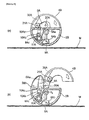
- Figure 12 is two fragmentary sectional views of the XII-XII section in drawing 10 of the toy shown in drawing 8, (a) showing a pre-transformacion state, and (b) showing a post-transformation state;
- Figure 13 is a left side view of the toy shown in drawing 8, showing a post-transformation state;
- Figure 14 is a plane view of the toy shown in drawing 8. showing a post-transformation state; and
- Figure 15 is a perspective view of the toy shown in drawing 8, showing a post-transformation state.
-
Toy 1 pertaining toembodiment 1 of the present invention shall be described below with reference to drawings 1-7.Toy 1 pertaining to the present embodiment is an item that transforms from a rollable, spherical shape (the first shape: drawings 2-4) to a fictitious character shape (the second shape: drawing 7) symbolizing a "malevolent angel" by means of the action of a magnetic force. - Firstly, the construction of
toy 1 pertaining to the present embodiment shall be described. - As shown in drawings 1-4, toy I is constructed of an exterior structure assigned to the exterior of
toy 1, which forms an overall spherical shape, and an interior structure contained within the interior of the exterior structure. The exterior structure is endowed with alower component 2 that constitutes the lower section oftoy 1, anupper component 3 that constitutes the upper section oftoy toy 1. Further, the interior structure is endowed with afront component 8 assigned to the front interior location oftoy 1, which constitutes the anterior portion of the character, aback component 9 assigned to the back interior location oftoy 1, which constitutes the posterior portion of the character, alocking component 10 assigned to the interval betweenfront component 8 andback component 9, amagnet 11 fixed to the lower end oflocking component 10, aspring 12 that effects a force which moveslocking component 10 upwardly, and supportcomponents back component 9, which support lateral components 4-7. - As shown in drawings 1-3,
lower component 2 of the exterior structure expresses a slight dome shape, as if it were a section of a sphere that has been cut off, and the exterior surface thereof constitutes one section (the lower section) of the spherical shape. As shown indrawings hole 2a is furnished in the central region oflower component 2. Lockingcomponent 10,magnet 11 andspring 12 of the interior structure are assigned to the interior space of through-hole 2a in such a way that they can move in the interval between the central location and near-surface location oftoy 1 in a rectilinear fashion. Here, as shown in drawing 5, there is a space formed for the movement of the magnet in the interval betweenmagnet 11 and the near-surface vicinity oftoy 1. Locking component 10etc. for these components shall be described in detail below. - As shown in drawings 1-3,
upper component 3 of the exterior structure expresses a slight dome shape, as if it were a section of a sphere that has been cut off, and the exterior surface thereof constitutes one section (the upper section) of the spherical shape. As shown indrawings concave portion 3a is formed within the interior ofupper component 3 in order to containfront component 8 and the upper portion of back component 9 (the head portion of the character). Further, as shown indrawings notch portion 3b is furnished in the marginal portion ofupper component 3. Back protrudingportion 9a ofback component 9 of the interior structure is inlaid in thisnotch portion 3b. And, as shown in drawing 2.upper component 3 is connected to back protrudingportion 9a ofback component 9 through turningaxis 20 in such a way that it can turn. Here,upper component 3 is biased in such a way that it turns upwardly (namely, the direction in which it separates with respect to back component 9) by means of the elastic force ofspring 30 assigned to the interval betweenupper component 3 andback component 9. - Further, as shown in
drawings convex portion 3c is furnished in the location oppositenotch portion 3b of the marginal portion ofupper component 3, and thisconvex portion 3c is such that it locks ontoconvex portion 4b oflateral component 4. As shown in drawing 6(a), in the event thatlateral component 4 is closed,upper component 3 does not turn upwardly due toconvex portion 3c ofupper component 3 being locked ontoconvex portion 4b oflateral component 4. On the contrary, as shown in drawing 6(b), in the event thatlateral component 4 is opened laterally,upper component 3 turns upwardly by means of the elastic force ofspring 30, due to the locked state ofconvex portion 3c ofupper component 3 andconcave portion 4b oflateral component 4 being released. - As shown in drawing 1 etc., lateral components 4-7 of the exterior structure are husk-shaped components with a roughly circular arc shape, endowed with a particular thickness and width, and the exterior surfaces thereof constitute one section (the circular section forming the upper and lower central region) of the spherical shape by means of them combining.
Bearing portions 4a-7a are furnished on one end of lateral components 4-7. Therespective bearing portions lateral components drawings notch portion 13a ofsupport component 13. And, these right-side lateral components component 13 through turningaxis 21. Here,lateral component 4 is biased in such a way that it turns outwardly (namely, the direction in which it opens) by means of the elastic force ofspring 31, which is assigned to the interval betweenlateral component 4 andsupport component 13. On the contrary, therespective bearing portions lateral components drawings support component 14. And, these left-side lateral components component 14 through turningaxis 22. Here,lateral component 6 is biased in such a way that it turns outwardly (namely, the direction in which it opens) by means of the elastic force ofspring 32, which is assigned to the interval betweenlateral component 6 andsupport component 14. - Further,
protrusions lateral components drawings Protrusion 5b of rightside lateral component 5, which is assigned to the lower section, is inlaid in a groove portion of rightside lateral section 4, which is assigned to the upper section, and is not shown in the drawings. By means of this, when upper rightside lateral component 4 turns upon turningaxis 21 by means of the elastic force ofspring 31, lower rightside lateral component 5 turns integrally with thislateral component 4. Further,protrusion 7b of left sidelateral section 7, which is assigned to the lower section, is inlaid in a groove portion of left sidelateral section 6, which is assigned to the upper section, and is not shown in the drawings. By means of this, when upper left sidelateral component 6 turns upon turningaxis 22 by means of the elastic force ofspring 32, lower left sidelateral component 7 turns integrally with thislateral component 6. - Further, as shown in
drawings exterior locking portions interior locking portions component 10 of the interior structure, are furnished on the inner side of the two left and rightlateral components drawings toy 1 and lockingcomponent 10 of the interior structure is upwardly biased by means of the elastic force ofspring 12,lateral components exterior locking portion 5c of rightside lateral component 5 andexterior locking portion 7c of left sidelateral component 7 being locked respectively onto right sideinterior locking portion 10c and left sideinterior locking portion 10c. On the contrary, as shown in drawing 5(b), in the event that a magnetic force has acted ontoy 1 and lockingcomponent 10 of the interior structure has moved downwardly,lateral components 4 and 6 (andlateral components springs interior locking portions component 10 andexterior locking portions lateral components - Furthermore, lateral components 4-7 of the exterior structure correspond to the first exterior turning component in the present invention, and turning
axes upper component 3 corresponds to the second exterior turning component in the present invention, and turningaxis 20 corresponds to the second exterior turning axis in the present invention. Further,spring 30, which effects a force that turnsupper component 3, and springs 31 and 32, which effect a force that turns lateral components 4-7, correspond to the turning means and transformation means in the present invention. - As shown in
drawings front component 8 andback component 9 of the interior structure are assigned to the upper section oflower component 2 of the exterior structure, and constitute the body portion and head portion of the character by means of being combined and held together byscrew 40. As shown in drawing 5, there is a space formed within in the interior of the back portion, which is constructed of the combination offront component 8 andback component 9, in order to house the vertical movement of lockingcomponent 10. This space is formed from the central location oftoy 1 towards the near-surface location oftoy 1 in such a way that it is in communication with the interior space of through-hole 2a oflower component 2, and is such that this space andmagnet 11 are aligned in a near-rectilinear fashion. Further,support components back component 9. - As shown in
drawings component 10 of the interior structure expresses a roughly T-shape and is endowed with a left-and-right extending portion 10a that extends in the left and right directions, and a taperedtubular portion 10b that extends downwards from the center of left-and-right extending portion 10a. And,interior locking portions right extending portion 10a, andmagnet 11 is fixed onto the bottom end of taperedtubular portion 10b.Interior locking portions exterior locking portions magnet 11 is assigned to a location near the surface of toy 1 (the surface oflower component 2 of the exterior structure). As shown in drawing 5, the lower end ofspring 12 is supported by means of support portion 2b, which is furnished on through-hole 2a oflower component 2, and is effected by an elastic force that propels the peripheral surface of taperedtubular portion 10b of lockingcomponent 10 upwardly. Furthermore,magnet 11 corresponds to the magnetic body in the present invention, andspring 12 corresponds to the biasing means in the present invention, - Next, the transformation action of
toy 1 pertaining to the present embodiment shall be described. - In the event that no metallic or other magnetic substance exists near
magnet 11 of the interior structure oftoy 1,magnet 1 1 does not move by means of a magnetic force, and lockingcomponent 10 is thereby maintained in a state of being pressed from the exterior towards the central region of toy I by means of the elastic force ofspring 12 of the interior structure. As shown in drawing 5(a), in this state,exterior locking portions interior locking portions component 10 of the interior structure, and the spherical shape (the first shape) of the exterior structure as shown in drawings 2-4 is thereby maintained. - On the contrary, as shown in drawing 5(b), in the event that a metallic or other magnetic substance (metal-embedded card M) exists near
magnet 11 of the interior structure oftoy 1, a magnetic force that attractsmagnet 11 and the magnetic substance acts. By means of the action of such a magnetic force, magnetic 11 and lockingcomponent 10 of the interior structure oftoy 1 resist the elastic force ofspring 12 and move integrally from the central location towards the exterior oftoy 1, and the locked state of the left and rightinterior locking portions component 10 of the interior structure andexterior locking portions - Hereby, the exterior structure transforms to the character shape (the second shape) as shown in drawing 7 by means of
springs interior locking portions exterior locking portions springs upper component 3 turns upwardly by means of the elastic force ofspring 30, due to the locked state ofconvex portion 3c ofupper component 3 andconcave portion 4b oflateral component 4 being released by means of the turning of lateral components 4-7. - Further, to restore the shape of
toy 1 from the character shape (the second shape) to the spherical shape (the first shape), first, work against the elastic force ofspring 30 and turnupper component 3 of the exterior structure downwardly. Next, work against the elastic force ofsprings convex portion 3c ofupper component 3 andconcave portion 4b oflateral component 4 while also lockingexterior locking portions interior locking portions toy 1 is restored to a spherical shape. And, the spherical shape oftoy 1 is maintained until a magnetic force acts once again. - In
toy 1 pertaining to the embodiment described above,toy 1 can maintain a rollable, spherical shape (the first shape) until a force (magnetic force) that attracts magnet I 1 acts from the exterior oftoy 1. Consequently, the realization of games such as shooting games in which toy I pertaining to the present embodiment is sent running through a travel motion toy, for example, is potentiated. Further, simply by effecting a magnetic force from the exterior oftoy 1,magnet 11 and lockingcomponent 10 within the interior oftoy 1 move, and the locked state ofinterior locking portions exterior locking portions toy 1 is relatively simple, the realization of the miniaturization of the toy is also potentiated. Hereby, the commercial value of the toy can be dramatically increased, and the impartation of fresh wonderment and intellectual excitement to its players is potentiated. - Further, in
toy 1 pertaining to the embodiment described above, the exterior structure is constructed in such a way that it is restorable from the character shape (the second shape) to the spherical shape (the first shape), and moreover, in the event that the exterior structure has been restored to the spherical shape, a locked stare ofinterior locking portions 1 0c and 10c andexterior locking portions toy 1 has transformed from the spherical shape to the character shape by means of the action of a magnetic force,toy 1 can be restored to a rollable, spherical shape and re-used, and games such as shooting games can hence be carried out repeatedly. - Next,
toy 1A pertaining toembodiment 2 of the present invention shall be described with reference to drawings 8-15.Toy 1A pertaining to the present embodiment is an item that transforms from a rollable, spherical shape (the first shape: drawings 9-11) to a fictitious character shape (the second shape: drawings 13-15) symbolizing a "fiendish dragon" by means of the action of a magnetic force. - Firstly, the construction of
toy 1A pertaining to the present embodiment shall be described. - As shown in drawings 8-11,
toy 1A is constructed of an exterior structure assigned to the exterior oftoy 1A, which forms an overall spherical shape, and an interior structure contained within the interior of the exterior structure. The exterior structure is endowed withhemispherical structure components toy 1 A,leg components toy 1A in such a way that they are turnable,central turning components toy 1A in such a way that they are turnable, andlateral turning components toy 1A in such a way that they are turnable. Further, the interior structure is endowed with aninterior turning component 8A assigned to the interior of the hemispherical portion oftoy 1 A in such a way that it is turnable, amagnet 9A fixed to the lower section ofinterior turning component 8A, aturning locking component 10A that turns simultaneously with the turning ofinterior turning component 8A, aspring 11 that effects a force which turns turninglocking component 10A in a particular direction, etc. - As shown in drawing 8,
hemispherical structure components bolt 40A. A hollow portion is formed within the hemispherical portion, which is constructed by means ofhemispherical structure components interior turning component 8A,magnet 9A, turninglocking component 10A, etc. of the interior structure are contained within this hollow portion. Further,a hole portion is formed on the lower section of the hemispherical portion, which is constructed by means ofhemispherical structure components magnet 9A is exposed to the exterior from this hole portion.Interior turning component 9A etc. shall be described in detail below. - As shown in
drawings leg components hemispherical structure components drawings leg components drawings leg components leg components - As shown in drawings 8-10,
central turning components drawings central turning components hemispherical structure components turning component 5A. First bearing portions 2Aa and 2Ba are furnished on the upper portion ofhemispherical structure components turning component 5A respectively through left-and-rightdirection turning axis 20A (drawing 12) in such a way that they are turnable. One end of connectingturning component 5A is connected to the first bearing portions 2Aa and 2Ba of thesehemispherical structure components axis 20A in such a way that it is turnable. Further, the other end of connectingturning component 5A is connected to one end ofcentral turning components axis 21A in such a way that it is turnable. Here, connectingturning component 5A is assigned to the interval betweencentral turning components central turning components spring 30 assigned to the interval between connectingturning component 5A andcentral turning components - Further, as shown in
drawings locking component 10A of the interior structure, is furnished on connectingturning component 5A. As shown in drawing 12(a), in the event that a magnetic force does not act ontoy 1A and interior locking portion 10Ac of the interior structure turns forwardly by means of the elastic force ofspring I 1A, connectingturning component 5A andcentral turning components turning component 5A being locked onto interior locking component 10Ac. On the contrary, as shown in drawing 12(b), in the event that a magnetic force has acted ontoy 1A and interior locking portion 10Ac of the interior structure has turned backwardly,central turning components spring 30A, due to the locked state of interior locking portion 1OAc and exterior locking portion 5Aa being released. Hereupon, the exterior surfaces ofcentral turning components hemispherical structure component 2B, andcentral turning components turning component 5A are propelled upwardly by means of the reactive force from this convex portion 2Bb. Further,central turning components lateral turning components springs central turning components turning component 5A turn upwardly and forwardly. - Further,
horn component 6A is connected in the interval betweencentral turning components axis 22A in such a way that it is turnable. As shown in drawings 13-15,horn component 6A can be used as the horn portion of the character by means of the player grasping the tip thereof with his/her fingers and turning it a predetermined angle. As shown in drawings 9-11, in the event thathorn component 6A is not used as the horn portion, the exterior surface ofhorn component 6A is such that it constitutes one section of the spherical shape. - As shown in drawings 8-11 etc.,
lateral turning components hemispherical structure components drawings lateral turning components hemispherical structure components hemispherical structure components lateral turning components direction turning axes lateral turning components hemispherical structure components axes lateral turning components springs lateral turning components hemispherical structure components - As shown in drawing 12(a), in the event that a magnetic force does not act on
toy 1A andcentral turning components turning component 5A do not turn,lateral turning components lateral turning components central turning components toy 1A andcentral turning components lateral turning components central turning components lateral turning components central turning components lateral turning components - Furthermore,
central turning components turning component 5A of the exterior structure correspond to the first exterior turning components in the present invention, and turningaxes lateral turning components axes spring 30A, which effects a force that turnscentral turning components lateral turning components - As shown in
drawings interior turning component 8A of the interior structure is endowed with large circular tubular portion 8Aa, extending portion 8Ab furnished in such a way that it extends in one direction from large circular tubular portion 8Aa, and two protrusions 8Ac and 8Ac furnished in such a way that they extend from large circular tubular portion 8Aa in a roughly perpendicular direction to the extension direction of extending portion 8Ab. Large circular tubular portion 8Aa ofinterior turning component 8A is connected withbolt 40B to turning axis portion 2Bb, which is furnished in the interior ofhemispherical structure component 2B. By means of this,interior turning component 8A is turnable upon the left-and-right direction turning axis (the first interior turning axis). Further,magnet 9A is fixed on the lower end of extending portion 8Ab ofinterior turning component 8A. As shown in drawing 12,magnet 9A is assigned to a location near the surface oftoy 1A (the surface ofhemispherical structure components magnet 9A to turn is furnished in the interval betweenmagnet 9A and the near-surface location oftoy 1A, and this space andmagnet 9A are positioned in a near-rectilineal' fashion in the interval between the central location oftoy 1A and the near-surface location oftoy 1A. - As shown in
drawings locking component 10A of the interior structure is endowed with small circular tubular portion 10Aa, protrudingportion 1 0Ab furnished in such a way that it protrudes in one direction from small circular tubular portion 10Aa, and L-shaped interior locking portion 10Ac furnished in such a way that it extends from small circular tubular portion 10Ac in an opposite direction to protruding portion 10Ab. Small circular tubular portion 10Aa of turninglocking component 10A is connected throughpin 50A to interior bearing portion 2Be, which is furnished in the interior ofhemispherical structure component 2B. By means of this, turninglocking component 10A is turnable upon the left-and-right direction turning axis (the second interior turning axis). Here, turninglocking component 10A is biased in such a way that it turns in a particular direction (the direction in which interior locking portion 10Ac, which is positioned on the upper section, turns forwardly) by means of the elastic force ofspring 11A, which is assigned to the interval between turninglocking component 10A andhemispherical structure component 2B. As shown in drawing 12, protruding portion 10Ab of turninglocking component 10A is inlaid in the interval between the two protrusions 8Ac and 8Ac ofinterior turning component 8A in such a way that it is swingable. Further, interior locking portion 10Ac ofinterior turning component 8A is locked onto exterior locking portion 5Aa of connectingturning component 5A of the exterior structure. Furthermore,interior turning component 8A of the interior structure corresponds to the first interior turning portion in the present invention, turninglocking component 10A corresponds to the second interior turning portion in the present invention, andspring 11A corresponds to the biasing means in the present invention. - Next, the transformation action of
toy 1A pertaining to the present embodiment shall be described, - In the event that no metallic or other magnetic substance exists near
magnet 9A of the interior structure oftoy 1A,magnet 9A does not move by means of a magnetic force, and turninglocking component 10A is thereby maintained in a state of being biased in a particular direction (the direction in which interior locking portion 10Ac, which is positioned on the upper section, turns forwardly) by means of the elastic force ofspring 11A of the interior structure. As shown in drawing 12(a), in this state, exterior locking portion 5Aa of connectingturning component 5A of the exterior structure is locked by interior locking portion 10Ac of turninglocking component 10A of the interior structure, and the spherical shape of the exterior structure as shown in drawings 9-11 is thereby maintained. - On the contrary, as shown in drawing 12(b), in the event that a metallic or other magnetic substance (metal-embedded card M) exists near
magnet 9A of the interior structure oftoy 1A, a magnetic force that attractsmagnet 9A and the magnetic substance acts. By means of this,magnet 9A of the interior structure andinterior turning component 8A of the interior structure oftoy 1A turn integrally in direction R1 of drawing 12. Wheninterior turning component 8A turns in such a way, protruding portion 10Ab of turninglocking component 10A, which is inlaid in the two protrusions 8Ac and 8Ac ofinterior turning component 8A, swings forwardly, and the locked state of interior locking portion 10Ac of turninglocking component 10A and exterior locking portion 5Aa of connectingturning component 5A is released due to turninglocking component 10A turning in direction R2 of drawing 12. - Hereby, the exterior structure transforms to the character shape (the second shape) as shown in drawings 13-15 by means of
springs central turning components turning component 5A turn by means of the elastic force ofspring 30A. Next,lateral turning components springs lateral turning components central turning components - Further, to restore the shape of
toy 1A from the character shape (the second shape) to the spherical shape (the first shape), first, work against the elastic force ofsprings lateral turning components spring 30 and turncentral turning components turning component 5A backwardly, and lock exterior locking portion 5Aa of the exterior structure and interior locking portion 10Ac of the interior structure, By means of such an operation, the shape of the exterior oftoy 1A is restored to a spherical shape. And, the spherical shape oftoy 1A is maintained until a magnetic force acts once again. - In
toy 1A pertaining to the embodiment described above,toy 1 A can maintain a rollable, spherical shape (the first shape) until a force (magnetic force) that attractsmagnet 9A acts from the exterior oftoy 1A Consequently, the realization of games such as shooting games in whichtoy 1A pertaining to the present embodiment is sent running through a travel motion toy, for example, is potentiated. Further, simply by effecting a magnetic force from the exterior oftoy 1 A,magnet 9A andinterior turning component 8A within the interior oftoy 1A turn, and the locked state of interior locking portion 10Ac of the interior structure and exterior locking component 5Aa of the exterior structure is thereby released, andtoy 1A can hence automatically transform from the spherical shape to the character shape (the second shape). Consequently, by positioning a metallic etc. magnet in a particular location on a travel motion toy, for example, the sudden transformation oftoy 1A traveling on the travel motion toy in a rollable, spherical shape to a different shape (the second shape), on this particular location, is potentiated. Further, because the mechanism for transforming toy IA is relatively simple, the realization of the miniaturization of the toy is also potentiated. Hereby, the commercial value of the toy can be dramatically increased, and the impartation of fresh wonderment and intellectual excitement to its players is potentiated. - Further, in
toy 1A pertaining to the embodiment described above, the exterior structure is constructed in such a way that it is restorable from the character shape (the second shape) to the spherical shape 9the first shape), and moreover, in the event that the exterior structure has been restored to the spherical shape, a locked state ofinterior locking portion 1 0Ac and exterior locking portion 5Aa is realized, and this spherical shape is thereby maintained once again. Consequently, even aftertoy 1A has transformed from the spherical shape to the character shape by means of the action of a magnetic force,toy 1A can be restored to a rollable, spherical shape and re-used, and games such as shooting games can hence be carried out repeatedly. - Furthermore, the present invention is not limited to the above embodiments; a variety of transformations are possible without departing from the scope thereof. For example, in the above embodiments, although examples of the realization of the transformation of the toy by menus of placing a magnet in the interior of the toy in such a way that it is movable (turnable) and placing a metallic or other magnetic substance at the exterior of the toy and causing the magnetic inside the toy to move (turn) have already been shown, the transformation of the toy may also be realized by means of placing a metallic or other magnetic substance in the interior of the toy in such a way that it is movable (turnable) and placing a magnet at the exterior of the toy, which attracts the magnetic substance inside the toy and causes it to move (turn).
- Further, in the above embodiments, although examples of the realization of the transformation of the toy by means of attracting the magnetic substance (magnet) inside the toy and causing it to move from the central location to the near-surface location of the toy have already been shown, the aspect of the moving (turning) of the magnetic substance (magnet) inside the toy is not limited to this. For example, the employment of a structure that causes the magnetic substance inside the toy to move (turn) from the near-surface location to the central location of the toy, by means of causing the magnetic pole of the magnetic substance on the exterior and the magnetic pole of the magnetic substance inside the toy to repel each other and thereby realize the transformation of the toy, is also possible. To employ such a structure, interchange the magnet assigned to the interval between the central location of the toy and the near-surface location of the toy (for example,
magnets - Further, in the above embodiments, although examples in which a "spherical shape" is employed as the first shape of the toy have already been shown, other rollable shapes (a rugby ball shape or a circular, tubular shape, for example) can also be employed as the first shape of the toy. Further, the second shape of the toy is also not particularly limited, a variety of shapes can be employed.
- Further, in the above embodiments, although examples in which springs were employed as the biasing means, transformation means and turning means, rubber or other elastic bodies can also be employed as the biasing means, etc.
-
- 1 & 1A
- Toy
- 3
- Upper component (the second exterior turning component)
- 4-7
- Lateral components (the first exterior turning components)
- 4A & 4B
- Central turning components (the first exterior turning components)
- 5A
- Connecting turning component (the first exterior turning component)
- 7A & 7B
- Lateral turning components (the second exterior turning components)
- 5c, 7c & 5Aa
- Exterior locking portions
- 8A
- Interior turning component (the first interior turning portion)
- 10A
- Turning locking component (the second interior turning portion)
- 10c & 10Ac
- Interior locking portion
- 11 & 9a
- Magnet (magnetic body)
- 12 & 11A
- Springs (biasing means)
- 20
- Turning axis (the second exterior turning axis)
- 21 & 22
- Turning axes (the first exterior turning axes)
- 30, 31 & 32
- Springs (transformation means, turning means)
Claims (13)
- A toy characterized by a toy equipped with an exterior structure, constructed in such a way that it transforms from a rollable first shape to a second shape, and an interior structure contained within the interior of this exterior structure, and
wherein the said exterior structure is endowed with a transformation means that transforms an exterior locking portion and the said exterior structure from the said first shape to the said second shape, and
wherein the said interior structure is endowed with a magnetic body that moves by means of a magnetic force that acts from the exterior of the said toy, an interior locking portion that moves simultaneously with the movement of this magnetic body, and a biasing means that effects a force which moves or turns this interior locking portion in a particular direction, and
wherein, in the event that a magnetic force does not act from the exterior of the said toy, a locked state of the said interior locking portion, which moved or turned in a particular direction by means of the force of the said biasing means, and the said exterior locking portion is realized, and the first shape of the said exterior structure is thereby maintained, and
wherein, on the contrary, in the event that a magnetic force has acted from the exterior of the said toy, the said magnetic body and the said interior locking portion resist the force of the said biasing means and move or turn, the locked state of the said interior locking portion and the said exterior locking portion is thereby released, and the said exterior structure thereby transforms from the said first shape to the said second shape by means of the said transformation means, - The toy as defined in claim 1 characterized by the said interior locking portion being one that moves integrally with the said magnetic body in the interval between the central location and near-surface location of the said toy in a rectilinear fashion, and
wherein the said biasing means is one that effects a force which moves the said interior locking portion from the near-surface location towards the central location of the said toy. - The toy as defined in claim 1 characterized by the said interior structure being endowed with a first interior turning portion that turns integrally with the said magnetic body upon a first interiorturning axis, and a second interior turning portion that turns upon a second interior turning axis simultaneously with the turning of the said first interior turning portion, and
wherein the said interior locking portion is one that turns integrally with the said second interior turning portion, and
wherein the said biasing means is one that effects a force which turns the said second interior turning portion and the said interior locking portion in a particular direction. - The toy as defined in any of claims 1 through 3 characterized by the said exterior structure being endowed with a first exterior turning component that turns upon a first exterior turning axis, and a second exterior turning component that turns upon a second exterior turning axis, and
wherein the said transformation means is a turning means that effects a force which turns the said first and second exterior turning components. - The toy as defined in any of claims 1 through 4 characterized by being constructed in such a way that, in the event that a magnetic force has acted from the exterior of the said toy and the locked state of the said interior locking portion and the said exterior locking portion has been released, the turning of the said first exterior turning component and the turning of the said second exterior turning component is realized, in this order.
- The toy as defined in any of claims 1 through 5 characterized by the said first shape of the said exterior structure being a roughly spherical shape.
- The toy as defined in any of claims 1 through 6 characterized by the said exterior structure being constructed in such a way that it is restorable from the said second shape to the said first shape, and
wherein it is constructed in such a way that, in the event that the said exterior structure has been restored from the said second shape to the said first shape, a locked state of the said interior locking portion and the said exterior locking portion is realized, and the said first shape of the said exterior structure is thereby maintained once again. - A toy comprising a main body element and at least one first moveable element associated with said main body and moveable with respect thereto from a first position adjacent said main body, to a second position in which at least a portion of a said first moveable element has moved away from said main body, said at least one first moveable element being permanently biased toward said second position, and being provided with catch means co-operable with releasable latch means in said main body element to maintain at least one said first moveable element in said first position until said latch means is released.
- A toy as claimed in claim 8, wherein said main body element, together with said at least one first moveable element, are a first shape when said at least one first moveable element is in said first position, and a second shape when said at least one first moveable element is in said second position.
- A toy as claimed in claim 9, wherein said first shape is selected from the group consisting of spheres, cubes, tetrahedrons, pyramids, triangular prisms, egg shapes, parallelpipids, cylinders, discus shapes, toruses, teardrops, lozenges, animal shapes, planet shapes, robot shapes, vehicle shapes, building shapes, tree shapes, sports equipment related shapes, weapons shapes, character-head shapes, and the like.
- A toy as claimed in claim 10, wherein said releasable latch is biased to a position in engagement with said catch.
- A toy as claimed in claim 11, wherein said releasable latch is provided with a magnet, whereby said releasable latch may be moved out of engagement with said catch by attraction of said magnet to a ferrous or other magnetic metal surface, or a second magnet.
- A toy as claimed in claim 12, further comprising at least one second moveable element. hinged to said at least one first moveable element and moveable from a close position adjacent said at least one first moveable element, to an open position away from said at least one first moveable element, said at least one second moveable element being biased toward said open position, and foldable to said closed position, said at least one second moveable element being restrained against movement toward said open position while said catch is in engagement with said releasable latch.
Applications Claiming Priority (1)
| Application Number | Priority Date | Filing Date | Title |
|---|---|---|---|
| JP2006041918A JP4859206B2 (en) | 2006-02-20 | 2006-02-20 | toy |
Publications (2)
| Publication Number | Publication Date |
|---|---|
| EP1820548A1 true EP1820548A1 (en) | 2007-08-22 |
| EP1820548B1 EP1820548B1 (en) | 2011-05-25 |
Family
ID=38109572
Family Applications (1)
| Application Number | Title | Priority Date | Filing Date |
|---|---|---|---|
| EP07250653A Active EP1820548B1 (en) | 2006-02-20 | 2007-02-16 | Transformable toy |
Country Status (12)
| Country | Link |
|---|---|
| US (7) | US7785168B2 (en) |
| EP (1) | EP1820548B1 (en) |
| JP (1) | JP4859206B2 (en) |
| KR (1) | KR101452244B1 (en) |
| CN (1) | CN101389386B (en) |
| AT (1) | ATE510604T1 (en) |
| AU (1) | AU2007200737B2 (en) |
| BR (1) | BRPI0706815B8 (en) |
| CA (1) | CA2547539C (en) |
| ES (1) | ES2367184T3 (en) |
| MX (1) | MX2008010661A (en) |
| WO (1) | WO2007097326A1 (en) |
Cited By (8)
| Publication number | Priority date | Publication date | Assignee | Title |
|---|---|---|---|---|
| EP2116289A1 (en) * | 2008-05-09 | 2009-11-11 | Produzioni Editoriali Aprile S.p.A. | Transformable toy |
| CN101898043A (en) * | 2010-08-19 | 2010-12-01 | 广东奥飞动漫文化股份有限公司 | Transforming disc toy |
| WO2015159077A3 (en) * | 2014-04-15 | 2015-12-10 | Asque Limited | Article moveable between two positions and a method of combining two or more of the same |
| WO2019048814A1 (en) * | 2017-09-08 | 2019-03-14 | Boti Global Limited | Article moveable between two positions and a method of combining two or more of the same |
| EP3393611A4 (en) * | 2015-12-24 | 2019-06-12 | Boti Global Ltd | MOBILE ARTICLE BETWEEN TWO POSITIONS AND A METHOD OF COMBINING AT LEAST TWO OF THEM |
| EP4331697A1 (en) * | 2022-08-12 | 2024-03-06 | Spin Master Ltd. | Transformable toy |
| USD1100069S1 (en) | 2022-08-12 | 2025-10-28 | Spin Master Ltd. | Toy |
| US12576341B2 (en) | 2022-08-12 | 2026-03-17 | Spin Master Ltd. | Transformable toy |
Families Citing this family (70)
| Publication number | Priority date | Publication date | Assignee | Title |
|---|---|---|---|---|
| JP4859206B2 (en) * | 2006-02-20 | 2012-01-25 | 株式会社セガ トイズ | toy |
| KR20100126674A (en) | 2008-01-10 | 2010-12-02 | 가부시키가이샤 세가 토이즈 | toy |
| JP2009189521A (en) * | 2008-02-14 | 2009-08-27 | Tomy Co Ltd | Shape change toy |
| JP2009189520A (en) * | 2008-02-14 | 2009-08-27 | Tomy Co Ltd | Shape change toy |
| JP2009213668A (en) * | 2008-03-10 | 2009-09-24 | Tomy Co Ltd | Figure changing toy |
| JP5606033B2 (en) * | 2008-11-04 | 2014-10-15 | 株式会社セガ トイズ | Deformed toy |
| JPWO2010073910A1 (en) * | 2008-12-26 | 2012-06-14 | 株式会社セガ トイズ | Mobile accessories and decorative toys |
| US9526998B2 (en) | 2009-04-06 | 2016-12-27 | Jakks Pacific, Inc. | Spinning toy with trigger actuated stop mechanism |
| JP2011120756A (en) * | 2009-12-11 | 2011-06-23 | Tomy Co Ltd | Transformable toy |
| PH12012501497A1 (en) * | 2010-07-09 | 2022-10-24 | Jakks Pacific Inc | Core with finger indentation and formed to expel an object concealed therein |
| US9993739B2 (en) | 2010-12-21 | 2018-06-12 | David Weeks Studio LLC | Transformable toy robot |
| US8814629B2 (en) | 2011-06-21 | 2014-08-26 | Andrew Lewis Johnston | Non-rollable to rollable transforming toy |
| KR101327305B1 (en) | 2012-02-24 | 2013-11-11 | 최신규 | Transform toy car and playing device using the same |
| US20130244535A1 (en) * | 2012-03-13 | 2013-09-19 | Mattel, Inc. | Toys with pivotal members |
| WO2013173937A1 (en) * | 2012-05-24 | 2013-11-28 | Blanco Publicidad Y Marketing Limitada | Toy comprising two bodies and including a pop-out gear |
| US9108116B2 (en) * | 2012-10-03 | 2015-08-18 | Paul Swartz | Container with articulatable statuette |
| KR101375110B1 (en) * | 2012-12-20 | 2014-03-17 | 최신규 | Transformation toy |
| US10173143B2 (en) * | 2013-01-31 | 2019-01-08 | Joshua Willard Ferguson | Magnetic construction system and method |
| US9067147B1 (en) | 2013-02-28 | 2015-06-30 | Hasbro, Inc. | Toy figure combiners |
| US9101847B2 (en) * | 2013-03-15 | 2015-08-11 | Bang Zoom Design, Ltd. | Shape changing apparatus and method |
| KR101400980B1 (en) * | 2013-04-03 | 2014-05-29 | 최신규 | Transformable toy car |
| WO2014175461A1 (en) * | 2013-04-26 | 2014-10-30 | Fukui Osamu | Accessory/decoration that opens like a flower |
| JP5937160B2 (en) * | 2014-08-29 | 2016-06-22 | 株式会社Area81 | Deformed block toy |
| KR101746917B1 (en) * | 2015-05-11 | 2017-06-27 | 최종일 | Pop up toy |
| WO2016182096A1 (en) * | 2015-05-12 | 2016-11-17 | 최종일 | Transforming toy |
| KR101635319B1 (en) * | 2015-06-12 | 2016-06-30 | 최종일 | Transformable toy |
| KR101859804B1 (en) * | 2015-11-20 | 2018-05-18 | 최종일 | Separative toy |
| KR101815357B1 (en) * | 2015-12-07 | 2018-01-30 | 최종일 | Launchable toy |
| KR101815363B1 (en) * | 2016-01-13 | 2018-01-08 | 최종일 | Transformable toy having launcher |
| CN105771279B (en) * | 2016-02-29 | 2018-11-09 | 广东美奇林互动科技有限公司 | Electronic toy |
| KR101780148B1 (en) | 2016-05-13 | 2017-09-19 | 최종일 | Transformable toy |
| CN109562801B (en) * | 2016-05-19 | 2021-04-16 | 勇敢机器人技术株式会社 | shape-shifting robot |
| JP6831647B2 (en) * | 2016-06-17 | 2021-02-17 | 株式会社バンダイ | Motion doll |
| CN107537160B (en) * | 2016-06-27 | 2023-04-21 | 奥飞娱乐股份有限公司 | Toy capable of secondary coin clamping |
| US10035076B2 (en) | 2016-09-21 | 2018-07-31 | Mga Entertainment, Inc. | Transformer toy with rolling vehicle integrated into command center |
| CN206198683U (en) * | 2016-09-28 | 2017-05-31 | 奥飞娱乐股份有限公司 | Primary and secondary toy |
| EP4241861A3 (en) * | 2017-02-15 | 2024-01-03 | ZURU (Singapore) Pte. Ltd. | Apparatus for housing and revealing a plurality of children's toys |
| US11219839B2 (en) | 2017-12-06 | 2022-01-11 | Darwin William Fernandez | Button activated transformable rotating toy |
| US10695687B2 (en) | 2017-10-03 | 2020-06-30 | Darwin William Fernandez | Model Toy croms balls |
| MX2020003494A (en) * | 2017-10-03 | 2022-02-10 | Blanco Usa Bmp Llc | ROTATING MODEL TOY BALLS. |
| US10864452B2 (en) | 2018-01-22 | 2020-12-15 | Darwin William Fernandez | Toy with two bodies and an ejectable gear and retraction mechanism |
| JP6976979B2 (en) * | 2017-11-14 | 2021-12-08 | 株式会社バンダイ | Deformed toys and deformed toy sets |
| JP6481013B1 (en) * | 2017-11-14 | 2019-03-13 | 株式会社バンダイ | Modified toy and modified toy set |
| KR102022167B1 (en) * | 2017-12-15 | 2019-09-18 | 최신규 | Transforbable toy |
| JP6533602B1 (en) * | 2018-02-26 | 2019-06-19 | 株式会社タカラトミー | Form change toy |
| CN108837530A (en) * | 2018-07-27 | 2018-11-20 | 广州咏声动漫玩具有限公司 | A kind of spherical form deformation toy |
| EP3838360B1 (en) * | 2018-08-17 | 2024-06-05 | Sony Interactive Entertainment Inc. | Toy system, casing, separate toy, separate toy assessing method, and program |
| KR102030937B1 (en) * | 2018-09-21 | 2019-10-10 | 주식회사 초이락컨텐츠팩토리 | Transformable toy |
| JP7044688B2 (en) * | 2018-11-16 | 2022-03-30 | 株式会社バンダイ | Moving toys, articles, and toy sets |
| US11389741B2 (en) | 2018-12-12 | 2022-07-19 | Mattel-Mega Holdings (Us), Llc | Transformable building block |
| CN110251964B (en) * | 2018-12-29 | 2024-06-07 | 广东原创动力文化传播有限公司 | Polyhedral toy |
| KR102231701B1 (en) | 2019-05-13 | 2021-03-23 | 최신규 | Foldable toy |
| JP7281339B2 (en) * | 2019-05-23 | 2023-05-25 | 株式会社エポック社 | Model toys and pot toys |
| EP4037793B1 (en) * | 2019-10-01 | 2023-11-01 | Lego A/S | Transformable modular toy element |
| JP7325369B2 (en) * | 2020-03-25 | 2023-08-14 | 株式会社バンダイ | transforming toy |
| US11077379B1 (en) | 2020-03-30 | 2021-08-03 | Big Monster Toys Llc | Toy and play system |
| KR102470349B1 (en) * | 2020-08-03 | 2022-11-25 | 주식회사 영실업 | Transformable toy and transformable toy system comprising thereof |
| US12370458B2 (en) * | 2021-02-15 | 2025-07-29 | Spin Master Ltd. | Toy assembly with enclosure with optional flaps and inner object |
| USD1029155S1 (en) | 2021-06-25 | 2024-05-28 | Spin Master Ltd. | Toy |
| JP7081026B1 (en) * | 2021-06-25 | 2022-06-06 | 株式会社バンダイ | toy |
| US11376515B1 (en) * | 2021-06-29 | 2022-07-05 | Spin Master Ltd. | Transformable toy |
| JP7311580B2 (en) * | 2021-12-20 | 2023-07-19 | 株式会社バンダイ | working toy |
| US12303801B2 (en) * | 2022-02-24 | 2025-05-20 | Timothy Forte | Transformable spherical ball toy |
| JP7606496B2 (en) * | 2022-10-19 | 2024-12-25 | 株式会社バンダイ | toy |
| US12472444B2 (en) | 2022-12-13 | 2025-11-18 | Lovefrom, Inc. | Bistable pivot hinge |
| KR102793203B1 (en) * | 2023-01-30 | 2025-05-12 | 주식회사 초이락컨텐츠컴퍼니 | Transformable toy for alccagi game |
| US12011675B1 (en) * | 2023-03-31 | 2024-06-18 | DiscoNifty Ltd. | Rotationally transformable toy between a first configuration and a second configuration |
| KR102822931B1 (en) * | 2023-04-17 | 2025-06-19 | (주)모꼬지 | Deformable multi-joint toy |
| US12134045B1 (en) * | 2023-05-03 | 2024-11-05 | Mattel, Inc. | Adjustable toy figure |
| DE202023105889U1 (en) * | 2023-10-11 | 2023-12-23 | 100 Greetings, LLC | Pop-up egg with sound |
Citations (5)
| Publication number | Priority date | Publication date | Assignee | Title |
|---|---|---|---|---|
| FR2559072A1 (en) * | 1984-02-03 | 1985-08-09 | Takara Co Ltd | Toy which can change state |
| US4606618A (en) * | 1985-05-23 | 1986-08-19 | Arco Industries | Optical device which is convertible to a toy robot |
| GB2217218A (en) * | 1988-04-15 | 1989-10-25 | Tomy Kogyo Co | Transformable block toys |
| WO2001056674A1 (en) * | 2000-02-03 | 2001-08-09 | Mattel, Inc. | Toy motorcycle configurable as a hovercycle |
| US20030016443A1 (en) * | 2001-07-19 | 2003-01-23 | Ouk-Kyon Shin | Binocular doubling as toy |
Family Cites Families (132)
| Publication number | Priority date | Publication date | Assignee | Title |
|---|---|---|---|---|
| US152250A (en) | 1874-06-23 | Improvement in toys | ||
| US1557751A (en) * | 1925-07-02 | 1925-10-20 | William M Parlett | Toy ball |
| US2277672A (en) | 1941-02-14 | 1942-03-31 | Ralph A Stone | Toy |
| US2809062A (en) | 1954-09-13 | 1957-10-08 | Mainhardt Robert | Latch mechanism |
| US2987852A (en) | 1958-05-26 | 1961-06-13 | Koch Fritz | Magnet toy |
| US3095723A (en) | 1962-05-23 | 1963-07-02 | Harry F Mcknight | Lock and magnetic release device |
| US3166322A (en) * | 1963-10-01 | 1965-01-19 | Branneman Leonard | Toy satellite system |
| US3401485A (en) | 1966-06-20 | 1968-09-17 | Leo Allen Goodrum Jr. | Magnetically activated toy dog |
| US3411237A (en) | 1966-11-03 | 1968-11-19 | Luxe Topper Corp De | Toy having magnetically actuatable appendage |
| US3520078A (en) | 1967-08-14 | 1970-07-14 | Klamer R B | Self-storing multicharactered toy |
| US3589059A (en) * | 1969-12-08 | 1971-06-29 | Craig Vaughn Caswell | Rotary accelerator for toys |
| US3626961A (en) * | 1970-03-11 | 1971-12-14 | Carlos Manuel Quinones | Magnetic hydrant lock |
| US3687452A (en) * | 1970-12-02 | 1972-08-29 | Rayford L Thompson | Game ball |
| US3684292A (en) * | 1970-12-03 | 1972-08-15 | Robert M Penrod | Puzzle toy |
| US3831986A (en) | 1972-08-09 | 1974-08-27 | S Kobayashi | Container having magnetic and latch fastening means |
| FR2314111A1 (en) | 1975-06-11 | 1977-01-07 | Poulain Bernard | Magnetically operated catch for opening or closing box lid - uses similar poles to open catch and opposite poles to close it |
| US4132032A (en) * | 1977-05-19 | 1979-01-02 | Triska Matej K | Toy with movable mouth |
| US4326235A (en) * | 1979-01-26 | 1982-04-20 | Hopkins Norman K | Container |
| JPS6122624Y2 (en) * | 1980-12-04 | 1986-07-07 | ||
| DE3048999A1 (en) | 1980-12-24 | 1982-07-15 | Robert Bosch Gmbh, 7000 Stuttgart | CIRCUIT ARRANGEMENT FOR ENERGY RECOVERY IN CHOPPER-CONTROLLED SERIES |
| GB2112407B (en) | 1981-12-14 | 1985-06-19 | Gen Electric | Method of hydrolyzing chlorosilanes |
| JPS58126893U (en) | 1982-02-23 | 1983-08-29 | 株式会社タイト− | Electronic game board with clock |
| JPS58165881A (en) | 1982-03-29 | 1983-09-30 | 株式会社 バンダイ | Wrist watch for toy |
| AU551205B2 (en) | 1982-03-29 | 1986-04-17 | Bandai K.K. | Toy robot having timepiece in torso |
| JPS58179191A (en) * | 1982-04-13 | 1983-10-20 | Mitsubishi Electric Corp | Torque detector for induction motor |
| JPS58179191U (en) * | 1982-05-25 | 1983-11-30 | 株式会社タカラ | traveling toy |
| GB2128489B (en) * | 1982-10-12 | 1986-08-20 | Takara Co Ltd | Reconfigurable toy assembly |
| JPS5991984A (en) | 1982-11-18 | 1984-05-26 | 山本 一郎 | Sounding ornamental bag |
| GB2137105A (en) | 1983-03-30 | 1984-10-03 | Wiggs C C | Jack-in-the-box type toy |
| JPS6055491U (en) | 1983-09-22 | 1985-04-18 | 株式会社タカラ | combination transformation toy |
| JPS60128693A (en) | 1983-12-15 | 1985-07-09 | オムロン株式会社 | Terminal of electronic device |
| USD287258S (en) | 1984-01-31 | 1986-12-16 | Takara Co., Ltd. | Reconfigurable toy robot |
| JPS60253480A (en) | 1984-05-30 | 1985-12-14 | 株式会社 タカラ | Shape change toy |
| JPS61115593A (en) | 1984-11-12 | 1986-06-03 | ジューキ株式会社 | Sewing machine |
| US4581904A (en) | 1984-12-20 | 1986-04-15 | Lehmann Roger W | Toy jewelry item with parts movable to a hidden position |
| JPH0234933Y2 (en) | 1984-12-28 | 1990-09-20 | ||
| JPS61159980A (en) | 1984-12-29 | 1986-07-19 | 株式会社 増田屋コ−ポレ−シヨン | Block toy deformable to robot |
| US4613004A (en) * | 1985-11-06 | 1986-09-23 | Hughes Tool Company - Usa | Earth boring bit with labyrinth seal protector |
| US4687459A (en) | 1985-11-06 | 1987-08-18 | Lockett G Jeffrey | Baby toy |
| CA1328474C (en) * | 1985-11-07 | 1994-04-12 | Roger Conington Richards | Magnetically operated latch |
| JPH0421589Y2 (en) * | 1985-12-27 | 1992-05-18 | ||
| JPS62155886A (en) | 1985-12-28 | 1987-07-10 | 株式会社 タカラ | Spring-out robot toy |
| US4696656A (en) | 1986-01-14 | 1987-09-29 | Mattel, Inc. | Reconfigurable toy |
| US4708687A (en) | 1986-02-07 | 1987-11-24 | Coleco Industries, Inc. | Rolling figure toy |
| US4817936A (en) | 1986-04-30 | 1989-04-04 | Takara Co., Ltd. | Spring-powered toy |
| US4698043A (en) * | 1986-05-09 | 1987-10-06 | May-Curran Associates | Rolling egg toy |
| JPS63122488A (en) | 1986-11-12 | 1988-05-26 | 株式会社 エ−ス電研 | Premium exchange apparatus of game area |
| JPH06160Y2 (en) * | 1987-01-31 | 1994-01-05 | 株式会社タカラ | Visiting rugged toys |
| JPS6456087A (en) | 1987-08-20 | 1989-03-02 | Fumiaki Hayashi | Trigger control device for movable toy |
| JPH01112893A (en) * | 1987-10-26 | 1989-05-01 | Mitsubishi Electric Corp | Action switching control system for electronic equipment |
| JPH01161797A (en) | 1987-12-18 | 1989-06-26 | Senju Metal Ind Co Ltd | Mounting method for electronic part and storecase for electronic part |
| JPH0622389Y2 (en) * | 1988-01-25 | 1994-06-15 | 株式会社センテクリエイションズ | Traveling toy displacement device |
| IT1219205B (en) | 1988-04-13 | 1990-05-03 | Ferrero Spa | COMPLEX OF GIFT ITEM AND RELATED WRAPPING PARTICULARLY FOR CHOCOLATE EGGS AND SIMILAR FOOD PRODUCTS CABLES AND PACKAGING PROCEDURE |
| US5019010A (en) | 1988-04-15 | 1991-05-28 | Tomy Company, Ltd. | Transformable block toys |
| JPH01161797U (en) | 1988-04-28 | 1989-11-10 | ||
| US4874340A (en) | 1988-07-21 | 1989-10-17 | Smallwood Alice R | Combined amusement device and transport and storage pack |
| JP2938098B2 (en) | 1989-09-27 | 1999-08-23 | 東芝セラミックス株式会社 | BN-SiC composite sintered body |
| JPH03112866U (en) * | 1990-03-01 | 1991-11-19 | ||
| US5209345A (en) | 1990-04-24 | 1993-05-11 | Connie Haugabook | Combination storage and display unit |
| US5090935A (en) | 1990-12-17 | 1992-02-25 | Monson Chris S | Composite toy having interconnectable toy components |
| US5169156A (en) * | 1991-02-13 | 1992-12-08 | Marchon, Inc. | Interactive action toy system |
| US5188405A (en) * | 1991-03-06 | 1993-02-23 | Rev-A-Shelf, Inc. | Locking device for a latch |
| US5090938A (en) | 1991-03-27 | 1992-02-25 | Christopher Reynolds | Toy or other object alterable between two different shapes |
| US5310378A (en) * | 1992-06-01 | 1994-05-10 | Shannon Suel G | Transformable toy |
| JP3199455B2 (en) | 1992-06-19 | 2001-08-20 | オリンパス光学工業株式会社 | Endoscope cleaning equipment |
| SE506232C2 (en) * | 1993-11-29 | 1997-11-24 | Mw Trading Aps | anti-theft |
| JP3001886U (en) | 1994-03-10 | 1994-09-06 | パイオニア精密株式会社 | binoculars |
| US5439408A (en) * | 1994-04-26 | 1995-08-08 | Wilkinson; William T. | Remote controlled movable ball amusement device |
| GB9507167D0 (en) * | 1995-04-06 | 1995-05-31 | Reilor Ltd | Improved pet door |
| US5855499A (en) | 1995-06-27 | 1999-01-05 | Kabushiki Kaisha Bandai | Packaging apparatus mounting a displayed article using a component of the article |
| WO1997045181A1 (en) | 1996-05-29 | 1997-12-04 | The All-Round Company Limited | Toy |
| JP3178705B2 (en) * | 1996-06-05 | 2001-06-25 | 株式会社タカラ | Working toy |
| US5672129A (en) * | 1996-11-15 | 1997-09-30 | Elliot Rudell | Game for projecting a projectile with a stick and coupling members for releasably attaching the projectile to the stick |
| US6126507A (en) | 1997-03-13 | 2000-10-03 | Chameleon Products, Inc. | Reversible doll/hat |
| US5893791A (en) * | 1997-06-02 | 1999-04-13 | Wilkinson; William T. | Remote controlled rolling toy |
| US5916007A (en) * | 1997-07-08 | 1999-06-29 | Maxim; John G. | Magnetically tripped spring wound vehicles |
| JP3112866B2 (en) | 1997-08-13 | 2000-11-27 | ジーイー横河メディカルシステム株式会社 | MR imaging method and MRI apparatus |
| US6086449A (en) * | 1998-01-15 | 2000-07-11 | Sharp; David F. | Cascading release fastener mechanism |
| US6261146B1 (en) | 1998-05-08 | 2001-07-17 | Donald Spector | Package containing a shrunken body |
| US6089950A (en) | 1998-06-01 | 2000-07-18 | C. J. Associates, Ltd. | Toy figure with articulating joints |
| US6225885B1 (en) * | 1999-01-08 | 2001-05-01 | Kuo Jung Lin | Switch device |
| US6592427B1 (en) | 1999-02-11 | 2003-07-15 | Learning Curve International, Inc. | Toy vehicle grain loader accessory |
| JP3001886B1 (en) | 1999-03-10 | 2000-01-24 | 英敏 西山 | Work protection cover and method of manufacturing the same |
| JP4260999B2 (en) | 1999-10-20 | 2009-04-30 | ブリヂストンスポーツ株式会社 | Golf club |
| US6231346B1 (en) | 1999-12-06 | 2001-05-15 | Snubelgrass Interactive Ltd. | Interactive hatching egg |
| US6261149B1 (en) | 2000-04-20 | 2001-07-17 | Shane A. Moore | Reversible doll toy |
| US6773329B2 (en) | 2000-10-02 | 2004-08-10 | All Season Toys, Inc. | Amusement device including a thematic play set |
| GB2367766A (en) * | 2000-10-16 | 2002-04-17 | Genie Toys Plc | Compressible toy figure and container. |
| CN2454000Y (en) | 2000-11-29 | 2001-10-17 | 汤松广 | a toy car |
| DE10059712A1 (en) | 2000-12-01 | 2002-06-20 | Bosch Gmbh Robert | Hand tool |
| US6682387B2 (en) * | 2000-12-15 | 2004-01-27 | Silverlit Toys Manufactory, Ltd. | Interactive toys |
| US6592426B2 (en) * | 2001-01-24 | 2003-07-15 | Thomas J. Mesch | Amusement device with flexible rubberized pop up figure |
| US6719606B1 (en) * | 2001-07-11 | 2004-04-13 | Judy Mukensturm | Soft sculpture shellfish animal toy and accessories |
| US6679935B2 (en) | 2001-08-14 | 2004-01-20 | Apex Advanced Technologies, Llc | Lubricant system for use in powdered metals |
| JP2003062359A (en) * | 2001-08-21 | 2003-03-04 | Bandai Co Ltd | Accessories |
| JP4044333B2 (en) * | 2001-12-27 | 2008-02-06 | 株式会社センテクリエイションズ | Rotating toy |
| JP3935364B2 (en) | 2002-02-04 | 2007-06-20 | 株式会社バンダイナムコゲームス | Object supply device |
| US6572436B1 (en) | 2002-02-07 | 2003-06-03 | May Cheong Toy Products Factory Limited | Toy station |
| WO2004087274A2 (en) * | 2003-03-25 | 2004-10-14 | Alise Shatoff | Food dispensing interlocking animal toy system |
| US6761612B1 (en) * | 2003-05-02 | 2004-07-13 | Out Of The Box | Digital sports pop-up |
| GB0326232D0 (en) * | 2003-11-11 | 2003-12-17 | Evolve Npd Ltd | Magnetic torque transfer system |
| US6752679B1 (en) | 2003-11-19 | 2004-06-22 | Hoe King Lui | Double doll figurine |
| US7306504B2 (en) | 2004-07-12 | 2007-12-11 | Spin Master, Ltd. | Transformable toy |
| ITTO20040796A1 (en) | 2004-11-12 | 2005-02-12 | Produzioni Editoriali Aprile Spa | LOCKING DEVICE |
| TWI261489B (en) * | 2004-12-22 | 2006-09-01 | Micro Star Int Co Ltd | Electronic device with variable configuration functions |
| JP3112866U (en) * | 2005-05-27 | 2005-08-25 | 株式会社タカラ | Sphere for toy launching |
| JP4859206B2 (en) * | 2006-02-20 | 2012-01-25 | 株式会社セガ トイズ | toy |
| KR20100126674A (en) * | 2008-01-10 | 2010-12-02 | 가부시키가이샤 세가 토이즈 | toy |
| US9526998B2 (en) * | 2009-04-06 | 2016-12-27 | Jakks Pacific, Inc. | Spinning toy with trigger actuated stop mechanism |
| US8777689B1 (en) * | 2010-02-13 | 2014-07-15 | Phillip H. Neal | Environmentally-responsive transforming vehicles |
| PH12012501497A1 (en) * | 2010-07-09 | 2022-10-24 | Jakks Pacific Inc | Core with finger indentation and formed to expel an object concealed therein |
| US8814629B2 (en) * | 2011-06-21 | 2014-08-26 | Andrew Lewis Johnston | Non-rollable to rollable transforming toy |
| KR101555865B1 (en) | 2011-11-30 | 2015-09-25 | 광동 알파 애니메이션 앤드 컬처 컴퍼니 리미티드 | Detachable Combined Toy Top |
| CN103405918B (en) | 2013-07-29 | 2016-09-14 | 广东奥飞动漫文化股份有限公司 | The Climbing top Yo-Yo that a kind of hand electric accelerates |
| CN103405917B (en) | 2013-07-29 | 2016-03-23 | 广东奥飞动漫文化股份有限公司 | A kind of Climbing top Yo-Yo of manually-operated acceleration |
| CN103599636B (en) | 2013-11-21 | 2016-02-03 | 广东奥飞动漫文化股份有限公司 | A kind of easy to operate gyro integrating system and data message reading/writing method thereof |
| CN104815445B (en) | 2014-01-22 | 2017-12-12 | 广东奥飞动漫文化股份有限公司 | A kind of induction control system of electric toy car |
| CN103990287A (en) | 2014-05-14 | 2014-08-20 | 广东奥飞动漫文化股份有限公司 | Toy track capable of being freely spliced |
| CN104288999B (en) | 2014-07-30 | 2017-10-03 | 广东奥飞动漫文化股份有限公司 | A kind of deformable Climbing top Yo-Yo |
| CN104174169B (en) | 2014-08-16 | 2016-09-14 | 广东奥飞动漫文化股份有限公司 | A kind of can the combined toy gyroscope of split automatically |
| CN104174167B (en) | 2014-08-16 | 2017-04-05 | 广东奥飞动漫文化股份有限公司 | A kind of gyro ring can two sides assembling toy gyroscope |
| CN104174168B (en) | 2014-08-16 | 2016-09-21 | 广东奥飞动漫文化股份有限公司 | A kind of combined toy gyroscope that can freely assemble |
| CN104248846B (en) | 2014-09-30 | 2017-04-05 | 广东奥飞动漫文化股份有限公司 | A kind of two-sided toy car that can vertically turn round in closed orbit |
| CN104225927B (en) | 2014-09-30 | 2017-04-05 | 广东奥飞动漫文化股份有限公司 | A kind of two-sided toy car |
| CN104274975B (en) | 2014-10-25 | 2016-09-07 | 广东奥飞动漫文化股份有限公司 | A kind of Climbing top Yo-Yo of manually-operated accumulation of energy |
| CN104324502B (en) | 2014-10-25 | 2016-09-14 | 广东奥飞动漫文化股份有限公司 | The Climbing top Yo-Yo that a kind of accumulation of energy that rubs is accelerated |
| CN104353243B (en) | 2014-10-28 | 2016-09-14 | 广东奥飞动漫文化股份有限公司 | A kind of can the upset Deformable toy car of clamping toy thing |
| US20160157461A1 (en) * | 2014-12-07 | 2016-06-09 | Peter Anthony Hill | Animal Alimentation Device |
| CN104623900B (en) | 2015-01-31 | 2016-09-28 | 广东奥飞动漫文化股份有限公司 | A kind of combined toy gyroscope sensing control separation |
| CN204891185U (en) | 2015-06-24 | 2015-12-23 | 广东奥飞动漫文化股份有限公司 | Revolve long ball cruelly |
| US20170106297A1 (en) * | 2015-10-15 | 2017-04-20 | Spin Master Ltd. | Assembly with toy character in housing |
| US11376515B1 (en) * | 2021-06-29 | 2022-07-05 | Spin Master Ltd. | Transformable toy |
-
2006
- 2006-02-20 JP JP2006041918A patent/JP4859206B2/en not_active Expired - Lifetime
- 2006-05-23 CA CA002547539A patent/CA2547539C/en not_active Expired - Lifetime
- 2006-12-22 US US11/644,913 patent/US7785168B2/en active Active
-
2007
- 2007-02-16 EP EP07250653A patent/EP1820548B1/en active Active
- 2007-02-16 AT AT07250653T patent/ATE510604T1/en not_active IP Right Cessation
- 2007-02-16 ES ES07250653T patent/ES2367184T3/en active Active
- 2007-02-20 AU AU2007200737A patent/AU2007200737B2/en active Active
- 2007-02-20 KR KR1020087020342A patent/KR101452244B1/en active Active
- 2007-02-20 MX MX2008010661A patent/MX2008010661A/en active IP Right Grant
- 2007-02-20 WO PCT/JP2007/053082 patent/WO2007097326A1/en not_active Ceased
- 2007-02-20 CN CN2007800060937A patent/CN101389386B/en active Active
- 2007-02-20 BR BRPI0706815A patent/BRPI0706815B8/en active IP Right Grant
-
2010
- 2010-06-23 US US12/821,890 patent/US8500508B2/en active Active
-
2013
- 2013-07-10 US US13/939,033 patent/US9308461B2/en active Active
-
2016
- 2016-04-05 US US15/091,283 patent/US9868073B2/en active Active
- 2016-11-04 US US15/343,872 patent/US9975058B2/en active Active
-
2018
- 2018-03-09 US US15/917,035 patent/US10987604B2/en active Active
-
2021
- 2021-04-01 US US17/220,408 patent/US12343652B2/en active Active
Patent Citations (5)
| Publication number | Priority date | Publication date | Assignee | Title |
|---|---|---|---|---|
| FR2559072A1 (en) * | 1984-02-03 | 1985-08-09 | Takara Co Ltd | Toy which can change state |
| US4606618A (en) * | 1985-05-23 | 1986-08-19 | Arco Industries | Optical device which is convertible to a toy robot |
| GB2217218A (en) * | 1988-04-15 | 1989-10-25 | Tomy Kogyo Co | Transformable block toys |
| WO2001056674A1 (en) * | 2000-02-03 | 2001-08-09 | Mattel, Inc. | Toy motorcycle configurable as a hovercycle |
| US20030016443A1 (en) * | 2001-07-19 | 2003-01-23 | Ouk-Kyon Shin | Binocular doubling as toy |
Cited By (16)
| Publication number | Priority date | Publication date | Assignee | Title |
|---|---|---|---|---|
| EP2116289A1 (en) * | 2008-05-09 | 2009-11-11 | Produzioni Editoriali Aprile S.p.A. | Transformable toy |
| CN101898043A (en) * | 2010-08-19 | 2010-12-01 | 广东奥飞动漫文化股份有限公司 | Transforming disc toy |
| GB2539615B (en) * | 2014-04-15 | 2020-09-09 | Boti Global Ltd | Article moveable between two positions and a method of combining two or more of the same |
| WO2015159077A3 (en) * | 2014-04-15 | 2015-12-10 | Asque Limited | Article moveable between two positions and a method of combining two or more of the same |
| GB2539615A (en) * | 2014-04-15 | 2016-12-21 | Boti Global Ltd | Article moveable between two positions and a method of combining two or more of the same |
| US10252175B2 (en) | 2014-04-15 | 2019-04-09 | Boti Global Limited | Article moveable between two positions and a method of combining two or more of the same |
| EP3393611A4 (en) * | 2015-12-24 | 2019-06-12 | Boti Global Ltd | MOBILE ARTICLE BETWEEN TWO POSITIONS AND A METHOD OF COMBINING AT LEAST TWO OF THEM |
| WO2019048814A1 (en) * | 2017-09-08 | 2019-03-14 | Boti Global Limited | Article moveable between two positions and a method of combining two or more of the same |
| EP3664903A1 (en) * | 2017-09-08 | 2020-06-17 | Boti Global Limited | Article moveable between two positions and a method of combining two or more of the same |
| US11260283B2 (en) | 2017-09-08 | 2022-03-01 | Boti Global Limited | Article moveable between two positions and a method of combining two or more of the same |
| EP4122563A1 (en) * | 2017-09-08 | 2023-01-25 | Boti Global Limited | Article moveable between two positions and a method of combining two or more of the same |
| EP4331697A1 (en) * | 2022-08-12 | 2024-03-06 | Spin Master Ltd. | Transformable toy |
| EP4450139A3 (en) * | 2022-08-12 | 2025-04-23 | Spin Master Ltd. | Transformable toy |
| USD1100069S1 (en) | 2022-08-12 | 2025-10-28 | Spin Master Ltd. | Toy |
| AU2022241517B2 (en) * | 2022-08-12 | 2026-03-05 | Spin Master Ltd. | Transformable Toy |
| US12576341B2 (en) | 2022-08-12 | 2026-03-17 | Spin Master Ltd. | Transformable toy |
Also Published As
Similar Documents
| Publication | Publication Date | Title |
|---|---|---|
| EP1820548B1 (en) | Transformable toy | |
| CA3002516C (en) | Shooting-type toy | |
| CA2713351C (en) | Toy | |
| KR101846078B1 (en) | Combination type transformable toy | |
| WO2020187089A1 (en) | Toy set capable of being split and combined | |
| JP2022168331A (en) | working toy | |
| CN205832602U (en) | Can secondary somersault toy | |
| KR102022167B1 (en) | Transforbable toy | |
| JP4857403B2 (en) | Game device | |
| US4682970A (en) | Figure toy with extensible head portion | |
| CN109078337B (en) | Transformation components and combined transformation toys | |
| CN110251963A (en) | Multi-object-combinable transforming toy and playset having same | |
| JP2024049027A (en) | Model toys | |
| KR102793203B1 (en) | Transformable toy for alccagi game | |
| HK1130722B (en) | Toy |
Legal Events
| Date | Code | Title | Description |
|---|---|---|---|
| PUAI | Public reference made under article 153(3) epc to a published international application that has entered the european phase |
Free format text: ORIGINAL CODE: 0009012 |
|
| AK | Designated contracting states |
Kind code of ref document: A1 Designated state(s): AT BE BG CH CY CZ DE DK EE ES FI FR GB GR HU IE IS IT LI LT LU LV MC NL PL PT RO SE SI SK TR |
|
| AX | Request for extension of the european patent |
Extension state: AL BA HR MK YU |
|
| 17P | Request for examination filed |
Effective date: 20080207 |
|
| RIN1 | Information on inventor provided before grant (corrected) |
Inventor name: MATSUMURA, NORIYOSHI Inventor name: SATO, WATARU |
|
| 17Q | First examination report despatched |
Effective date: 20080307 |
|
| AKX | Designation fees paid |
Designated state(s): AT BE BG CH CY CZ DE DK EE ES FI FR GB GR HU IE IS IT LI LT LU LV MC NL PL PT RO SE SI SK TR |
|
| AXX | Extension fees paid |
Extension state: MK Payment date: 20080207 Extension state: AL Payment date: 20080207 Extension state: HR Payment date: 20080207 Extension state: BA Payment date: 20080207 Extension state: RS Payment date: 20080207 |
|
| GRAP | Despatch of communication of intention to grant a patent |
Free format text: ORIGINAL CODE: EPIDOSNIGR1 |
|
| GRAS | Grant fee paid |
Free format text: ORIGINAL CODE: EPIDOSNIGR3 |
|
| GRAA | (expected) grant |
Free format text: ORIGINAL CODE: 0009210 |
|
| AK | Designated contracting states |
Kind code of ref document: B1 Designated state(s): AT BE BG CH CY CZ DE DK EE ES FI FR GB GR HU IE IS IT LI LT LU LV MC NL PL PT RO SE SI SK TR |
|
| AX | Request for extension of the european patent |
Extension state: AL BA HR MK RS |
|
| REG | Reference to a national code |
Ref country code: GB Ref legal event code: FG4D |
|
| REG | Reference to a national code |
Ref country code: CH Ref legal event code: EP |
|
| REG | Reference to a national code |
Ref country code: IE Ref legal event code: FG4D |
|
| REG | Reference to a national code |
Ref country code: DE Ref legal event code: R096 Ref document number: 602007014771 Country of ref document: DE Effective date: 20110707 |
|
| RIN2 | Information on inventor provided after grant (corrected) |
Inventor name: NOBATA, FUJIO Inventor name: YAMADA, SATOSHI |
|
| REG | Reference to a national code |
Ref country code: NL Ref legal event code: VDEP Effective date: 20110525 |
|
| PG25 | Lapsed in a contracting state [announced via postgrant information from national office to epo] |
Ref country code: PT Free format text: LAPSE BECAUSE OF FAILURE TO SUBMIT A TRANSLATION OF THE DESCRIPTION OR TO PAY THE FEE WITHIN THE PRESCRIBED TIME-LIMIT Effective date: 20110926 Ref country code: SE Free format text: LAPSE BECAUSE OF FAILURE TO SUBMIT A TRANSLATION OF THE DESCRIPTION OR TO PAY THE FEE WITHIN THE PRESCRIBED TIME-LIMIT Effective date: 20110525 Ref country code: LT Free format text: LAPSE BECAUSE OF FAILURE TO SUBMIT A TRANSLATION OF THE DESCRIPTION OR TO PAY THE FEE WITHIN THE PRESCRIBED TIME-LIMIT Effective date: 20110525 |
|
| REG | Reference to a national code |
Ref country code: ES Ref legal event code: FG2A Ref document number: 2367184 Country of ref document: ES Kind code of ref document: T3 Effective date: 20111031 |
|
| PG25 | Lapsed in a contracting state [announced via postgrant information from national office to epo] |
Ref country code: CY Free format text: LAPSE BECAUSE OF FAILURE TO SUBMIT A TRANSLATION OF THE DESCRIPTION OR TO PAY THE FEE WITHIN THE PRESCRIBED TIME-LIMIT Effective date: 20110525 Ref country code: BE Free format text: LAPSE BECAUSE OF FAILURE TO SUBMIT A TRANSLATION OF THE DESCRIPTION OR TO PAY THE FEE WITHIN THE PRESCRIBED TIME-LIMIT Effective date: 20110525 Ref country code: AT Free format text: LAPSE BECAUSE OF FAILURE TO SUBMIT A TRANSLATION OF THE DESCRIPTION OR TO PAY THE FEE WITHIN THE PRESCRIBED TIME-LIMIT Effective date: 20110525 Ref country code: IS Free format text: LAPSE BECAUSE OF FAILURE TO SUBMIT A TRANSLATION OF THE DESCRIPTION OR TO PAY THE FEE WITHIN THE PRESCRIBED TIME-LIMIT Effective date: 20110925 Ref country code: LV Free format text: LAPSE BECAUSE OF FAILURE TO SUBMIT A TRANSLATION OF THE DESCRIPTION OR TO PAY THE FEE WITHIN THE PRESCRIBED TIME-LIMIT Effective date: 20110525 Ref country code: SI Free format text: LAPSE BECAUSE OF FAILURE TO SUBMIT A TRANSLATION OF THE DESCRIPTION OR TO PAY THE FEE WITHIN THE PRESCRIBED TIME-LIMIT Effective date: 20110525 Ref country code: GR Free format text: LAPSE BECAUSE OF FAILURE TO SUBMIT A TRANSLATION OF THE DESCRIPTION OR TO PAY THE FEE WITHIN THE PRESCRIBED TIME-LIMIT Effective date: 20110826 Ref country code: FI Free format text: LAPSE BECAUSE OF FAILURE TO SUBMIT A TRANSLATION OF THE DESCRIPTION OR TO PAY THE FEE WITHIN THE PRESCRIBED TIME-LIMIT Effective date: 20110525 |
|
| PG25 | Lapsed in a contracting state [announced via postgrant information from national office to epo] |
Ref country code: NL Free format text: LAPSE BECAUSE OF FAILURE TO SUBMIT A TRANSLATION OF THE DESCRIPTION OR TO PAY THE FEE WITHIN THE PRESCRIBED TIME-LIMIT Effective date: 20110525 |
|
| PG25 | Lapsed in a contracting state [announced via postgrant information from national office to epo] |
Ref country code: EE Free format text: LAPSE BECAUSE OF FAILURE TO SUBMIT A TRANSLATION OF THE DESCRIPTION OR TO PAY THE FEE WITHIN THE PRESCRIBED TIME-LIMIT Effective date: 20110525 Ref country code: CZ Free format text: LAPSE BECAUSE OF FAILURE TO SUBMIT A TRANSLATION OF THE DESCRIPTION OR TO PAY THE FEE WITHIN THE PRESCRIBED TIME-LIMIT Effective date: 20110525 |
|
| PG25 | Lapsed in a contracting state [announced via postgrant information from national office to epo] |
Ref country code: SK Free format text: LAPSE BECAUSE OF FAILURE TO SUBMIT A TRANSLATION OF THE DESCRIPTION OR TO PAY THE FEE WITHIN THE PRESCRIBED TIME-LIMIT Effective date: 20110525 Ref country code: DK Free format text: LAPSE BECAUSE OF FAILURE TO SUBMIT A TRANSLATION OF THE DESCRIPTION OR TO PAY THE FEE WITHIN THE PRESCRIBED TIME-LIMIT Effective date: 20110525 Ref country code: PL Free format text: LAPSE BECAUSE OF FAILURE TO SUBMIT A TRANSLATION OF THE DESCRIPTION OR TO PAY THE FEE WITHIN THE PRESCRIBED TIME-LIMIT Effective date: 20110525 Ref country code: RO Free format text: LAPSE BECAUSE OF FAILURE TO SUBMIT A TRANSLATION OF THE DESCRIPTION OR TO PAY THE FEE WITHIN THE PRESCRIBED TIME-LIMIT Effective date: 20110525 |
|
| PLBE | No opposition filed within time limit |
Free format text: ORIGINAL CODE: 0009261 |
|
| STAA | Information on the status of an ep patent application or granted ep patent |
Free format text: STATUS: NO OPPOSITION FILED WITHIN TIME LIMIT |
|
| 26N | No opposition filed |
Effective date: 20120228 |
|
| REG | Reference to a national code |
Ref country code: DE Ref legal event code: R097 Ref document number: 602007014771 Country of ref document: DE Effective date: 20120228 |
|
| PG25 | Lapsed in a contracting state [announced via postgrant information from national office to epo] |
Ref country code: MC Free format text: LAPSE BECAUSE OF NON-PAYMENT OF DUE FEES Effective date: 20120229 |
|
| REG | Reference to a national code |
Ref country code: CH Ref legal event code: PL |
|
| PG25 | Lapsed in a contracting state [announced via postgrant information from national office to epo] |
Ref country code: LI Free format text: LAPSE BECAUSE OF NON-PAYMENT OF DUE FEES Effective date: 20120229 Ref country code: CH Free format text: LAPSE BECAUSE OF NON-PAYMENT OF DUE FEES Effective date: 20120229 |
|
| REG | Reference to a national code |
Ref country code: IE Ref legal event code: MM4A |
|
| PG25 | Lapsed in a contracting state [announced via postgrant information from national office to epo] |
Ref country code: IE Free format text: LAPSE BECAUSE OF NON-PAYMENT OF DUE FEES Effective date: 20120216 |
|
| PG25 | Lapsed in a contracting state [announced via postgrant information from national office to epo] |
Ref country code: BG Free format text: LAPSE BECAUSE OF FAILURE TO SUBMIT A TRANSLATION OF THE DESCRIPTION OR TO PAY THE FEE WITHIN THE PRESCRIBED TIME-LIMIT Effective date: 20110825 |
|
| PG25 | Lapsed in a contracting state [announced via postgrant information from national office to epo] |
Ref country code: TR Free format text: LAPSE BECAUSE OF FAILURE TO SUBMIT A TRANSLATION OF THE DESCRIPTION OR TO PAY THE FEE WITHIN THE PRESCRIBED TIME-LIMIT Effective date: 20110525 |
|
| PG25 | Lapsed in a contracting state [announced via postgrant information from national office to epo] |
Ref country code: LU Free format text: LAPSE BECAUSE OF NON-PAYMENT OF DUE FEES Effective date: 20120216 |
|
| PG25 | Lapsed in a contracting state [announced via postgrant information from national office to epo] |
Ref country code: HU Free format text: LAPSE BECAUSE OF FAILURE TO SUBMIT A TRANSLATION OF THE DESCRIPTION OR TO PAY THE FEE WITHIN THE PRESCRIBED TIME-LIMIT Effective date: 20070216 |
|
| REG | Reference to a national code |
Ref country code: FR Ref legal event code: PLFP Year of fee payment: 10 |
|
| REG | Reference to a national code |
Ref country code: FR Ref legal event code: PLFP Year of fee payment: 11 |
|
| REG | Reference to a national code |
Ref country code: FR Ref legal event code: PLFP Year of fee payment: 12 |
|
| REG | Reference to a national code |
Ref country code: FR Ref legal event code: PLFP Year of fee payment: 17 |
|
| P01 | Opt-out of the competence of the unified patent court (upc) registered |
Effective date: 20230530 |
|
| PGFP | Annual fee paid to national office [announced via postgrant information from national office to epo] |
Ref country code: GB Payment date: 20260127 Year of fee payment: 20 |
|
| PGFP | Annual fee paid to national office [announced via postgrant information from national office to epo] |
Ref country code: ES Payment date: 20260327 Year of fee payment: 20 |
|
| PGFP | Annual fee paid to national office [announced via postgrant information from national office to epo] |
Ref country code: DE Payment date: 20260226 Year of fee payment: 20 |
|
| PGFP | Annual fee paid to national office [announced via postgrant information from national office to epo] |
Ref country code: IT Payment date: 20260224 Year of fee payment: 20 |
|
| PGFP | Annual fee paid to national office [announced via postgrant information from national office to epo] |
Ref country code: FR Payment date: 20260127 Year of fee payment: 20 |