EP1820383A1 - Hopper with wall extensions - Google Patents
Hopper with wall extensions Download PDFInfo
- Publication number
- EP1820383A1 EP1820383A1 EP06110027A EP06110027A EP1820383A1 EP 1820383 A1 EP1820383 A1 EP 1820383A1 EP 06110027 A EP06110027 A EP 06110027A EP 06110027 A EP06110027 A EP 06110027A EP 1820383 A1 EP1820383 A1 EP 1820383A1
- Authority
- EP
- European Patent Office
- Prior art keywords
- wall
- side walls
- hopper
- hopper according
- wall extensions
- Prior art date
- Legal status (The legal status is an assumption and is not a legal conclusion. Google has not performed a legal analysis and makes no representation as to the accuracy of the status listed.)
- Granted
Links
Images

Classifications
-
- A—HUMAN NECESSITIES
- A01—AGRICULTURE; FORESTRY; ANIMAL HUSBANDRY; HUNTING; TRAPPING; FISHING
- A01C—PLANTING; SOWING; FERTILISING
- A01C15/00—Fertiliser distributors
- A01C15/005—Undercarriages, tanks, hoppers, stirrers specially adapted for seeders or fertiliser distributors
- A01C15/006—Hoppers
Definitions
- the invention firstly relates to a hopper for receiving goods, such as for example agricultural goods, comprising a bottom wall and a number of side walls extending upwardly from said bottom wall, wherein the side walls belonging to each pair of adjacent side walls enclose an angle and wherein the side walls at their top are provided with an edge section extending inclined relative to the respective side wall.
- Such a hopper for example is known in an embodiment in which its bottom wall is provided with an outlet opening, below which a distribution device is provided for distributing seeds, fertilizer or alike on a field.
- the hopper is intended to house the goods to be distributed (such as, for example, granular seeds or fertilizer). In some occasions it is desirable to increase the dimensions of the hopper, such that it can contain an increased amount of goods. It is known, in such a case, to position a wall prolonging on top of the side walls. Said wall prolonging is mounted to the hopper by means of bolts or screws engaging the edge sections of the side walls.
- such a hopper is characterized in that wall extensions are positioned on top of the side walls of at least one pair of adjacent side walls, which wall extensions at their lower end each are provided with tensions at their lower end each are provided with recesses for matingly receiving the inclined edge sections of the corresponding side walls, and wherein said wall extensions are interconnected by connecting means.
- the wall extensions only are connected to each other by connecting means, but there are no connecting means provided for connecting or attaching the wall extensions to the corresponding side walls.
- the connection between a side wall and corresponding wall extension occurs solely through the cooperation between the edge section of a side wall and the respective recess in the wall extension. Therefore, mounting the wall extensions can be realised quickly, one by one, by simply sliding a wall extension with its recess over the edge section of the respective side wall. This can be done by a single person.
- adjacent ones are interconnected by the connecting means. Thereafter, removing the wall extensions from the side walls is not possible without firstly disconnecting the connecting means.
- the hopper may be of a type in which the side walls and bottom wall merge into each other without a well-defined boundary therebetween.
- the inclination of the edge sections relative to the side walls can vary, and also may be 90°.
- each wall extension is dimensioned such, that an outer surface of the wall extension is substantially flush with an outer surface of the corresponding side wall.
- the hopper according to the present invention, it has a rectangular outline with four side walls. But it should be noted, that the invention is likewise applicable to hoppers with other outlines.
- the edge sections of the side walls are inclined upwardly and inwardly, the connection between a side wall and corresponding wall extension occurs in such a manner that an inflow of water (e.g. rain) is surely prevented at the interface between the side wall and wall extension.
- water e.g. rain
- the connecting means comprise angled plates each having two wings connected to the adjacent wall extensions by mounting means.
- each wing can be provided with holes which, in the operative position of the angled plate, are aligned with threaded holes in the frontal ends of the adjacent wall extensions for receiving therein bolts, screws or alike.
- the angled plates are provided between adjacent wall extensions. Its holes are then aligned with the threaded holes of the wall extensions, whereafter the bolts or screws are inserted through the holes and into the threaded holes, and screwed tightly to attach the wall extensions to each other through the angled plate.
- the wall extensions have a cross-sectional profile and wherein the wings of the angled plate have such dimenions as not to extend beyond the cross-sectional profile of the wall extensions, it is prevented that projecting parts are created.
- each angled plate is covered by a releasable cover.
- the application of such a cover may be facilitated when it is provided with engagement means releasably cooperating with the heads of the bolts, screws or alike. Then no additional mounting means (such as screws or alike) are needed.
- such a cover has an outer wall extending substantially flush with the outer surface of the wall extensions. This improves the appearance of the hopper, also in the corner regions between adjacent wall extensions, and such a cover will protect the angled plate with its mounting means.
- the cover may be provided with at least one depression for receiving a reflector means or alike.
- a depression for receiving information sheets or alike offering information about the hopper and/or the goods contained therein.
- the wall extensions are lengths of extrusion profiles, which are cut at the appropiate length from an extrusion profile with indetermined length.
- the wall extensions could be manufactured from many different materials, preferably the wall extensions are fabricated of aluminum. This adds to a lightweight construction which can be handled easily by a single person during mounting or dismounting. Moreover, because a hopper often is attached to the rear side of a tractor in a suspended state, its weight should be kept as low as possible to maintain the center of gravity of the tractor-hopper assembly in a foremost position (thus preventing the tractor from tipping over rearwardly).
- the wall extensions at their top are provided with edge sections extending inclined upwardly.
- edge sections can correspond to the edge sections of the side walls, such that on top of a wall extension a further wall extension can be provided in a corresponding manner as described before with respect to the original wall extension. This makes it possible to further increase the height of the hopper as desired.
- the invention secondly relates to a wall extension presenting all the features of the wall extension disclosed herein and being thus constructed and evidently intended for use in the hopper as claimed herein.
- the invention relates to an angled plate presenting all the features of the angled plate disclosed herein and being thus constructed and evidently intended for use in the hopper as claimed herein.
- the invention also relates to a cover presenting all the features of the cover disclosed herein and being thus constructed and evidently intended for use in the hopper as claimed herein.
- the hopper basically comprises four side walls 1-4 connected at their lower ends to respective bottom walls 5.
- the lowermost part of said bottom walls can have a specific shape and could comprise specific arrangements (such as, for example, for distributing seeds or fertilizer on a field) which, however, fall beyond the scope of the invention and thus will not be specified further within the context of this description.
- Each side wall 1-4 is at its top provided with an edge section 6 extending inclined inwardly and upwardly.
- extension walls 7 having a first height have been positioned on top of the respective side walls 1-4.
- the manner of positioning said extension walls 7 and maintaining these in such a position will be elucidated further below.
- extension walls 8 having a second, greater height have been positioned on top of the respective side walls 1-4. Again, the manner of positioning said extension walls 8 and maintaining these in such a position will be elucidated further below.
- a configuration of the hopper is illustrated, in which on three sides a double layer of extension walls 11 and 12 having both a second height has been positioned on top of the respective side walls 1-3.
- a different number for example four
- smaller sized extension walls of which only the top two extension walls 13 and 14 are visible
- extension walls are positioned on top of the respective side walls (or on top of preceding extension walls, whatever the case may be) now will be explained while referring to fig.6-10.
- Fig.6 illustrates a cross-section according to VI-VI in fig.4. Part of side wall 2, extension wall 10 and part of extension wall 9 are visible.
- the extension wall 10 at its lower end is provided with a recess 15 for receiving the edge section 6 of the side wall 2.
- the top of the extension wall 10 is provided with an edge section 16 that is received in a recess provided at the lower end of the extension wall 9.
- edge sections 6 (16) and recesses 15 (17) are such that the extension walls 10 (9) are maintained in their position under the influence of gravity. In this position the outer surfaces of the side wall 2 and extension walls 10 and 9 (shown at the right-hand side) lie flush. Positioning an extension wall on top of a side wall can be accomplished without any specialised tools and can be carried out by a single person.
- Fig.6 shows clearly that, for example, the extension walls 10 are extrusion profiles (for example made of aluminum) provided with two holes 18 which, for reasons to be explained further below, are threaded.
- extrusion profiles for example made of aluminum
- Fig.7 shows a corner region where two extension walls 7 meet.
- the extension walls 7 are positioned on top of the side walls 1 and 2. There is, however, not yet any connection between said adjacent extension walls.
- Fig.8 shows the same corner region, however after positioning an angled plate 19 having two wings 20.
- Said wings 20 are provided with holes 21 which coincide with the threaded holes 18 in the extension walls 7 (see fig.7).
- the contour of the wings 20 substantially corresponds with the profile of the extension walls 7 (or, at least, does not project therebeyond).
- the angled plate (or a corresponding member) could be integrated with one of the extension walls, such that only bolts should be used at one side in said corner region.
- Fig. 10 shows the same corner region of the hopper after application of a cover 23.
- Said cover is also illustrated in fig. 11 in a view from behind. As illustrated, it comprises recesses or depressions 24 which will snappingly cooperate with the heads of the bolts 22 for keeping the cover in its position.
- the outer surface of the cover 23 lies flush with the outer surface of the adjoining extension walls 7 and could be provided with depressions (indicated in dotted lines 24 in fig.23) for receiving reflector means, information sheets or alike.
Landscapes
- Life Sciences & Earth Sciences (AREA)
- Soil Sciences (AREA)
- Environmental Sciences (AREA)
- Fertilizing (AREA)
- Filling Or Emptying Of Bunkers, Hoppers, And Tanks (AREA)
Abstract
Description
- The invention firstly relates to a hopper for receiving goods, such as for example agricultural goods, comprising a bottom wall and a number of side walls extending upwardly from said bottom wall, wherein the side walls belonging to each pair of adjacent side walls enclose an angle and wherein the side walls at their top are provided with an edge section extending inclined relative to the respective side wall.
- Such a hopper for example is known in an embodiment in which its bottom wall is provided with an outlet opening, below which a distribution device is provided for distributing seeds, fertilizer or alike on a field. The hopper is intended to house the goods to be distributed (such as, for example, granular seeds or fertilizer). In some occasions it is desirable to increase the dimensions of the hopper, such that it can contain an increased amount of goods. It is known, in such a case, to position a wall prolonging on top of the side walls. Said wall prolonging is mounted to the hopper by means of bolts or screws engaging the edge sections of the side walls. However, not only is such a wall prolonging heavy and is manipulating it difficult (for example needing at least two persons for mounting or dismounting it), but also the use of the bolts or screws (which need to be provided in a large amount on top of all side walls to ensure a secure attachment of the wall prolonging to the hopper) makes the mounting or dismounting a lengthy and tedious job.
- Thus it is an object of the present invention to provide an improved hopper of the type referred to above.
- Therefore, in accordance with a first aspect of the present invention, such a hopper is characterized in that wall extensions are positioned on top of the side walls of at least one pair of adjacent side walls, which wall extensions at their lower end each are provided with tensions at their lower end each are provided with recesses for matingly receiving the inclined edge sections of the corresponding side walls, and wherein said wall extensions are interconnected by connecting means.
- The wall extensions only are connected to each other by connecting means, but there are no connecting means provided for connecting or attaching the wall extensions to the corresponding side walls. The connection between a side wall and corresponding wall extension occurs solely through the cooperation between the edge section of a side wall and the respective recess in the wall extension. Therefore, mounting the wall extensions can be realised quickly, one by one, by simply sliding a wall extension with its recess over the edge section of the respective side wall. This can be done by a single person. When the desired number (at least two in an adjoining position) of wall extensions has been positioned in this manner, adjacent ones are interconnected by the connecting means. Thereafter, removing the wall extensions from the side walls is not possible without firstly disconnecting the connecting means.
- It is noted, that the hopper may be of a type in which the side walls and bottom wall merge into each other without a well-defined boundary therebetween. The inclination of the edge sections relative to the side walls can vary, and also may be 90°.
- Although it is possible that only a limited number of the side walls of the hopper are provided with such wall extensions (for example when the hopper is of a tilting type and at least one of its sides should be not to high to allow the goods to flow out of the hopper when it is tilted), in a preferred embodiment of the hopper all side walls are provided with such wall extensions.
- Further, it is preferred that the recess in each wall extension is dimensioned such, that an outer surface of the wall extension is substantially flush with an outer surface of the corresponding side wall. As a result the hopper has no projecting or recessed parts (thus limiting the risk of damaging parts), whereas it further obtains an attractive appearance.
- According to yet another embodiment of the hopper according to the present invention, it has a rectangular outline with four side walls. But it should be noted, that the invention is likewise applicable to hoppers with other outlines.
- When, in accordance with yet another embodiment of the hopper according to the invention, the edge sections of the side walls are inclined upwardly and inwardly, the connection between a side wall and corresponding wall extension occurs in such a manner that an inflow of water (e.g. rain) is surely prevented at the interface between the side wall and wall extension.
- Preferably the connecting means comprise angled plates each having two wings connected to the adjacent wall extensions by mounting means. For example, each wing can be provided with holes which, in the operative position of the angled plate, are aligned with threaded holes in the frontal ends of the adjacent wall extensions for receiving therein bolts, screws or alike. Thus, after positioning the wall extensions, the angled plates are provided between adjacent wall extensions. Its holes are then aligned with the threaded holes of the wall extensions, whereafter the bolts or screws are inserted through the holes and into the threaded holes, and screwed tightly to attach the wall extensions to each other through the angled plate.
- Further, when according to yet another embodiment of the inventive hopper the wall extensions have a cross-sectional profile and wherein the wings of the angled plate have such dimenions as not to extend beyond the cross-sectional profile of the wall extensions, it is prevented that projecting parts are created.
- It is also possible that each angled plate is covered by a releasable cover. The application of such a cover may be facilitated when it is provided with engagement means releasably cooperating with the heads of the bolts, screws or alike. Then no additional mounting means (such as screws or alike) are needed.
- Preferably such a cover has an outer wall extending substantially flush with the outer surface of the wall extensions. This improves the appearance of the hopper, also in the corner regions between adjacent wall extensions, and such a cover will protect the angled plate with its mounting means.
- The cover may be provided with at least one depression for receiving a reflector means or alike. Such a depression, however, also could be used for receiving information sheets or alike offering information about the hopper and/or the goods contained therein.
- Manufacturing the hopper is extremely easy. So, it is conceivable that the wall extensions are lengths of extrusion profiles, which are cut at the appropiate length from an extrusion profile with indetermined length.
- Although the wall extensions could be manufactured from many different materials, preferably the wall extensions are fabricated of aluminum. This adds to a lightweight construction which can be handled easily by a single person during mounting or dismounting. Moreover, because a hopper often is attached to the rear side of a tractor in a suspended state, its weight should be kept as low as possible to maintain the center of gravity of the tractor-hopper assembly in a foremost position (thus preventing the tractor from tipping over rearwardly).
- In a further development of the hopper according to the present invention, the wall extensions at their top are provided with edge sections extending inclined upwardly. Basically, such edge sections can correspond to the edge sections of the side walls, such that on top of a wall extension a further wall extension can be provided in a corresponding manner as described before with respect to the original wall extension. This makes it possible to further increase the height of the hopper as desired.
- Finally it is noted, that it is not necessary for all wall extensions to have the same height; thus at least some of the adjacent wall extensions could have different heights. However, in such a case an angled plate, when applied, should have a correspondingly amended shape.
- The invention secondly relates to a wall extension presenting all the features of the wall extension disclosed herein and being thus constructed and evidently intended for use in the hopper as claimed herein.
- Further, the invention relates to an angled plate presenting all the features of the angled plate disclosed herein and being thus constructed and evidently intended for use in the hopper as claimed herein.
- Finally, the invention also relates to a cover presenting all the features of the cover disclosed herein and being thus constructed and evidently intended for use in the hopper as claimed herein.
- Hereinafter the invention will be elucidated while referring to the drawing in which embodiments of the hopper in accordance with the present invention are illustrated, and in which:
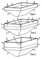
- Fig.1 shows a perspective view of an examplary hopper without extension walls;
- Fig.2 shows the hopper of fig.1 with extension walls;
- Fig.3 shows the hopper of fig. 1 with different extension walls;
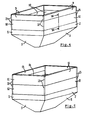
- Fig.4 shows the hopper of fig.1 with yet different extension walls;
- Fig.5 shows the hopper of fig.1 with still different extension walls;
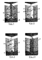
- Fig.6 shows a section according to VI-VI in fig.4 on a larger scale;
- Fig.7-10 show succesive stages while mounting extension walls, and
- Fig.11 shows perspectively and from the rear side a cover.
- Firstly referring to fig.1, an example of a hopper according to the invention (however prior to the application of the extension walls) is illustrated in a perspective view. In the illustrated embodiment the hopper basically comprises four side walls 1-4 connected at their lower ends to
respective bottom walls 5. The lowermost part of said bottom walls can have a specific shape and could comprise specific arrangements (such as, for example, for distributing seeds or fertilizer on a field) which, however, fall beyond the scope of the invention and thus will not be specified further within the context of this description. Each side wall 1-4 is at its top provided with anedge section 6 extending inclined inwardly and upwardly. - In fig.2
extension walls 7 having a first height have been positioned on top of the respective side walls 1-4. The manner of positioning saidextension walls 7 and maintaining these in such a position will be elucidated further below. - In fig.3
extension walls 8 having a second, greater height have been positioned on top of the respective side walls 1-4. Again, the manner of positioning saidextension walls 8 and maintaining these in such a position will be elucidated further below. - In fig.4 a double layer of
extension walls - In fig.5 a configuration of the hopper is illustrated, in which on three sides a double layer of
extension walls extension walls 13 and 14 are visible) has been positioned. - From fig.2-5 it appears, that the present invention allows many combinations of extension walls to be provided on top of the side walls 1-4. Although not shown here, it is also possible that on top of some of the side walls 1-4 none such extension walls are provided.
- The manner in which the extension walls are positioned on top of the respective side walls (or on top of preceding extension walls, whatever the case may be) now will be explained while referring to fig.6-10.
- Fig.6 illustrates a cross-section according to VI-VI in fig.4. Part of
side wall 2,extension wall 10 and part ofextension wall 9 are visible. Theextension wall 10 at its lower end is provided with arecess 15 for receiving theedge section 6 of theside wall 2. Likewise, the top of theextension wall 10 is provided with anedge section 16 that is received in a recess provided at the lower end of theextension wall 9. - It is noted that in the embodiments illustrated in fig.2 and fig.3 the
extension walls - The cooperation between the edge sections 6 (16) and recesses 15 (17) is such that the extension walls 10 (9) are maintained in their position under the influence of gravity. In this position the outer surfaces of the
side wall 2 andextension walls 10 and 9 (shown at the right-hand side) lie flush. Positioning an extension wall on top of a side wall can be accomplished without any specialised tools and can be carried out by a single person. - Fig.6 shows clearly that, for example, the
extension walls 10 are extrusion profiles (for example made of aluminum) provided with twoholes 18 which, for reasons to be explained further below, are threaded. - Fig.7 shows a corner region where two
extension walls 7 meet. Theextension walls 7 are positioned on top of theside walls - Fig.8 shows the same corner region, however after positioning an angled plate 19 having two
wings 20. Saidwings 20 are provided withholes 21 which coincide with the threadedholes 18 in the extension walls 7 (see fig.7). The contour of thewings 20 substantially corresponds with the profile of the extension walls 7 (or, at least, does not project therebeyond). - In fig.9
bolts 22 are introduced into theholes 21 in thewings 20 of the angled plate 19 and threadably secured into the threadedholes 18 of the extension walls. As a result theextension walls 7 are now firmly interconnected through the angled plate 19, thus making removal of theextension walls 7 from therespective side walls bolts 22. - It is noted that also other ways of interconnecting adjacent extension walls are conceivable. For example, the angled plate (or a corresponding member) could be integrated with one of the extension walls, such that only bolts should be used at one side in said corner region.
- Fig. 10 shows the same corner region of the hopper after application of a
cover 23. Said cover is also illustrated in fig. 11 in a view from behind. As illustrated, it comprises recesses ordepressions 24 which will snappingly cooperate with the heads of thebolts 22 for keeping the cover in its position. The outer surface of thecover 23 lies flush with the outer surface of the adjoiningextension walls 7 and could be provided with depressions (indicated indotted lines 24 in fig.23) for receiving reflector means, information sheets or alike. - The invention is not limited to the embodiments described before which may be varied widely within the scope of the invention as defined by the appending claims.
Claims (19)
characterized in that
wall extensions are positioned on top of the side walls of at least one pair of adjacent side walls, which wall extensions at their lower end each are provided with recesses for matingly receiving the inclined edge sections of the corresponding side walls, and wherein said wall extensions are interconnected by connecting means.
Priority Applications (3)
| Application Number | Priority Date | Filing Date | Title |
|---|---|---|---|
| DK06110027.7T DK1820383T3 (en) | 2006-02-16 | 2006-02-16 | Tunnel container with side elevations |
| ES06110027.7T ES2643616T3 (en) | 2006-02-16 | 2006-02-16 | Hopper with wall extensions |
| EP06110027.7A EP1820383B1 (en) | 2006-02-16 | 2006-02-16 | Hopper with wall extensions |
Applications Claiming Priority (1)
| Application Number | Priority Date | Filing Date | Title |
|---|---|---|---|
| EP06110027.7A EP1820383B1 (en) | 2006-02-16 | 2006-02-16 | Hopper with wall extensions |
Publications (2)
| Publication Number | Publication Date |
|---|---|
| EP1820383A1 true EP1820383A1 (en) | 2007-08-22 |
| EP1820383B1 EP1820383B1 (en) | 2017-07-19 |
Family
ID=36070243
Family Applications (1)
| Application Number | Title | Priority Date | Filing Date |
|---|---|---|---|
| EP06110027.7A Expired - Lifetime EP1820383B1 (en) | 2006-02-16 | 2006-02-16 | Hopper with wall extensions |
Country Status (3)
| Country | Link |
|---|---|
| EP (1) | EP1820383B1 (en) |
| DK (1) | DK1820383T3 (en) |
| ES (1) | ES2643616T3 (en) |
Cited By (5)
| Publication number | Priority date | Publication date | Assignee | Title |
|---|---|---|---|---|
| WO2012007532A1 (en) * | 2010-07-13 | 2012-01-19 | Cnh Belgium N.V. | Grain tank cover for a combine harvester |
| WO2022195471A1 (en) * | 2021-03-17 | 2022-09-22 | Maschio Gaspardo S.P.A. | Raised wall for hoppers, in particular for fertilizer spreading machines and hopper obtained in this manner |
| WO2025016648A1 (en) * | 2023-07-18 | 2025-01-23 | Amazonen-Werke H. Dreyer SE & Co. KG | Spreader for applying spreading material |
| RU2852767C1 (en) * | 2021-03-17 | 2025-12-15 | Маскио Гаспардо С.П.А. | Raised wall for bins, particularly for fertiliser spreader machines, and bin thus obtained |
| DE102025100958A1 (en) * | 2025-01-13 | 2026-07-16 | Kverneland Group Nieuw-Vennep B.V. | Storage container for a distribution machine and distribution machine for dispensing a granular material |
Citations (4)
| Publication number | Priority date | Publication date | Assignee | Title |
|---|---|---|---|---|
| US4460214A (en) * | 1982-03-03 | 1984-07-17 | E-Z Trail, Inc. | Vehicle side extension |
| DE4405479A1 (en) * | 1994-02-21 | 1995-08-24 | Amazonen Werke Dreyer H | Assembly system of prefabricated machine parts for pneumatic drill |
| EP0982191A1 (en) * | 1998-08-26 | 2000-03-01 | Maasland N.V. | An implement for spreading material |
| DE10359179A1 (en) * | 2003-12-17 | 2005-07-21 | Amazonen-Werke H. Dreyer Gmbh & Co. Kg | Container element for parts for putting on agricultural distribution machines to enlarge their capacity consists of plastic oblong sides joined together by corner pieces |
-
2006
- 2006-02-16 ES ES06110027.7T patent/ES2643616T3/en not_active Expired - Lifetime
- 2006-02-16 EP EP06110027.7A patent/EP1820383B1/en not_active Expired - Lifetime
- 2006-02-16 DK DK06110027.7T patent/DK1820383T3/en active
Patent Citations (4)
| Publication number | Priority date | Publication date | Assignee | Title |
|---|---|---|---|---|
| US4460214A (en) * | 1982-03-03 | 1984-07-17 | E-Z Trail, Inc. | Vehicle side extension |
| DE4405479A1 (en) * | 1994-02-21 | 1995-08-24 | Amazonen Werke Dreyer H | Assembly system of prefabricated machine parts for pneumatic drill |
| EP0982191A1 (en) * | 1998-08-26 | 2000-03-01 | Maasland N.V. | An implement for spreading material |
| DE10359179A1 (en) * | 2003-12-17 | 2005-07-21 | Amazonen-Werke H. Dreyer Gmbh & Co. Kg | Container element for parts for putting on agricultural distribution machines to enlarge their capacity consists of plastic oblong sides joined together by corner pieces |
Cited By (8)
| Publication number | Priority date | Publication date | Assignee | Title |
|---|---|---|---|---|
| WO2012007532A1 (en) * | 2010-07-13 | 2012-01-19 | Cnh Belgium N.V. | Grain tank cover for a combine harvester |
| BE1019421A3 (en) * | 2010-07-13 | 2012-07-03 | Cnh Belgium Nv | CEREAL TANK COVER FOR A CUTTER. |
| WO2022195471A1 (en) * | 2021-03-17 | 2022-09-22 | Maschio Gaspardo S.P.A. | Raised wall for hoppers, in particular for fertilizer spreading machines and hopper obtained in this manner |
| CN117337131A (en) * | 2021-03-17 | 2024-01-02 | 马斯奇奥盖斯帕多股份有限公司 | Raised walls for hoppers, in particular for fertilizer spreaders, and hoppers obtained in this way |
| US20240155968A1 (en) * | 2021-03-17 | 2024-05-16 | Maschio Gaspardo S.P.A. | Raised wall for hoppers, in particular for fertilizer spreading machines and hopper obtained in this matter |
| RU2852767C1 (en) * | 2021-03-17 | 2025-12-15 | Маскио Гаспардо С.П.А. | Raised wall for bins, particularly for fertiliser spreader machines, and bin thus obtained |
| WO2025016648A1 (en) * | 2023-07-18 | 2025-01-23 | Amazonen-Werke H. Dreyer SE & Co. KG | Spreader for applying spreading material |
| DE102025100958A1 (en) * | 2025-01-13 | 2026-07-16 | Kverneland Group Nieuw-Vennep B.V. | Storage container for a distribution machine and distribution machine for dispensing a granular material |
Also Published As
| Publication number | Publication date |
|---|---|
| DK1820383T3 (en) | 2017-10-23 |
| EP1820383B1 (en) | 2017-07-19 |
| ES2643616T3 (en) | 2017-11-23 |
Similar Documents
| Publication | Publication Date | Title |
|---|---|---|
| USD481044S1 (en) | Mini-excavator cab exterior | |
| USD576183S1 (en) | Tooth assembly for buckets | |
| US7270307B2 (en) | Ladder accessory assembly | |
| CA2387115C (en) | Landscape edging system with stakes attached | |
| US20100218432A1 (en) | Adjustable wall system | |
| CA2574587A1 (en) | Snow pusher | |
| US20010045030A1 (en) | Rake attachment for skid steer loaders and front end loaders and method for converting a loader bucket into a lawn preparation tool | |
| US7343864B2 (en) | Modular worktable and shelving unit | |
| US5603549A (en) | Nestable multipiece truck cab roof fairing assembly | |
| EP1820383B1 (en) | Hopper with wall extensions | |
| US20180125232A1 (en) | Shelving assembly and method of assembly | |
| CA2452086A1 (en) | Mud flap hanger system | |
| CN110121582A (en) | Plank Connector | |
| CN102124167B (en) | wear parts | |
| USD933328S1 (en) | Paint station | |
| WO2015124307A1 (en) | Vertical garden system and planting trough | |
| GB2467443A (en) | Cable tray bridge for joining trays or ducts | |
| US11291904B2 (en) | Portable pitching mound | |
| US5669760A (en) | Ceiling fan with integral blade and neck | |
| FR2789862A3 (en) | WALL STRUCTURE HAVING AN INSERTED PROFILE TRACK FOR HANGING SUPPORT ARMS FOR DIRECT OR INDIRECT SUSPENSION OF ARTICLES | |
| US12601129B2 (en) | Snowplow blade edge shoe and methods of use | |
| US9845613B1 (en) | Sidewall attachment system | |
| US20080110087A1 (en) | Wall flower pot mount and post flower pot | |
| USD511207S1 (en) | Combination ceiling fan and light fixture | |
| JP3440445B2 (en) | Mounting structure of reinforcement material for soundproof panel |
Legal Events
| Date | Code | Title | Description |
|---|---|---|---|
| PUAI | Public reference made under article 153(3) epc to a published international application that has entered the european phase |
Free format text: ORIGINAL CODE: 0009012 |
|
| AK | Designated contracting states |
Kind code of ref document: A1 Designated state(s): AT BE BG CH CY CZ DE DK EE ES FI FR GB GR HU IE IS IT LI LT LU LV MC NL PL PT RO SE SI SK TR |
|
| AX | Request for extension of the european patent |
Extension state: AL BA HR MK YU |
|
| 17P | Request for examination filed |
Effective date: 20080207 |
|
| 17Q | First examination report despatched |
Effective date: 20080326 |
|
| AKX | Designation fees paid |
Designated state(s): AT BE BG CH CY CZ DE DK EE ES FI FR GB GR HU IE IS IT LI LT LU LV MC NL PL PT RO SE SI SK TR |
|
| GRAP | Despatch of communication of intention to grant a patent |
Free format text: ORIGINAL CODE: EPIDOSNIGR1 |
|
| INTG | Intention to grant announced |
Effective date: 20170421 |
|
| GRAS | Grant fee paid |
Free format text: ORIGINAL CODE: EPIDOSNIGR3 |
|
| GRAA | (expected) grant |
Free format text: ORIGINAL CODE: 0009210 |
|
| AK | Designated contracting states |
Kind code of ref document: B1 Designated state(s): AT BE BG CH CY CZ DE DK EE ES FI FR GB GR HU IE IS IT LI LT LU LV MC NL PL PT RO SE SI SK TR |
|
| REG | Reference to a national code |
Ref country code: GB Ref legal event code: FG4D |
|
| REG | Reference to a national code |
Ref country code: CH Ref legal event code: EP |
|
| REG | Reference to a national code |
Ref country code: IE Ref legal event code: FG4D |
|
| REG | Reference to a national code |
Ref country code: AT Ref legal event code: REF Ref document number: 909448 Country of ref document: AT Kind code of ref document: T Effective date: 20170815 |
|
| REG | Reference to a national code |
Ref country code: DE Ref legal event code: R096 Ref document number: 602006053044 Country of ref document: DE |
|
| REG | Reference to a national code |
Ref country code: NL Ref legal event code: FP |
|
| REG | Reference to a national code |
Ref country code: DK Ref legal event code: T3 Effective date: 20171018 |
|
| REG | Reference to a national code |
Ref country code: ES Ref legal event code: FG2A Ref document number: 2643616 Country of ref document: ES Kind code of ref document: T3 Effective date: 20171123 |
|
| REG | Reference to a national code |
Ref country code: LT Ref legal event code: MG4D |
|
| REG | Reference to a national code |
Ref country code: AT Ref legal event code: MK05 Ref document number: 909448 Country of ref document: AT Kind code of ref document: T Effective date: 20170719 |
|
| PG25 | Lapsed in a contracting state [announced via postgrant information from national office to epo] |
Ref country code: FI Free format text: LAPSE BECAUSE OF FAILURE TO SUBMIT A TRANSLATION OF THE DESCRIPTION OR TO PAY THE FEE WITHIN THE PRESCRIBED TIME-LIMIT Effective date: 20170719 Ref country code: LT Free format text: LAPSE BECAUSE OF FAILURE TO SUBMIT A TRANSLATION OF THE DESCRIPTION OR TO PAY THE FEE WITHIN THE PRESCRIBED TIME-LIMIT Effective date: 20170719 Ref country code: AT Free format text: LAPSE BECAUSE OF FAILURE TO SUBMIT A TRANSLATION OF THE DESCRIPTION OR TO PAY THE FEE WITHIN THE PRESCRIBED TIME-LIMIT Effective date: 20170719 Ref country code: SE Free format text: LAPSE BECAUSE OF FAILURE TO SUBMIT A TRANSLATION OF THE DESCRIPTION OR TO PAY THE FEE WITHIN THE PRESCRIBED TIME-LIMIT Effective date: 20170719 |
|
| REG | Reference to a national code |
Ref country code: FR Ref legal event code: PLFP Year of fee payment: 13 |
|
| PG25 | Lapsed in a contracting state [announced via postgrant information from national office to epo] |
Ref country code: BG Free format text: LAPSE BECAUSE OF FAILURE TO SUBMIT A TRANSLATION OF THE DESCRIPTION OR TO PAY THE FEE WITHIN THE PRESCRIBED TIME-LIMIT Effective date: 20171019 Ref country code: PL Free format text: LAPSE BECAUSE OF FAILURE TO SUBMIT A TRANSLATION OF THE DESCRIPTION OR TO PAY THE FEE WITHIN THE PRESCRIBED TIME-LIMIT Effective date: 20170719 Ref country code: IS Free format text: LAPSE BECAUSE OF FAILURE TO SUBMIT A TRANSLATION OF THE DESCRIPTION OR TO PAY THE FEE WITHIN THE PRESCRIBED TIME-LIMIT Effective date: 20171119 Ref country code: GR Free format text: LAPSE BECAUSE OF FAILURE TO SUBMIT A TRANSLATION OF THE DESCRIPTION OR TO PAY THE FEE WITHIN THE PRESCRIBED TIME-LIMIT Effective date: 20171020 Ref country code: LV Free format text: LAPSE BECAUSE OF FAILURE TO SUBMIT A TRANSLATION OF THE DESCRIPTION OR TO PAY THE FEE WITHIN THE PRESCRIBED TIME-LIMIT Effective date: 20170719 |
|
| REG | Reference to a national code |
Ref country code: DE Ref legal event code: R097 Ref document number: 602006053044 Country of ref document: DE |
|
| PG25 | Lapsed in a contracting state [announced via postgrant information from national office to epo] |
Ref country code: CZ Free format text: LAPSE BECAUSE OF FAILURE TO SUBMIT A TRANSLATION OF THE DESCRIPTION OR TO PAY THE FEE WITHIN THE PRESCRIBED TIME-LIMIT Effective date: 20170719 Ref country code: RO Free format text: LAPSE BECAUSE OF FAILURE TO SUBMIT A TRANSLATION OF THE DESCRIPTION OR TO PAY THE FEE WITHIN THE PRESCRIBED TIME-LIMIT Effective date: 20170719 |
|
| PLBE | No opposition filed within time limit |
Free format text: ORIGINAL CODE: 0009261 |
|
| STAA | Information on the status of an ep patent application or granted ep patent |
Free format text: STATUS: NO OPPOSITION FILED WITHIN TIME LIMIT |
|
| PG25 | Lapsed in a contracting state [announced via postgrant information from national office to epo] |
Ref country code: SK Free format text: LAPSE BECAUSE OF FAILURE TO SUBMIT A TRANSLATION OF THE DESCRIPTION OR TO PAY THE FEE WITHIN THE PRESCRIBED TIME-LIMIT Effective date: 20170719 Ref country code: EE Free format text: LAPSE BECAUSE OF FAILURE TO SUBMIT A TRANSLATION OF THE DESCRIPTION OR TO PAY THE FEE WITHIN THE PRESCRIBED TIME-LIMIT Effective date: 20170719 |
|
| 26N | No opposition filed |
Effective date: 20180420 |
|
| PG25 | Lapsed in a contracting state [announced via postgrant information from national office to epo] |
Ref country code: SI Free format text: LAPSE BECAUSE OF FAILURE TO SUBMIT A TRANSLATION OF THE DESCRIPTION OR TO PAY THE FEE WITHIN THE PRESCRIBED TIME-LIMIT Effective date: 20170719 |
|
| REG | Reference to a national code |
Ref country code: CH Ref legal event code: PL |
|
| PG25 | Lapsed in a contracting state [announced via postgrant information from national office to epo] |
Ref country code: MC Free format text: LAPSE BECAUSE OF FAILURE TO SUBMIT A TRANSLATION OF THE DESCRIPTION OR TO PAY THE FEE WITHIN THE PRESCRIBED TIME-LIMIT Effective date: 20170719 |
|
| GBPC | Gb: european patent ceased through non-payment of renewal fee |
Effective date: 20180216 |
|
| REG | Reference to a national code |
Ref country code: IE Ref legal event code: MM4A |
|
| REG | Reference to a national code |
Ref country code: BE Ref legal event code: MM Effective date: 20180228 |
|
| PG25 | Lapsed in a contracting state [announced via postgrant information from national office to epo] |
Ref country code: LI Free format text: LAPSE BECAUSE OF NON-PAYMENT OF DUE FEES Effective date: 20180228 Ref country code: CH Free format text: LAPSE BECAUSE OF NON-PAYMENT OF DUE FEES Effective date: 20180228 Ref country code: LU Free format text: LAPSE BECAUSE OF NON-PAYMENT OF DUE FEES Effective date: 20180216 |
|
| PG25 | Lapsed in a contracting state [announced via postgrant information from national office to epo] |
Ref country code: IE Free format text: LAPSE BECAUSE OF NON-PAYMENT OF DUE FEES Effective date: 20180216 |
|
| PG25 | Lapsed in a contracting state [announced via postgrant information from national office to epo] |
Ref country code: GB Free format text: LAPSE BECAUSE OF NON-PAYMENT OF DUE FEES Effective date: 20180216 Ref country code: BE Free format text: LAPSE BECAUSE OF NON-PAYMENT OF DUE FEES Effective date: 20180228 |
|
| PG25 | Lapsed in a contracting state [announced via postgrant information from national office to epo] |
Ref country code: TR Free format text: LAPSE BECAUSE OF FAILURE TO SUBMIT A TRANSLATION OF THE DESCRIPTION OR TO PAY THE FEE WITHIN THE PRESCRIBED TIME-LIMIT Effective date: 20170719 |
|
| PG25 | Lapsed in a contracting state [announced via postgrant information from national office to epo] |
Ref country code: PT Free format text: LAPSE BECAUSE OF FAILURE TO SUBMIT A TRANSLATION OF THE DESCRIPTION OR TO PAY THE FEE WITHIN THE PRESCRIBED TIME-LIMIT Effective date: 20170719 Ref country code: HU Free format text: LAPSE BECAUSE OF FAILURE TO SUBMIT A TRANSLATION OF THE DESCRIPTION OR TO PAY THE FEE WITHIN THE PRESCRIBED TIME-LIMIT; INVALID AB INITIO Effective date: 20060216 |
|
| PG25 | Lapsed in a contracting state [announced via postgrant information from national office to epo] |
Ref country code: CY Free format text: LAPSE BECAUSE OF FAILURE TO SUBMIT A TRANSLATION OF THE DESCRIPTION OR TO PAY THE FEE WITHIN THE PRESCRIBED TIME-LIMIT Effective date: 20170719 |
|
| P01 | Opt-out of the competence of the unified patent court (upc) registered |
Effective date: 20230525 |
|
| PGFP | Annual fee paid to national office [announced via postgrant information from national office to epo] |
Ref country code: NL Payment date: 20250218 Year of fee payment: 20 |
|
| PGFP | Annual fee paid to national office [announced via postgrant information from national office to epo] |
Ref country code: DE Payment date: 20250218 Year of fee payment: 20 |
|
| PGFP | Annual fee paid to national office [announced via postgrant information from national office to epo] |
Ref country code: DK Payment date: 20250224 Year of fee payment: 20 |
|
| PGFP | Annual fee paid to national office [announced via postgrant information from national office to epo] |
Ref country code: ES Payment date: 20250328 Year of fee payment: 20 |
|
| PGFP | Annual fee paid to national office [announced via postgrant information from national office to epo] |
Ref country code: FR Payment date: 20250221 Year of fee payment: 20 |
|
| PGFP | Annual fee paid to national office [announced via postgrant information from national office to epo] |
Ref country code: IT Payment date: 20250224 Year of fee payment: 20 |
|
| REG | Reference to a national code |
Ref country code: DE Ref legal event code: R071 Ref document number: 602006053044 Country of ref document: DE |
|
| REG | Reference to a national code |
Ref country code: NL Ref legal event code: MK Effective date: 20260215 |
|
| REG | Reference to a national code |
Ref country code: DK Ref legal event code: EUP Expiry date: 20260216 |
|
| REG | Reference to a national code |
Ref country code: ES Ref legal event code: FD2A Effective date: 20260227 |
|
| PG25 | Lapsed in a contracting state [announced via postgrant information from national office to epo] |
Ref country code: ES Free format text: LAPSE BECAUSE OF EXPIRATION OF PROTECTION Effective date: 20260217 |