EP1819582B1 - Eccentric wheel apparatus for rocking bicycle - Google Patents
Eccentric wheel apparatus for rocking bicycle Download PDFInfo
- Publication number
- EP1819582B1 EP1819582B1 EP05825794A EP05825794A EP1819582B1 EP 1819582 B1 EP1819582 B1 EP 1819582B1 EP 05825794 A EP05825794 A EP 05825794A EP 05825794 A EP05825794 A EP 05825794A EP 1819582 B1 EP1819582 B1 EP 1819582B1
- Authority
- EP
- European Patent Office
- Prior art keywords
- wheel
- frame
- rotating frame
- unevenness
- circumferential portion
- Prior art date
- Legal status (The legal status is an assumption and is not a legal conclusion. Google has not performed a legal analysis and makes no representation as to the accuracy of the status listed.)
- Ceased
Links
Images






Classifications
-
- B—PERFORMING OPERATIONS; TRANSPORTING
- B62—LAND VEHICLES FOR TRAVELLING OTHERWISE THAN ON RAILS
- B62M—RIDER PROPULSION OF WHEELED VEHICLES OR SLEDGES; POWERED PROPULSION OF SLEDGES OR SINGLE-TRACK CYCLES; TRANSMISSIONS SPECIALLY ADAPTED FOR SUCH VEHICLES
- B62M3/00—Construction of cranks operated by hand or foot
- B62M3/06—Construction of cranks operated by hand or foot with elliptical or other non-circular rotary movement
-
- B—PERFORMING OPERATIONS; TRANSPORTING
- B60—VEHICLES IN GENERAL
- B60B—VEHICLE WHEELS; CASTORS; AXLES FOR WHEELS OR CASTORS; INCREASING WHEEL ADHESION
- B60B27/00—Hubs
- B60B27/02—Hubs adapted to be rotatably arranged on axle
- B60B27/04—Hubs adapted to be rotatably arranged on axle housing driving means, e.g. sprockets
-
- B—PERFORMING OPERATIONS; TRANSPORTING
- B60—VEHICLES IN GENERAL
- B60B—VEHICLE WHEELS; CASTORS; AXLES FOR WHEELS OR CASTORS; INCREASING WHEEL ADHESION
- B60B27/00—Hubs
- B60B27/02—Hubs adapted to be rotatably arranged on axle
- B60B27/023—Hubs adapted to be rotatably arranged on axle specially adapted for bicycles
-
- B—PERFORMING OPERATIONS; TRANSPORTING
- B60—VEHICLES IN GENERAL
- B60B—VEHICLE WHEELS; CASTORS; AXLES FOR WHEELS OR CASTORS; INCREASING WHEEL ADHESION
- B60B27/00—Hubs
- B60B27/02—Hubs adapted to be rotatably arranged on axle
- B60B27/04—Hubs adapted to be rotatably arranged on axle housing driving means, e.g. sprockets
- B60B27/047—Hubs adapted to be rotatably arranged on axle housing driving means, e.g. sprockets comprising a freewheel mechanisms
-
- B—PERFORMING OPERATIONS; TRANSPORTING
- B62—LAND VEHICLES FOR TRAVELLING OTHERWISE THAN ON RAILS
- B62K—CYCLES; CYCLE FRAMES; CYCLE STEERING DEVICES; RIDER-OPERATED TERMINAL CONTROLS SPECIALLY ADAPTED FOR CYCLES; CYCLE AXLE SUSPENSIONS; CYCLE SIDECARS, FORECARS, OR THE LIKE
- B62K17/00—Cycles not otherwise provided for
-
- B—PERFORMING OPERATIONS; TRANSPORTING
- B62—LAND VEHICLES FOR TRAVELLING OTHERWISE THAN ON RAILS
- B62K—CYCLES; CYCLE FRAMES; CYCLE STEERING DEVICES; RIDER-OPERATED TERMINAL CONTROLS SPECIALLY ADAPTED FOR CYCLES; CYCLE AXLE SUSPENSIONS; CYCLE SIDECARS, FORECARS, OR THE LIKE
- B62K25/00—Axle suspensions
-
- B—PERFORMING OPERATIONS; TRANSPORTING
- B62—LAND VEHICLES FOR TRAVELLING OTHERWISE THAN ON RAILS
- B62M—RIDER PROPULSION OF WHEELED VEHICLES OR SLEDGES; POWERED PROPULSION OF SLEDGES OR SINGLE-TRACK CYCLES; TRANSMISSIONS SPECIALLY ADAPTED FOR SUCH VEHICLES
- B62M3/00—Construction of cranks operated by hand or foot
-
- B—PERFORMING OPERATIONS; TRANSPORTING
- B60—VEHICLES IN GENERAL
- B60B—VEHICLE WHEELS; CASTORS; AXLES FOR WHEELS OR CASTORS; INCREASING WHEEL ADHESION
- B60B2900/00—Purpose of invention
- B60B2900/90—Providing or changing
- B60B2900/911—Eccentricity
-
- Y—GENERAL TAGGING OF NEW TECHNOLOGICAL DEVELOPMENTS; GENERAL TAGGING OF CROSS-SECTIONAL TECHNOLOGIES SPANNING OVER SEVERAL SECTIONS OF THE IPC; TECHNICAL SUBJECTS COVERED BY FORMER USPC CROSS-REFERENCE ART COLLECTIONS [XRACs] AND DIGESTS
- Y10—TECHNICAL SUBJECTS COVERED BY FORMER USPC
- Y10T—TECHNICAL SUBJECTS COVERED BY FORMER US CLASSIFICATION
- Y10T74/00—Machine element or mechanism
- Y10T74/15—Intermittent grip type mechanical movement
- Y10T74/1503—Rotary to intermittent unidirectional motion
- Y10T74/1508—Rotary crank or eccentric drive
- Y10T74/151—Adjustable
Definitions
- the present invention relates to an eccentric wheel apparatus for a rocking bicycle in which the axis of the eccentric wheel apparatus is eccentrical with the central driving shaft thereof and thus the shaft is shaken up and down during running of the wheel, and more particularly, to an eccentric wheel apparatus for a rocking bicycle which can be employed in a general bicycle by adjusting a shaking degree, and of which shaking width of a variety of eccentric angles can be adjusted.
- FIG. 1 is a side view showing an example of a conventional rocking bicycle, which is disclosed in a Korean Utility Model Registration Publication No. 183508 ( KR 200183508Y ) in the name of the same applicant as that of this invention.
- An intermediate wheel 40 is connected with a right-hand wheel 20 and a left-hand wheel 30 by means of a bolt 11.
- a number of chain sprockets 12 whose teeth become small sequentially from the concentrical axis with respect to a center 5a which is congruent with the center of a joint shaft 5 are connected with the outer surface of the right-hand wheel 20 located at a position of the center 5a.
- a shaft hole 12a whose center is congruent with the center 5a is formed on the center of the chain sprockets 12.
- An inner circumferential portion 21 having a certain height is protrudingly installed in the inner side of the right-hand wheel 20.
- a spur gear 22 having a certain pitch and a certain number of teeth is formed along the inner circumferential portion 21 in the inner side of the inner circumferential portion 21.
- a screw coupling unit 24 whose an inner side is formed of a female screw 23 is protrudingly installed at a certain position of the inner side surface of the right-hand wheel 20.
- a spring 25 giving an elastic force is wound around the outer circumferential portion of the screw coupling unit 24.
- the left-hand wheel 30 which is engaged with the screw coupling unit 24 protruded in the right-hand wheel 20 by means of a bolt 11 also includes a spur gear 22a having the same pitch and teeth as those of the spur gear 22 formed in the right-hand wheel 20 which is formed along an inner circumferential portion 31 in the inner side of the inner circumferential portion 31 of the left-hand wheel 30 in correspondence to the spur gear 22.
- the joint shaft 5 is inserted into the shaft hole 12a of the chain sprocket 12 formed in the right-hand wheel 20.
- the intermediate wheel 40 is installed between the right-hand wheel 20 and the left-hand wheel 30 to make the right-hand wheel 20 and the left-hand wheel 30 coupled with or separated from each other.
- a number of small or large spokes 3 are integrally installed in an outer circumferential portion 41 of the intermediate wheel 40.
- a spur gear 22b and a spur gear 22c which have the same tooth-shapes as those of the spur gears 22 and 22a are formed in the inner side of the outer circumferential portion 41 in correspondence to each other, in a manner that the spur gear 22 and the spur gear 22a which are formed in the right-hand wheel 20 and the left-hand wheel 30, respectively, can be engaged with each other. Accordingly, the spur gears 22, 22a, 22b, and 22c can be engaged with one another.
- the bolt 11 in the left-hand wheel 30 is screw-connected with the screw coupling unit 24 in the right-hand wheel 20.
- Bearings 6 and 6a are installed at the left and right ends of the joint shaft 5, respectively. Accordingly, the front drive wheel 10 in which the right-hand wheel 20, the intermediate wheel 40 and the left-hand wheel 30 are coupled with one another can be smoothly rotated according to rotation of the chain sprockets 12.
- a rear frame 4 is axially installed and screw-connected with nuts (not shown).
- the conventional rocking bicycle having an eccentric wheel apparatus includes the right-hand wheel 20 and the left-hand wheel 30 which are engaged with the intermediate wheel 40 by means of the spur gears 22, 22a, 22b, and 22c to play a role of the front drive wheel 10, and assembled with one another by means of the bolt 11 and the screw coupling unit 24. Accordingly, since the right-hand wheel 20 and the left-hand wheel 30 should be engaged with each other centering on the intermediate wheel 40, a strong engagement force should be required for the right-hand wheel 20, the left-hand wheel 30, and the intermediate wheel 40.
- the tightening length of the bolt 11 is limited since the bolt 11 should be positioned at the inner side of a brake in view of the structures in thickness of the wheels, and thus the trifold engagement structure among the right-hand wheel 20, the left-hand wheel 30, and the intermediate wheel 40 cannot be firmly tightened. As a result, the trifold engagement structure may be released during running.
- the spur gears 22, 22a, 22b, and 22c should be formed in the left-hand wheel 30, the inner side of the right-hand wheel 20, and both sides of the intermediate wheel 40, which pushes a production cost to rise.
- the assembly bolt 11 which assembles the left-hand wheel 30, the right-hand wheel 20, and the intermediate wheel 40 is small-sized, it may be released or lost. In this case, since the trifold engagement structure is broken, the wheels may be separated during running to thereby cause danger.
- an object of the present invention to provide an eccentric wheel apparatus for a rocking bicycle which employs an engagement structure of the eccentric wheel apparatus so as to be firmly assembled not by a conventional trifold engagement structure but by a new adjustment structure.
- an eccentric wheel apparatus for a rocking bicycle according to claim 1.
- the eccentric wheel apparatus includes a ratchet which is elastically supported by a torsion spring at a predetermined position of the wheel frame and forms a contact, and a ratchet gear formed in the extension portion of the adjustment member so as to elastically abut the contact.
- the eccentric wheel apparatus includes elastic insertion holes formed from the outer side of the extension portion in the rotating frame to the inner side thereof, a coil spring, a contact ball and a bolt which are internally fixed in the elastic insertion holes, and elastic insertion grooves which slidingly contact the insertion support portion at the ends of the elastic insertion holes in which contact balls are mounted.
- the eccentric wheel apparatus further includes a cover member instead of a bolt for supporting the coil spring to be inserted into an elastic hole.
- a cover member instead of a bolt for supporting the coil spring to be inserted into an elastic hole.
- the present invention provides an eccentric wheel apparatus for a rocking bicycle according to the present invention has improved problems having occurred in the conventional eccentric wheel apparatus in which tooth-engagement is stably achieved when a rotating frame and a wheel frame which are integrally combined with a driving shaft are eccentrically adjusted, and angular adjustment is simply achieved. Also, the eccentric wheel apparatus according to the present invention maximizes a tooth-engagement capability corresponding to running of a bicycle, as well as a tightening capability, to thereby heighten utility.
- the eccentric wheel apparatus prevents release or secession, to thereby prevent an accident which can take place when an engagement state is released or seceded during running of a bicycle.
- FIG. 1 is a side view showing an example of a conventional rocking bicycle
- FIG. 2 is an exploded view showing a conventional eccentric wheel apparatus for a rocking bicycle
- FIG. 3 is a cross-sectional view showing a conventional eccentric wheel apparatus for a rocking bicycle
- FIG. 4 is an enlarged perspective view of a rear wheel in which an eccentric wheel apparatus for a rocking bicycle according to a first embodiment of the present invention is employed;
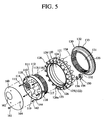
- FIG. 5 is an exploded perspective view showing an eccentric wheel apparatus for a rocking bicycle according to a first embodiment of the present invention
- FIGs. 6 and 7 are longitudinal cross-sectional views showing functions of the eccentric wheel apparatus for a rocking bicycle according to the first embodiment of the present invention, respectively;
- FIG. 8 is an exploded perspective view showing an eccentric wheel apparatus for a rocking bicycle according to a second embodiment of the present invention.
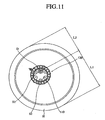
- FIGs. 9 through 12 are front views for explaining an up-movement or a down-movement of a rear wheel according to an eccentric position of each embodiment of the eccentric wheel apparatus for a rocking bicycle according to the present invention
- FIG. 13 is an exploded perspective view showing an eccentric wheel apparatus for a rocking bicycle according to a third embodiment of the present invention.
- FIG. 14 is a cross-sectional view for explaining functions of the eccentric wheel apparatus for a rocking bicycle according to the third embodiment of the present invention.
- FIG. 4 is an enlarged perspective view of a rear wheel in which an eccentric wheel apparatus for a rocking bicycle according to a first embodiment of the present invention is employed
- FIG. 5 is an exploded perspective view showing an eccentric wheel apparatus for a rocking bicycle according to a first embodiment of the present invention.
- the eccentric wheel apparatus for a rocking bicycle includes a rotating frame 110 in which a driving shaft D is installed, a wheel frame 120, and a circular adjustment member 130 which couples and adjusts the rotating frame 110 and the wheel frame 120.
- the eccentric wheel apparatus for a rocking bicycle according to the present invention will be described with respect to a case applied to a rear wheel.
- the eccentric wheel apparatus according to the present invention can be applied to a front wheel.
- the eccentric wheel apparatus according to the present invention can be applied to an indoor exercise bicycle-related training facility as well as a general bicycle.
- an eccentric wheel apparatus which is applied to a rear wheel for a bicycle will be described.
- a rotating frame 110 of a cylindrical body includes an isolation plate 119 by which the left and right sides of the inner portion thereof are isolated.
- An axial tube 115 having a throughhole 114 to which the driving shaft D is penetratively fixed on a screw connection basis is eccentrically formed via the isolation plate 119.
- a spiral 116 is formed on the outer circumferential portion of the cylindrical body 113 of the cylindrical body.
- An extension portion 111 of a "C"-shaped cross-section is bent and extended at one end thereof.
- ring-shaped grooves 117 are formed at the inner side of the extension portion 111 and an unevenness 112 is formed at the outer side thereof.
- an elastic insertion hole 118 is formed in each groove 117 of the extension portion 111 in the rotating frame 110.
- a coil spring 142 and a contact ball 144 are elastically fitted into the elastic insertion hole 118.
- a cover member 160 in which a throughhole 162 with which the throughhole 114 communicates, and fixing holes 164 are formed are attached and fixed on the end of the rotating frame 110 with a fixing unit 161, to thereby prevent the coil spring 142 from being seceded.
- the contact ball 144 is exposed to the end of the elastic insertion hole 118 and is safely mounted into a groove 126a of a insertion support circumferential portion 126 to be described later. This is released by a release of an adjustment member 130.
- the wheel frame 120 includes a ring-shaped outer circumferential portion 128 where a number of connection units 129 each having a connection hole 128 are formed along the outer side thereof and where a circular plate C is rivet-connected with wheel rims G, an opening space 124 formed in the inner side of the outer circumferential portion thereof 121, a ring-shaped insertion support circumferential portion 126 and a ring-shaped groove portion 125 which are formed in the inner wall of the opening space 124, and an unevenness portion 122 formed on the bottom of the groove portion 125 in correspondence to the unevenness portion 112.
- the insertion support circumferential portion 126 includes a groove 126a in which the contact ball 144 is intermittently mounted.
- a ratchet 150 is elastically installed together with a torsion spring 156 at one side of the outer circumferential portion 121.
- the central portion of the ratchet 150 is rotatably hinged with and fixed to a fixing unit 123.
- On one of the ratchet 150 is formed a contact 152, and on the other end thereof is formed a release piece 154.
- An adjustment member 130 of a short cylindrical body 135 includes an opening space 131 at the inner side of the cylindrical body 135.
- a corresponding spiral 134 which corresponds to the spiral 116 of the outer circumferential portion of the cylindrical body 113 in the rotating frame 110 is inscribed and formed in the opening space 131.
- a ring-shaped extension portion 132 is formed in the outer circumferential portion of one end of the rotating frame 110.
- a ratchet gear 133 is formed in the extension portion 132 and is elastically released or engaged by means of a contact 152 of the ratchet 150.
- the contact 152 elastically abuts the ratchet gear 133 formed at the extension portion 132 in the adjustment member 130, to thus prevent the adjustment member 130 from reversely rotating.
- the outer circumferential portion of the cylindrical body 113 in the rotating frame 110 is inserted at one side of the wheel frame 120 and screw-coupled with an inscribed screw 134 of the adjustment member 130 at the other side thereof.
- the unevenness portion 112 in the rotating frame 110 is engaged with the unevenness portion 122 in the wheel frame 120 in correspondence to each other.
- the contact ball 144 is mounted into the groove 126a and the contact 152 of the ratchet 150 is elastically supported by the ratchet gear 133.
- FIG. 6 is a longitudinal cross-sectional view showing eccentrical functions of the eccentric wheel apparatus for a rocking bicycle according to the first embodiment of the present invention, which shows a coupled state immediately after coupling
- FIG. 7 is a longitudinal cross-sectional view showing eccentrical functions of the eccentric wheel apparatus for a rocking bicycle according to the first embodiment of the present invention, which shows a release state where a coupled state has been released.
- the rotating frame 110 fixed to the driving shaft D receiving a driving force from a pedal is coupled with the wheel frame 120 which is connected with the circular plate C in the rear wheel of a bicycle.
- the rotating frame 110 and the adjustment member 130 are assembled in a screw connection manner in which the wheel frame 120 is interposed between the rotating frame 110 and the adjustment member 130. Accordingly, primary coupling of the rotating frame 110, the wheel frame 120 and the adjustment member 130 is achieved.
- the outer circumferential portion of the cylindrical body 113 in the rotating frame 110 is inserted at one side of the wheel frame 120 and screw-coupled with an inscribed screw 134 of the adjustment member 130 at the other side thereof.
- the unevenness portion 112 in the rotating frame 110 is engaged with the unevenness portion 122 in the wheel frame 120 in correspondence to each other.
- the contact ball 144 is mounted into the groove 126a and the contact 152 of the ratchet 150 is elastically supported by the ratchet gear 133.
- This assembly is achieved after a shaking width has been determined in the eccentric wheel apparatus for a rocking bicycle according to the present invention.
- a screw coupled and assembled state of the adjustment member 130 is released by a predetermined distance at the state where a release piece 154 of the ratchet 150 has been pressed. That is, as shown in FIG. 7 , a distance "a" is formed between the unevenness portion 112 and the unevenness portion 122.
- the unevenness portion 112 of the rotating frame 110 is seceded from the unevenness portion 122 of the wheel frame 120 located in the opening space 124 in the wheel frame 120, the wheel frame 120 is rotated to thus make an assembly angle of the wheel frame 120 freely set.
- FIG. 8 is an exploded perspective view showing an eccentric wheel apparatus for a rocking bicycle according to a second embodiment of the present invention, in which headless bolts 141 are applied instead of the cover member 160 of the first embodiment of the present invention.
- elastic insertion holes 118 are formed in grooves 117 in an extension circumferential portion 111, respectively.
- a contact ball 144 and a coil spring 142 are elastically inserted into each elastic hole 118 in sequence. After the coil spring 142 has been elastically inserted into the elastic hole 118, the rear side of the coil spring 142 is fixed by means of a headless bolt 141, to thus prevent the coil spring 142 from being seceded in the rear direction. Accordingly, the contact ball 144 is protrudingly inserted into the groove 126a in the insertion support circumferential portion 126, and at the end of the elastic insertion hole 118.
- FIGs. 9 through 12 are front views for explaining an up-movement or a down-movement of a rear wheel according to an eccentric position of each embodiment of the eccentric wheel apparatus for a rocking bicycle according to the present invention.
- an eccentricity adjustment ratio of a rotating angle in the eccentric wheel apparatus for a rocking bicycle according to the first and second embodiments of the present invention is expressed as a ratio of a longest distance L1 and a shortest distance L2 from the center of the driving shaft D to the outer side of a bicycle wheel H.
- This eccentricity length ratio is varied according to a rotational angle of a bicycle wheel H which is eccentrically fixed to the wheel frame 120 at the state where the unevenness portion 112 of the rotating frame 110 and the unevenness portion 122 of the wheel frame 120 are separated from each other.
- the bicycle wheel H is rotated by about 30 degrees.
- the wheel frame 120 eccentrically fixed to the bicycle wheel H is rotated around the rotating frame 110.
- the center S2 of the driving shaft D is discrepant from the center S1 of the wheel H. That is, a ratio of the longest distance L1 and the shortest distance L2 is varied into five point six to four point four (5.6:4.4).
- the bicycle wheel H is rotated by about 60 degrees.
- the wheel frame 120 is rotated around the rotating frame 110 to which the driving shaft D is eccentrically fixed.
- the center S1 of the wheel H is discrepant from the center S2 of the driving shaft D. That is, a ratio of the longest distance L1 and the shortest distance L2 is varied into six to four (6:4).
- the bicycle wheel H is rotated by about 90 degrees.
- the wheel frame 120 is rotated around the rotating frame 110 to which the driving shaft D is eccentrically fixed.
- the center S1 of the wheel H is discrepant at maximum from the center S2 of the driving shaft D. That is, a ratio of the longest distance L1 and the shortest distance L2 is varied into six point two to three point eight (6.2:3.8).
- the wheel frame 120 moves at the inner side thereof so that the unevenness portion 122 and the unevenness portion 112 are coupled with each other. Accordingly, the rotational force transferred from the driving shaft D fixed to the throughhole 114 of the rotating frame 110 makes the wheel frame 120 rotate. As a result, the wheel frame 120 rotates and the driving shaft D proceeds while being shaken at a predetermined width.
- the ratio of the longest distance L1 and the shortest distance L2 from the center of the driving shaft D to the outer side of the bicycle wheel H has been described as an example in the above-described embodiments of the present invention.
- the present invention is not limited to the above-described ratio, but can be varied into an eccentricity ratio which is determined according to a fixed position of the wheel frame 120 which is eccentrically fixed from the center of the bicycle wheel H.
- FIG. 13 is an exploded perspective view showing an eccentric wheel apparatus for a rocking bicycle according to a third embodiment of the present invention
- FIG. 14 is a cross-sectional view for explaining functions of the eccentric wheel apparatus for a rocking bicycle according to the third embodiment of the present invention.
- the eccentric wheel apparatus for a rocking bicycle eccentrically transfers the rotational force of a driving shaft which receives a driving force from a pedal of a bicycle to a bicycle wheel, to thus make the bicycle shaken, and includes a rotating frame 210 fixed to the driving shaft D, a wheel frame 220 which receives a rotational force from the rotating frame 210 and makes the bicycle wheel eccentrically rotate, an adjustment member 230 which couples or separates the rotating frame 210 and the wheel frame 220 with or from each other, and a cushion member 240 which is elastically inserted between the rotating frame 210 and the wheel frame 220.
- the rotating frame 210 of a cylindrical body 213 includes an isolation plate 219 by which the inner portion of the cylindrical body 213 is halved.
- An axial tube 215 having a throughhole 214 to which the driving shaft D is penetratively fixed on a screw connection basis is eccentrically formed via the isolation plate 219.
- a spiral 216 is formed on the inner circumferential portion formed at one side of the isolation plate 219 and at one end of the cylindrical body 213, and an unevenness portion 212 are formed along the edges of the spiral 216.
- An extension portion 211 of a "C"-shaped cross-section is bent and extended at the other end of the cylindrical body 213.
- a groove 217 is formed at the inner side of the extension portion 211 which is coupled with an unevenness portion 222 to be described later.
- the wheel frame 220 is a cylindrical body 223 forming a ring-shaped outer circumferential portion 221 as an H-shaped cross-section where a number of connection holes 228 are formed on a circular plate C between wheel rims.
- a groove 226 is formed at the inner side of the outer circumferential portion of one side of the cylindrical body 223.
- the extension portion 211 is inserted into the groove 226.
- a ring-shaped extension portion 225 is formed at the inner side of the outer circumferential portion of the other side thereof.
- an unevenness portion 222 is formed in correspondence to the unevenness portion 212, in which the unevenness portion 212 is coupled with or separated from the unevenness portion 222 during assembly.
- the adjustment member 230 is formed as an extension portion 232 of a circular plate shape in which one end of a short cylindrical body 233 is bent at the outer side thereof.
- An opening space 231 is formed at the inner side of the adjustment member 230.
- a spiral 236 is formed on the outer circumferential portion of the cylindrical body 233 in correspondence to the spiral 216 in the rotating frame 210.
- the cushion member 240 is elastically supported between the groove 226 in the wheel frame 220 and the groove 217 in the rotating frame 210. Accordingly, when the adjustment member 230 and the rotating frame 210 are screw-coupled with each other, the unevenness portions 212 and 222 of the wheel frame 230 and the rotating frame 210 are elastically coupled with each other. Thus, when the adjustment member 230 is released, the wheel frame 220 and the rotating frame 210 can be easily separated from each other.
- the outer circumferential portion of the cylindrical body 213 in the rotating frame 210 is inserted at one side of the wheel frame 220 and is screw-coupled with a screw 236 of the adjustment member 230 at the other side thereof.
- the unevenness portion 212 in the rotating frame 210 is integrally engaged with the unevenness portion 222 in the wheel frame 220 in correspondence to each other.
- a rotational force from a pedal of a bicycle is transferred to the wheel frame 220 via the rotating frame 210 fixed to the driving shaft D and the unevenness portions 212 and 222 in the wheel frame 220.
- the wheel frame 220 performs predetermined rotation, as well as predetermined shaking and running.
- Dotted lines shown in FIG. 14 schematically show a state before the eccentric wheel apparatus has been assembled. That is, the dotted lines in FIG. 14 show a state that the adjustment member 230 has been released by a certain distance from a screw coupled or assembled state. In this state, a distance between the unevenness portions 212 and 222 is formed.
- the unevenness portion 212 in the rotating frame 210 located in the opening space 224 in the wheel frame 220 is separated from the unevenness portion 222 in the wheel frame 220, at this state where the distance between the unevenness portions 212 and 222 is formed.
- the wheel frame 220 is freely adjusted and then a coupling position of the rotating frame 210 and the wheel frame 220 is determined, that is, if an up- and down-movement width is determined, the adjustment member 230 can be screw-coupled and tightened.
- the rotational force transferred from the driving shaft D fixed to the throughhole 214 in the rotating frame 210 makes the eccentric wheel frame 220 rotate and shaken up and down and proceed by a width of the eccentric driving shaft D.
- the present invention provides an eccentric wheel apparatus for a rocking bicycle.
Landscapes
- Engineering & Computer Science (AREA)
- Mechanical Engineering (AREA)
- Chemical & Material Sciences (AREA)
- Combustion & Propulsion (AREA)
- Transportation (AREA)
- Devices For Conveying Motion By Means Of Endless Flexible Members (AREA)
- Transmission Devices (AREA)
Description
- The present invention relates to an eccentric wheel apparatus for a rocking bicycle in which the axis of the eccentric wheel apparatus is eccentrical with the central driving shaft thereof and thus the shaft is shaken up and down during running of the wheel, and more particularly, to an eccentric wheel apparatus for a rocking bicycle which can be employed in a general bicycle by adjusting a shaking degree, and of which shaking width of a variety of eccentric angles can be adjusted.
- Conventional rocking bicycles have been known in which each driving shaft of a front wheel and rear wheel is eccentrical with the central axis of each wheel, and thus the wheels can be shaken up and down during running. Such a rocking bicycle is known from
US-B-6186918 . -
FIG. 1 is a side view showing an example of a conventional rocking bicycle, which is disclosed in a Korean Utility Model Registration Publication No.183508 KR 200183508Y - Referring to
FIGs. 2 and3 , a corresponding eccentric wheel apparatus for a rocking bicycle will be described below. Afront drive wheel 10 having a center Sa located at a position distant by a certain distance from a circumferential center of a rear wheel (not shown) is connected with the rear wheel by means of a number ofspokes 3 having different lengths. Anintermediate wheel 40 is connected with a right-hand wheel 20 and a left-hand wheel 30 by means of abolt 11. A number ofchain sprockets 12 whose teeth become small sequentially from the concentrical axis with respect to acenter 5a which is congruent with the center of ajoint shaft 5 are connected with the outer surface of the right-hand wheel 20 located at a position of thecenter 5a. A shaft hole 12a whose center is congruent with thecenter 5a is formed on the center of thechain sprockets 12. An innercircumferential portion 21 having a certain height is protrudingly installed in the inner side of the right-hand wheel 20. Aspur gear 22 having a certain pitch and a certain number of teeth is formed along the innercircumferential portion 21 in the inner side of the innercircumferential portion 21. Ascrew coupling unit 24 whose an inner side is formed of afemale screw 23 is protrudingly installed at a certain position of the inner side surface of the right-hand wheel 20. Aspring 25 giving an elastic force is wound around the outer circumferential portion of thescrew coupling unit 24. The left-hand wheel 30 which is engaged with thescrew coupling unit 24 protruded in the right-hand wheel 20 by means of abolt 11 also includes aspur gear 22a having the same pitch and teeth as those of thespur gear 22 formed in the right-hand wheel 20 which is formed along an inner circumferential portion 31 in the inner side of the inner circumferential portion 31 of the left-hand wheel 30 in correspondence to thespur gear 22. Thejoint shaft 5 is inserted into the shaft hole 12a of thechain sprocket 12 formed in the right-hand wheel 20. Theintermediate wheel 40 is installed between the right-hand wheel 20 and the left-hand wheel 30 to make the right-hand wheel 20 and the left-hand wheel 30 coupled with or separated from each other. A number of small orlarge spokes 3 are integrally installed in an outercircumferential portion 41 of theintermediate wheel 40. Aspur gear 22b and aspur gear 22c which have the same tooth-shapes as those of thespur gears circumferential portion 41 in correspondence to each other, in a manner that thespur gear 22 and thespur gear 22a which are formed in the right-hand wheel 20 and the left-hand wheel 30, respectively, can be engaged with each other. Accordingly, thespur gears bolt 11 in the left-hand wheel 30 is screw-connected with thescrew coupling unit 24 in the right-hand wheel 20. Bearings 6 and 6a are installed at the left and right ends of thejoint shaft 5, respectively. Accordingly, thefront drive wheel 10 in which the right-hand wheel 20, theintermediate wheel 40 and the left-hand wheel 30 are coupled with one another can be smoothly rotated according to rotation of thechain sprockets 12. Arear frame 4 is axially installed and screw-connected with nuts (not shown). - However, the conventional rocking bicycle having an eccentric wheel apparatus includes the right-
hand wheel 20 and the left-hand wheel 30 which are engaged with theintermediate wheel 40 by means of thespur gears front drive wheel 10, and assembled with one another by means of thebolt 11 and thescrew coupling unit 24. Accordingly, since the right-hand wheel 20 and the left-hand wheel 30 should be engaged with each other centering on theintermediate wheel 40, a strong engagement force should be required for the right-hand wheel 20, the left-hand wheel 30, and theintermediate wheel 40. However, the tightening length of thebolt 11 is limited since thebolt 11 should be positioned at the inner side of a brake in view of the structures in thickness of the wheels, and thus the trifold engagement structure among the right-hand wheel 20, the left-hand wheel 30, and theintermediate wheel 40 cannot be firmly tightened. As a result, the trifold engagement structure may be released during running. - In addition, the
spur gears hand wheel 30, the inner side of the right-hand wheel 20, and both sides of theintermediate wheel 40, which pushes a production cost to rise. Further, since theassembly bolt 11 which assembles the left-hand wheel 30, the right-hand wheel 20, and theintermediate wheel 40 is small-sized, it may be released or lost. In this case, since the trifold engagement structure is broken, the wheels may be separated during running to thereby cause danger. - To solve the above problems, it is an object of the present invention to provide an eccentric wheel apparatus for a rocking bicycle which employs an engagement structure of the eccentric wheel apparatus so as to be firmly assembled not by a conventional trifold engagement structure but by a new adjustment structure.
- It is another object of the present invention to provide an eccentric wheel apparatus for a rocking bicycle including a ratchet and a ratchet gear for preventing danger due to secession and release so that an eccentrically adjusted rotating frame and an eccentrically adjusted wheel frame are not separated.
- It is still another object of the present invention to provide an eccentric wheel apparatus for a rocking bicycle which newly supplements an elastic member for providing an elastic force when the conventional rotating frame and wheel frame which are elastically supported are coupled with or separated from each other.
- To accomplish the above objects of the present invention, according to a first aspect of the present invention, there is provided an eccentric wheel apparatus for a rocking bicycle according to claim 1.
- Preferably, the eccentric wheel apparatus includes a ratchet which is elastically supported by a torsion spring at a predetermined position of the wheel frame and forms a contact, and a ratchet gear formed in the extension portion of the adjustment member so as to elastically abut the contact.
- Preferably, the eccentric wheel apparatus includes elastic insertion holes formed from the outer side of the extension portion in the rotating frame to the inner side thereof, a coil spring, a contact ball and a bolt which are internally fixed in the elastic insertion holes, and elastic insertion grooves which slidingly contact the insertion support portion at the ends of the elastic insertion holes in which contact balls are mounted.
- Preferably, the eccentric wheel apparatus further includes a cover member instead of a bolt for supporting the coil spring to be inserted into an elastic hole.
According to a second aspect of the present invention, there is provided an eccentric wheel apparatus for a rocking bicycle according toclaim 5. - As described above, the present invention provides an eccentric wheel apparatus for a rocking bicycle according to the present invention has improved problems having occurred in the conventional eccentric wheel apparatus in which tooth-engagement is stably achieved when a rotating frame and a wheel frame which are integrally combined with a driving shaft are eccentrically adjusted, and angular adjustment is simply achieved. Also, the eccentric wheel apparatus according to the present invention maximizes a tooth-engagement capability corresponding to running of a bicycle, as well as a tightening capability, to thereby heighten utility.
- Also, the eccentric wheel apparatus according to the present invention prevents release or secession, to thereby prevent an accident which can take place when an engagement state is released or seceded during running of a bicycle.
- The above and other objects and advantages of the present invention will become more apparent by describing the preferred embodiments thereof in detail with reference to the accompanying drawings in which:
-
FIG. 1 is a side view showing an example of a conventional rocking bicycle; -
FIG. 2 is an exploded view showing a conventional eccentric wheel apparatus for a rocking bicycle; -
FIG. 3 is a cross-sectional view showing a conventional eccentric wheel apparatus for a rocking bicycle; -
FIG. 4 is an enlarged perspective view of a rear wheel in which an eccentric wheel apparatus for a rocking bicycle according to a first embodiment of the present invention is employed; -
FIG. 5 is an exploded perspective view showing an eccentric wheel apparatus for a rocking bicycle according to a first embodiment of the present invention; -
FIGs. 6 and7 are longitudinal cross-sectional views showing functions of the eccentric wheel apparatus for a rocking bicycle according to the first embodiment of the present invention, respectively; -
FIG. 8 is an exploded perspective view showing an eccentric wheel apparatus for a rocking bicycle according to a second embodiment of the present invention; -
FIGs. 9 through 12 are front views for explaining an up-movement or a down-movement of a rear wheel according to an eccentric position of each embodiment of the eccentric wheel apparatus for a rocking bicycle according to the present invention; -
FIG. 13 is an exploded perspective view showing an eccentric wheel apparatus for a rocking bicycle according to a third embodiment of the present invention; and -
FIG. 14 is a cross-sectional view for explaining functions of the eccentric wheel apparatus for a rocking bicycle according to the third embodiment of the present invention. - Hereinbelow, an eccentric wheel apparatus for a rocking bicycle according to a preferred embodiment of the present invention will be described with reference to the accompanying drawings.
-
FIG. 4 is an enlarged perspective view of a rear wheel in which an eccentric wheel apparatus for a rocking bicycle according to a first embodiment of the present invention is employed, andFIG. 5 is an exploded perspective view showing an eccentric wheel apparatus for a rocking bicycle according to a first embodiment of the present invention. - Referring to
FIGs. 4 and5 , the eccentric wheel apparatus for a rocking bicycle according to the present invention includes a rotatingframe 110 in which a driving shaft D is installed, awheel frame 120, and acircular adjustment member 130 which couples and adjusts the rotatingframe 110 and thewheel frame 120. - The eccentric wheel apparatus for a rocking bicycle according to the present invention will be described with respect to a case applied to a rear wheel. However, the eccentric wheel apparatus according to the present invention can be applied to a front wheel. Also, the eccentric wheel apparatus according to the present invention can be applied to an indoor exercise bicycle-related training facility as well as a general bicycle. Hereinbelow, an eccentric wheel apparatus which is applied to a rear wheel for a bicycle will be described.
- A
rotating frame 110 of a cylindrical body includes anisolation plate 119 by which the left and right sides of the inner portion thereof are isolated. Anaxial tube 115 having a throughhole 114 to which the driving shaft D is penetratively fixed on a screw connection basis is eccentrically formed via theisolation plate 119. Aspiral 116 is formed on the outer circumferential portion of thecylindrical body 113 of the cylindrical body. Anextension portion 111 of a "C"-shaped cross-section is bent and extended at one end thereof. Here, ring-shapedgrooves 117 are formed at the inner side of theextension portion 111 and anunevenness 112 is formed at the outer side thereof. - Also, an
elastic insertion hole 118 is formed in eachgroove 117 of theextension portion 111 in therotating frame 110. Acoil spring 142 and acontact ball 144 are elastically fitted into theelastic insertion hole 118. Then, acover member 160 in which athroughhole 162 with which thethroughhole 114 communicates, and fixingholes 164 are formed are attached and fixed on the end of therotating frame 110 with a fixingunit 161, to thereby prevent thecoil spring 142 from being seceded. Thus, thecontact ball 144 is exposed to the end of theelastic insertion hole 118 and is safely mounted into agroove 126a of a insertionsupport circumferential portion 126 to be described later. This is released by a release of anadjustment member 130. - The
wheel frame 120 includes a ring-shaped outercircumferential portion 128 where a number of connection units 129 each having aconnection hole 128 are formed along the outer side thereof and where a circular plate C is rivet-connected with wheel rims G, anopening space 124 formed in the inner side of the outercircumferential portion thereof 121, a ring-shaped insertionsupport circumferential portion 126 and a ring-shapedgroove portion 125 which are formed in the inner wall of theopening space 124, and anunevenness portion 122 formed on the bottom of thegroove portion 125 in correspondence to theunevenness portion 112. - The insertion
support circumferential portion 126 includes agroove 126a in which thecontact ball 144 is intermittently mounted. Aratchet 150 is elastically installed together with atorsion spring 156 at one side of the outercircumferential portion 121. The central portion of theratchet 150 is rotatably hinged with and fixed to afixing unit 123. On one of theratchet 150 is formed acontact 152, and on the other end thereof is formed arelease piece 154. - An
adjustment member 130 of a shortcylindrical body 135 includes anopening space 131 at the inner side of thecylindrical body 135. Acorresponding spiral 134 which corresponds to thespiral 116 of the outer circumferential portion of thecylindrical body 113 in therotating frame 110 is inscribed and formed in theopening space 131. A ring-shapedextension portion 132 is formed in the outer circumferential portion of one end of therotating frame 110. Aratchet gear 133 is formed in theextension portion 132 and is elastically released or engaged by means of acontact 152 of theratchet 150. - If an
adjustment member 130 is assembled at the state where theratchet 150 is rotatably fixed, thecontact 152 elastically abuts theratchet gear 133 formed at theextension portion 132 in theadjustment member 130, to thus prevent theadjustment member 130 from reversely rotating. - In the case of the eccentric wheel apparatus for a rocking bicycle according to the present invention having the above-described structure, the outer circumferential portion of the
cylindrical body 113 in therotating frame 110 is inserted at one side of thewheel frame 120 and screw-coupled with an inscribedscrew 134 of theadjustment member 130 at the other side thereof. - Here, the
unevenness portion 112 in therotating frame 110 is engaged with theunevenness portion 122 in thewheel frame 120 in correspondence to each other. Simultaneously, thecontact ball 144 is mounted into thegroove 126a and thecontact 152 of theratchet 150 is elastically supported by theratchet gear 133. - Functions of the eccentric wheel apparatus for a rocking bicycle according to the present invention will be described below with reference to the accompanying drawings.
-
FIG. 6 is a longitudinal cross-sectional view showing eccentrical functions of the eccentric wheel apparatus for a rocking bicycle according to the first embodiment of the present invention, which shows a coupled state immediately after coupling, andFIG. 7 is a longitudinal cross-sectional view showing eccentrical functions of the eccentric wheel apparatus for a rocking bicycle according to the first embodiment of the present invention, which shows a release state where a coupled state has been released. - In the eccentric wheel apparatus for a rocking bicycle according to the first embodiment of the present invention, the
rotating frame 110 fixed to the driving shaft D receiving a driving force from a pedal is coupled with thewheel frame 120 which is connected with the circular plate C in the rear wheel of a bicycle. To do this, therotating frame 110 and theadjustment member 130 are assembled in a screw connection manner in which thewheel frame 120 is interposed between therotating frame 110 and theadjustment member 130. Accordingly, primary coupling of therotating frame 110, thewheel frame 120 and theadjustment member 130 is achieved. - As shown in
FIG. 6 , the outer circumferential portion of thecylindrical body 113 in therotating frame 110 is inserted at one side of thewheel frame 120 and screw-coupled with an inscribedscrew 134 of theadjustment member 130 at the other side thereof. Here, theunevenness portion 112 in therotating frame 110 is engaged with theunevenness portion 122 in thewheel frame 120 in correspondence to each other. Simultaneously, thecontact ball 144 is mounted into thegroove 126a and thecontact 152 of theratchet 150 is elastically supported by theratchet gear 133. - This assembly is achieved after a shaking width has been determined in the eccentric wheel apparatus for a rocking bicycle according to the present invention.
- In FTG. 7, a screw coupled and assembled state of the
adjustment member 130 is released by a predetermined distance at the state where arelease piece 154 of theratchet 150 has been pressed. That is, as shown inFIG. 7 , a distance "a" is formed between theunevenness portion 112 and theunevenness portion 122. - Thus, since the
unevenness portion 112 of therotating frame 110 is seceded from theunevenness portion 122 of thewheel frame 120 located in theopening space 124 in thewheel frame 120, thewheel frame 120 is rotated to thus make an assembly angle of thewheel frame 120 freely set. -
FIG. 8 is an exploded perspective view showing an eccentric wheel apparatus for a rocking bicycle according to a second embodiment of the present invention, in whichheadless bolts 141 are applied instead of thecover member 160 of the first embodiment of the present invention. - That is, elastic insertion holes 118 are formed in
grooves 117 in an extensioncircumferential portion 111, respectively. Acontact ball 144 and acoil spring 142 are elastically inserted into eachelastic hole 118 in sequence. After thecoil spring 142 has been elastically inserted into theelastic hole 118, the rear side of thecoil spring 142 is fixed by means of aheadless bolt 141, to thus prevent thecoil spring 142 from being seceded in the rear direction. Accordingly, thecontact ball 144 is protrudingly inserted into thegroove 126a in the insertionsupport circumferential portion 126, and at the end of theelastic insertion hole 118. - Referring to
FIGs. 9 through 12 , an eccentricity adjustment ratio of a rotating angle in the eccentric wheel apparatus for a rocking bicycle according to the first and second embodiments of the present invention will be described below.FIGs. 9 through 12 are front views for explaining an up-movement or a down-movement of a rear wheel according to an eccentric position of each embodiment of the eccentric wheel apparatus for a rocking bicycle according to the present invention. Referring toFIGs. 9 through 12 , an eccentricity adjustment ratio of a rotating angle in the eccentric wheel apparatus for a rocking bicycle according to the first and second embodiments of the present invention is expressed as a ratio of a longest distance L1 and a shortest distance L2 from the center of the driving shaft D to the outer side of a bicycle wheel H. This eccentricity length ratio is varied according to a rotational angle of a bicycle wheel H which is eccentrically fixed to thewheel frame 120 at the state where theunevenness portion 112 of therotating frame 110 and theunevenness portion 122 of thewheel frame 120 are separated from each other. - In
FIG. 9 , since the center S 1 of the bicycle wheel H is congruent with the center S2 of the driving shaft D, a ratio of the longest distance L1 and the shortest distance L2 is one to one (1:1). This represents the bicycle wheel ofFIG. 9 is at the same state as that of a general bicycle. - In
FIG. 10 , the bicycle wheel H is rotated by about 30 degrees. In this case, thewheel frame 120 eccentrically fixed to the bicycle wheel H is rotated around therotating frame 110. Accordingly, the center S2 of the driving shaft D is discrepant from the center S1 of the wheel H. That is, a ratio of the longest distance L1 and the shortest distance L2 is varied into five point six to four point four (5.6:4.4). - In
FIG. 11 , the bicycle wheel H is rotated by about 60 degrees. In this case, thewheel frame 120 is rotated around therotating frame 110 to which the driving shaft D is eccentrically fixed. Accordingly, the center S1 of the wheel H is discrepant from the center S2 of the driving shaft D. That is, a ratio of the longest distance L1 and the shortest distance L2 is varied into six to four (6:4). - In
FIG. 12 , the bicycle wheel H is rotated by about 90 degrees. In this case, thewheel frame 120 is rotated around therotating frame 110 to which the driving shaft D is eccentrically fixed. Accordingly, the center S1 of the wheel H is discrepant at maximum from the center S2 of the driving shaft D. That is, a ratio of the longest distance L1 and the shortest distance L2 is varied into six point two to three point eight (6.2:3.8). - As described above, if the
adjustment member 130 is rotated in the tightening direction at the state where a shaking width has been adjusted while rotating thewheel frame 120, thewheel frame 120 moves at the inner side thereof so that theunevenness portion 122 and theunevenness portion 112 are coupled with each other. Accordingly, the rotational force transferred from the driving shaft D fixed to thethroughhole 114 of therotating frame 110 makes thewheel frame 120 rotate. As a result, thewheel frame 120 rotates and the driving shaft D proceeds while being shaken at a predetermined width. - As described above, the ratio of the longest distance L1 and the shortest distance L2 from the center of the driving shaft D to the outer side of the bicycle wheel H has been described as an example in the above-described embodiments of the present invention. However, the present invention is not limited to the above-described ratio, but can be varied into an eccentricity ratio which is determined according to a fixed position of the
wheel frame 120 which is eccentrically fixed from the center of the bicycle wheel H. -
FIG. 13 is an exploded perspective view showing an eccentric wheel apparatus for a rocking bicycle according to a third embodiment of the present invention, andFIG. 14 is a cross-sectional view for explaining functions of the eccentric wheel apparatus for a rocking bicycle according to the third embodiment of the present invention. - Referring to
FIGs. 13 and14 , the eccentric wheel apparatus for a rocking bicycle according to the third embodiment of the present invention eccentrically transfers the rotational force of a driving shaft which receives a driving force from a pedal of a bicycle to a bicycle wheel, to thus make the bicycle shaken, and includes arotating frame 210 fixed to the driving shaft D, awheel frame 220 which receives a rotational force from therotating frame 210 and makes the bicycle wheel eccentrically rotate, anadjustment member 230 which couples or separates therotating frame 210 and thewheel frame 220 with or from each other, and acushion member 240 which is elastically inserted between therotating frame 210 and thewheel frame 220. - The
rotating frame 210 of acylindrical body 213 includes anisolation plate 219 by which the inner portion of thecylindrical body 213 is halved. Anaxial tube 215 having a throughhole 214 to which the driving shaft D is penetratively fixed on a screw connection basis is eccentrically formed via theisolation plate 219. Aspiral 216 is formed on the inner circumferential portion formed at one side of theisolation plate 219 and at one end of thecylindrical body 213, and anunevenness portion 212 are formed along the edges of thespiral 216. Anextension portion 211 of a "C"-shaped cross-section is bent and extended at the other end of thecylindrical body 213. Here, agroove 217 is formed at the inner side of theextension portion 211 which is coupled with anunevenness portion 222 to be described later. - The
wheel frame 220 is acylindrical body 223 forming a ring-shaped outercircumferential portion 221 as an H-shaped cross-section where a number of connection holes 228 are formed on a circular plate C between wheel rims. Agroove 226 is formed at the inner side of the outer circumferential portion of one side of thecylindrical body 223. Theextension portion 211 is inserted into thegroove 226. A ring-shapedextension portion 225 is formed at the inner side of the outer circumferential portion of the other side thereof. Here, anunevenness portion 222 is formed in correspondence to theunevenness portion 212, in which theunevenness portion 212 is coupled with or separated from theunevenness portion 222 during assembly. - The
adjustment member 230 is formed as anextension portion 232 of a circular plate shape in which one end of a shortcylindrical body 233 is bent at the outer side thereof. Anopening space 231 is formed at the inner side of theadjustment member 230. Aspiral 236 is formed on the outer circumferential portion of thecylindrical body 233 in correspondence to thespiral 216 in therotating frame 210. - The
cushion member 240 is elastically supported between thegroove 226 in thewheel frame 220 and thegroove 217 in therotating frame 210. Accordingly, when theadjustment member 230 and therotating frame 210 are screw-coupled with each other, theunevenness portions wheel frame 230 and therotating frame 210 are elastically coupled with each other. Thus, when theadjustment member 230 is released, thewheel frame 220 and therotating frame 210 can be easily separated from each other. - In the case of the eccentric wheel apparatus for a rocking bicycle according to the third embodiment of the present invention having the above-described structure, as shown in
FIG. 14 , the outer circumferential portion of thecylindrical body 213 in therotating frame 210 is inserted at one side of thewheel frame 220 and is screw-coupled with ascrew 236 of theadjustment member 230 at the other side thereof. Here, theunevenness portion 212 in therotating frame 210 is integrally engaged with theunevenness portion 222 in thewheel frame 220 in correspondence to each other. - Thus, a rotational force from a pedal of a bicycle is transferred to the
wheel frame 220 via therotating frame 210 fixed to the driving shaft D and theunevenness portions wheel frame 220. As a result, thewheel frame 220 performs predetermined rotation, as well as predetermined shaking and running. - Dotted lines shown in
FIG. 14 schematically show a state before the eccentric wheel apparatus has been assembled. That is, the dotted lines inFIG. 14 show a state that theadjustment member 230 has been released by a certain distance from a screw coupled or assembled state. In this state, a distance between theunevenness portions - Thus, the
unevenness portion 212 in therotating frame 210 located in theopening space 224 in thewheel frame 220 is separated from theunevenness portion 222 in thewheel frame 220, at this state where the distance between theunevenness portions wheel frame 220 is freely adjusted and then a coupling position of therotating frame 210 and thewheel frame 220 is determined, that is, if an up- and down-movement width is determined, theadjustment member 230 can be screw-coupled and tightened. - Since the adjustment function of the up- and down-movement width is same as those described with reference to
FIGs. 9 through 12 in the above-described embodiments of the present invention, the detailed description of the adjustment function will be omitted. - As described above, if the
wheel frame 220 and therotating frame 210 are coupled with each other via theunevenness portions throughhole 214 in therotating frame 210 makes theeccentric wheel frame 220 rotate and shaken up and down and proceed by a width of the eccentric driving shaft D. - As described above, the present invention has been described with respect to particularly preferred embodiments. However, the present invention is not limited to the above embodiments, and it is possible for one who has an ordinary skill in the art to make various modifications and variations, without departing off the spirit of the present invention. Thus, the protective scope of the present invention is not defined within the detailed description thereof but is defined by the appended claims.
- As described above, the present invention provides an eccentric wheel apparatus for a rocking bicycle.
Claims (5)
- An eccentric wheel apparatus for a rocking bicycle, comprising:a driving shaft (D);a rotating frame (110) of a cylindrical body (113) which includes an isolation plate (119) by which the inner portion thereof is isolated, an axial tube (1155) to which the driving shaft (D) is fixed and is eccentrically formed via the isolation plate (119), a spiral (116) which is formed on the outer circumferential portion of the cylindrical body (113), an extension portion (111) of a "C"-shaped cross-section, as seen in relation to a plane containing the geometrical axle of the cylindrical body (113), the extension portion (111) being formed at one end of the cylindrical boy (113), wherein ring-shaped grooves (117) are formed at the inner side thereof and an unevenness portion (112) is formed at the outer side thereof;a ring-shaped wheel frame (120), the rotating frame (110) being arranged on a - first side thereof, the wheel frame (120) including a ring-shaped outer circumferential portion (121) where connection units (129) each having a connection hole (128) are formed along the outer side thereof and where a circular plate (C) is rivet-connected with a wheel rim (G), an opening space (124) formed in the inner side of the outer circumferential portion (121) thereof, a ring-shaped insertion support circumferential portion (126) and a ring-shaped groove portion (125) which are formed in the inner wall of the opening space (124), and an unevenness portion (122) formed on the bottom of the groove portion (125) in correspondence to the unevenness portion (112), wherein the wheel frame (120) is eccentrically fixed to a bicycle wheel (H) or to the circular plate (C); anda circular adjustment member (130) of a cylindrical body (135) which is inserted from a second side of the wheel frame (120) being opposed to the first side thereof, the circular adjustment member (130) including a corresponding spiral (134) which is threadedly engaged with the rotating frame (110), and a circular extension portion (132) formed at the outer side of one end thereof, wherein the rotating frame (110) and the adjustment member (130) are eccentrically adjusted so as to be threadedly engaged with or separated from each other at the first and second sides of the opening space in the wheel frame (120).
- The eccentric wheel apparatus according to claim 1, further comprising a ratchet (150) which is elastically supported by a torsion spring (156) at a predetermined position of the wheel frame (120) and forms a contact (152), and a ratchet gear (133) formed in the extension portion (132) of the adjustment member (130) so as to elastically abut the contact (152).
- The eccentric wheel apparatus according to claim 1, further comprising elastic insertion holes (118) formed from the outer side of the extension portion (111) in the rotating frame (110) to the inner side thereof; a coil spring (142), a contact ball (144) and a bolt (141) which are internally fixed in the elastic insertion holes (118); and elastic insertion grooves (126a) which slidingly contact the insertion support circumferential portion (126) at the ends of the elastic insertion holes (118) in which contact balls (144) are mounted.
- The eccentric wheel apparatus according to claim 3, further comprising a cover member (160) instead of a bolt (141) for supporting the coil spring (142).
- An eccentric wheel apparatus for a rocking bicycle, comprising:a driving shaft (D);a rotating frame (210) of a cylindrical body (213) which includes an isolation plate (219) by which the inner portion thereof is isolated, an axial tube (215) to which the driving shaft (D) is fixed and is eccentrically formed via the isolation plate (2-19), an unevenness portion (212) being formed at one end of the isolation plate (219), a spiral (216) formed in the inner circumferential portion thereof, andan extension circumferential portion (211) of a "C"-shaped cross-section as seen in relation to a plane containing the geometrical axis of the cylindrical body (213) being formed at the other side thereof, in which a ring-shaped groove (217) is formed at the inner side thereof;a wheel frame (220), the rotating frame (210) being arranged on a first side thereof, the wheel frame (220) including a circumferential portion (223) where connection holes (228) into which a circular plate (C) is rivet-connected between a wheel rim (G) are formed in parallel with the inner and outer sides thereof, an opening space (224) formed in the inner side of the circumferential portion (223) thereof, a groove portion (226) which is bent and formed in part of the inner wall of the opening space (224), and an extension portion (225) formed by bending the end of the other side thereof to the inner side thereof and an unevenness portion (222) formed on the bottom of the groove portion in correspondence to the unevenness portion (212), wherein the wheel frame (220) is eccentrically fixed to a bicycle wheel (H) or to the circular plate (C); anda circular adjustment member (230) of a cylindrical body (233) which is inserted from a second side of the wheel frame (220) being opposed to the first side thereof, the circular adjustment member (230) including a spiral (236) which corresponds to the spiral (216) formed on the inner circumferential portion of the rotating frame (210), and a circular extension portion (232) formed at the outer side of one end thereof, wherein the adjustment member (230) is screw-coupled with the rotating frame (210) at the first and second sides of the opening space (224) in the wheel frame (220) and simultaneously the unevenness portions (212 and 222) are coupled with each other, in which a cushion member (240) is interposed between the groove (217) in the rotating frame (210) and the groove (226) in the wheel frame (220).
Applications Claiming Priority (2)
| Application Number | Priority Date | Filing Date | Title |
|---|---|---|---|
| KR1020040085909A KR100583013B1 (en) | 2004-10-26 | 2004-10-26 | Eccentric apparutuswheelfor rocking bicycle |
| PCT/KR2005/003553 WO2006046823A1 (en) | 2004-10-26 | 2005-10-25 | Eccentric wheel apparatus for rocking bicycle |
Publications (2)
| Publication Number | Publication Date |
|---|---|
| EP1819582A1 EP1819582A1 (en) | 2007-08-22 |
| EP1819582B1 true EP1819582B1 (en) | 2010-01-06 |
Family
ID=36228038
Family Applications (1)
| Application Number | Title | Priority Date | Filing Date |
|---|---|---|---|
| EP05825794A Ceased EP1819582B1 (en) | 2004-10-26 | 2005-10-25 | Eccentric wheel apparatus for rocking bicycle |
Country Status (7)
| Country | Link |
|---|---|
| US (1) | US7959235B2 (en) |
| EP (1) | EP1819582B1 (en) |
| JP (1) | JP4523648B2 (en) |
| KR (1) | KR100583013B1 (en) |
| CN (1) | CN100528678C (en) |
| DE (1) | DE602005018819D1 (en) |
| WO (1) | WO2006046823A1 (en) |
Families Citing this family (7)
| Publication number | Priority date | Publication date | Assignee | Title |
|---|---|---|---|---|
| KR101059425B1 (en) * | 2010-07-20 | 2011-08-25 | 김만섭 | Central Shaft Variable of Wheel |
| WO2013138303A1 (en) * | 2012-03-14 | 2013-09-19 | Keiser Dennis L | Eccentric idler |
| US10463948B2 (en) * | 2013-03-19 | 2019-11-05 | Kazumine Kumada | Self-propelled skateboard |
| TWI712515B (en) * | 2019-11-21 | 2020-12-11 | 保銳科技股份有限公司 | Adjustable structure of bicycle eccentric wheel and eccentric wheel thereof |
| US11801191B2 (en) * | 2019-12-10 | 2023-10-31 | Performance Health Systems, Llc | Hypotrochoid assembly for generating vibrations in an exercise machine and method for using same |
| KR102577382B1 (en) * | 2020-10-07 | 2023-09-12 | 노홍준 | Oscillation driving bicycle with adjustable amplitude |
| TWI757147B (en) * | 2021-04-09 | 2022-03-01 | 保銳科技股份有限公司 | Wheel eccentricity adjusting device |
Family Cites Families (10)
| Publication number | Priority date | Publication date | Assignee | Title |
|---|---|---|---|---|
| US3717361A (en) * | 1971-10-04 | 1973-02-20 | C Vanderpool | Selectively operable eccentric wheel mount |
| US3817120A (en) * | 1972-07-18 | 1974-06-18 | F Clay | Means for relatively varying the position of an axis |
| AU3921085A (en) | 1984-03-12 | 1985-09-19 | Tsai, C-H. | Axle-variating means for a concentric and eccentric wheel |
| US4755005A (en) * | 1987-04-29 | 1988-07-05 | Tsai Chao Hsiung | Axle-variating means for eccentric and concentric wheel |
| CN2313832Y (en) * | 1997-11-21 | 1999-04-14 | 温锡照 | Bicycle wheel fixer with frame |
| US6186918B1 (en) * | 1999-07-16 | 2001-02-13 | Sung Ryul Yoo | Adjustable axle apparatus |
| JP3077006U (en) * | 2000-10-13 | 2001-05-11 | シィ−ツァン ツァン | Adjustable eccentric wheel structure |
| CA2323895A1 (en) * | 2000-10-18 | 2002-04-18 | Chiu, Yen-Chun | Adjustable eccentric wheel hub assembly |
| CN2555224Y (en) * | 2002-07-03 | 2003-06-11 | 张洪铮 | Vehicle of converting gravity to power |
| US7240969B2 (en) * | 2004-06-25 | 2007-07-10 | Jar Chen Wang | Vehicle wheel axle centrifugal adjusting arrangement |
-
2004
- 2004-10-26 KR KR1020040085909A patent/KR100583013B1/en not_active Expired - Fee Related
-
2005
- 2005-10-25 US US11/577,806 patent/US7959235B2/en not_active Expired - Fee Related
- 2005-10-25 DE DE602005018819T patent/DE602005018819D1/en not_active Expired - Lifetime
- 2005-10-25 JP JP2007538825A patent/JP4523648B2/en not_active Expired - Fee Related
- 2005-10-25 EP EP05825794A patent/EP1819582B1/en not_active Ceased
- 2005-10-25 CN CNB2005800426164A patent/CN100528678C/en not_active Expired - Fee Related
- 2005-10-25 WO PCT/KR2005/003553 patent/WO2006046823A1/en not_active Ceased
Also Published As
| Publication number | Publication date |
|---|---|
| EP1819582A1 (en) | 2007-08-22 |
| JP4523648B2 (en) | 2010-08-11 |
| US7959235B2 (en) | 2011-06-14 |
| CN100528678C (en) | 2009-08-19 |
| US20090236901A1 (en) | 2009-09-24 |
| JP2008517831A (en) | 2008-05-29 |
| DE602005018819D1 (en) | 2010-02-25 |
| CN101076471A (en) | 2007-11-21 |
| WO2006046823A1 (en) | 2006-05-04 |
| KR100583013B1 (en) | 2006-05-23 |
| KR20060036799A (en) | 2006-05-02 |
Similar Documents
| Publication | Publication Date | Title |
|---|---|---|
| TWI269744B (en) | Multiple level sprocket support for a bicycle | |
| US4740001A (en) | Sprag wheel | |
| JP3563322B2 (en) | Bicycle freewheel | |
| US7011592B2 (en) | Sprocket assembly for a bicycle | |
| US20110140386A1 (en) | Skateboard | |
| EP0130449A2 (en) | Slanting bushes for rims of bicycle wheels and rims obtained therewith | |
| US7959235B2 (en) | Eccentric wheel apparatus for rocking bicycle | |
| JP2002192903A (en) | Hub for bicycle | |
| TW200427592A (en) | Bicycle hub axle | |
| CN109641631A (en) | Pedal type vehicle with adjustable steering characteristic | |
| US20020130483A1 (en) | Chainless transmission mechanism for bicycles | |
| WO1994020314A1 (en) | Free wheel hub | |
| JP2007512180A (en) | Wheels with connecting members that can be changed according to the drive | |
| CN103108800B (en) | Variable device for changing the central axis of the wheel | |
| JP2001260606A (en) | Bicycle hub | |
| EP0849154B1 (en) | Hollow crank spindle unit for bicycles | |
| US5531511A (en) | Bicycle hub cone nut locking arrangement | |
| KR100345594B1 (en) | Eccentric for a bicycle | |
| US6517169B1 (en) | Spoked wheel for a bicycle | |
| KR200183508Y1 (en) | Eccentric rotating bicycle | |
| KR200299076Y1 (en) | Bicycle central axis shifter | |
| KR102812270B1 (en) | Wheel for Rising Obstacles Using Axis Movement | |
| JPH0719842Y2 (en) | Bicycle wheel | |
| TWI418489B (en) | Motorized bicycle and driving mechanism thereof | |
| KR200330524Y1 (en) | Eccentricity driving wheel |
Legal Events
| Date | Code | Title | Description |
|---|---|---|---|
| PUAI | Public reference made under article 153(3) epc to a published international application that has entered the european phase |
Free format text: ORIGINAL CODE: 0009012 |
|
| 17P | Request for examination filed |
Effective date: 20070502 |
|
| AK | Designated contracting states |
Kind code of ref document: A1 Designated state(s): DE FR GB |
|
| DAX | Request for extension of the european patent (deleted) | ||
| RBV | Designated contracting states (corrected) |
Designated state(s): DE FR GB |
|
| GRAP | Despatch of communication of intention to grant a patent |
Free format text: ORIGINAL CODE: EPIDOSNIGR1 |
|
| GRAS | Grant fee paid |
Free format text: ORIGINAL CODE: EPIDOSNIGR3 |
|
| GRAA | (expected) grant |
Free format text: ORIGINAL CODE: 0009210 |
|
| AK | Designated contracting states |
Kind code of ref document: B1 Designated state(s): DE FR GB |
|
| REG | Reference to a national code |
Ref country code: GB Ref legal event code: FG4D |
|
| REF | Corresponds to: |
Ref document number: 602005018819 Country of ref document: DE Date of ref document: 20100225 Kind code of ref document: P |
|
| PLBE | No opposition filed within time limit |
Free format text: ORIGINAL CODE: 0009261 |
|
| STAA | Information on the status of an ep patent application or granted ep patent |
Free format text: STATUS: NO OPPOSITION FILED WITHIN TIME LIMIT |
|
| 26N | No opposition filed |
Effective date: 20101007 |
|
| REG | Reference to a national code |
Ref country code: FR Ref legal event code: PLFP Year of fee payment: 11 |
|
| REG | Reference to a national code |
Ref country code: FR Ref legal event code: PLFP Year of fee payment: 12 |
|
| REG | Reference to a national code |
Ref country code: FR Ref legal event code: PLFP Year of fee payment: 13 |
|
| REG | Reference to a national code |
Ref country code: FR Ref legal event code: PLFP Year of fee payment: 14 |
|
| PGFP | Annual fee paid to national office [announced via postgrant information from national office to epo] |
Ref country code: DE Payment date: 20181121 Year of fee payment: 14 |
|
| REG | Reference to a national code |
Ref country code: DE Ref legal event code: R119 Ref document number: 602005018819 Country of ref document: DE |
|
| PG25 | Lapsed in a contracting state [announced via postgrant information from national office to epo] |
Ref country code: DE Free format text: LAPSE BECAUSE OF NON-PAYMENT OF DUE FEES Effective date: 20200501 |
|
| PGFP | Annual fee paid to national office [announced via postgrant information from national office to epo] |
Ref country code: FR Payment date: 20201013 Year of fee payment: 16 Ref country code: GB Payment date: 20201027 Year of fee payment: 16 |
|
| GBPC | Gb: european patent ceased through non-payment of renewal fee |
Effective date: 20211025 |
|
| PG25 | Lapsed in a contracting state [announced via postgrant information from national office to epo] |
Ref country code: GB Free format text: LAPSE BECAUSE OF NON-PAYMENT OF DUE FEES Effective date: 20211025 |
|
| PG25 | Lapsed in a contracting state [announced via postgrant information from national office to epo] |
Ref country code: FR Free format text: LAPSE BECAUSE OF NON-PAYMENT OF DUE FEES Effective date: 20211031 |