EP1819474B1 - Low impact spot welding cylinder using single or double piston - Google Patents
Low impact spot welding cylinder using single or double piston Download PDFInfo
- Publication number
- EP1819474B1 EP1819474B1 EP05772221.7A EP05772221A EP1819474B1 EP 1819474 B1 EP1819474 B1 EP 1819474B1 EP 05772221 A EP05772221 A EP 05772221A EP 1819474 B1 EP1819474 B1 EP 1819474B1
- Authority
- EP
- European Patent Office
- Prior art keywords
- weld
- valve
- retract
- cushion
- differential pressure
- Prior art date
- Legal status (The legal status is an assumption and is not a legal conclusion. Google has not performed a legal analysis and makes no representation as to the accuracy of the status listed.)
- Expired - Lifetime
Links
Images




Classifications
-
- B—PERFORMING OPERATIONS; TRANSPORTING
- B23—MACHINE TOOLS; METAL-WORKING NOT OTHERWISE PROVIDED FOR
- B23K—SOLDERING OR UNSOLDERING; WELDING; CLADDING OR PLATING BY SOLDERING OR WELDING; CUTTING BY APPLYING HEAT LOCALLY, e.g. FLAME CUTTING; WORKING BY LASER BEAM
- B23K11/00—Resistance welding; Severing by resistance heating
- B23K11/30—Features relating to electrodes
- B23K11/31—Electrode holders and actuating devices therefor
- B23K11/314—Spot welding guns, e.g. mounted on robots
-
- B—PERFORMING OPERATIONS; TRANSPORTING
- B23—MACHINE TOOLS; METAL-WORKING NOT OTHERWISE PROVIDED FOR
- B23K—SOLDERING OR UNSOLDERING; WELDING; CLADDING OR PLATING BY SOLDERING OR WELDING; CUTTING BY APPLYING HEAT LOCALLY, e.g. FLAME CUTTING; WORKING BY LASER BEAM
- B23K11/00—Resistance welding; Severing by resistance heating
- B23K11/30—Features relating to electrodes
- B23K11/31—Electrode holders and actuating devices therefor
- B23K11/314—Spot welding guns, e.g. mounted on robots
- B23K11/315—Spot welding guns, e.g. mounted on robots with one electrode moving on a linear path
-
- F—MECHANICAL ENGINEERING; LIGHTING; HEATING; WEAPONS; BLASTING
- F15—FLUID-PRESSURE ACTUATORS; HYDRAULICS OR PNEUMATICS IN GENERAL
- F15B—SYSTEMS ACTING BY MEANS OF FLUIDS IN GENERAL; FLUID-PRESSURE ACTUATORS, e.g. SERVOMOTORS; DETAILS OF FLUID-PRESSURE SYSTEMS, NOT OTHERWISE PROVIDED FOR
- F15B11/00—Servomotor systems without provision for follow-up action; Circuits therefor
- F15B11/02—Systems essentially incorporating special features for controlling the speed or actuating force of an output member
- F15B11/028—Systems essentially incorporating special features for controlling the speed or actuating force of an output member for controlling the actuating force
- F15B11/036—Systems essentially incorporating special features for controlling the speed or actuating force of an output member for controlling the actuating force by means of servomotors having a plurality of working chambers
-
- F—MECHANICAL ENGINEERING; LIGHTING; HEATING; WEAPONS; BLASTING
- F15—FLUID-PRESSURE ACTUATORS; HYDRAULICS OR PNEUMATICS IN GENERAL
- F15B—SYSTEMS ACTING BY MEANS OF FLUIDS IN GENERAL; FLUID-PRESSURE ACTUATORS, e.g. SERVOMOTORS; DETAILS OF FLUID-PRESSURE SYSTEMS, NOT OTHERWISE PROVIDED FOR
- F15B11/00—Servomotor systems without provision for follow-up action; Circuits therefor
- F15B11/02—Systems essentially incorporating special features for controlling the speed or actuating force of an output member
- F15B11/028—Systems essentially incorporating special features for controlling the speed or actuating force of an output member for controlling the actuating force
- F15B11/036—Systems essentially incorporating special features for controlling the speed or actuating force of an output member for controlling the actuating force by means of servomotors having a plurality of working chambers
- F15B11/0365—Tandem constructions
-
- F—MECHANICAL ENGINEERING; LIGHTING; HEATING; WEAPONS; BLASTING
- F15—FLUID-PRESSURE ACTUATORS; HYDRAULICS OR PNEUMATICS IN GENERAL
- F15B—SYSTEMS ACTING BY MEANS OF FLUIDS IN GENERAL; FLUID-PRESSURE ACTUATORS, e.g. SERVOMOTORS; DETAILS OF FLUID-PRESSURE SYSTEMS, NOT OTHERWISE PROVIDED FOR
- F15B11/00—Servomotor systems without provision for follow-up action; Circuits therefor
- F15B11/08—Servomotor systems without provision for follow-up action; Circuits therefor with only one servomotor
- F15B11/12—Servomotor systems without provision for follow-up action; Circuits therefor with only one servomotor providing distinct intermediate positions; with step-by-step action
- F15B11/121—Servomotor systems without provision for follow-up action; Circuits therefor with only one servomotor providing distinct intermediate positions; with step-by-step action providing distinct intermediate positions
-
- F—MECHANICAL ENGINEERING; LIGHTING; HEATING; WEAPONS; BLASTING
- F15—FLUID-PRESSURE ACTUATORS; HYDRAULICS OR PNEUMATICS IN GENERAL
- F15B—SYSTEMS ACTING BY MEANS OF FLUIDS IN GENERAL; FLUID-PRESSURE ACTUATORS, e.g. SERVOMOTORS; DETAILS OF FLUID-PRESSURE SYSTEMS, NOT OTHERWISE PROVIDED FOR
- F15B15/00—Fluid-actuated devices for displacing a member from one position to another; Gearing associated therewith
- F15B15/08—Characterised by the construction of the motor unit
- F15B15/14—Characterised by the construction of the motor unit of the straight-cylinder type
- F15B15/1409—Characterised by the construction of the motor unit of the straight-cylinder type with two or more independently movable working pistons
-
- F—MECHANICAL ENGINEERING; LIGHTING; HEATING; WEAPONS; BLASTING
- F15—FLUID-PRESSURE ACTUATORS; HYDRAULICS OR PNEUMATICS IN GENERAL
- F15B—SYSTEMS ACTING BY MEANS OF FLUIDS IN GENERAL; FLUID-PRESSURE ACTUATORS, e.g. SERVOMOTORS; DETAILS OF FLUID-PRESSURE SYSTEMS, NOT OTHERWISE PROVIDED FOR
- F15B15/00—Fluid-actuated devices for displacing a member from one position to another; Gearing associated therewith
- F15B15/20—Other details, e.g. assembly with regulating devices
- F15B15/22—Other details, e.g. assembly with regulating devices for accelerating or decelerating the stroke
-
- F—MECHANICAL ENGINEERING; LIGHTING; HEATING; WEAPONS; BLASTING
- F15—FLUID-PRESSURE ACTUATORS; HYDRAULICS OR PNEUMATICS IN GENERAL
- F15B—SYSTEMS ACTING BY MEANS OF FLUIDS IN GENERAL; FLUID-PRESSURE ACTUATORS, e.g. SERVOMOTORS; DETAILS OF FLUID-PRESSURE SYSTEMS, NOT OTHERWISE PROVIDED FOR
- F15B15/00—Fluid-actuated devices for displacing a member from one position to another; Gearing associated therewith
- F15B15/20—Other details, e.g. assembly with regulating devices
- F15B15/22—Other details, e.g. assembly with regulating devices for accelerating or decelerating the stroke
- F15B15/225—Other details, e.g. assembly with regulating devices for accelerating or decelerating the stroke with valve stems operated by contact with the piston end face or with the cylinder wall
-
- F—MECHANICAL ENGINEERING; LIGHTING; HEATING; WEAPONS; BLASTING
- F15—FLUID-PRESSURE ACTUATORS; HYDRAULICS OR PNEUMATICS IN GENERAL
- F15B—SYSTEMS ACTING BY MEANS OF FLUIDS IN GENERAL; FLUID-PRESSURE ACTUATORS, e.g. SERVOMOTORS; DETAILS OF FLUID-PRESSURE SYSTEMS, NOT OTHERWISE PROVIDED FOR
- F15B2211/00—Circuits for servomotor systems
- F15B2211/50—Pressure control
- F15B2211/505—Pressure control characterised by the type of pressure control means
- F15B2211/50563—Pressure control characterised by the type of pressure control means the pressure control means controlling a differential pressure
-
- F—MECHANICAL ENGINEERING; LIGHTING; HEATING; WEAPONS; BLASTING
- F15—FLUID-PRESSURE ACTUATORS; HYDRAULICS OR PNEUMATICS IN GENERAL
- F15B—SYSTEMS ACTING BY MEANS OF FLUIDS IN GENERAL; FLUID-PRESSURE ACTUATORS, e.g. SERVOMOTORS; DETAILS OF FLUID-PRESSURE SYSTEMS, NOT OTHERWISE PROVIDED FOR
- F15B2211/00—Circuits for servomotor systems
- F15B2211/50—Pressure control
- F15B2211/515—Pressure control characterised by the connections of the pressure control means in the circuit
- F15B2211/5153—Pressure control characterised by the connections of the pressure control means in the circuit being connected to an output member and a directional control valve
- F15B2211/5154—Pressure control characterised by the connections of the pressure control means in the circuit being connected to an output member and a directional control valve being connected to multiple ports of an output member
-
- F—MECHANICAL ENGINEERING; LIGHTING; HEATING; WEAPONS; BLASTING
- F15—FLUID-PRESSURE ACTUATORS; HYDRAULICS OR PNEUMATICS IN GENERAL
- F15B—SYSTEMS ACTING BY MEANS OF FLUIDS IN GENERAL; FLUID-PRESSURE ACTUATORS, e.g. SERVOMOTORS; DETAILS OF FLUID-PRESSURE SYSTEMS, NOT OTHERWISE PROVIDED FOR
- F15B2211/00—Circuits for servomotor systems
- F15B2211/70—Output members, e.g. hydraulic motors or cylinders or control therefor
- F15B2211/705—Output members, e.g. hydraulic motors or cylinders or control therefor characterised by the type of output members or actuators
- F15B2211/7051—Linear output members
- F15B2211/7055—Linear output members having more than two chambers
-
- F—MECHANICAL ENGINEERING; LIGHTING; HEATING; WEAPONS; BLASTING
- F15—FLUID-PRESSURE ACTUATORS; HYDRAULICS OR PNEUMATICS IN GENERAL
- F15B—SYSTEMS ACTING BY MEANS OF FLUIDS IN GENERAL; FLUID-PRESSURE ACTUATORS, e.g. SERVOMOTORS; DETAILS OF FLUID-PRESSURE SYSTEMS, NOT OTHERWISE PROVIDED FOR
- F15B2211/00—Circuits for servomotor systems
- F15B2211/70—Output members, e.g. hydraulic motors or cylinders or control therefor
- F15B2211/76—Control of force or torque of the output member
Definitions
- the present invention relates to a weld gun used in spot welding, and more particularly, the invention relates to either a single or double piston welding cylinder for the weld gun generating a low impact force when the weld gun engages the workpiece to perform a spot weld.
- a typical weld gun used in spot welding includes opposing arms each having an electrode that applies current to a workpiece to generate a weld nugget, for example, between two sheets of metal.
- the electrodes include malleable welding caps typically manufactured from a copper alloy. Repeated impact force between the welding caps and the workpiece plastically deforms the welding caps thereby increasing the wear of the welding caps and reducing the service life, which increases operating cost.
- One of the ports on prior art systems is typically provided on a barrel that extends between the ends of the cylinder.
- the barrel port is a costly feature in that it requires a two-piece tubular wall with a separator arranged between the walls. The multiple components of the barrel must incorporate several seals.
- the port may be welded to a singular tubular wall, which requires subsequent machining of the inner surface of the barrel. Further, the welding process is difficult to control.
- US2003/0089684 discloses a modular welding gun, with an actuator rod of rectangular cross-section to prevent undesired rotation of welding arms.
- a number of weld arms are disclosed for use in various configurations of weld guns.
- Various drive systems and actuators are disclosed, including pulleys and pneumatic cylinders.
- US 2002/0117051 discloses a welding gun with a pneumatic cylinder whereby the cylinder is connected to a cushioning mechanism.
- Various methods of cushioning a weld gun cylinder are disclosed, comprising various valves external to the weld cylinder.
- the present provides a weld cylinder having a single or dual piston arrangement.
- the cylinder has a movable retract piston assembly with the piston arranged within the retract piston assembly.
- the piston supports a rod that is movable between home, intermediate, work, and fully advanced work positions. The rod moves rapidly from the home position to the intermediate position. However, the rod moves more slowly from the intermediate position to the work position to reduce the impact force.
- a cushion valve supported by the retract piston assembly and a cushion trip valve supported by a front block cooperate to increase the rate at which the rod moves from the work position to the advanced position so that weld force increases rapidly to minimize increases in cycle time.
- a weld-return port is provided on the front block so that weld-ports need not be provided on the barrel.
- a cushion chamber is pressurized using weld-return air.
- Notches are provided in the retract piston assembly to fluidly connect the retract-forward air to the cushion valve, which is carried by a rearward flange in the retract piston assembly.
- the cushion valve includes a pre-orifice to permit some cushion air to exhaust from the cushion chamber prior to reaching the intermediate position, which enables the rod to advance more smoothly and quickly.
- An isolator valve opens when it engages the trip valve during the advance of the retract piston assembly. The trip valve is also opened at this time.
- the cushion valve is a differential pressure valve that is exposed to the pressure within the cushion chamber and retract-forward air pressure. As the pressure in the cushion chamber falls as the chamber is exhausted and the retract-forward air pressure rises, the cushion valve will open. The opened cushion valve enables the cushion chamber to be exhausted even more rapidly so that the weld force can build quickly.
- a second cushion chamber is provided between the retract piston assembly and the front block to smooth engagement between the retract piston assembly and the front block.
- a sealed chamber is created between the rearward flange and the front block as the retract piston assembly approaches the front block.
- a passage fluidly connects the second cushion chamber and the retract-return port, which is vented to atmosphere at this cylinder position.
- the present invention provides a pneumatic cylinder that reduces initial impact force between the welding caps and the workpiece, but that does not require additional, costly external devices and increases in cycle time.
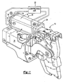
- FIG. 1 An inventive weld gun 10 including an inventive pneumatic cylinder 18 is shown in Figure 1 .
- the pneumatic cylinder 18 is a four port arrangement ports (P1-P4) that can be easily integrated into existing weld guns utilizing four ports. That is, the plumbing for prior art weld guns having four ports can be used with the inventive pneumatic cylinder 18 without modification to the welding system.
- the ports P1-P4 are fluidly connected to a compressed air source 22.
- the ports P1-P4 are connected to the compressed air source 22 though valves that control the timing of the air signals provided to the pneumatic cylinder 18 by selectively opening and closing the valves.
- the weld gun 10 includes opposing arms 12 that each include an electrode 14.
- the electrodes 14 include welding caps 16 that are typically manufactured from a malleable copper alloy.
- the welding caps 16 engage a workpiece (not shown) to apply a welding current to the workpiece to generate a weld nugget, as is well known in the art.
- the arms 12 are typically supported by the weld gun 10 and interconnected to one another at various pivot points.
- a rod 20 of the pneumatic cylinder 18 is typically connected to one of the arms 12 to actuate the electrodes 14 and welding cap 16 between electrode positions corresponding to home (fully returned), intermediate, and work (caps 16 and workpiece engaged) positions. Current is applied to the electrodes 14 when in the work position using a current source 24 that is electrically connected to the electrodes 14.
- Port P1 provides weld-forward air when pressurized.
- Port P2 provides weld-return air when pressurized.
- Port P3 provides retract-forward air when pressurized, and port P4 provides retract-return air when pressurized.
- the ports are pressurized in pairs to achieve a desired position with the other, non-pressurized ports vented to atmosphere.
- the weld-return and retract-return ports, P2 and P4 are pressurized to obtain the home position.
- the weld-return and retract-forward ports, P2 and P3, are pressurized to obtain the intermediate position.
- the weld-forward and retract-forward ports, P1 and P3, are pressurized to obtain the work position.
- the fully advanced work position is the travel limit of the work position.
- the rod 20 may be actuated between the above three positions or directly from the home position to the work position by actuating the desired valves. It should be understood that the work position is not necessarily a discrete position, but rather, may be any distance along which the rod 20 moves between the intermediate position and the fully advanced work position.
- the various positions and the condition at the ports is expressed in the following table: Weld-Forward Weld-Return Retract-Forward Retract-Return (P1) (P2) (P3) (P4) Home vented pressurized vented pressurized Intermediate vented pressurized pressurized vented Work pressurized vented pressurized vented pressurized vented vented
- the pneumatic cylinder 18 includes a cylinder body 26 that has a barrel 34 and an end cap 32 arranged at one end.
- a front block 28 is arranged at the other end of the barrel 34.
- the fasteners 36 secure the components of the cylinder body 26 together so the pneumatic cylinder 18 can be pressurized at ports P1-P4 without leakage from the cylinder body 26.
- the ports may be arranged on the cylinder other than described and shown. For example, the ports may be repositioned to provide desired packaging of the weld cylinder.
- the multiple component cylinder body 26 and its configuration described above are exemplary of a four/port pneumatic cylinder having a single piston arrangement. However, it should be understood that other configurations may be used and still fall within the scope of the present invention. For example, a dual cylinder incorporating the present invention is shown in Figure 9 .
- Figures 2 , 3A and 3B depict a home position of the pneumatic cylinder 18.
- Figures 4 and 5 show an intermediate position of the pneumatic cylinder 18, and
- Figures 6 and 7 depict a work position of the pneumatic cylinder 18.
- the work or weld position may lie anywhere between the intermediate position and the fully advanced position depending on the mechanical system and the workpiece. The position variation is used in the process to ensure the weld force is maintained as the electrodes deflect under mechanical load, the electrode wear, and as the workpiece becomes distorted during the welding process.
- a weld flange 64 is in close proximity to or engages a rearward flange 44.
- the present invention pneumatic cylinder 18 moves the rod 20 quickly from the home position ( Figure 2 ) to the intermediate position ( Figure 4 ) in which the welding caps 16 are in close proximity to the workpiece. However, the rod 20 moves more slowly from the intermediate position ( Figure 4 ) to the work position ( Figure 6 ) in which the welding caps 16 sufficiently forcefully engage the workpiece. The rod 20 moves forward and additional distance to increase the weld force so that current can be applied to produce a weld nugget. The slower movement from the intermediate position ( Figure 4 ) to the work position ( Figure 6 ) ensures that the impact force between the welding caps 16 and the workpiece is minimized. However, the preceding, more rapid movement of the rod 20 ensures that cycle time is not unduly compromised.
- the present invention reduces the impact force of the caps engaging the workpiece while not significantly increasing cycle times. Further, the invention decouples the retract stroke length of a cylinder from low impact performance. That is, the invention can meet desired low impact targets using the same components for cylinders having various retract stroke lengths.
- ports P1 and P3 are provided by the end cap 32. Ports P2 and P4 are provided by the front block 28, which also slideably supports the rod 20 with bushing 59.
- a retract piston assembly 40 is slideably supported by the barrel 34.
- the retract piston assembly 40 includes a barrel 46 having forward and rearward flanges 42 and 44 secured at opposite ends using retaining ribbons 48.
- the retract piston assembly 40 separates a cavity 50 provided by the barrel 34 into first and second chambers 52 and 54.
- the retract piston assembly 40 is shown in a retract-return position in Figure 2 and a retract-forward position in Figures 4 and 6 .
- the retract piston assembly 40 includes a weld flange 64, which is threadingly secured to an end of the rod 20 opposite an end 60 of the rod 20. The end 60 is secured to one of the arms 12.
- the weld flange 64 is arranged within the retract piston assembly 40 between the forward and rearward flanges 42 and 44 in a cavity 66 that is separated by the weld flange 64 into third and fourth chambers 68 and 70.
- the fourth chamber 70 acts as a cushion chamber to reduce the impact between the caps and the workpiece.
- the weld flange 64 is shown in a weld-return position in Figures 2 and 4 and moving toward a weld-forward position in Figure 6 .
- the work position depicted in Figure 6 includes a range of positions once the rod 20 begins to move. The rod 20 continues to advance a distance as the pressure builds to allow the weld-force pressure to build quickly.
- the inventive pneumatic cylinder 18 includes a cushion or differential pressure valve 78 supported by the rearward flange 44 of the retract piston assembly 40.
- a seal 82 is arranged between the cushion valve 78 and the return flange 44.
- a spring 84 is arranged between a plate 86, which is secured to the rearward flange 44 by screws 88 (only one shown), and the cushion valve 78.
- the spring 84 biases the cushion valve 78 to a closed position, which is shown in Figures 2 , 3A and 4 .
- the cushion valve 78 has a pre-orifice 73 that provides a predetermined, controlled leak of the pressurized cushion chamber 70 through passage 72.
- the retract piston assembly 40 includes notches 75. Wear bands 67 are arranged at the notches 75 to keep the retract piston assembly 40 centered within the barrel 34. An annular space 77 is provided between the barrels 34 and 46.
- the rearward flange 44 carries a seal 76 that provides a seal between the barrel 34 and the rearward flange 44.
- a passage 74 in the rearward flange 44 provides a fluid connection between one side of the cushion valve 78 and the retract-forward port P3.
- An isolator 80 is arranged concentric with and inside of the cushion valve 78.
- the isolator 80 is sealed against the cushion valve 78 with seals 79.
- a spring 81 acts against a retainer that is secured to the isolator 80 to bias the isolator 80 to the closed position shown in Figures 2 and 3A .
- the pressure in the cushion chamber 70 and spring 81 apply sufficient force to the isolator 80 to maintain the isolator 80 in the closed position with the retract-return air applied to the isolator from the second chamber 54.
- the front block 28 supports a trip valve 98 that is biased to a closed position against a plate 90 by a spring 92.
- the plate 90 is secured to the front block 28 by screws (not shown).
- a seal 100 is arranged between the rod 20 and the trip valve 98.
- the cushion chamber 70 has already been pressurized by weld-return air subsequent to welding the workpiece.
- the weld-return port P2 is actuated (along with the retract-return port P4) to obtain the home position of Figure 2 .
- the weld-return port P2 is pressurized, but pressurized air is prevented from acting on the retract piston assembly 40 with the trip valve 98 in the closed position.
- the retract-return port P4 provides pressurized air to the second chamber 54 to retain the retract piston assembly 40 in the retracted position.
- the intermediate position is shown in Figures 4 and 5 and is achieved by pressurizing the weld-return and retract-forward ports P2 and P3.
- the second chamber 54 is exhausted through vented retract-return port P4.
- Seals 102 on the rearward flange 44 engage the front block 28 and plate 90 to prevent the second chamber 54 from fully exhausting through the large passage 104. Instead, the remaining pressure in second chamber 54 is exhausted through cushion passage 106 thereby smoothing the engagement between retract piston assembly 40 and front block 28.
- the isolator 80 and trip valve 98 engage one another forcing both the isolator 80 and trip valve 98 to the open positions, best seen in Figure 5 .
- an opening 108 is created between the trip valve 98 and plate 90 to fluidly connect the weld-return port P2 and newly created chamber 110 through the opening 108.
- the opened isolator 80 provides an opening 112 between the isolator 80 and cushion valve 78 that is fluidly connected to an annular passage 114.
- a hole 115 in the cushion valve 78 (in addition to the pre-orifice 73) fluidly connects the annular passage 114 to the passage 72 so that the cushion chamber 70 is in fluid communication with the weld-return port P2.
- Pre-orifice 73 may be situated on rearward flange 44 instead of on cushion valve 78.
- pre-orifice 73 and hole 115 can each be comprised of one or more holes or passages.
- the pre-orifice 73 of a smaller net flow area than hole 115, allows only a small amount of cushion fluid to escape to the vented port P2, just enough to smooth the transition at the intermediate position when stroking from the home to work positions directly.
- the pressure in the cushion chamber 70 is "topped off” prior to actuating the cylinder to the work position.
- Prior embodiments allow cushion air to flow freely, to the point where insufficient pressure remains in the cushion chamber 70 for achieving low-impact operation, especially for cylinders with longer retract stroke lengths.
- the isolator 80 "isolates" the cushion chamber 70 from hole 115 so that during the retract stroke, cushion air can escape through the pre-orifice 73. This way, the transition at the intermediate position can be smoothed by the pre-orifice's effect of slightly reducing cushion pressure without compromising low-impact operation that would otherwise occur should cushion air be allowed to escape through hole 115 during the retract stroke.
- One side of the cushion valve 78 is exposed to pressure from the retract-forward port P3 through notches 75, annular space 77 and passage 74. However, the retract-forward pressure is not sufficient to overcome the weld-return pressure and the spring 84 to open the cushion valve 78.
- the cylinder is actuated from the intermediate position ( Figures 4 and 5 ) to the work position shown in Figures 6 and 7 by pressurizing the weld-forward port P1 and the retract-forward port P3.
- the weld-return port P2 is vented while the cushion chamber 70 and weld-return port P2 are still fluidly connected to one another.
- the pressurized fluid enters the third chamber 68 through passage 118 in tube 116 that is fluidly connected to the weld-forward port P1.
- the tube 116 is threaded into end cap 32 and sealed relative to forward flange 42 by seal 117.
- the weld flange 64 advances, but initially with the cushion valve 78 and isolator 80 in the positions shown in Figure 5 .
- the cylinder is actuated to either the intermediate or home positions by pressurizing the cushion chamber 70 with air from the weld-return port P2.
- the weld flange 64 is moved to the returned position. Once the cushion chamber 70 is filled, the pressure in the cushion chamber 70 will close the cushion valve 78.
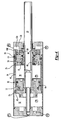
- the above inventive arrangement may also be used for a dual piston arrangement, shown in Figure 9 , which is similar to the single piston cylinder described above.
- the dual piston cylinder 18' includes a middle separator 30 dividing barrels 34a and 34b.
- the middle separator 30 acts as the front block described above relative to the single piston cylinder.
- a first rod portion 20a is supported by the middle separator 30, and a second rod portion 20b is supported by a front block 28'.
- a second weld flange 62 is secured between the rod portions 20a and 20b.
- a second weld-forward port P1 is provided on the middle separator 30 to provide pressurized air to the second weld flange 62.
- a vent is provided in the front block 28' to permit air to be exhausted from forward chamber 130.
- the cylinder may also be used as a five port cylinder by independently controlling the two ports labeled as P1 in Figure 9 .
Landscapes
- Engineering & Computer Science (AREA)
- Mechanical Engineering (AREA)
- Physics & Mathematics (AREA)
- Fluid Mechanics (AREA)
- General Engineering & Computer Science (AREA)
- Robotics (AREA)
- Actuator (AREA)
- Resistance Welding (AREA)
- Pistons, Piston Rings, And Cylinders (AREA)
Description
- The present invention relates to a weld gun used in spot welding, and more particularly, the invention relates to either a single or double piston welding cylinder for the weld gun generating a low impact force when the weld gun engages the workpiece to perform a spot weld.
- A typical weld gun used in spot welding includes opposing arms each having an electrode that applies current to a workpiece to generate a weld nugget, for example, between two sheets of metal. The electrodes include malleable welding caps typically manufactured from a copper alloy. Repeated impact force between the welding caps and the workpiece plastically deforms the welding caps thereby increasing the wear of the welding caps and reducing the service life, which increases operating cost.
- Impact force between the welding caps and workpiece also generates workpiece distortion, which can have detrimental effects on the welding process and quality of the weld.
- Several prior art weld cylinders have endeavored to reduce the impact force between the welding caps and workpiece to extend the life of welding caps and reduce workpiece distortion. One approach in the prior art has been to slow the advance of the electrodes toward one another by slowing the movement of the pneumatic cylinder. However, while this approach reduces the impact force it also increases the cycle time for a spot weld, which is undesirable. Another drawback is that typically the greater the retract stroke length, the narrower the low impact region becomes relative to the stroke. This is problematic in that the internal components of the weld cylinder must be customized depending upon the application. A more versatile weld cylinder design would provide common components for a wider variety of applications.
- Another approach in the prior art is to utilize external devices or peripheral components such as valves, regulators, restrictors, and/or electrical switches to control the pressure, timing, and rate that the air is supplied to the pneumatic cylinder thereby controlling the impact force. However, the addition of these externals devices may be difficult to integrate with existing weld guns and is also costly since additional components must be added to the welding system. It is desirable to use the current industry pneumatic actuating systems so that the inventive weld cylinder may be used with current systems. For example, in four weld port systems, the ports are typically pressurized in pairs to achieve the three different weld cylinder stroke positions.
- One of the ports on prior art systems is typically provided on a barrel that extends between the ends of the cylinder. The barrel port is a costly feature in that it requires a two-piece tubular wall with a separator arranged between the walls. The multiple components of the barrel must incorporate several seals. As an alternative to using the separator, the port may be welded to a singular tubular wall, which requires subsequent machining of the inner surface of the barrel. Further, the welding process is difficult to control.
- Therefore, what is needed is a pneumatic cylinder that reduces impact force between the welding caps and the workpiece but that does not require additional, costly design features or external devices and increases in cycle time.
-
US2003/0089684 discloses a modular welding gun, with an actuator rod of rectangular cross-section to prevent undesired rotation of welding arms. A number of weld arms are disclosed for use in various configurations of weld guns. Various drive systems and actuators are disclosed, including pulleys and pneumatic cylinders. -
US 2002/0117051 discloses a welding gun with a pneumatic cylinder whereby the cylinder is connected to a cushioning mechanism. Various methods of cushioning a weld gun cylinder are disclosed, comprising various valves external to the weld cylinder. - Aspects of the present invention are set forth in the
independent claims 1 and 16. - Preferred but non-essential features of the present invention are set forth in the dependent claims.
- The present provides a weld cylinder having a single or dual piston arrangement. The cylinder has a movable retract piston assembly with the piston arranged within the retract piston assembly. The piston supports a rod that is movable between home, intermediate, work, and fully advanced work positions. The rod moves rapidly from the home position to the intermediate position. However, the rod moves more slowly from the intermediate position to the work position to reduce the impact force. A cushion valve supported by the retract piston assembly and a cushion trip valve supported by a front block cooperate to increase the rate at which the rod moves from the work position to the advanced position so that weld force increases rapidly to minimize increases in cycle time.
- A weld-return port is provided on the front block so that weld-ports need not be provided on the barrel. A cushion chamber is pressurized using weld-return air. Notches are provided in the retract piston assembly to fluidly connect the retract-forward air to the cushion valve, which is carried by a rearward flange in the retract piston assembly.
- The cushion valve includes a pre-orifice to permit some cushion air to exhaust from the cushion chamber prior to reaching the intermediate position, which enables the rod to advance more smoothly and quickly. An isolator valve opens when it engages the trip valve during the advance of the retract piston assembly. The trip valve is also opened at this time. When both the cushion valve and cushion trip valve move from closed positions to open positions, the rate of fluid flow through the retract piston assembly increases, and so too does the rate at which the piston moves within the retract piston assembly.
- The cushion valve is a differential pressure valve that is exposed to the pressure within the cushion chamber and retract-forward air pressure. As the pressure in the cushion chamber falls as the chamber is exhausted and the retract-forward air pressure rises, the cushion valve will open. The opened cushion valve enables the cushion chamber to be exhausted even more rapidly so that the weld force can build quickly.
- A second cushion chamber is provided between the retract piston assembly and the front block to smooth engagement between the retract piston assembly and the front block. A sealed chamber is created between the rearward flange and the front block as the retract piston assembly approaches the front block. A passage fluidly connects the second cushion chamber and the retract-return port, which is vented to atmosphere at this cylinder position.
- Accordingly, the present invention provides a pneumatic cylinder that reduces initial impact force between the welding caps and the workpiece, but that does not require additional, costly external devices and increases in cycle time.
- These and other features of the present invention can be best understood from the following specification and drawings, the following of which is a brief description.
-
-
Figure 1 is a perspective view of an inventive weld gun. -
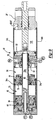
Figure 2 is a cross-sectional view of a single piston weld cylinder shown inFigure 1 in the home position. -
Figure 3A is an enlarged view of the rearward flange of the retract piston assembly shown inFigure 2 . -
Figure 3B is an enlarged view of the front block of the retract piston assembly shown inFigure 2 . -
Figure 4 is a cross-sectional view of single piston weld cylinder shown inFigure 1 in the intermediate position. -
Figure 5 is an enlarged view of the rearward flange engaging the front block, as shown inFigure 4 . -
Figure 6 is a cross-sectional view of single piston weld cylinder shown inFigure 1 in the work position. -
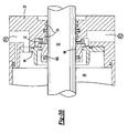
Figure 7 is an enlarged view of the rearward flange engaging the front block with the cushion valve open, as shown inFigure 6 . -
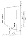
Figure 8 is a graphical depiction of the inventive pneumatic cylinder as compared to other cylinders. -
Figure 9 is a cross-sectional view of a dual piston weld cylinder in the home position. - An
inventive weld gun 10 including an inventivepneumatic cylinder 18 is shown inFigure 1 . Thepneumatic cylinder 18 is a four port arrangement ports (P1-P4) that can be easily integrated into existing weld guns utilizing four ports. That is, the plumbing for prior art weld guns having four ports can be used with the inventivepneumatic cylinder 18 without modification to the welding system. The ports P1-P4 are fluidly connected to acompressed air source 22. The ports P1-P4 are connected to thecompressed air source 22 though valves that control the timing of the air signals provided to thepneumatic cylinder 18 by selectively opening and closing the valves. - The
weld gun 10 includes opposingarms 12 that each include anelectrode 14. Theelectrodes 14 include welding caps 16 that are typically manufactured from a malleable copper alloy. The welding caps 16 engage a workpiece (not shown) to apply a welding current to the workpiece to generate a weld nugget, as is well known in the art. Thearms 12 are typically supported by theweld gun 10 and interconnected to one another at various pivot points. Arod 20 of thepneumatic cylinder 18 is typically connected to one of thearms 12 to actuate theelectrodes 14 andwelding cap 16 between electrode positions corresponding to home (fully returned), intermediate, and work (caps 16 and workpiece engaged) positions. Current is applied to theelectrodes 14 when in the work position using acurrent source 24 that is electrically connected to theelectrodes 14. - Port P1 provides weld-forward air when pressurized. Port P2 provides weld-return air when pressurized. Port P3 provides retract-forward air when pressurized, and port P4 provides retract-return air when pressurized. Typically, the ports are pressurized in pairs to achieve a desired position with the other, non-pressurized ports vented to atmosphere. In the example shown, the weld-return and retract-return ports, P2 and P4, are pressurized to obtain the home position. The weld-return and retract-forward ports, P2 and P3, are pressurized to obtain the intermediate position. The weld-forward and retract-forward ports, P1 and P3, are pressurized to obtain the work position. The fully advanced work position is the travel limit of the work position. The
rod 20 may be actuated between the above three positions or directly from the home position to the work position by actuating the desired valves. It should be understood that the work position is not necessarily a discrete position, but rather, may be any distance along which therod 20 moves between the intermediate position and the fully advanced work position. The various positions and the condition at the ports is expressed in the following table:Weld-Forward Weld-Return Retract-Forward Retract-Return (P1) (P2) (P3) (P4) Home vented pressurized vented pressurized Intermediate vented pressurized pressurized vented Work pressurized vented pressurized vented - The
pneumatic cylinder 18 includes acylinder body 26 that has abarrel 34 and anend cap 32 arranged at one end. Afront block 28 is arranged at the other end of thebarrel 34. Thefasteners 36 secure the components of thecylinder body 26 together so thepneumatic cylinder 18 can be pressurized at ports P1-P4 without leakage from thecylinder body 26. There is no port (typically the weld-return port) provided on theinventive barrel 34, as in some of the prior art and Applicant's other weld cylinders. Instead, the weld-return port is provided on thefront block 28. It should be understood that the ports may be arranged on the cylinder other than described and shown. For example, the ports may be repositioned to provide desired packaging of the weld cylinder. - The multiple
component cylinder body 26 and its configuration described above are exemplary of a four/port pneumatic cylinder having a single piston arrangement. However, it should be understood that other configurations may be used and still fall within the scope of the present invention. For example, a dual cylinder incorporating the present invention is shown inFigure 9 . - In the example embodiment of the inventive
pneumatic cylinder 18, three cylinder positions are generated.Figures 2 ,3A and3B depict a home position of thepneumatic cylinder 18.Figures 4 and5 show an intermediate position of thepneumatic cylinder 18, andFigures 6 and7 depict a work position of thepneumatic cylinder 18. The work or weld position may lie anywhere between the intermediate position and the fully advanced position depending on the mechanical system and the workpiece. The position variation is used in the process to ensure the weld force is maintained as the electrodes deflect under mechanical load, the electrode wear, and as the workpiece becomes distorted during the welding process. In the fully advanced position, aweld flange 64 is in close proximity to or engages arearward flange 44. - The present invention
pneumatic cylinder 18 moves therod 20 quickly from the home position (Figure 2 ) to the intermediate position (Figure 4 ) in which the welding caps 16 are in close proximity to the workpiece. However, therod 20 moves more slowly from the intermediate position (Figure 4 ) to the work position (Figure 6 ) in which the welding caps 16 sufficiently forcefully engage the workpiece. Therod 20 moves forward and additional distance to increase the weld force so that current can be applied to produce a weld nugget. The slower movement from the intermediate position (Figure 4 ) to the work position (Figure 6 ) ensures that the impact force between the welding caps 16 and the workpiece is minimized. However, the preceding, more rapid movement of therod 20 ensures that cycle time is not unduly compromised. The present invention reduces the impact force of the caps engaging the workpiece while not significantly increasing cycle times. Further, the invention decouples the retract stroke length of a cylinder from low impact performance. That is, the invention can meet desired low impact targets using the same components for cylinders having various retract stroke lengths. - Referring to
Figure 2 , ports P1 and P3 are provided by theend cap 32. Ports P2 and P4 are provided by thefront block 28, which also slideably supports therod 20 withbushing 59. A retractpiston assembly 40 is slideably supported by thebarrel 34. The retractpiston assembly 40 includes abarrel 46 having forward andrearward flanges ribbons 48. The retractpiston assembly 40 separates acavity 50 provided by thebarrel 34 into first andsecond chambers piston assembly 40 is shown in a retract-return position inFigure 2 and a retract-forward position inFigures 4 and6 . - The retract
piston assembly 40 includes aweld flange 64, which is threadingly secured to an end of therod 20 opposite anend 60 of therod 20. Theend 60 is secured to one of thearms 12. Theweld flange 64 is arranged within the retractpiston assembly 40 between the forward andrearward flanges cavity 66 that is separated by theweld flange 64 into third andfourth chambers fourth chamber 70 acts as a cushion chamber to reduce the impact between the caps and the workpiece. Theweld flange 64 is shown in a weld-return position inFigures 2 and4 and moving toward a weld-forward position inFigure 6 . The work position depicted inFigure 6 includes a range of positions once therod 20 begins to move. Therod 20 continues to advance a distance as the pressure builds to allow the weld-force pressure to build quickly. - Referring to
Figure 3A , the inventivepneumatic cylinder 18 includes a cushion ordifferential pressure valve 78 supported by therearward flange 44 of the retractpiston assembly 40. A seal 82 is arranged between thecushion valve 78 and thereturn flange 44. Aspring 84 is arranged between aplate 86, which is secured to therearward flange 44 by screws 88 (only one shown), and thecushion valve 78. Thespring 84 biases thecushion valve 78 to a closed position, which is shown inFigures 2 ,3A and4 . Thecushion valve 78 has a pre-orifice 73 that provides a predetermined, controlled leak of thepressurized cushion chamber 70 throughpassage 72. - The retract
piston assembly 40 includesnotches 75. Wearbands 67 are arranged at thenotches 75 to keep the retractpiston assembly 40 centered within thebarrel 34. Anannular space 77 is provided between thebarrels rearward flange 44 carries aseal 76 that provides a seal between thebarrel 34 and therearward flange 44. Apassage 74 in therearward flange 44 provides a fluid connection between one side of thecushion valve 78 and the retract-forward port P3. - An
isolator 80 is arranged concentric with and inside of thecushion valve 78. Theisolator 80 is sealed against thecushion valve 78 withseals 79. Aspring 81 acts against a retainer that is secured to theisolator 80 to bias theisolator 80 to the closed position shown inFigures 2 and3A . The pressure in thecushion chamber 70 andspring 81 apply sufficient force to theisolator 80 to maintain theisolator 80 in the closed position with the retract-return air applied to the isolator from thesecond chamber 54. - Referring to
Figure 3B , thefront block 28 supports atrip valve 98 that is biased to a closed position against aplate 90 by aspring 92. Theplate 90 is secured to thefront block 28 by screws (not shown). Aseal 100 is arranged between therod 20 and thetrip valve 98. - With continuing reference to
Figures 2 ,3A and3B , which depict the home position, thecushion chamber 70 has already been pressurized by weld-return air subsequent to welding the workpiece. Specifically, from the work position shown inFigure 6 , the weld-return port P2 is actuated (along with the retract-return port P4) to obtain the home position ofFigure 2 . However, in the home position ofFigure 2 , the weld-return port P2 is pressurized, but pressurized air is prevented from acting on the retractpiston assembly 40 with thetrip valve 98 in the closed position. The retract-return port P4 provides pressurized air to thesecond chamber 54 to retain the retractpiston assembly 40 in the retracted position. - The intermediate position is shown in
Figures 4 and5 and is achieved by pressurizing the weld-return and retract-forward ports P2 and P3. As thefirst chamber 52 is pressurized, thesecond chamber 54 is exhausted through vented retract-return port P4.Seals 102 on therearward flange 44 engage thefront block 28 andplate 90 to prevent thesecond chamber 54 from fully exhausting through thelarge passage 104. Instead, the remaining pressure insecond chamber 54 is exhausted throughcushion passage 106 thereby smoothing the engagement between retractpiston assembly 40 andfront block 28. - The
isolator 80 andtrip valve 98 engage one another forcing both theisolator 80 andtrip valve 98 to the open positions, best seen inFigure 5 . As a result, anopening 108 is created between thetrip valve 98 andplate 90 to fluidly connect the weld-return port P2 and newly createdchamber 110 through theopening 108. - The opened
isolator 80 provides anopening 112 between the isolator 80 andcushion valve 78 that is fluidly connected to anannular passage 114. Ahole 115 in the cushion valve 78 (in addition to the pre-orifice 73) fluidly connects theannular passage 114 to thepassage 72 so that thecushion chamber 70 is in fluid communication with the weld-return port P2.Pre-orifice 73 may be situated onrearward flange 44 instead of oncushion valve 78. Furthermore,pre-orifice 73 andhole 115 can each be comprised of one or more holes or passages. The pre-orifice 73, of a smaller net flow area thanhole 115, allows only a small amount of cushion fluid to escape to the vented port P2, just enough to smooth the transition at the intermediate position when stroking from the home to work positions directly. The pressure in thecushion chamber 70 is "topped off" prior to actuating the cylinder to the work position. - Prior embodiments allow cushion air to flow freely, to the point where insufficient pressure remains in the
cushion chamber 70 for achieving low-impact operation, especially for cylinders with longer retract stroke lengths. Theisolator 80 "isolates" thecushion chamber 70 fromhole 115 so that during the retract stroke, cushion air can escape through thepre-orifice 73. This way, the transition at the intermediate position can be smoothed by the pre-orifice's effect of slightly reducing cushion pressure without compromising low-impact operation that would otherwise occur should cushion air be allowed to escape throughhole 115 during the retract stroke. - One side of the
cushion valve 78 is exposed to pressure from the retract-forward port P3 throughnotches 75,annular space 77 andpassage 74. However, the retract-forward pressure is not sufficient to overcome the weld-return pressure and thespring 84 to open thecushion valve 78. - The cylinder is actuated from the intermediate position (
Figures 4 and5 ) to the work position shown inFigures 6 and7 by pressurizing the weld-forward port P1 and the retract-forward port P3. The weld-return port P2 is vented while thecushion chamber 70 and weld-return port P2 are still fluidly connected to one another. - Referring to
Figures 6 and7 , the pressurized fluid enters thethird chamber 68 throughpassage 118 intube 116 that is fluidly connected to the weld-forward port P1. Thetube 116 is threaded intoend cap 32 and sealed relative to forwardflange 42 byseal 117. As the pressure rises in thethird chamber 68, theweld flange 64 advances, but initially with thecushion valve 78 andisolator 80 in the positions shown inFigure 5 . - With reference to
Figure 5 , as theweld flange 64 advances, the air fromcushion chamber 70 is exhausted slowly through the pre-orifice 73 andhole 115 out weld-return port P2 to cushion the contact between the weld caps and the workpiece. The pressure incushion chamber 70 finally drops to a level at which pressure from the retract-forward port P3 atpassage 74 overcomes the pressure incushion chamber 70 andspring 84 to open thecushion valve 78, as shown inFigure 7 . Pressure inpassage 74 acts on a side of thecushion valve 78 exposed to acavity 122. Thecushion valve 78 engages theisolator 80 in the open position. In the open position, the air in thecushion chamber 70 is permitted to exhaust rapidly throughannular opening 124 out the weld-return port P2 so that welding force can rise rapidly. The effects of the controlled exhausting ofcushion chamber 70 of the inventive cylinder are shown inFigure 8 . By comparison, the harsh impact of other cylinders is eliminated. The "switch" inFigure 8 indicates the triggering of the valves to pressurize ports P1 and P3. - The cylinder is actuated to either the intermediate or home positions by pressurizing the
cushion chamber 70 with air from the weld-return port P2. Theweld flange 64 is moved to the returned position. Once thecushion chamber 70 is filled, the pressure in thecushion chamber 70 will close thecushion valve 78. - The above inventive arrangement may also be used for a dual piston arrangement, shown in
Figure 9 , which is similar to the single piston cylinder described above. The dual piston cylinder 18' includes amiddle separator 30 dividingbarrels middle separator 30 acts as the front block described above relative to the single piston cylinder. Afirst rod portion 20a is supported by themiddle separator 30, and a second rod portion 20b is supported by a front block 28'. Asecond weld flange 62 is secured between therod portions 20a and 20b. A second weld-forward port P1 is provided on themiddle separator 30 to provide pressurized air to thesecond weld flange 62. A vent is provided in the front block 28' to permit air to be exhausted fromforward chamber 130. The cylinder may also be used as a five port cylinder by independently controlling the two ports labeled as P1 inFigure 9 . - Although a preferred embodiment of this invention has been disclosed, a worker of ordinary skill in this art would recognize that certain modifications would come within the scope of this invention. For that reason, the following claims should be studied to determine the true scope and content of this invention.
Claims (21)
- A weld cylinder comprising:a cylinder (18) supporting a rod (20) providing home, intermediate and work positions;a retract piston assembly (40) arranged in the cylinder (18) which separates the cylinder (18) into first and second chambers (52, 54) and is movable between retract-return and retract-forward positions;a weld flange (64) arranged in the retract piston assembly (40) and movable between weld-return and weld-forward positions, the weld flange (64) supporting the rod (20), and separating a cavity of the retract piston assembly (40) into third and fourth chambers (68,70);retract-return (P4), weld-return (P2), retract-forward (P3) and weld-forward (P1) ports pressurized to provide the corresponding retract-return, weld-return, retract-forward and weld-forward positions, wherein the home position corresponds to the retract-return and weld-return positions with the non-corresponding ports (P3, P1) vented and the second and foutrh chambers (54, 70) pressurized the intermediate position corresponds to the retract-forward and weld-return positions with the non-corresponding ports (P4, P1) vented and the first and fourth chambers (52, 70) pressurized the work position corresponds to the retract-forward and weld-forward positions with the non-corresponding ports (P4, P2) vented and the first and third chambers (52,68) pressurized; characterized by the fourth chamber (70) pressurized using weld-return (P2) air acting as a cushion chamber; whereina differential pressure cushion valve (78) is fluidly connected to the weld-return (P2) and retract- forward (P3) ports in at least one of the intermediate and work positions in which the differential pressure cushion valve (78) is actuated between closed and open positions, the differential pressure cushion valve (78) being exposed to the pressure within the cushion chamber (70) and retract-forward (P3) air pressure; wherein the differential pressure cushion valve (78) will open as the pressure in the cushion chamber (70) falls as the chamber (70) is exhausted and the retract- forward (P3) air pressure rises.
- The weld cylinder according to claim 1, wherein the cylinder (18) includes a barrel (34) supported between a front block (28) and an end cap (32), and the retract piston assembly (40) includes a second barrel (46) arranged between forward (42) and rearward (44) flanges, the weld flange (64) arranged between the forward (42) and rearward (44) flanges within the second barrel (46) and annular space (77) between the barrels (34, 46).
- The weld cylinder according to claim 2, wherein the forward flange (42) including a slot (75) and the rearward flange (44) including a passage (74), with the annular space (77), slot (75) and passage (74) in fluid communication with the retract-forward port (P3).
- The weld cylinder according to claim 3, wherein a seal (76) is arranged between the rearward flange (44) and the barrel (34).
- The weld cylinder according to claim 3, wherein the passage (74) provides pressurized fluid to the differential pressure valve (78) in the work position to move the differential pressure valve (78) to the open position.
- The weld cylinder according to claim 5, wherein a spring (84) coacts with the differential pressure valve (78) to oppose movement from the closed position to the open position.
- The weld cylinder according to claim 5, wherein the cushion chamber (70) between the weld (64) and rearward (44) flanges exhausts at a first rate prior to the intermediate position and at a second rate in the work position, the second rate greater than the first rate.
- The weld cylinder according to claim 1, wherein the differential pressure cushion valve (78) is supported by the retract piston assembly (40), and the differential pressure cushion valve (78) cooperates with a cushion trip valve (98) supported by a front block (28) to increase the rate at which the rod (20) moves from the work position to the advanced position so that weld force increases rapidly to minimize increases in cycle time.
- The weld cylinder according to claim 8, wherein an isolator valve (80) opens when it engages the cushion trip valve (98) during the advance of the retract piston assembly (40).
- The weld cylinder according to claim 9, wherein the cushion trip valve (98) in the open position fluidly connects the weld-return port (P2) to the differential pressure cushion valve (78).
- The weld cylinder according to claim 10, wherein the isolator (80) is arranged concentric with the differential pressure cushion valve (78).
- The weld cylinder according to either of claims 10 or 11, wherein the isolator (80) is biased to the closed position by a spring (81), the isolator (80) maintaining the differential pressure cushion valve (78) in the closed position when the isolator (80) is in its closed position.
- The weld cylinder according to claim 12, wherein the differential pressure cushion valve (78) includes a hole (115), the hole (115) fluidly connected to the cushion chamber (70) with the isolator (80) in the open position and the differential pressure cushion valve (78) in the closed position, wherein the cushion chamber (70) is exhausted through the hole (115) with the differential pressure cushion valve (78) in the closed position.
- The weld cylinder according to claim 13, wherein the differential pressure cushion valve (78) moves from the closed position to the open position and against the isolator (80) when in its open position to provide an annular opening (124) between the differential pressure cushion valve (78) and a rearward flange (44) of the retract piston assembly (40), the cushion chamber (70) exhausting through the annular opening (124) with the differential pressure cushion valve (78) in the open position.
- The weld cylinder according to claim 1, wherein the cylinder (18) includes a trip valve (98), an isolator (80) engaging the trip valve (98) in the retract-forward position to open the trip valve (98), the open trip valve (98) fluidly connecting a pressure port (P2) to the differential pressure cushion valve (78).
- A method of welding by moving the weld cylinder according to any of claims 1-15 from a retracted weld position to an extended weld position, the method comprising the steps of:a) filling a cushion chamber (70) in a weld cylinder (18) that opposes movement from the retracted weld position to the extended weld position;b) exhausting fluid from the cushion chamber (70) through a pre-orifice (73) in the weld cylinder (18) while a differential pressure valve (78) in the weld cylinder (18) is in a closed position, the differential pressure valve (78) fluidly connected to weld-return (P2) and retract- forward (P3) ports in at least one of an intermediate and work position;c) opening an isolator valve (80) in the weld cylinder (18) while the differential pressure valve (78) is in the closed position to create a passage (72) and exhausting fluid from the cushion chamber (70) through the passage (72); andd) opening the differential pressure valve (78) to rapidly exhaust the fluid from the cushion chamber (70).
- The method according to claim 16, wherein the method includes movement between home, intermediate and work positions.
- The method according to claim 16, wherein step a) includes fluidly connecting the weld-return port (P2) with the cushion chamber (70) by opening a trip valve (98).
- The method according to claim 18, wherein step a) includes engaging the trip valve (98) with the isolator valve (80) to open the trip valve (98).
- The method according to claim 16, wherein step d) is performed by increasing a retract-forward pressure while exhausting the cushion chamber (70).
- The method according to claim 16, wherein the differential pressure (78) and isolator valves (80) are spring biased to closed positions prior to performing step b).
Applications Claiming Priority (2)
| Application Number | Priority Date | Filing Date | Title |
|---|---|---|---|
| US63508604P | 2004-12-10 | 2004-12-10 | |
| PCT/CA2005/001239 WO2006060891A1 (en) | 2004-12-10 | 2005-08-11 | Low impact spot welding cylinder using single or double piston |
Publications (3)
| Publication Number | Publication Date |
|---|---|
| EP1819474A1 EP1819474A1 (en) | 2007-08-22 |
| EP1819474A4 EP1819474A4 (en) | 2008-11-19 |
| EP1819474B1 true EP1819474B1 (en) | 2014-02-26 |
Family
ID=36577623
Family Applications (1)
| Application Number | Title | Priority Date | Filing Date |
|---|---|---|---|
| EP05772221.7A Expired - Lifetime EP1819474B1 (en) | 2004-12-10 | 2005-08-11 | Low impact spot welding cylinder using single or double piston |
Country Status (7)
| Country | Link |
|---|---|
| US (3) | US8629369B2 (en) |
| EP (1) | EP1819474B1 (en) |
| JP (2) | JP4891915B2 (en) |
| CN (1) | CN100531995C (en) |
| CA (1) | CA2587596C (en) |
| ES (1) | ES2464784T3 (en) |
| WO (1) | WO2006060891A1 (en) |
Families Citing this family (17)
| Publication number | Priority date | Publication date | Assignee | Title |
|---|---|---|---|---|
| US8629369B2 (en) * | 2004-12-10 | 2014-01-14 | Doben Limited | Low impact spot welding cylinder using single or double piston |
| US8453557B2 (en) * | 2009-08-28 | 2013-06-04 | GM Global Technology Operations LLC | Piston actuator assembly |
| CN101972910B (en) * | 2010-10-30 | 2013-04-17 | 长城汽车股份有限公司 | Mechanical stepping mechanism for positioning welding tongs |
| CN102072218A (en) * | 2010-11-15 | 2011-05-25 | 昆山市汇新电气机械有限公司 | Double-piston portal cylinder |
| CN102297179A (en) * | 2011-07-24 | 2011-12-28 | 徐工集团工程机械股份有限公司江苏徐州工程机械研究院 | Multi-stage lifting oil cylinder buffer mechanism |
| CN102536958B (en) * | 2012-02-24 | 2016-02-03 | 常州轩达液压机电设备有限公司 | Vertical roller mill buffering device |
| CN104139262A (en) * | 2014-07-17 | 2014-11-12 | 苏州市华宁机械制造有限公司 | Welding gun regulating device |
| CN104389849B (en) * | 2014-10-13 | 2016-08-17 | 中国运载火箭技术研究院 | A kind of buffering acting device being applicable to gas actuation |
| CN105499857B (en) * | 2016-01-21 | 2017-10-20 | 永嘉县恒正阀门有限公司 | Semi-automatic flap built-up welder and bead-welding technology |
| US10132337B2 (en) * | 2016-04-28 | 2018-11-20 | Qtrco, Inc. | Actuator assembly for conducting partial stroke testing |
| CN107725525B (en) * | 2016-08-12 | 2020-01-07 | Smc(中国)有限公司 | Welding gun cylinder |
| DE102017112448A1 (en) * | 2017-06-06 | 2018-12-06 | Arnold & Shinjo Gmbh & Co. Kg | Apparatus and method for producing a composite component and motor vehicle |
| KR102694175B1 (en) * | 2019-12-05 | 2024-08-12 | 다드코 인코퍼레이티드 | pneumatic cylinder |
| US12146589B2 (en) * | 2021-03-16 | 2024-11-19 | Qtrco, Inc. | Actuator assembly for conducting partial stroke testing |
| CN115488459B (en) * | 2022-09-15 | 2024-01-16 | 西南应用磁学研究所(中国电子科技集团公司第九研究所) | Method for improving center conductor cold joint defect of lumped parameter circulator/isolator |
| CN116538168A (en) * | 2023-05-30 | 2023-08-04 | 苏州苏试试验集团股份有限公司 | Impact cylinder and impact test device |
| CN121267549B (en) * | 2025-12-09 | 2026-03-20 | 无锡恒立液压气动有限公司 | A hydraulic cylinder circumferential welder with liquid-gas separation |
Family Cites Families (21)
| Publication number | Priority date | Publication date | Assignee | Title |
|---|---|---|---|---|
| US4135076A (en) * | 1977-04-11 | 1979-01-16 | Beneteau Donald J | Apparatus for resistance welding |
| SE414527B (en) * | 1978-11-07 | 1980-08-04 | Volvo Ab | CYLINDER WITH TWICE STEP, SPECIFICALLY A SWEAT CYLINDER |
| JPS6051305U (en) * | 1983-09-17 | 1985-04-11 | エスエムシ−株式会社 | Pneumatic cylinder with cushion mechanism |
| GB2242847B (en) * | 1990-04-12 | 1993-10-13 | Savair Ltd | Welding gun assembly and fluid actuated cylinder |
| US5789719A (en) * | 1991-05-02 | 1998-08-04 | Milco Manufacturing Co. | Method and apparatus for electrical resistance spot welding |
| JP2557633Y2 (en) * | 1991-06-03 | 1997-12-10 | 小原株式会社 | 4 port 2 stage stroke cylinder for welding machine |
| US5275540A (en) * | 1992-03-17 | 1994-01-04 | Brown Harold D | Linear fluid motor system |
| US5191825A (en) * | 1992-06-12 | 1993-03-09 | Doben Limited | Low-impact air cylinder |
| GB9314145D0 (en) * | 1993-07-08 | 1993-08-18 | Savair Ltd | Pneumatic cylinder and control valve therefor |
| JP2648291B2 (en) * | 1995-05-16 | 1997-08-27 | 有限会社ヒロタカエンジニアリング | Electrode drive of spot welding machine |
| US5796067A (en) * | 1995-10-30 | 1998-08-18 | The Lincoln Electric Company | Plasma arc torches and methods of operating and testing the same |
| JPH10211582A (en) * | 1997-01-24 | 1998-08-11 | Inoue Seisakusho:Kk | Resistance welding equipment |
| US6054669A (en) * | 1998-05-20 | 2000-04-25 | The Esab Group, Inc. | Plasma marking torch and method of operating same |
| US6870121B2 (en) * | 1999-08-17 | 2005-03-22 | Milco Manufacturing Co. | Modular welding guns |
| US6528948B1 (en) * | 2000-10-11 | 2003-03-04 | Brookhaven Science Associates Llc | Plasma valve |
| US6408740B1 (en) * | 2000-12-04 | 2002-06-25 | Welker Bearing Company | Three position cylinder |
| JP3696103B2 (en) * | 2001-02-23 | 2005-09-14 | Smc株式会社 | High speed pressurizing method and mechanism in cylinder with cushion mechanism |
| ITTO20020786A1 (en) * | 2002-09-10 | 2004-03-11 | Gerbi & Fase S P A | DOUBLE STROKE ACTUATOR CYLINDER, PARTICULARLY FOR |
| US7223933B2 (en) * | 2004-01-21 | 2007-05-29 | Doben Limited | Low impact spot welding cylinder with single piston |
| US8629369B2 (en) * | 2004-12-10 | 2014-01-14 | Doben Limited | Low impact spot welding cylinder using single or double piston |
| US7214902B2 (en) * | 2004-12-13 | 2007-05-08 | Doben Limited | Low impact spot welding cylinder with dual pistons |
-
2005
- 2005-08-11 US US12/676,784 patent/US8629369B2/en active Active
- 2005-08-11 CA CA2587596A patent/CA2587596C/en not_active Expired - Lifetime
- 2005-08-11 CN CNB2005800396455A patent/CN100531995C/en not_active Expired - Fee Related
- 2005-08-11 WO PCT/CA2005/001239 patent/WO2006060891A1/en not_active Ceased
- 2005-08-11 EP EP05772221.7A patent/EP1819474B1/en not_active Expired - Lifetime
- 2005-08-11 ES ES05772221.7T patent/ES2464784T3/en not_active Expired - Lifetime
- 2005-08-11 JP JP2007544703A patent/JP4891915B2/en not_active Expired - Fee Related
- 2005-12-09 US US11/298,812 patent/US7714247B2/en active Active
- 2005-12-09 US US11/297,915 patent/US7718916B2/en active Active
-
2011
- 2011-04-04 JP JP2011082771A patent/JP5409687B2/en not_active Expired - Fee Related
Also Published As
| Publication number | Publication date |
|---|---|
| JP4891915B2 (en) | 2012-03-07 |
| US20100213246A1 (en) | 2010-08-26 |
| CN100531995C (en) | 2009-08-26 |
| WO2006060891A1 (en) | 2006-06-15 |
| JP5409687B2 (en) | 2014-02-05 |
| US7714247B2 (en) | 2010-05-11 |
| CN101060953A (en) | 2007-10-24 |
| CA2587596A1 (en) | 2006-06-15 |
| ES2464784T3 (en) | 2014-06-04 |
| EP1819474A4 (en) | 2008-11-19 |
| US20060124606A1 (en) | 2006-06-15 |
| US20060124607A1 (en) | 2006-06-15 |
| EP1819474A1 (en) | 2007-08-22 |
| JP2008522825A (en) | 2008-07-03 |
| US8629369B2 (en) | 2014-01-14 |
| US7718916B2 (en) | 2010-05-18 |
| JP2011167767A (en) | 2011-09-01 |
| CA2587596C (en) | 2015-12-29 |
Similar Documents
| Publication | Publication Date | Title |
|---|---|---|
| US8629369B2 (en) | Low impact spot welding cylinder using single or double piston | |
| US5060362A (en) | Slug riveting method and apparatus with C-frame deflection compensation | |
| US6722257B2 (en) | Workpiece high-speed pressurizing method and mechanism by using cylinder with cushioning mechanism | |
| EP0633402B1 (en) | Pneumatic cylinder and control valve therefor | |
| US7223933B2 (en) | Low impact spot welding cylinder with single piston | |
| KR20000053334A (en) | Peneumatic or hydraulic control motor with a shutoff device | |
| US7214902B2 (en) | Low impact spot welding cylinder with dual pistons | |
| US7337885B2 (en) | Telescoping cylinder | |
| US4819541A (en) | Control of a double-action pneumatic drive | |
| US6198065B1 (en) | Resistance welding process and device | |
| EP0428406A1 (en) | Reciprocating actuator | |
| US7952046B2 (en) | Resistance welding gun with independent actuators | |
| JP4431928B2 (en) | Multi-stroke cylinder | |
| US20030070541A1 (en) | Variable-stroke pneumatic cylinder | |
| JP3247166U (en) | Chuck device and chuck system | |
| JP2001198680A (en) | Electrode pressurization control method and apparatus for resistance welding machine | |
| US20220226924A1 (en) | Resistance spot welding apparatus | |
| JPH10213104A (en) | Telescopic cylinder | |
| KR20030089551A (en) | Damping control device in hydraulic cylinder | |
| JP2005282739A (en) | Cylinder device | |
| JP3781219B2 (en) | Cylinder equipment | |
| JPH08224670A (en) | C type welding gun for robot | |
| KR20030039398A (en) | Damper in hydraulic cylinder | |
| JPS59199185A (en) | Spot welding gun |
Legal Events
| Date | Code | Title | Description |
|---|---|---|---|
| PUAI | Public reference made under article 153(3) epc to a published international application that has entered the european phase |
Free format text: ORIGINAL CODE: 0009012 |
|
| 17P | Request for examination filed |
Effective date: 20070420 |
|
| AK | Designated contracting states |
Kind code of ref document: A1 Designated state(s): DE ES FR |
|
| RIN1 | Information on inventor provided before grant (corrected) |
Inventor name: TENZER, PETER |
|
| DAX | Request for extension of the european patent (deleted) | ||
| RBV | Designated contracting states (corrected) |
Designated state(s): DE ES FR |
|
| A4 | Supplementary search report drawn up and despatched |
Effective date: 20081021 |
|
| 17Q | First examination report despatched |
Effective date: 20090128 |
|
| GRAP | Despatch of communication of intention to grant a patent |
Free format text: ORIGINAL CODE: EPIDOSNIGR1 |
|
| INTG | Intention to grant announced |
Effective date: 20131021 |
|
| GRAS | Grant fee paid |
Free format text: ORIGINAL CODE: EPIDOSNIGR3 |
|
| GRAA | (expected) grant |
Free format text: ORIGINAL CODE: 0009210 |
|
| AK | Designated contracting states |
Kind code of ref document: B1 Designated state(s): DE ES FR |
|
| REG | Reference to a national code |
Ref country code: DE Ref legal event code: R096 Ref document number: 602005042771 Country of ref document: DE Effective date: 20140410 |
|
| REG | Reference to a national code |
Ref country code: ES Ref legal event code: FG2A Ref document number: 2464784 Country of ref document: ES Kind code of ref document: T3 Effective date: 20140604 |
|
| REG | Reference to a national code |
Ref country code: DE Ref legal event code: R097 Ref document number: 602005042771 Country of ref document: DE |
|
| PLBE | No opposition filed within time limit |
Free format text: ORIGINAL CODE: 0009261 |
|
| STAA | Information on the status of an ep patent application or granted ep patent |
Free format text: STATUS: NO OPPOSITION FILED WITHIN TIME LIMIT |
|
| 26N | No opposition filed |
Effective date: 20141127 |
|
| REG | Reference to a national code |
Ref country code: DE Ref legal event code: R097 Ref document number: 602005042771 Country of ref document: DE Effective date: 20141127 |
|
| REG | Reference to a national code |
Ref country code: FR Ref legal event code: ST Effective date: 20150430 |
|
| PG25 | Lapsed in a contracting state [announced via postgrant information from national office to epo] |
Ref country code: FR Free format text: LAPSE BECAUSE OF NON-PAYMENT OF DUE FEES Effective date: 20140901 |
|
| REG | Reference to a national code |
Ref country code: ES Ref legal event code: FD2A Effective date: 20150928 |
|
| PG25 | Lapsed in a contracting state [announced via postgrant information from national office to epo] |
Ref country code: ES Free format text: LAPSE BECAUSE OF NON-PAYMENT OF DUE FEES Effective date: 20140812 |
|
| PGFP | Annual fee paid to national office [announced via postgrant information from national office to epo] |
Ref country code: DE Payment date: 20170808 Year of fee payment: 13 |
|
| REG | Reference to a national code |
Ref country code: DE Ref legal event code: R119 Ref document number: 602005042771 Country of ref document: DE |
|
| PG25 | Lapsed in a contracting state [announced via postgrant information from national office to epo] |
Ref country code: DE Free format text: LAPSE BECAUSE OF NON-PAYMENT OF DUE FEES Effective date: 20190301 |