EP1819157A2 - Projection display apparatus - Google Patents
Projection display apparatus Download PDFInfo
- Publication number
- EP1819157A2 EP1819157A2 EP07101924A EP07101924A EP1819157A2 EP 1819157 A2 EP1819157 A2 EP 1819157A2 EP 07101924 A EP07101924 A EP 07101924A EP 07101924 A EP07101924 A EP 07101924A EP 1819157 A2 EP1819157 A2 EP 1819157A2
- Authority
- EP
- European Patent Office
- Prior art keywords
- display apparatus
- unit
- horizontal reference
- acceleration sensor
- projection display
- Prior art date
- Legal status (The legal status is an assumption and is not a legal conclusion. Google has not performed a legal analysis and makes no representation as to the accuracy of the status listed.)
- Withdrawn
Links
- 238000001514 detection method Methods 0.000 claims abstract description 17
- 230000001133 acceleration Effects 0.000 description 59
- 238000000034 method Methods 0.000 description 22
- 230000003287 optical effect Effects 0.000 description 16
- 230000035945 sensitivity Effects 0.000 description 11
- 230000006870 function Effects 0.000 description 8
- 238000009434 installation Methods 0.000 description 8
- 230000015654 memory Effects 0.000 description 6
- NCGICGYLBXGBGN-UHFFFAOYSA-N 3-morpholin-4-yl-1-oxa-3-azonia-2-azanidacyclopent-3-en-5-imine;hydrochloride Chemical compound Cl.[N-]1OC(=N)C=[N+]1N1CCOCC1 NCGICGYLBXGBGN-UHFFFAOYSA-N 0.000 description 4
- 238000010586 diagram Methods 0.000 description 4
- 238000006243 chemical reaction Methods 0.000 description 3
- 230000005484 gravity Effects 0.000 description 3
- 239000004973 liquid crystal related substance Substances 0.000 description 1
- 238000012986 modification Methods 0.000 description 1
- 230000004048 modification Effects 0.000 description 1
- 239000004065 semiconductor Substances 0.000 description 1
- 239000000758 substrate Substances 0.000 description 1
Images




Classifications
-
- H—ELECTRICITY
- H04—ELECTRIC COMMUNICATION TECHNIQUE
- H04N—PICTORIAL COMMUNICATION, e.g. TELEVISION
- H04N9/00—Details of colour television systems
- H04N9/12—Picture reproducers
- H04N9/31—Projection devices for colour picture display, e.g. using electronic spatial light modulators [ESLM]
- H04N9/3197—Projection devices for colour picture display, e.g. using electronic spatial light modulators [ESLM] using light modulating optical valves
-
- H—ELECTRICITY
- H04—ELECTRIC COMMUNICATION TECHNIQUE
- H04N—PICTORIAL COMMUNICATION, e.g. TELEVISION
- H04N9/00—Details of colour television systems
- H04N9/12—Picture reproducers
- H04N9/31—Projection devices for colour picture display, e.g. using electronic spatial light modulators [ESLM]
- H04N9/3102—Projection devices for colour picture display, e.g. using electronic spatial light modulators [ESLM] using two-dimensional electronic spatial light modulators
-
- H—ELECTRICITY
- H04—ELECTRIC COMMUNICATION TECHNIQUE
- H04N—PICTORIAL COMMUNICATION, e.g. TELEVISION
- H04N9/00—Details of colour television systems
- H04N9/12—Picture reproducers
- H04N9/31—Projection devices for colour picture display, e.g. using electronic spatial light modulators [ESLM]
- H04N9/3179—Video signal processing therefor
- H04N9/3185—Geometric adjustment, e.g. keystone or convergence
-
- H—ELECTRICITY
- H04—ELECTRIC COMMUNICATION TECHNIQUE
- H04N—PICTORIAL COMMUNICATION, e.g. TELEVISION
- H04N9/00—Details of colour television systems
- H04N9/12—Picture reproducers
- H04N9/31—Projection devices for colour picture display, e.g. using electronic spatial light modulators [ESLM]
- H04N9/3191—Testing thereof
- H04N9/3194—Testing thereof including sensor feedback
Definitions
- the present invention relates to a projection display apparatus.
- an image projection apparatus which includes an inclination sensor in a projector body and automatically corrects the trapezoid distortion depending on the detected inclination angle (see Patent Document 1: Japanese Patent Laid-Open No. 2001-186538 ).
- an acceleration sensor is employed as the inclination sensor.
- Figs. 7A and 7B show the principle for calculating the inclination angle by the acceleration sensor.
- the detection axis of the acceleration sensor is assumed to be parallel to an optical axis.
- reference numeral 10 denotes an acceleration sensor
- 100 denotes a projector
- the projector 100 is horizontally installed in Fig. 7A. Therefore, a gravity component does not occur in the direction of the detection axis, and the output of the acceleration sensor 10 shows 0 [g] (g represents the acceleration of gravity).
- Fig. 7B the projector is installed in a state inclined by ⁇ [degree] relative to the horizontal.
- the acceleration sensor output shows sin ⁇ [g].
- the inclination angle can be detected by calculating arcsine (sin -1 ) of the acceleration sensor output.
- Fig. 8 illustrates one example of the acceleration sensor output.
- the acceleration sensor output is detected in the form of an analog voltage output or a DUTY output.
- the number of detection axes ranges from one to three.
- a 1-axis analog voltage output is described as an example because it is relatively inexpensive to practice.
- the acceleration sensor outputs a voltage in proportion to the detected acceleration (i.e., Vout_mlg [V] at -90 degrees, Vout_0g [V] at the horizontal, and Vout_plg [V] at +90 degrees).
- Vout_0g - Vout_mlg Vout_mlg
- Vout_plg - Vout_0g Vout_0g
- the acceleration sensor is constituted by a semiconductor in many cases, and "sensitivity" and “Og offset” have variations depending on individual parts.
- acceleration sensors are desired to be adjusted individually.
- projectors have to be individually adjusted in order to realize angle detection with high accuracy by using acceleration sensors.
- Adjustment of individual acceleration sensors are generally performed by a method of experimentally measuring the relationship between the acceleration sensor output and angle with respect to a plurality of angles (see Patent Document 2: Japanese Patent Laid-Open No. 2004-334116 ), or a method of correcting values of "sensitivity" and "Og offset" of the acceleration sensor.
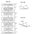
- FIG. 9A shows the latter adjustment method.
- the detection axis of the acceleration sensor is arranged substantially parallel to the optical axis of a projection lens.
- the projector is installed in a vertically not-reversed state with the optical axis set in a horizontal state.
- the optical axis of the projector is set to an allowable maximum installation angle ⁇ m relative to the horizontal.
- the obtained Og offset and sensitivity are stored in a memory within the projector.
- the automatic trapezoid (distortion) correction can be accurately performed on the projected image by using the calculated angle.
- Fig. 10A shows the relationship between the optical axis of the projection lens and the detection axis of the acceleration sensor when the projector is horizontally installed in the vertically not-reversed state.
- Fig. 10B shows the acceleration sensor output Vout_n0 in the above condition.
- the detection axis of the acceleration sensor is inclined by ⁇ G 0 relative to the optical axis of the projection lens.
- the acceleration sensor output Vout_n0 is adjusted to be equal to an output that is obtained when the projector is in an actual horizontal state, taking into account a variation in the "Og offset" output of the acceleration sensor and an error output caused by the mounting error.
- Fig. 10C shows the relationship between the optical axis of the projection lens and the detection axis of the acceleration sensor when the projector is horizontally installed in the vertically reversed state after the above-described adjustment.
- Fig. 10D shows the acceleration sensor output Vout_r0 in the above condition.
- the present invention provides a projection display apparatus which can accurately perform trapezoid correction regardless of the installed state of the projection display apparatus.
- the present invention in its primary aspect provides a projection display apparatus as specified in claim 1.
- Fig. 1 is a block diagram of a projector according to a first embodiment.
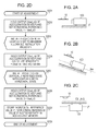
- Figs. 2A-2C illustrate respective installed states of the projector corresponding to adjustment steps
- Fig. 2D is a flowchart showing the adjustment steps executed in the first embodiment.
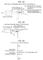
- Figs. 3A and 3B illustrate the installed states of the projector corresponding to Figs. 2A and 2C
- Fig. 3C illustrates outputs of an acceleration sensor in the first embodiment.
- Fig. 4 is a flowchart showing a processing flow executed in the first embodiment.
- Fig. 5 is a block diagram of a projector according to a second embodiment.
- Fig. 6 is a flowchart showing adjustment steps executed in the second embodiment.
- Figs. 7A and 7B illustrate the relationship between an acceleration sensor and an inclination angle.
- Fig. 8 illustrates output examples of the acceleration sensor.
- Fig. 9A is a flowchart showing a known adjustment method
- Figs. 9B and 9C illustrate installed states of the acceleration sensor.
- Figs. 10A-10D are illustrations for explaining an error of a detected angle caused when the acceleration sensor is installed in a vertically reversed state.
- Fig. 1 is a block diagram of a projector (projection display apparatus) according to a first embodiment.
- a video (image) input circuit 1 performs AD conversion of an analog video input signal 21 and outputs a digital image signal in a predetermined format.
- the output digital image signal is input to a digital signal processing circuit 2 and is subjected to a resolution conversion process, a frame rate conversion process, and a trapezoid correction process depending on a correction value "Keystone".
- An output signal of the digital signal processing circuit 2 is input to a display drive circuit 3.
- the display drive circuit 3 generates a drive signal for a display panel (liquid crystal display panel) 4, i.e., a display unit, and it outputs the drive signal to the display panel 4.
- the display panel 4 generates an image in accordance with the signal from the display drive circuit 3.
- the display drive circuit 3 has the function of generating a control signal to control the write sequence of the image signal into the display panel 4, and of generating timing pulses.
- the display drive circuit 3 is able to switch over normal display and reversed display in accordance with a control signal "UD" from a controller 8.
- the controller 8 comprises a microcomputer, etc., and executes normal/reversed display control in accordance with the control signal "UD", control for the trapezoid correction process depending on the correction value "Keystone”, etc. in the digital signal processing circuit 2 and the display drive circuit 3.
- the digital signal processing circuit 2, the display drive circuit 3, and the controller 8 constitute a control unit for controlling the image generated by the display panel 4.
- a projection lens 5 serving as a projection unit has the function of focusing the image generated by the display panel 4 on a screen.
- the projection lens 5 has the zoom function, and a zoom encoder 9 for detecting a zooming position is associated with the projection lens 5.
- An acceleration sensor (detection unit) 10 issues an output that is changed depending on an inclination angle of the projector.
- Memories 11 and 12 store respectively a horizontal reference value 1 and a horizontal reference value 2, which serves as horizontal reference data when the acceleration sensor 10 is installed in a vertically not-reversed state and a vertically reversed state.
- a selector 13 selects one of the horizontal reference data 1 and 2.
- An angle calculation unit 14 calculates an angle from both the horizontal reference value selected by the selector 13 and the detected value from the acceleration sensor 10.
- An operation switch 15 is operated by a user to switch over display in the case of floor standing installation (corresponding to the vertically not-reversed state) and display in the case of hanging installation from the ceiling (corresponding to the vertically reversed state).
- the operation switch 15 is, for example, a control button provided on a projector body, or a remote controller.
- the controller 8, the angle calculation unit 14, and the selector 13 are constituted by, e.g., an MPU, and memories 11 and 12 storing the horizontal reference data 1 and 2 are constituted by, e.g., nonvolatile memories.
- Fig. 2 shows an outline of the adjustment process flow.
- the optical axis of the projector is set to an allowable maximum installation angle ⁇ m relative to the horizontal.
- Figs. 3A and 3B illustrate the states, shown in Figs. 2A and 2C, in more detail, respectively.
- Fig. 3C illustrates output signals from the acceleration sensor 10 in the states shown in Figs. 3A and 3B.
- an inclination of the detection axis of the acceleration sensor relative to the horizontal is assumed to be ⁇ G 0
- an inclination of the optical axis of the projection lens is assumed to be ⁇ L 0
- horizontal reference value 2 - horizontal reference value 1 sin 2 ⁇ ⁇ ⁇ G 0 - ⁇ ⁇ L 0
- the projector body may be installed in the horizontal state instead of setting the optical axis of the projection lens 5 in the horizontal state. In such a case, however, there remains a minute error (corresponding to ⁇ L 0 ) resulting from deviation of the optical axis of the projection lens from the horizontal when the projector body is installed in the horizontal state.
- Fig. 4 is a flowchart showing the automatic trapezoid correction process.
- the controller 8 as a part of the MPU obtains, in accordance with an instruction from the operation switch 15, information indicating whether an image is displayed in a normal state or in a vertically reversed state. Based on the obtained information, the controller 8 determines the display direction (i.e., normal display or vertically reversed display of the image) set for the display panel 4.
- the display direction i.e., normal display or vertically reversed display of the image
- the normal display When the projector is installed in the floor standing state (ordinary installation), the normal display is selected, and when it is installed in the hanging state from the ceiling, the vertically reversed display is displayed.
- the horizontal reference value the horizontal reference value 1 is set by the selector 13 as a part of the MPU.
- the horizontal reference value the horizontal reference value 2 is set by the selector 13.
- f(x,y) represents the function including the inclination angle and the zooming position as arguments and is decided depending on optical characteristics of the projection lens, etc.
- Keystone represents a rate at which the digital signal processing circuit 2 executes geometrical correction (trapezoid correction) in a digital manner.
- the controller 8 transmits the digital distortion correction factor Keystone to the digital signal processing circuit 2, and the digital signal processing circuit 2 executes the trapezoid correction in a digital manner on the image generated by the display panel 4.
- Fig. 5 is a block diagram of a projector according to a second embodiment.
- the second embodiment differs from the first embodiment in that a vertical reversal sensor 20 for automatically detecting the installation of the projector in the vertically reversed state is disposed instead of the vertically reversing operation switch 15.
- the other components are the same as those in the first embodiment and a description thereof is not repeated here.
- the vertical reversal sensor 20 can be constituted as a mechanical switch for detecting the installation of the projector in the vertically reversed state, or an acceleration sensor.
- the acceleration sensor 10 can also be used as such an acceleration sensor if the former is prepared as an acceleration sensor having two or more detection axes.
- a method of obtaining the horizontal reference value 1 and the horizontal reference value 2 and performing an adjustment is the same as that described above in the first embodiment.
- Fig. 6 is a flowchart showing the automatic trapezoid correction process.
- the controller 8 as a part of the MPU obtains, from the vertical reversal sensor 20, information indicating whether the projector is installed in the vertically reversed state or not. Based on the obtained information, the controller 8 determines the installed state of the projector. Stated another way, the controller 8 and the vertical reversal sensor 20 operate as a determination unit for determining the installed state of the projector.
Landscapes
- Engineering & Computer Science (AREA)
- Multimedia (AREA)
- Signal Processing (AREA)
- Physics & Mathematics (AREA)
- Geometry (AREA)
- Transforming Electric Information Into Light Information (AREA)
- Projection Apparatus (AREA)
Abstract
Description
- The present invention relates to a projection display apparatus.
- When an image is projected by a projector (projection display apparatus) onto a screen in an oblique direction, the projected image is deformed into a trapezoidal shape. This phenomenon is called a trapezoid distortion or Keystone distortion. In order to correct the trapezoid distortion, a projector with the so-called digital Keystone correction function of changing the form of the projected image through digital image signal processing has already been commercialized. In a product having that function, a Keystone correction input amount is usually decided in a manual manner.
- Also, an image projection apparatus is proposed which includes an inclination sensor in a projector body and automatically corrects the trapezoid distortion depending on the detected inclination angle (see Patent Document 1:
Japanese Patent Laid-Open No. 2001-186538
For example, an acceleration sensor is employed as the inclination sensor. - Figs. 7A and 7B show the principle for calculating the inclination angle by the acceleration sensor. The detection axis of the acceleration sensor is assumed to be parallel to an optical axis.
- In Fig. 7A,
reference numeral 10 denotes an acceleration sensor, and 100 denotes a projector. - The
projector 100 is horizontally installed in Fig. 7A. Therefore, a gravity component does not occur in the direction of the detection axis, and the output of theacceleration sensor 10 shows 0 [g] (g represents the acceleration of gravity). - On the other hand, in Fig. 7B, the projector is installed in a state inclined by θ [degree] relative to the horizontal. In this case, the acceleration sensor output shows sinθ [g].
- Accordingly, the inclination angle can be detected by calculating arcsine (sin-1) of the acceleration sensor output.
- Fig. 8 illustrates one example of the acceleration sensor output.
- The acceleration sensor output is detected in the form of an analog voltage output or a DUTY output. The number of detection axes ranges from one to three. Herein, a 1-axis analog voltage output is described as an example because it is relatively inexpensive to practice.
- The acceleration sensor outputs a voltage in proportion to the detected acceleration (i.e., Vout_mlg [V] at -90 degrees, Vout_0g [V] at the horizontal, and Vout_plg [V] at +90 degrees).
- (Vout_0g - Vout_mlg) or (Vout_plg - Vout_0g) is called "sensitivity" and represents an output voltage per 1 [g].
- Also, Vout_0g is called "Og offset" and represents the output of the acceleration sensor at 0 [g] (= horizontal).
- The acceleration sensor is constituted by a semiconductor in many cases, and "sensitivity" and "Og offset" have variations depending on individual parts.
- Further, variations may occur in accuracy in mounting inclination of the acceleration sensor, accuracy in substrate mounting, etc. Therefore, acceleration sensors are desired to be adjusted individually.
- In particular, a variation in the Og offset greatly affects the automatic trapezoid correction function that is often used near 0 degree of the inclination angle.
- Thus, projectors have to be individually adjusted in order to realize angle detection with high accuracy by using acceleration sensors.
- Adjustment of individual acceleration sensors are generally performed by a method of experimentally measuring the relationship between the acceleration sensor output and angle with respect to a plurality of angles (see Patent Document 2:
Japanese Patent Laid-Open No. 2004-334116 - A flowchart of Fig. 9A shows the latter adjustment method.
- It is assumed that the detection axis of the acceleration sensor is arranged substantially parallel to the optical axis of a projection lens.
- First, the adjustment is started in S101.
- In S102, the projector is installed in a vertically not-reversed state with the optical axis set in a horizontal state.
- In S103, the acceleration sensor output (Vout_0) in the above state is stored in a storage unit. Namely:
Og offset = Vout_0 - In S104, the optical axis of the projector is set to an allowable maximum installation angle θm relative to the horizontal.
- In S105, the acceleration sensor output (Vout_m) in the maximally inclined state is stored. Further, the sensitivity is calculated based on the following formula:

- In S106, the obtained Og offset and sensitivity are stored in a memory within the projector.
- In S107, the adjustment is brought to an end.
- The relationship between the output of the acceleration sensor and the acceleration of gravity is linear. Accordingly, if the output of the acceleration sensor is Vout at an arbitrary inclination angle θ, the inclination angle θ is calculated by:


- The automatic trapezoid (distortion) correction can be accurately performed on the projected image by using the calculated angle.
- In practice, however, when the projector is used in the vertically reversed state, it is sometimes used in a state hanging from the ceiling. When the projector is used in such a way, the trapezoid correction cannot be accurately performed in some cases just by using the above-described adjustment method. The reason will be described below with reference to Figs. 10A-10D.
- Fig. 10A shows the relationship between the optical axis of the projection lens and the detection axis of the acceleration sensor when the projector is horizontally installed in the vertically not-reversed state.
- Fig. 10B shows the acceleration sensor output Vout_n0 in the above condition. In the illustrated example, the detection axis of the acceleration sensor is inclined by θG0 relative to the optical axis of the projection lens.
- The acceleration sensor output Vout_n0 is adjusted to be equal to an output that is obtained when the projector is in an actual horizontal state, taking into account a variation in the "Og offset" output of the acceleration sensor and an error output caused by the mounting error.
- Fig. 10C shows the relationship between the optical axis of the projection lens and the detection axis of the acceleration sensor when the projector is horizontally installed in the vertically reversed state after the above-described adjustment.
- Fig. 10D shows the acceleration sensor output Vout_r0 in the above condition.
- Because the projector is horizontally installed in both the vertically not-reversed state and the vertically reversed state, Vout_n0 = Vout_r0 should be resulted if the optical axis of the projection lens and the detection axis of the acceleration sensor are parallel to each other (i.e., θG0 = 0). In fact, however, an error of:

- The present invention provides a projection display apparatus which can accurately perform trapezoid correction regardless of the installed state of the projection display apparatus.
- The present invention in its primary aspect provides a projection display apparatus as specified in
claim 1. - Further features of the present invention will become apparent from the following description of exemplary embodiments with reference to the attached drawings.
- Fig. 1 is a block diagram of a projector according to a first embodiment.
- Figs. 2A-2C illustrate respective installed states of the projector corresponding to adjustment steps, and Fig. 2D is a flowchart showing the adjustment steps executed in the first embodiment.
- Figs. 3A and 3B illustrate the installed states of the projector corresponding to Figs. 2A and 2C, and Fig. 3C illustrates outputs of an acceleration sensor in the first embodiment.
- Fig. 4 is a flowchart showing a processing flow executed in the first embodiment.
- Fig. 5 is a block diagram of a projector according to a second embodiment.
- Fig. 6 is a flowchart showing adjustment steps executed in the second embodiment.
- Figs. 7A and 7B illustrate the relationship between an acceleration sensor and an inclination angle.
- Fig. 8 illustrates output examples of the acceleration sensor.
- Fig. 9A is a flowchart showing a known adjustment method, and Figs. 9B and 9C illustrate installed states of the acceleration sensor.
- Figs. 10A-10D are illustrations for explaining an error of a detected angle caused when the acceleration sensor is installed in a vertically reversed state.
- Projection display apparatuses according to embodiments of the present invention will be described in detail below with reference to the accompanying drawings. First Embodiment
- Fig. 1 is a block diagram of a projector (projection display apparatus) according to a first embodiment.
- A video (image)
input circuit 1 performs AD conversion of an analogvideo input signal 21 and outputs a digital image signal in a predetermined format. The output digital image signal is input to a digitalsignal processing circuit 2 and is subjected to a resolution conversion process, a frame rate conversion process, and a trapezoid correction process depending on a correction value "Keystone". - An output signal of the digital
signal processing circuit 2 is input to adisplay drive circuit 3. Thedisplay drive circuit 3 generates a drive signal for a display panel (liquid crystal display panel) 4, i.e., a display unit, and it outputs the drive signal to thedisplay panel 4. Thedisplay panel 4 generates an image in accordance with the signal from thedisplay drive circuit 3. - Also, the
display drive circuit 3 has the function of generating a control signal to control the write sequence of the image signal into thedisplay panel 4, and of generating timing pulses. - The
display drive circuit 3 is able to switch over normal display and reversed display in accordance with a control signal "UD" from acontroller 8. - The
controller 8 comprises a microcomputer, etc., and executes normal/reversed display control in accordance with the control signal "UD", control for the trapezoid correction process depending on the correction value "Keystone", etc. in the digitalsignal processing circuit 2 and thedisplay drive circuit 3. The digitalsignal processing circuit 2, thedisplay drive circuit 3, and thecontroller 8 constitute a control unit for controlling the image generated by thedisplay panel 4. - A
projection lens 5 serving as a projection unit has the function of focusing the image generated by thedisplay panel 4 on a screen. - Also, the
projection lens 5 has the zoom function, and azoom encoder 9 for detecting a zooming position is associated with theprojection lens 5. - An acceleration sensor (detection unit) 10 issues an output that is changed depending on an inclination angle of the projector.
Memories horizontal reference value 1 and ahorizontal reference value 2, which serves as horizontal reference data when theacceleration sensor 10 is installed in a vertically not-reversed state and a vertically reversed state. Aselector 13 selects one of thehorizontal reference data - An
angle calculation unit 14 calculates an angle from both the horizontal reference value selected by theselector 13 and the detected value from theacceleration sensor 10. - An
operation switch 15 is operated by a user to switch over display in the case of floor standing installation (corresponding to the vertically not-reversed state) and display in the case of hanging installation from the ceiling (corresponding to the vertically reversed state). Theoperation switch 15 is, for example, a control button provided on a projector body, or a remote controller. - Generally, the
controller 8, theangle calculation unit 14, and theselector 13 are constituted by, e.g., an MPU, andmemories horizontal reference data - A method of calculating the angle from the detected value of the
acceleration sensor 10 and thehorizontal reference values - A method of obtaining the
horizontal reference value 1 and thehorizontal reference value 2, i.e., an adjustment method, is now described. - Fig. 2 shows an outline of the adjustment process flow.
- First, the adjustment is started in S201.
- In S202, as shown in Fig. 2A, the projector is installed in the vertically not-reversed state with the optical axis of the projection lens set in the horizontal state. A value corresponding to the output of the acceleration sensor at that time is set as the horizontal reference value 1:
horizontal reference value 1 = Vout_n0 - In S203, as shown in Fig. 2B, the optical axis of the projector is set to an allowable maximum installation angle θm relative to the horizontal.
- In S204, the acceleration sensor output (Vout_m) in the maximally inclined state is held, and the sensitivity is calculated based on the following formula:

- In S205, as shown in Fig. 2C, the projector is installed in the vertically reversed state with the optical axis of the projection lens set in the horizontal state.
- In S206, the output (Vout_r0) of the acceleration sensor in the vertically reversed state is set as the horizontal reference value 2:
horizontal reference value 2 = Vout_r0 - In S207, the above-mentioned "
horizontal reference value 1" and "horizontal reference value 2" are stored in thememories controller 8. - In S208, the adjustment is brought to an end.
- Figs. 3A and 3B illustrate the states, shown in Figs. 2A and 2C, in more detail, respectively.
- Fig. 3C illustrates output signals from the
acceleration sensor 10 in the states shown in Figs. 3A and 3B. - Herein, an inclination of the detection axis of the acceleration sensor relative to the horizontal is assumed to be θG0, and an inclination of the optical axis of the projection lens is assumed to be θL0. In this case, horizontal reference value 2 -
horizontal reference 
- In S202 and S205 of Fig. 2D, the projector body may be installed in the horizontal state instead of setting the optical axis of the
projection lens 5 in the horizontal state. In such a case, however, there remains a minute error (corresponding to θL0) resulting from deviation of the optical axis of the projection lens from the horizontal when the projector body is installed in the horizontal state. - The flow of the automatic trapezoid correction process executed in the thus-constructed system will be described below.
- Fig. 4 is a flowchart showing the automatic trapezoid correction process.
- In S401, the automatic trapezoid correction process is started.
- In S402, the MPU including the
controller 8, theangle calculation unit 14, theselector 13, etc. reads the output (= Vout) of theacceleration sensor 10. - Simultaneously, the MPU also reads the output (= ZmPos) of the
zoom encoder 9 at that time. - In S403, the
controller 8 as a part of the MPU obtains, in accordance with an instruction from theoperation switch 15, information indicating whether an image is displayed in a normal state or in a vertically reversed state. Based on the obtained information, thecontroller 8 determines the display direction (i.e., normal display or vertically reversed display of the image) set for thedisplay panel 4. - When the projector is installed in the floor standing state (ordinary installation), the normal display is selected, and when it is installed in the hanging state from the ceiling, the vertically reversed display is displayed.
- In S404, in the case of the normal display, the horizontal reference value = the
horizontal reference value 1 is set by theselector 13 as a part of the MPU. - In S405, in the case of the vertically reversed display, the horizontal reference value = the
horizontal reference value 2 is set by theselector 13. - In S406, the
angle calculation unit 14 as a part of the MPU calculates the inclination angle θ based on the output Vout of the acceleration sensor and the horizontal reference value selected by theselector 13 from the following formula:
- In S407, the
controller 8 as a part of the MPU calculates a digital distortion correction factor Keystone based on the inclination angle θ and the zooming position ZmPos by using a predetermined formula given below:
Keystone = f(θ, ZmPos) - Herein, f(x,y) represents the function including the inclination angle and the zooming position as arguments and is decided depending on optical characteristics of the projection lens, etc.
- Keystone represents a rate at which the digital
signal processing circuit 2 executes geometrical correction (trapezoid correction) in a digital manner. - In S408, the
controller 8 transmits the digital distortion correction factor Keystone to the digitalsignal processing circuit 2, and the digitalsignal processing circuit 2 executes the trapezoid correction in a digital manner on the image generated by thedisplay panel 4. - Fig. 5 is a block diagram of a projector according to a second embodiment.
- The second embodiment differs from the first embodiment in that a
vertical reversal sensor 20 for automatically detecting the installation of the projector in the vertically reversed state is disposed instead of the vertically reversingoperation switch 15. The other components are the same as those in the first embodiment and a description thereof is not repeated here. - The
vertical reversal sensor 20 can be constituted as a mechanical switch for detecting the installation of the projector in the vertically reversed state, or an acceleration sensor. - When the
vertical reversal sensor 20 is constituted as an acceleration sensor, theacceleration sensor 10 can also be used as such an acceleration sensor if the former is prepared as an acceleration sensor having two or more detection axes. A method of obtaining thehorizontal reference value 1 and thehorizontal reference value 2 and performing an adjustment is the same as that described above in the first embodiment. - The flow of the automatic trapezoid correction process executed in the thus-constructed system will be described below.
- Fig. 6 is a flowchart showing the automatic trapezoid correction process.
- In S601, the automatic trapezoid correction process is started.
- In S602, the MPU reads the output (= Vout) of the
acceleration sensor 10. - Simultaneously, the MPU also reads the output (= ZmPos) of the
zoom encoder 9 at that time. - In S603, the
controller 8 as a part of the MPU obtains, from thevertical reversal sensor 20, information indicating whether the projector is installed in the vertically reversed state or not. Based on the obtained information, thecontroller 8 determines the installed state of the projector. Stated another way, thecontroller 8 and thevertical reversal sensor 20 operate as a determination unit for determining the installed state of the projector. - When the information indicating the vertically reversed installation is obtained from the
acceleration sensor 10, whether the projector is installed in the vertically reversed state or not is determined from an output of theacceleration sensor 10 with respect to an axis other than the axis used to detect the inclination angle. - Subsequent steps are the same as those in the flowchart of Fig. 4 and a description thereof is omitted here.
- While the present invention has been described with reference to exemplary embodiments, it is to be understood that the invention is not limited to the disclosed exemplary embodiments. The scope of the following claims is to be accorded the broadest interpretation so as to encompass all modifications, equivalent structures and functions.
Claims (4)
- A projection display apparatus including:a display unit (4) adapted to generate an image;a projection unit (5) adapted to project the image generated by the display unit;a control unit (2, 3, 8) adapted to control the image generated by the display unit;a detection unit (10) adapted to issue an output changed depending on an inclination angle of the projection display apparatus; anda storage unit (11, 12) adapted to store a plurality of horizontal reference values corresponding to installed states of the projection display apparatus,wherein the control unit is arranged to change the image generated by the display unit in accordance with an output of the detection unit and one horizontal reference value selected from among the plurality of horizontal reference values.
- A projection display apparatus according to Claim 1, wherein the plurality of horizontal reference values include a first horizontal reference value obtained when the projection display apparatus is installed in a first state, and a second horizontal reference value obtained when the projection display apparatus is installed in a second state which is vertically reversed from the first state.
- A projection display apparatus according to Claim 1, further comprising:a switch (15) adapted to determine the orientation of top and bottom sides of the image generated by the display unit (4) based on the orientation of the projection display apparatus,wherein the horizontal reference value to be selected is determined in accordance with an instruction from the switch.
- A projection display apparatus according to Claim 1, further comprising:a determination unit (8, 20) adapted to determine the installed state of the projection display apparatus,wherein the horizontal reference value to be selected is determined in accordance with a determination result of the determination unit.
Applications Claiming Priority (1)
| Application Number | Priority Date | Filing Date | Title |
|---|---|---|---|
| JP2006031047 | 2006-02-08 |
Publications (2)
| Publication Number | Publication Date |
|---|---|
| EP1819157A2 true EP1819157A2 (en) | 2007-08-15 |
| EP1819157A3 EP1819157A3 (en) | 2009-01-07 |
Family
ID=37963842
Family Applications (1)
| Application Number | Title | Priority Date | Filing Date |
|---|---|---|---|
| EP07101924A Withdrawn EP1819157A3 (en) | 2006-02-08 | 2007-02-07 | Projection display apparatus |
Country Status (3)
| Country | Link |
|---|---|
| US (2) | US20070182936A1 (en) |
| EP (1) | EP1819157A3 (en) |
| CN (2) | CN101017313B (en) |
Families Citing this family (10)
| Publication number | Priority date | Publication date | Assignee | Title |
|---|---|---|---|---|
| JP5436884B2 (en) * | 2009-02-25 | 2014-03-05 | 京セラ株式会社 | Portable electronic devices |
| JP5907404B2 (en) * | 2011-03-15 | 2016-04-26 | 株式会社リコー | Image projection device |
| JP5891714B2 (en) * | 2011-11-02 | 2016-03-23 | 株式会社リコー | Projector and trapezoidal distortion correction method |
| JP6304740B2 (en) * | 2013-11-01 | 2018-04-04 | Necディスプレイソリューションズ株式会社 | Attitude detection apparatus, control method therefor, and projector |
| US12401911B2 (en) | 2014-11-07 | 2025-08-26 | Duelight Llc | Systems and methods for generating a high-dynamic range (HDR) pixel stream |
| US12401912B2 (en) | 2014-11-17 | 2025-08-26 | Duelight Llc | System and method for generating a digital image |
| CN104683724B (en) * | 2015-03-03 | 2019-01-18 | 苏州佳世达光电有限公司 | Projection arrangement and its bearing calibration |
| US12445736B2 (en) | 2015-05-01 | 2025-10-14 | Duelight Llc | Systems and methods for generating a digital image |
| JP7019064B2 (en) * | 2018-09-10 | 2022-02-14 | 三菱電機株式会社 | Camera installation support device and method, installation angle calculation method, program and recording medium |
| US11783449B2 (en) * | 2021-12-09 | 2023-10-10 | Htc Corporation | Method for adjusting displayed content based on host posture, host, and computer readable storage medium |
Citations (2)
| Publication number | Priority date | Publication date | Assignee | Title |
|---|---|---|---|---|
| JP2003005278A (en) | 2001-06-20 | 2003-01-08 | Fujitsu General Ltd | LCD projector |
| JP2004334116A (en) * | 2003-05-12 | 2004-11-25 | Sanyo Electric Co Ltd | Method for calculating elevation angle of liquid crystal projector |
Family Cites Families (19)
| Publication number | Priority date | Publication date | Assignee | Title |
|---|---|---|---|---|
| KR100188218B1 (en) * | 1995-11-13 | 1999-06-01 | 전주범 | Asymmetric picture compensating control method for projector |
| JP3509652B2 (en) * | 1999-08-23 | 2004-03-22 | 日本電気株式会社 | Projector device |
| WO2001048551A1 (en) * | 1999-12-24 | 2001-07-05 | Matsushita Electric Industrial Co., Ltd. | Projector |
| US6520647B2 (en) * | 2000-08-17 | 2003-02-18 | Mitsubishi Electric Research Laboratories Inc. | Automatic keystone correction for projectors with arbitrary orientation |
| TW480362B (en) * | 2000-09-14 | 2002-03-21 | Delta Electronics Inc | Automatic calibration method and device of the projector display |
| JP2003153135A (en) * | 2001-11-16 | 2003-05-23 | Sanyo Electric Co Ltd | Projection display device |
| JP3680807B2 (en) * | 2002-03-20 | 2005-08-10 | セイコーエプソン株式会社 | Projector to correct keystone distortion |
| US6974217B2 (en) * | 2002-03-20 | 2005-12-13 | Seiko Epson Corporation | Projector executing keystone correction |
| US6877863B2 (en) * | 2002-06-12 | 2005-04-12 | Silicon Optix Inc. | Automatic keystone correction system and method |
| JP4155890B2 (en) * | 2003-07-15 | 2008-09-24 | カシオ計算機株式会社 | Projector, projector tilt angle acquisition method, and projection image correction method |
| JP3969363B2 (en) * | 2003-07-30 | 2007-09-05 | カシオ計算機株式会社 | Projector and projection image correction method for projector |
| US7150536B2 (en) * | 2003-08-08 | 2006-12-19 | Casio Computer Co., Ltd. | Projector and projection image correction method thereof |
| JP4037816B2 (en) * | 2003-10-06 | 2008-01-23 | Necディスプレイソリューションズ株式会社 | Projector and method of projecting screen by projector |
| JP3770609B2 (en) * | 2003-10-14 | 2006-04-26 | Necビューテクノロジー株式会社 | Projector and distortion correction method |
| JP2005227661A (en) * | 2004-02-16 | 2005-08-25 | Nec Viewtechnology Ltd | Projector and method of correcting distortion |
| JP3960390B2 (en) * | 2004-05-31 | 2007-08-15 | Necディスプレイソリューションズ株式会社 | Projector with trapezoidal distortion correction device |
| JP2006091610A (en) * | 2004-09-27 | 2006-04-06 | Sanyo Electric Co Ltd | Projection type video display device |
| JP4169027B2 (en) * | 2005-09-27 | 2008-10-22 | カシオ計算機株式会社 | Ranging device and ranging method |
| US7658498B2 (en) * | 2006-07-13 | 2010-02-09 | Dell Products, Inc. | System and method for automated display orientation detection and compensation |
-
2007
- 2007-02-05 US US11/671,114 patent/US20070182936A1/en not_active Abandoned
- 2007-02-07 EP EP07101924A patent/EP1819157A3/en not_active Withdrawn
- 2007-02-08 CN CN2007100054232A patent/CN101017313B/en not_active Expired - Fee Related
- 2007-02-08 CN CN201110243912.8A patent/CN102290042B/en not_active Expired - Fee Related
-
2011
- 2011-08-15 US US13/210,118 patent/US8836869B2/en not_active Expired - Fee Related
Patent Citations (2)
| Publication number | Priority date | Publication date | Assignee | Title |
|---|---|---|---|---|
| JP2003005278A (en) | 2001-06-20 | 2003-01-08 | Fujitsu General Ltd | LCD projector |
| JP2004334116A (en) * | 2003-05-12 | 2004-11-25 | Sanyo Electric Co Ltd | Method for calculating elevation angle of liquid crystal projector |
Non-Patent Citations (1)
| Title |
|---|
| MICHELLE CLIFFORD ET AL: "Freescale Semiconductor Application Note Measuring Tilt with Low-g Accelerometers", 1 May 2005 (2005-05-01), XP055329980, Retrieved from the Internet <URL:http://www.nxp.com/assets/documents/data/en/application-notes/AN3107.pdf> [retrieved on 20161216] * |
Also Published As
| Publication number | Publication date |
|---|---|
| US20110298828A1 (en) | 2011-12-08 |
| CN102290042B (en) | 2014-10-15 |
| EP1819157A3 (en) | 2009-01-07 |
| CN102290042A (en) | 2011-12-21 |
| CN101017313B (en) | 2011-10-12 |
| CN101017313A (en) | 2007-08-15 |
| US20070182936A1 (en) | 2007-08-09 |
| US8836869B2 (en) | 2014-09-16 |
Similar Documents
| Publication | Publication Date | Title |
|---|---|---|
| EP1819157A2 (en) | Projection display apparatus | |
| US7286164B2 (en) | Method of and unit for inputting an image, and computer product | |
| EP0689353B1 (en) | Display method and apparatus | |
| US8390733B2 (en) | Imaging device with interchangeable lens and camera body for imaging device | |
| US7252388B2 (en) | Projector with tilt-angle detecting capability | |
| US7609458B2 (en) | Projection apparatus, elevation angle control method therefor and recording medium | |
| US8011789B2 (en) | Rear projection display | |
| US20070046902A1 (en) | Projector device | |
| CN101674414A (en) | Image pickup apparatus | |
| JP4468389B2 (en) | Projection display | |
| JP4169027B2 (en) | Ranging device and ranging method | |
| JP2007093245A (en) | Ranging device and ranging method | |
| JP4497900B2 (en) | Image projection apparatus and image projection system having the same | |
| JP4803972B2 (en) | Image projection device | |
| CN100489639C (en) | Image blur correction device | |
| JP2006080837A (en) | Imaging device | |
| JP2004363856A (en) | Projection display device | |
| KR20090072038A (en) | Mobile robot with projector and its project method | |
| JP4756939B2 (en) | projector | |
| JP4653043B2 (en) | Imaging apparatus and control method thereof | |
| JP2007019654A (en) | projector | |
| JP2005295328A (en) | Distortion correction method and projector | |
| JP3709405B2 (en) | Projector having tilt angle measuring device | |
| JPH1034571A (en) | Robot dislocation correcting device | |
| JP2007017537A (en) | Keystone correction method and projector |
Legal Events
| Date | Code | Title | Description |
|---|---|---|---|
| PUAI | Public reference made under article 153(3) epc to a published international application that has entered the european phase |
Free format text: ORIGINAL CODE: 0009012 |
|
| AK | Designated contracting states |
Kind code of ref document: A2 Designated state(s): AT BE BG CH CY CZ DE DK EE ES FI FR GB GR HU IE IS IT LI LT LU LV MC NL PL PT RO SE SI SK TR |
|
| AX | Request for extension of the european patent |
Extension state: AL BA HR MK YU |
|
| PUAL | Search report despatched |
Free format text: ORIGINAL CODE: 0009013 |
|
| AK | Designated contracting states |
Kind code of ref document: A3 Designated state(s): AT BE BG CH CY CZ DE DK EE ES FI FR GB GR HU IE IS IT LI LT LU LV MC NL PL PT RO SE SI SK TR |
|
| AX | Request for extension of the european patent |
Extension state: AL BA HR MK RS |
|
| RIC1 | Information provided on ipc code assigned before grant |
Ipc: H04N 9/31 20060101AFI20081128BHEP |
|
| 17P | Request for examination filed |
Effective date: 20090707 |
|
| AKX | Designation fees paid |
Designated state(s): AT BE BG CH CY CZ DE DK EE ES FI FR GB GR HU IE IS IT LI LT LU LV MC NL PL PT RO SE SI SK TR |
|
| 17Q | First examination report despatched |
Effective date: 20110318 |
|
| STAA | Information on the status of an ep patent application or granted ep patent |
Free format text: STATUS: THE APPLICATION HAS BEEN WITHDRAWN |
|
| 18W | Application withdrawn |
Effective date: 20170411 |