EP1819071A1 - Method of delaying an optical signal and optical routing device - Google Patents
Method of delaying an optical signal and optical routing device Download PDFInfo
- Publication number
- EP1819071A1 EP1819071A1 EP06290264A EP06290264A EP1819071A1 EP 1819071 A1 EP1819071 A1 EP 1819071A1 EP 06290264 A EP06290264 A EP 06290264A EP 06290264 A EP06290264 A EP 06290264A EP 1819071 A1 EP1819071 A1 EP 1819071A1
- Authority
- EP
- European Patent Office
- Prior art keywords
- optical
- fibre
- dispersion
- delay line
- wavelength
- Prior art date
- Legal status (The legal status is an assumption and is not a legal conclusion. Google has not performed a legal analysis and makes no representation as to the accuracy of the status listed.)
- Withdrawn
Links
- 230000003287 optical effect Effects 0.000 title claims abstract description 70
- 238000000034 method Methods 0.000 title claims description 6
- 239000006185 dispersion Substances 0.000 claims abstract description 75
- 239000013307 optical fiber Substances 0.000 claims abstract description 41
- 239000000835 fiber Substances 0.000 claims abstract description 25
- 230000004044 response Effects 0.000 claims abstract description 20
- 230000007704 transition Effects 0.000 claims description 6
- 230000000295 complement effect Effects 0.000 claims description 5
- 230000003111 delayed effect Effects 0.000 claims description 5
- 230000001419 dependent effect Effects 0.000 claims description 5
- 230000000737 periodic effect Effects 0.000 abstract description 7
- 230000000694 effects Effects 0.000 description 11
- 238000010586 diagram Methods 0.000 description 8
- 230000003595 spectral effect Effects 0.000 description 5
- 230000008859 change Effects 0.000 description 2
- 239000000463 material Substances 0.000 description 2
- 238000005259 measurement Methods 0.000 description 2
- 230000009471 action Effects 0.000 description 1
- 230000005540 biological transmission Effects 0.000 description 1
- 230000002301 combined effect Effects 0.000 description 1
- 238000002310 reflectometry Methods 0.000 description 1
Images
Classifications
-
- H—ELECTRICITY
- H04—ELECTRIC COMMUNICATION TECHNIQUE
- H04B—TRANSMISSION
- H04B10/00—Transmission systems employing electromagnetic waves other than radio-waves, e.g. infrared, visible or ultraviolet light, or employing corpuscular radiation, e.g. quantum communication
- H04B10/25—Arrangements specific to fibre transmission
- H04B10/2507—Arrangements specific to fibre transmission for the reduction or elimination of distortion or dispersion
- H04B10/2513—Arrangements specific to fibre transmission for the reduction or elimination of distortion or dispersion due to chromatic dispersion
- H04B10/25133—Arrangements specific to fibre transmission for the reduction or elimination of distortion or dispersion due to chromatic dispersion including a lumped electrical or optical dispersion compensator
Definitions
- the present invention relates to a method of delaying an optical signal, wherein light emitted by a wavelength-tuneable laser is transmitted on a fibre link having a predetermined amount of chromatic dispersion.
- the present invention also relates to an optical delay line comprising a wavelength-tuneable laser and a span of optical fibre connected with said laser, said fibre having a predetermined amount of chromatic dispersion.
- the present invention relates to an optical routing device comprising an optical switch.
- Optical delay lines of the above-mentioned type are required for applications such as optical routers operating at data rates of, for instance, 10 or 40 Gbit/s, wherein an optical switching means is used to route data contents, e.g. in the form of data packets, in accordance with a time delay introduced by the chromatic dispersion effect of the optical fibre link.
- a desired characteristic of such optical delay lines is a large dynamic, preferably of several hundreds of picoseconds (ps).
- ps picoseconds
- a common approach for to devise an optical delay line consists of employing moving mechanical parts, such as chirped mirrors, for generating said time delay.
- prior art solutions of this kind entail problems commonly encountered in connection with a use of rapidly moving mechanical parts.
- An alternative solution known from the prior art consists of using a wavelength-tuneable laser connected with a spool of fibre having a certain amount of chromatic dispersion.
- the data to be delayed is encoded on the laser wavelength, for instance, by means of an external modulator.
- Owing to the chromatic dispersion of the fibre material a variation of wavelengths of the laser translates into a time delay since different wavelengths experience different amounts of chromatic dispersion.
- this approach suffers from the disadvantage that large values of chromatic dispersion, which are used to obtain long delay times, and / or wide signal bandwidths lead to an unacceptable amount of distortion of a transmitted optical signal due to the effect of accumulated chromatic dispersion of the delay line.
- the object is achieved by providing a method of the above-mentioned type, wherein at least part of the chromatic dispersion introduced by the fibre is compensated by means of a phase response unit adapated to compensate at least part of the chromatic dispersion without cancelling a group delay introduced by said fibre dispersion.
- an optical delay line of the above-mentioned type in the case of an optical delay line of the above-mentioned type the object is achieved by providing said optical delay line with a phase response unit connected with said fibre span and adapted to compensate at least part of the chromatic dispersion introduced by the optical fibre without cancelling a group delay introduced by said fibre dispersion.
- the object is achieved by providing an optical routing device of the above-mentioned type which further comprises an optical delay line according to said second aspect of the present invention in operative connection with the optical switch.
- the basic idea of the present invention consists in compensating chromatic dispersion of the optical fibre used for delaying optical signals by means of a specific phase response unit functioning as a Dispersion Compensation Module (DCM) and adapated to at least partly compensate the chromatic dispersion without cancelling a group delay introduced by said fibre dispersion.
- DCM Dispersion Compensation Module
- said phase response unit may be comprise at least one Gires-Tournois interferometer.
- a Gires-Tournois interferometer basically is an optical standing-wave cavity designed to create chromatic dispersion. Contrary to Dispersion Compensating Fibre (DCF) commonly used in optical transmission systems a Gires-Tournois DCM (GT-DCM) will not annihilate the delay generated by chromatic fibre dispersion, but will only cancel the presumably negative distortion effects generated together with the desired time delay within a given periodic spectral band.
- DCF Dispersion Compensating Fibre
- GT-DCM Gires-Tournois DCM
- the phase response unit may be devised in the form of one of a Virtually Imaged Phased Array (VIPA), a ring resonator, and a fibre Bragg grating (FBG) or in the form of any other Dispersion Compensation Module adapated to compensate chromatic dispersion within separate (periodic) spectral bands without cancelling a group delay introduced by fibre dispersion.
- VIPA Virtually Imaged Phased Array
- FBG fibre Bragg grating
- the tuneable laser is further connected with an encoding means, e.g. an external modulator, adapted to encode data to be delayed on the laser wavelength.
- an encoding means e.g. an external modulator
- the optical fibre has a first constant dispersion value for to induce a linear group delay.
- a phase response unit e.g. at least one Gires-Tournois interferometer.
- the phase response unit is adapted to induce a wavelength-dependent dispersion having wavelength regions of a second dispersion value essentially complementary to a dispersion value of the optical fibre.
- the phase response unit completely compensates the dispersion effects within said wavelengths regions, hereinafter also referred to as "bandwidths", without cancelling the time delay effect induced by optical fibre dispersion.
- the phase response unit is adapted to compensate the chromatic dispersion introduced by the optical fibre within separate, preferably periodic, spectral bands.
- a group delay generated by a combined action of the optical fibre and the phase response unit is a stair-like function of the optical wavelength and presents a succession of regions with essentially constant respective group delay, which are separated by respective transition regions of steeply increasing group delay.
- the time delay induced on the transmitted optical signals is a constant value for respective bandwidths, at the wavelengths limits of which a steep transition (step) occurs with respect to an adjacent bandwidth.
- the tuneable laser can be tuned to optical wavelengths comprised within a given bandwidth for to transmit data which will share a common delay time when arriving at an optical switching means of a routing device comprising the inventive delay line. Tuning the laser to wavelengths comprised within a different bandwidth will result in a time delay which differs by at least said step value from the time delay of other bandwidth wavelengths, as mentioned farther up.
- the present invention provides an optical delay line having a large dynamic without relying on moving mechanical parts and without suffering from the negative effects of signal distortion.
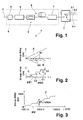
- Fig. 1 shows a schematic block diagram of an optical routing device 1 in accordance with an aspect of the present invention.
- the optical routing device 1 generally comprises a data input 2 and a branching unit devised as an optical switch 3 having a plurality of switchable outputs 3.1, 3.2,..., 3.n, which are operatively connected by means of an optical delay line 4 generally represented in Fig. 1 by means of a dashed box.
- the optical delay line 4 comprises a modulator 5 connected with a wavelength-tuneable laser 6.
- the optical delay line 4 further comprises a phase response unit devised as a Gires-Tournois (GT) interferometer 7 and functioning as a Dispersion Compensation Module (DCM), an output of which is connected with optical switch 3.
- GT Gires-Tournois
- DCM Dispersion Compensation Module
- the tuneable laser 6 and the Gires-Tournois Dispersion Compensation Module are interconnected by means of a span of optical fibre 8.
- the optical fibre 8 is devised as a fibre having a predetermined amount of chromatic dispersion in terms of a first dispersion value.
- the optical fibre 8 has a constant dispersion value.
- the GT interferometer 7 preferably is adapted to induce a wavelength-dependent dispersion having wavelength regions of a dispersion value essentially complementary to said dispersion value of the optical fibre 8.
- Gires-Toumois interferometers such as interferometer 7 of Fig. 1, as such are known to a person skilled in the art.
- a Gires-Tournois interferometer is an optical standing-wave cavity designed to generate chromatic dispersion and generally comprises a partially reflective front mirror combined with a back mirror of high reflectivity.
- a phase of the light reflected from the cavity is frequency-dependent due to the cavity effect causing group delay dispersion (GDD).
- GDD group delay dispersion
- the phase response unit may take the form of one of a Virtually Imaged Phased Array (VIPA), a ring resonator, and a fibre Bragg grating (FBG) or any other Dispersion Compensation Module adapated to at least partly compensate chromatic dispersion without cancelling a group delay introduced by optical fibre 8 - preferably within separate (periodic) spectral bands.
- VIPA Virtually Imaged Phased Array
- FBG fibre Bragg grating
- a cascade (not shown) of phase response units, such as GT interferometer 7, are required to generate the desired function.
- a number of four to six cascaded GT interferometers 7 - not a single one as show here merely for reason of clarity - are used to compensate for the chromatic dispersion of the optical fibre 8.
- data to be transmitted / routed is provided at data input 2.
- Modulator 5 is used to encode the data on the laser wavelength of the tuneable laser 6, i.e., a specific data contents is encoded by modulating a particular associated laser wavelength to which the tuneable laser 6 has been tuned accordingly.
- the wavelength-encoded data 9 is then transmitted on the optical fibre 8 towards the GT interferometer 7 and the optical switch 3.
- optical switch 3 For routing the data 9 by means of the optical switch 3, said data has to be selectively delayed depending on the tuned laser wavelength on which a specific data contents has been encoded.
- optical fibre 8 provides linear group delay of the data 9.
- Fig. 2 shows the group delay introduced on the transmitted data 9 (Fig. 1) by means of the optical fibre 8 and the GT interferometer 7, respectively, as a function of the optical wavelength ⁇ . Since optical fibre 8 has a constant dispersion value, e.g. comprising values of 1000 ps/nm or 2000 ps/nm, the group delay increases linearly with laser wavelength. In the present Fig. 2 this is illustrated by means of a solid line A with constant slope in the upper diagram.
- the saw-tooth shaped line B depicted in the same diagram of Fig. 2 illustrates the group delay induced on the data signal 9 (Fig. 1) by the GT interferometer 7.
- Group delay curve B has regions B1 illustrative of a group delay caused by a dispersion value of the GT interferometer 7 which is essentially complementary to the dispersion value of the optical fibre 8 (Fig. 1), as can be derived from the fact that group delay curve A associated with optical fibre 8 and group delay curve B associated with GT interferometer 7 in said regions B1, respectively, have complementary slopes, i.e., a slope of curve B in said regions B1 is equal to the absolute value of the slope of curve A, but of opposite sign. Between said regions B1 there are step-like transition regions B2 with steeply increasing group delay induced by the GT interferometer 7.
- the combined effect of optical fibre 8 and GT interferometer 7 on the group delay of transmitted data 9 is depicted in the lower diagram of Fig. 2.
- the resulting group delay curve C is a stair-like function of the optical wavelength ⁇ presenting a succession of regions C1 with essentially constant respective group delay separated by respective transition regions C2 of steeply increasing group delay, wherein said regions C1 correspond to the above-described regions B1, and wherein said regions C2 correspond to the above-described regions B2.
- data signals comprised within respective periodic bandwidths BW1, BW2 ,...
- the inventive effect of data 9 arriving at equally spaced delay times can be used to easily route the data by means of optical switch 3, which routes the data to a predetermined output 3.1, 3.2,..., 3.n according to the delay time.
- Optical delay lines as described above are required for optical routers operating at 10 or 40 Gbit/s and can also be used for military applications, such as RADAR. If one considers a chromatic dispersion of 1000 ps/nm for the optical fibre 8, which can, e.g., be obtained by using 50 km of standard single-mode optical fibre (SSMF), i.e. generating about 10 dB loss, and a tuneable laser which is wavelength-tuneable over a range of 40 nm, one obtains a delay line generating a delay of 40,000 ps (i.e., 40 ns), which amounts to 400 bit at 10 Gbit/s.
- SSMF standard single-mode optical fibre
- a delay line introducing a group delay of 160 ns is feasible.
- a standard GT-DCM / GT-interferometer having a usable compensation bandwidth of about 0.4 nm (cf. bandwidth of regions B1 in Fig. 2) and being designed for 50 GHz spacing in combination with a 1000 ps/nm optical fibre, an optical delay by steps of 400 ps can be generated according to the present invention.
- Fig. 3 shows experimental measurement results for the group delay measured in picoseconds (ps) as a function of optical wavelength ⁇ in the spectral range from 1551.5 nm to 1553.5 nm.
- the group delay curve C' (cf. Fig. 2) has an overall stair-like appearance with a step value ST' of approximately 600 ps and a bandwidth BW' of approximately 0,4 nm corresponding to a 50 GHz spacing of the GT-DCM / GT interferometer 7 (Fig. 1).
Landscapes
- Physics & Mathematics (AREA)
- Electromagnetism (AREA)
- Engineering & Computer Science (AREA)
- Computer Networks & Wireless Communication (AREA)
- Signal Processing (AREA)
- Optical Communication System (AREA)
- Light Guides In General And Applications Therefor (AREA)
Abstract
An optical delay line (4) comprises a wavelength-tuneable laser (6) and a span of optical fibre (8) connected with said laser (6), said fibre (8) having a predetermined amount of chromatic dispersion. The proposed optical delay line (4) further comprises a phase response unit providing a periodic group delay, e.g. a Gires-Tournois (GT) interferometer (7) functioning as a Gires-Tournois Dispersion Compensation Module (GT-DCM), which is connected with said fibre span (8) and adapted to compensate at least part of the chromatic dispersion introduced by the optical fibre (8) without cancelling a group delay introduced by the optical fibre (8) i.e. the intra channel group delay remains constant but differs for each channel. In this way, an optical delay line with increased dynamic range can be devised, which does not suffer from signal distortion due to accumulated chromatic dispersion of the delay line.
Description
- The present invention relates to a method of delaying an optical signal, wherein light emitted by a wavelength-tuneable laser is transmitted on a fibre link having a predetermined amount of chromatic dispersion.
- The present invention also relates to an optical delay line comprising a wavelength-tuneable laser and a span of optical fibre connected with said laser, said fibre having a predetermined amount of chromatic dispersion.
- Furthermore, the present invention relates to an optical routing device comprising an optical switch.
- Optical delay lines of the above-mentioned type are required for applications such as optical routers operating at data rates of, for instance, 10 or 40 Gbit/s, wherein an optical switching means is used to route data contents, e.g. in the form of data packets, in accordance with a time delay introduced by the chromatic dispersion effect of the optical fibre link. A desired characteristic of such optical delay lines is a large dynamic, preferably of several hundreds of picoseconds (ps). In this context, a common approach for to devise an optical delay line consists of employing moving mechanical parts, such as chirped mirrors, for generating said time delay. However, prior art solutions of this kind entail problems commonly encountered in connection with a use of rapidly moving mechanical parts.
- An alternative solution known from the prior art consists of using a wavelength-tuneable laser connected with a spool of fibre having a certain amount of chromatic dispersion. The data to be delayed is encoded on the laser wavelength, for instance, by means of an external modulator. Owing to the chromatic dispersion of the fibre material, a variation of wavelengths of the laser translates into a time delay since different wavelengths experience different amounts of chromatic dispersion. However, this approach suffers from the disadvantage that large values of chromatic dispersion, which are used to obtain long delay times, and / or wide signal bandwidths lead to an unacceptable amount of distortion of a transmitted optical signal due to the effect of accumulated chromatic dispersion of the delay line.
- It is the object of the present invention to provide a method of delaying an optical signal as well as an optical delay line and an optical routing device, which do not suffer from the above-mentioned disadvantages such that large values of time delay are achievable with reduced signal distortion.
- In accordance with a first aspect of the present invention, the object is achieved by providing a method of the above-mentioned type, wherein at least part of the chromatic dispersion introduced by the fibre is compensated by means of a phase response unit adapated to compensate at least part of the chromatic dispersion without cancelling a group delay introduced by said fibre dispersion.
- In accordance with a second aspect of the present invention, in the case of an optical delay line of the above-mentioned type the object is achieved by providing said optical delay line with a phase response unit connected with said fibre span and adapted to compensate at least part of the chromatic dispersion introduced by the optical fibre without cancelling a group delay introduced by said fibre dispersion.
- Furthermore, in accordance with a third aspect of the present invention the object is achieved by providing an optical routing device of the above-mentioned type which further comprises an optical delay line according to said second aspect of the present invention in operative connection with the optical switch.
- Thus, the basic idea of the present invention consists in compensating chromatic dispersion of the optical fibre used for delaying optical signals by means of a specific phase response unit functioning as a Dispersion Compensation Module (DCM) and adapated to at least partly compensate the chromatic dispersion without cancelling a group delay introduced by said fibre dispersion.
- In accordance with an embodiment of the present invention, said phase response unit may be comprise at least one Gires-Tournois interferometer. As known to a person skilled in the art, a Gires-Tournois interferometer basically is an optical standing-wave cavity designed to create chromatic dispersion. Contrary to Dispersion Compensating Fibre (DCF) commonly used in optical transmission systems a Gires-Tournois DCM (GT-DCM) will not annihilate the delay generated by chromatic fibre dispersion, but will only cancel the presumably negative distortion effects generated together with the desired time delay within a given periodic spectral band.
- Alternatively, in other embodiments of the delay line accordance with the present invention the phase response unit may be devised in the form of one of a Virtually Imaged Phased Array (VIPA), a ring resonator, and a fibre Bragg grating (FBG) or in the form of any other Dispersion Compensation Module adapated to compensate chromatic dispersion within separate (periodic) spectral bands without cancelling a group delay introduced by fibre dispersion.
- In a further embodiment of the optical delay line in accordance with the present invention, the tuneable laser is further connected with an encoding means, e.g. an external modulator, adapted to encode data to be delayed on the laser wavelength.
- In yet another embodiment of the optical delay line in accordance with the present invention, the optical fibre has a first constant dispersion value for to induce a linear group delay. In this way, negative effects of dispersion introduced by the optical fibre can be easily compensated by means of the proposed use of a phase response unit , e.g. at least one Gires-Tournois interferometer.
- In yet a further embodiment of the optical delay line in accordance with the present invention, the phase response unit is adapted to induce a wavelength-dependent dispersion having wavelength regions of a second dispersion value essentially complementary to a dispersion value of the optical fibre. In this way, the phase response unit completely compensates the dispersion effects within said wavelengths regions, hereinafter also referred to as "bandwidths", without cancelling the time delay effect induced by optical fibre dispersion. In other words: the phase response unit is adapted to compensate the chromatic dispersion introduced by the optical fibre within separate, preferably periodic, spectral bands.
- Advantageously and in accordance with a preferred embodiment of the optical delay line in accordance with the present invention, a group delay generated by a combined action of the optical fibre and the phase response unit is a stair-like function of the optical wavelength and presents a succession of regions with essentially constant respective group delay, which are separated by respective transition regions of steeply increasing group delay. In other words: In accordance with the present invention the time delay induced on the transmitted optical signals is a constant value for respective bandwidths, at the wavelengths limits of which a steep transition (step) occurs with respect to an adjacent bandwidth. In this way, the tuneable laser can be tuned to optical wavelengths comprised within a given bandwidth for to transmit data which will share a common delay time when arriving at an optical switching means of a routing device comprising the inventive delay line. Tuning the laser to wavelengths comprised within a different bandwidth will result in a time delay which differs by at least said step value from the time delay of other bandwidth wavelengths, as mentioned farther up.
- In this way, the present invention provides an optical delay line having a large dynamic without relying on moving mechanical parts and without suffering from the negative effects of signal distortion.
- Further advantages and characteristics of the present invention can be gathered from the following description of preferred embodiments given by way of example only with reference to the enclosed drawings. Features mentioned above as well as below can be used in accordance with the invention either individually nor in conjunction. The embodiments mentioned are not be understood as an exhaustive enumeration but rather as examples with regard to the underlying concept of the present invention.
- Drawings
- Fig. 1
- is a schematic block diagram of an optical routing device in accordance with the present invention;
- Fig. 2
- is a schematic diagram illustrating the principle of operation of the method in accordance with the present invention; and
- Fig. 3
- is a diagram showing experimental measurement results in connection with an operation of the optical delay line in accordance with the present invention.
- Fig. 1 shows a schematic block diagram of an
optical routing device 1 in accordance with an aspect of the present invention. Theoptical routing device 1 generally comprises adata input 2 and a branching unit devised as anoptical switch 3 having a plurality of switchable outputs 3.1, 3.2,..., 3.n, which are operatively connected by means of anoptical delay line 4 generally represented in Fig. 1 by means of a dashed box. Theoptical delay line 4 comprises amodulator 5 connected with a wavelength-tuneable laser 6. In the examplary embodiment shown, theoptical delay line 4 further comprises a phase response unit devised as a Gires-Tournois (GT)interferometer 7 and functioning as a Dispersion Compensation Module (DCM), an output of which is connected withoptical switch 3. Thetuneable laser 6 and the Gires-Tournois Dispersion Compensation Module (GT-DCM) are interconnected by means of a span ofoptical fibre 8. Theoptical fibre 8 is devised as a fibre having a predetermined amount of chromatic dispersion in terms of a first dispersion value. Preferably, theoptical fibre 8 has a constant dispersion value. TheGT interferometer 7 preferably is adapted to induce a wavelength-dependent dispersion having wavelength regions of a dispersion value essentially complementary to said dispersion value of theoptical fibre 8. - Gires-Toumois interferometers, such as
interferometer 7 of Fig. 1, as such are known to a person skilled in the art. A Gires-Tournois interferometer is an optical standing-wave cavity designed to generate chromatic dispersion and generally comprises a partially reflective front mirror combined with a back mirror of high reflectivity. A phase of the light reflected from the cavity is frequency-dependent due to the cavity effect causing group delay dispersion (GDD). The phase change of reflective light and the group delay dispersion as well as higher-order dispersion change periodically with optical frequency-wavelength, if material dispersion is negligible. The induced group delay dispersion as function of wavelength presents a saw-tooth like behaviour with no dispersion exactly on resonance or anti-resonance, and positive or negative dispersion between these points. However, as already indicated above, in other embodiments of the delay line accordance with the present invention the phase response unit may take the form of one of a Virtually Imaged Phased Array (VIPA), a ring resonator, and a fibre Bragg grating (FBG) or any other Dispersion Compensation Module adapated to at least partly compensate chromatic dispersion without cancelling a group delay introduced by optical fibre 8 - preferably within separate (periodic) spectral bands. - In practise, a cascade (not shown) of phase response units, such as
GT interferometer 7, are required to generate the desired function. Typically, a number of four to six cascaded GT interferometers 7 - not a single one as show here merely for reason of clarity - are used to compensate for the chromatic dispersion of theoptical fibre 8. - During operation of the
optical routing device 1 in accordance with an aspect of the present invention, data to be transmitted / routed is provided atdata input 2.Modulator 5 is used to encode the data on the laser wavelength of thetuneable laser 6, i.e., a specific data contents is encoded by modulating a particular associated laser wavelength to which thetuneable laser 6 has been tuned accordingly. The wavelength-encodeddata 9 is then transmitted on theoptical fibre 8 towards theGT interferometer 7 and theoptical switch 3. For routing thedata 9 by means of theoptical switch 3, said data has to be selectively delayed depending on the tuned laser wavelength on which a specific data contents has been encoded. In accordance with the present invention,optical fibre 8 provides linear group delay of thedata 9. In this way, owing to the constant dispersion value of theoptical fibre 8 the group delay ofdata 9 increases linearly with the laser wavelength while thedata 9 is being transmitted on theoptical fibre 8. At a same time, however, if large chromatic dispersion values are used for theoptical fibre 8 and / or if a bandwidth of the transmitteddata signal 9 is too wide, the data signal is distorted due the accumulated chromatic dispersion effect of theoptical fibre 8. Therefore, in accordance with the present invention, chromatic dispersion of theoptical fibre 8 is partly compensated within regions of reduced bandwidth by theGT interferometer 7 without annihilating the desired delay effect introduced by theoptical fibre 8, as will now be explained in further detail with reference to appended Figs. 2 and 3. - Fig. 2 shows the group delay introduced on the transmitted data 9 (Fig. 1) by means of the
optical fibre 8 and theGT interferometer 7, respectively, as a function of the optical wavelength λ. Sinceoptical fibre 8 has a constant dispersion value, e.g. comprising values of 1000 ps/nm or 2000 ps/nm, the group delay increases linearly with laser wavelength. In the present Fig. 2 this is illustrated by means of a solid line A with constant slope in the upper diagram. The saw-tooth shaped line B depicted in the same diagram of Fig. 2 illustrates the group delay induced on the data signal 9 (Fig. 1) by theGT interferometer 7. Group delay curve B has regions B1 illustrative of a group delay caused by a dispersion value of theGT interferometer 7 which is essentially complementary to the dispersion value of the optical fibre 8 (Fig. 1), as can be derived from the fact that group delay curve A associated withoptical fibre 8 and group delay curve B associated withGT interferometer 7 in said regions B1, respectively, have complementary slopes, i.e., a slope of curve B in said regions B1 is equal to the absolute value of the slope of curve A, but of opposite sign. Between said regions B1 there are step-like transition regions B2 with steeply increasing group delay induced by theGT interferometer 7. - The combined effect of
optical fibre 8 andGT interferometer 7 on the group delay of transmitteddata 9 is depicted in the lower diagram of Fig. 2. As can easily be derived from a summation of curves A, B in the upper diagram of Fig. 2, the resulting group delay curve C is a stair-like function of the optical wavelength λ presenting a succession of regions C1 with essentially constant respective group delay separated by respective transition regions C2 of steeply increasing group delay, wherein said regions C1 correspond to the above-described regions B1, and wherein said regions C2 correspond to the above-described regions B2. In this way, data signals comprised within respective periodic bandwidths BW1, BW2,... will have a common group delay and will be separated with respect to their group delay from data signals comprised in an adjacent bandwidth by a group delay step value ST depending on the group delay transition value induced by theGT interferometer 7 in said regions B2, said value being dependent on a dimension of the GT interferometer cavity, as known to a person skilled in the art. As already states above, a cascade of GT interferometers are typically required to generate the desired function and thus to compensate for the chromatic dispersion of fibre. In this way, adjacent / periodic bandwidths of optical data signals transmitted onoptical delay line 4 will be spaced in time (delayed relative to one another) by a constant group delay time value corresponding to said step value ST of Fig. 2. - Referring back to Fig. 1, the inventive effect of
data 9 arriving at equally spaced delay times can be used to easily route the data by means ofoptical switch 3, which routes the data to a predetermined output 3.1, 3.2,..., 3.n according to the delay time. - Optical delay lines as described above are required for optical routers operating at 10 or 40 Gbit/s and can also be used for military applications, such as RADAR. If one considers a chromatic dispersion of 1000 ps/nm for the
optical fibre 8, which can, e.g., be obtained by using 50 km of standard single-mode optical fibre (SSMF), i.e. generating about 10 dB loss, and a tuneable laser which is wavelength-tuneable over a range of 40 nm, one obtains a delay line generating a delay of 40,000 ps (i.e., 40 ns), which amounts to 400 bit at 10 Gbit/s. Using lasers which are wavelength-tuneable over a wider range of, for instance, 80 nm and an optical fibre with a larger chromatic dispersion value of, for instance, 2000 ps/nm, a delay line introducing a group delay of 160 ns is feasible. Employing a standard GT-DCM / GT-interferometer having a usable compensation bandwidth of about 0.4 nm (cf. bandwidth of regions B1 in Fig. 2) and being designed for 50 GHz spacing in combination with a 1000 ps/nm optical fibre, an optical delay by steps of 400 ps can be generated according to the present invention. - Fig. 3 shows experimental measurement results for the group delay measured in picoseconds (ps) as a function of optical wavelength λ in the spectral range from 1551.5 nm to 1553.5 nm. Again, the group delay curve C' (cf. Fig. 2) has an overall stair-like appearance with a step value ST' of approximately 600 ps and a bandwidth BW' of approximately 0,4 nm corresponding to a 50 GHz spacing of the GT-DCM / GT interferometer 7 (Fig. 1).
Claims (9)
- A method of delaying an optical signal, wherein light emitted by a wavelength-tuneable laser (6) is transmitted on a fibre link (8) having a predetermined amount of chromatic dispersion, characterised in that at least part of the chromatic dispersion introduced by the fibre (8) is compensated by means of a phase response unit (7) adapated to compensate at least part of the chromatic dispersion without cancelling a group delay introduced by said fibre dispersion.
- An optical delay line (4), comprising:- a wavelength-tuneable laser (6), and- a span of optical fibre (8) connected with said laser (6), said fibre (8) having a predetermined amount of chromatic dispersion,characterised by a phase response unit (7) connected with said fibre span (8) and adapted to compensate at least part of the chromatic dispersion introduced by the optical fibre (8) without cancelling a group delay introduced by said fibre dispersion.
- The optical delay line (4) of claim 2, wherein the phase response unit comprises at least one Gires-Tournois interferometer (7).
- The optical delay line (4) of claim 2, wherein the phase response unit (7) comprises at least one of a Virtually Imaged Phased Array (VIPA), a ring resonator, and a fibre Bragg grating (FBG).
- The optical delay line (4) of claim 2, wherein the laser (6) is connected with an encoding means (5) adapted to encode data (2, 9) to be delayed on the laser wavelength (λ).
- The optical delay line (4) of claim 2, wherein the optical fibre (8) has a first dispersion value for to induce a linear group delay.
- The optical delay line (4) of claim 2, wherein the phase response unit (7) is adapted to induce a wavelength-dependent dispersion having wavelength regions (B2) of a second dispersion value essentially complementary to a dispersion value of the optical fibre (8).
- The optical delay line (4) of claim 2, wherein a group delay induced by the phase response unit (7) and the optical fibre (8) is a stair-like function (C, C') of the optical wavelength (λ) presenting a succession of regions (C1) with essentially constant respective group delay separated by respective transition regions (C2) of steeply increasing group delay.
- An optical routing device (1), comprising an optical switch (3) in operative connection with an optical delay line (4) according to any one of claims 2 to 8.
Priority Applications (1)
| Application Number | Priority Date | Filing Date | Title |
|---|---|---|---|
| EP06290264A EP1819071A1 (en) | 2006-02-14 | 2006-02-14 | Method of delaying an optical signal and optical routing device |
Applications Claiming Priority (1)
| Application Number | Priority Date | Filing Date | Title |
|---|---|---|---|
| EP06290264A EP1819071A1 (en) | 2006-02-14 | 2006-02-14 | Method of delaying an optical signal and optical routing device |
Publications (1)
| Publication Number | Publication Date |
|---|---|
| EP1819071A1 true EP1819071A1 (en) | 2007-08-15 |
Family
ID=36608595
Family Applications (1)
| Application Number | Title | Priority Date | Filing Date |
|---|---|---|---|
| EP06290264A Withdrawn EP1819071A1 (en) | 2006-02-14 | 2006-02-14 | Method of delaying an optical signal and optical routing device |
Country Status (1)
| Country | Link |
|---|---|
| EP (1) | EP1819071A1 (en) |
Cited By (1)
| Publication number | Priority date | Publication date | Assignee | Title |
|---|---|---|---|---|
| US10931376B2 (en) | 2019-04-30 | 2021-02-23 | At&T Intellectual Property I, L.P. | Enhancement of optical communications and optical fiber performance |
-
2006
- 2006-02-14 EP EP06290264A patent/EP1819071A1/en not_active Withdrawn
Non-Patent Citations (3)
| Title |
|---|
| LINN F. MOLLENAUER ET AL.: "Experimental test of dense wavelength-division multiplexing using novel, periodic-group-delay-complemented dispersion compensation and disperison-managed solitons", OPTICS LETTERS, vol. 28, no. 21, 1 November 2003 (2003-11-01), pages 2043 - 2045, XP002388685 * |
| MADSEN C K ET AL: "INTEGRATED ALL-PASS FILTERS FOR TUNABLE DISPERSION AND DISPERSION SLOPE COMPENSATION", IEEE PHOTONICS TECHNOLOGY LETTERS, IEEE SERVICE CENTER, PISCATAWAY, NJ, US, vol. 11, no. 12, December 1999 (1999-12-01), pages 1623 - 1625, XP000926807, ISSN: 1041-1135 * |
| MICHAEL VASILYEV, TARAS I. LAKOBA: "All-optical multichannel 2R regeneration in a fiber-based device", OPTICS LETTERS, vol. 30, no. 12, 15 June 2005 (2005-06-15), pages 1458 - 1460, XP002388684 * |
Cited By (2)
| Publication number | Priority date | Publication date | Assignee | Title |
|---|---|---|---|---|
| US10931376B2 (en) | 2019-04-30 | 2021-02-23 | At&T Intellectual Property I, L.P. | Enhancement of optical communications and optical fiber performance |
| US11368218B2 (en) | 2019-04-30 | 2022-06-21 | At&T Intellectual Property I, L.P. | Enhancement of optical communications and optical fiber performance |
Similar Documents
| Publication | Publication Date | Title |
|---|---|---|
| Moss et al. | Tunable dispersion and dispersion slope compensators for 10 Gb/s using all-pass multicavity etalons | |
| Lenz et al. | Optimal dispersion of optical filters for WDM systems | |
| US8121485B2 (en) | RF-photonic transversal filter method and apparatus | |
| US20040037505A1 (en) | Fiber Bragg Grating interferometers for chromatic dispersion compensation | |
| Hsieh et al. | Flat-top interleavers using two Gires-Tournois etalons as phase-dispersive mirrors in a Michelson interferometer | |
| US8170384B1 (en) | Hybrid photonic signal processing modules | |
| EP1061674A2 (en) | Wavelength division multiplexed optical communication system having tunable multi-channel dispersion compensating filters | |
| US6865319B2 (en) | Optical structure for the compensation of chromatic dispersion in a light signal | |
| WO2002025845A2 (en) | Tunable optical dispersion by using two fiber bragg gratings with nonlinear group delays | |
| US20020005970A1 (en) | Dispersion compensator and method of compensating for dispersion | |
| US6292601B1 (en) | Dispersion compensation in optical fibre transmission | |
| US7263257B2 (en) | Gires-Tournois etalons and dispersion compensation | |
| Ramachandran et al. | Tunable dispersion compensators utilizing higher order mode fibers | |
| Eggleton | Dynamic dispersion compensation devices for high speed transmission systems | |
| JP2005017385A (en) | Dispersion compensator | |
| US9002211B2 (en) | Communication system, dispersion slope imparting section, and method for communicating | |
| Madsen | Subband all-pass filter architectures with applications to dispersion and dispersion-slope compensation and continuously variable delay lines | |
| US6559992B2 (en) | Adjustable chromatic dispersion compensation | |
| Fells et al. | Twin fiber grating tunable dispersion compensator | |
| EP1819071A1 (en) | Method of delaying an optical signal and optical routing device | |
| Hsieh et al. | Flat-top and low-dispersion interleavers using Gires–Tournois etalons as phase dispersive mirrors in a Michelson interferometer | |
| US20040101237A1 (en) | Method and apparatus for providing tunable chromatic dispersion slope compensation | |
| Nykolak et al. | Impact of fiber grating dispersion on WDM system performance | |
| US20030185500A1 (en) | Optical transmission systems | |
| JP3399816B2 (en) | High-order dispersion compensator |
Legal Events
| Date | Code | Title | Description |
|---|---|---|---|
| PUAI | Public reference made under article 153(3) epc to a published international application that has entered the european phase |
Free format text: ORIGINAL CODE: 0009012 |
|
| AK | Designated contracting states |
Kind code of ref document: A1 Designated state(s): AT BE BG CH CY CZ DE DK EE ES FI FR GB GR HU IE IS IT LI LT LU LV MC NL PL PT RO SE SI SK TR |
|
| AX | Request for extension of the european patent |
Extension state: AL BA HR MK YU |
|
| AKX | Designation fees paid | ||
| STAA | Information on the status of an ep patent application or granted ep patent |
Free format text: STATUS: THE APPLICATION IS DEEMED TO BE WITHDRAWN |
|
| 18D | Application deemed to be withdrawn |
Effective date: 20080216 |
|
| REG | Reference to a national code |
Ref country code: DE Ref legal event code: 8566 |