EP1818742A2 - Synchronizing control system for a plurality of controllers - Google Patents
Synchronizing control system for a plurality of controllers Download PDFInfo
- Publication number
- EP1818742A2 EP1818742A2 EP07250349A EP07250349A EP1818742A2 EP 1818742 A2 EP1818742 A2 EP 1818742A2 EP 07250349 A EP07250349 A EP 07250349A EP 07250349 A EP07250349 A EP 07250349A EP 1818742 A2 EP1818742 A2 EP 1818742A2
- Authority
- EP
- European Patent Office
- Prior art keywords
- cycle
- timing signal
- difference
- master unit
- slave unit
- Prior art date
- Legal status (The legal status is an assumption and is not a legal conclusion. Google has not performed a legal analysis and makes no representation as to the accuracy of the status listed.)
- Granted
Links
Images


Classifications
-
- G—PHYSICS
- G05—CONTROLLING; REGULATING
- G05B—CONTROL OR REGULATING SYSTEMS IN GENERAL; FUNCTIONAL ELEMENTS OF SUCH SYSTEMS; MONITORING OR TESTING ARRANGEMENTS FOR SUCH SYSTEMS OR ELEMENTS
- G05B19/00—Program-control systems
- G05B19/02—Program-control systems electric
- G05B19/04—Program control other than numerical control, i.e. in sequence controllers or logic controllers
- G05B19/042—Program control other than numerical control, i.e. in sequence controllers or logic controllers using digital processors
- G05B19/0421—Multiprocessor system
-
- H—ELECTRICITY
- H03—ELECTRONIC CIRCUITRY
- H03L—AUTOMATIC CONTROL, STARTING, SYNCHRONISATION OR STABILISATION OF GENERATORS OF ELECTRONIC OSCILLATIONS OR PULSES
- H03L7/00—Automatic control of frequency or phase; Synchronisation
- H03L7/06—Automatic control of frequency or phase; Synchronisation using a reference signal applied to a frequency- or phase-locked loop
- H03L7/08—Details of the phase-locked loop
- H03L7/099—Details of the phase-locked loop concerning mainly the controlled oscillator of the loop
- H03L7/0991—Details of the phase-locked loop concerning mainly the controlled oscillator of the loop the oscillator being a digital oscillator, e.g. composed of a fixed oscillator followed by a variable frequency divider
-
- H—ELECTRICITY
- H03—ELECTRONIC CIRCUITRY
- H03L—AUTOMATIC CONTROL, STARTING, SYNCHRONISATION OR STABILISATION OF GENERATORS OF ELECTRONIC OSCILLATIONS OR PULSES
- H03L7/00—Automatic control of frequency or phase; Synchronisation
- H03L7/06—Automatic control of frequency or phase; Synchronisation using a reference signal applied to a frequency- or phase-locked loop
- H03L7/08—Details of the phase-locked loop
- H03L7/10—Details of the phase-locked loop for assuring initial synchronisation or for broadening the capture range
- H03L7/113—Details of the phase-locked loop for assuring initial synchronisation or for broadening the capture range using frequency discriminator
-
- E—FIXED CONSTRUCTIONS
- E05—LOCKS; KEYS; WINDOW OR DOOR FITTINGS; SAFES
- E05Y—INDEXING SCHEME ASSOCIATED WITH SUBCLASSES E05D AND E05F, RELATING TO CONSTRUCTION ELEMENTS, ELECTRIC CONTROL, POWER SUPPLY, POWER SIGNAL OR TRANSMISSION, USER INTERFACES, MOUNTING OR COUPLING, DETAILS, ACCESSORIES, AUXILIARY OPERATIONS NOT OTHERWISE PROVIDED FOR, APPLICATION THEREOF
- E05Y2400/00—Electronic control; Electrical power; Power supply; Power or signal transmission; User interfaces
- E05Y2400/10—Electronic control
- E05Y2400/30—Electronic control of motors
-
- G—PHYSICS
- G05—CONTROLLING; REGULATING
- G05B—CONTROL OR REGULATING SYSTEMS IN GENERAL; FUNCTIONAL ELEMENTS OF SUCH SYSTEMS; MONITORING OR TESTING ARRANGEMENTS FOR SUCH SYSTEMS OR ELEMENTS
- G05B2219/00—Program-control systems
- G05B2219/30—Nc systems
- G05B2219/33—Director till display
- G05B2219/33094—Send clock from pc board, via extension bus to PLL circuit on nc boards, to servo
-
- G—PHYSICS
- G05—CONTROLLING; REGULATING
- G05B—CONTROL OR REGULATING SYSTEMS IN GENERAL; FUNCTIONAL ELEMENTS OF SUCH SYSTEMS; MONITORING OR TESTING ARRANGEMENTS FOR SUCH SYSTEMS OR ELEMENTS
- G05B2219/00—Program-control systems
- G05B2219/30—Nc systems
- G05B2219/33—Director till display
- G05B2219/33273—DCS distributed, decentralised controlsystem, multiprocessor
Definitions
- the present invention relates to a synchronizing control system for a plurality of controllers.
- the motor control is implemented in accordance with timing signals of a fixed cycle generated by the hardware of the controller, that is to say, by an interpolation cycle (ITP signal).
- ITP signal an interpolation cycle
- a main CPU of the controller delivers the motion amount of each ITP signal interval to a DSP (digital signal processor) that controls a servomotor.
- the DSP distributes the command motion amount to each control cycle (position, speed control cycles) obtained by further subdividing of the ITP signal interval to control the position and speed of the motor.
- a timing signal from a controller serving as a master unit is transmitted to controllers of slave units by way of a bus or a network, and motors to be driven and controlled by the controllers are synchronously operated as a result of the synchronous operation of the plurality of controllers in accordance with this timing signal.
- timing signal lag occurs in controllers of this type due to transmission delays and so on, a technique for correcting this lag to generate signals of the same timing has been disclosed ( Japanese Patent Application Laid-Open No. 4-125210 ).
- a moving body communication system in which, in the data transmission between a base station apparatus and a base station controller, the predicted arrival time of a data frame sent from the base station controller is estimated by the base station apparatus and this predicted arrival time is notified to the base station controller and, at the base station controller, the transmission timing of the data frame is sped up in accordance with this notified predicted arrival time has also been disclosed (see Japanese Patent Application Laid-Open No. 2001-358793 ).
- a patent application proposing a method for correcting timing signal synchronization lag in which the controller serving as a slave unit itself comprises timing signal generation means, and the master unit and slave unit are synchronized as a result of correction of the phase difference between a timing signal sent from the controller of the master unit and a timing signal generated by the slave unit itself has also been submitted in Japan ( Japanese Patent Application Serial No. 2005-60863 ; disclosed as Japanese Patent Application Laid-Open No. 2006-244264 on September 14, 2006 ).
- the present invention relates to a control system in which one controller serving as a master unit and at least one controller serving as a slave unit are connected by a communication path and motors controlled by these controllers are synchronously controlled.
- the master unit and the slave unit each comprise cycle signal generators for generating timing signals.
- the slave unit comprises correction amount generation means for receiving the timing signal generated by the cycle signal generator of the master unit, determining a phase difference and a cycle difference between the received timing signal and the timing signal generated by the cycle signal generator of the slave unit, and determining, based on the determined phase difference and cycle difference, a correction amount that allows the timing signal on the slave unit side to follow the timing signal on the master unit side.
- the cycle signal generator of the slave unit corrects a generation cycle of timing signal, based on the correction amount determined by the correction amount generation means, and outputs the corrected generation cycle of timing signal.
- the controller may be a numerical controller or a robot controller.
- Correction amount detection means may comprises: a phase comparator for measuring the phase difference between a timing signal sent from the master unit and received by the slave unit and a timing signal generated by the slave unit; and a cycle difference finder for measuring the cycle difference between a timing signal sent from the master unit and received by the slave unit and a timing signal generated by the slave unit, thereby generating a correction amount based on the output of the cycle difference finder and the output of the phase comparator.
- Filtering means may be provided to the correction amount generation means, and the correction amount may be determined from the output of the phase comparator which has been processed by the filtering means and the output of the cycle difference finder which has been processed by the filtering means. Characteristics of the filtering means may be variable.
- the present invention provides a control system in which the phase difference and cycle difference between timing signals generated by controllers are corrected.
- the phase and cycle between the timing signal of the master unit and the timing signals of the slave units agree with each other and, accordingly, the motors controlled by the master unit and the slave units can be synchronously controlled with high precision.
- FIG. 1 is a schematic diagram of one embodiment of a control system according to the present invention.
- a plurality of controllers including a robot controller and a controller for controlling a machine tool are connected to one another through a communication path 4 such as a serial bus or Ethernet (registered trademark).
- a communication path 4 such as a serial bus or Ethernet (registered trademark).
- one of these controllers acts as a master unit 1, while remaining controllers act as slave units 21, 22, ...., 2n.
- a plurality of motor drive devices 3 are connected to the master unit 1 and, furthermore, a plurality of motors M is connected to each of the motor drive devices 3. Thereupon, the master unit 1 drives and controls the motors M to which it is connected by way of the motor drive devices 3.
- a plurality of motor drive devices 3 are also similarly connected to the slave units 21, 22, ...., 2n, and a plurality of motors M are connected to each of these motor drive devices 3. Thereupon, the slave units 21, 22 ...., 2n drive and control the motors M to which they are connected by way of the motor drive devices 3.
- Numerical controllers and a robot controller which constitute a master unit 1 and slave units 21, 22 ...., 2n, are configured identical to conventional numerical controllers and robot controller, and FIG. 1 and FIG. 2 show the configuration of only the section thereof related to the present invention.
- the master unit 1 comprises a timing signal generation unit 1a and each of the slave units 21, 22 ...., 2n also comprises a timing signal generation unit 2a.
- FIG. 2 is a block diagram of the configuration of the timing signal generation units 1a and 2a related to the synchronous control of the master unit 1 and slave units 21, 22 ...., 2n.
- the timing signal generation unit 1a of the master unit 1 comprises an oscillator 10 for generating a clock signal and a cycle signal generator 11 for generating timing signal of a predetermined cycle in accordance with the clock signal from the oscillator 10.
- the master unit 1 performs an interpolated distribution of a command motion amount to the respective motors M in accordance with the timing signal generated from the cycle signal generator 11 and, as a result, the motors M are driven and controlled by way of the motor drive devices 3.
- timing signal from the cycle signal generator 11 of the master unit 1 is output to the communication path 4 by way of a transceiver 12.
- the timing signal generation unit 2a provided in the slave units 21, 22 ....,2n comprises an oscillator 20 for generating a clock signal and a cycle signal generator 21 for generating a timing signal of a predetermined cycle in accordance with this clock signal.
- the timing signal generation unit 2a further comprises correction amount generation means for determining the correction amount for correcting the generated cycle of the timing signal.
- Correction amount generation means is configured from a cycle difference finder 22, phase comparator 23, digital filters 24, 25, adder 26 and cycle setting register 27.
- the timing signal generation unit 2a is connected to a transceiver 28 connected to the communication path 4.
- the cycle signal generator 21 generates a timing signal of a predetermined cycle in accordance with the clock signal generated from the oscillator 20.
- the control actuation of the slave units 21, 22 ....,2n is executed in accordance with this generated timing signal whereupon, similarly to conventional numerical controllers and robot controllers, the motors M are drive-controlled by way of the motor drive devices 3 connected to the slave units 21, 22 ...., 2n.
- the timing signal generated by the cycle signal generator 21 is input into the phase comparator 23.
- the timing signal cycle is set in the cycle setting register 27, and the default timing signal cycle set in the cycle setting register 27 is input into the cycle signal generator 21 and cycle difference finder 22.
- the timing signal from the master unit 1 received by the transceiver 28 is also input into the cycle difference finder 22 and phase comparator 23.
- the cycle difference finder 22 determines the difference (cycle time difference) between the timing signal cycle from the master unit 1 and the default timing signal cycle set in the cycle setting register 27, and outputs the determined difference.
- phase comparator 23 determines the phase difference between the timing signal from the master unit 1 and the timing signal output from the cycle signal generator 21 of the slave units 21, 22 ...., 2n themselves, and outputs the determined difference.
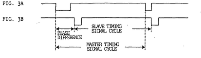
- FIGS. 3A and 3B are explanatory diagrams of this cycle difference and phase difference.
- FIG. 3A shows the timing signal from the master unit 1
- FIG. 3B shows the timing signal output from the cycle signal generator 21 of the slave units 21, 22 ...., 2n.
- the phase comparator 23 determines the phase difference based on the difference between the trailing edge of the timing signal from the master unit 1 (FIG. 3A) and the trailing edge of the timing signal from the cycle signal generator 21 (FIG. 3B).
- the cycle difference finder 22 determines the cycle difference based on the difference between the timing signal cycle (length of time between the trailing edges of the timing signal) from the master unit 1 (length of rising edge) and the default timing signal cycle set in the cycle setting register 27 of the slave unit.
- the cycle difference output from the cycle difference finder 22 and the phase difference output from the phase comparator 23 are passed through digital filters 24, 25 respectively and then added together by the adder 26 to determine a cycle adjustment amount.
- the cycle signal generator 21 adds the determined cycle adjustment amount to the default cycle to adjust the cycle, thereby generating a timing signal.
- phase comparator 23 is identical to the configuration for determining the phase difference between the timing signal from the master unit and the timing signal from the slave units themselves as described in Japanese Patent Application Laid-Open No. 2006-244264 mentioned above, the phase difference between the two timing signals being determined in consideration of the delay time and so on in the communication path 4 from the master unit 1 to the slave units 21, 22 ...., 2n.
- the cycle difference finder 22 determines the cycle time by counting the clock signal number between trailing edges of the timing signal of the master unit 1 and further determines the difference between this determined cycle time and the default cycle as cycle difference. If the timing signal cycle of the master unit 1 is longer than the default timing signal cycle, then a positive cycle difference is output, but if it is shorter than the default timing signal cycle, on the other hand, a minus cycle difference is output.
- the cycle difference output from the cycle difference finder 22 is passed through the digital filter 24 and the phase difference output from the phase comparator 23 is passed through the digital filter 25 with the object of suppressing noise.
- Normal data communication is also implemented using the communication path 4, and timing signals cannot be transmitted or received without delay regardless of the state of the communication path 4, and any special protocol which allows a signal to be transmitted and received without delay does not have to be used.
- the digital filters 24, 25 are provided to prevent generation of variations in the arrival time of the timing signal from the master unit 1, which is to be received by the slave units 21, 22 ...., 2n, to alleviate the effect of such disturbance on the cycle difference or phase difference, and to suppress this noise. Moreover, the characteristics of the digital filters 24, 25 are made variable so that the communication path 4 or system configuration can be adapted to these digital filters 24, 25.
- the cycle difference and the phase difference are added by the adder 26 to determine the cycle adjustment amount, and the cycle signal generator 21 uses this determined adjustment amount to adjust the timing signal generation cycle.
- the phase difference between the timing signal of the master unit 1 and the timing signal of the slave units 21, 22 ...., 2n is corrected using the phase difference determined by the phase comparator 23. Furthermore, the cycle difference determined by the cycle difference finder 22 is added to this phase difference. The sum value thereof is used as the cycle adjustment amount for adjusting the generation cycle of timing signal generated by the cycle signal generator 21 of the slave units 21, 22 ...., 2n.
- phase difference and cycle difference between the timing signal of the master unit 1 and the timing signal of the slave units 21, 22 ...., 2n themselves are adjusted to be reduced to "0", and the motors M of the master unit 1 and the slave units 21, 22 ...., 2n are synchronized and driven and controlled with high precision.
Landscapes
- Physics & Mathematics (AREA)
- General Physics & Mathematics (AREA)
- Engineering & Computer Science (AREA)
- Automation & Control Theory (AREA)
- Numerical Control (AREA)
- Control Of Multiple Motors (AREA)
- Synchronisation In Digital Transmission Systems (AREA)
- Safety Devices In Control Systems (AREA)
- Hardware Redundancy (AREA)
- Communication Control (AREA)
Abstract
Description
- The present invention relates to a synchronizing control system for a plurality of controllers.
- In a controller such as a numerical controller or a robot controller, the motor control is implemented in accordance with timing signals of a fixed cycle generated by the hardware of the controller, that is to say, by an interpolation cycle (ITP signal). A main CPU of the controller delivers the motion amount of each ITP signal interval to a DSP (digital signal processor) that controls a servomotor. The DSP distributes the command motion amount to each control cycle (position, speed control cycles) obtained by further subdividing of the ITP signal interval to control the position and speed of the motor.
- On the other hand, a system in which a controller such as a numerical controller or robot controller is connected in plurality and a plurality of controllers are synchronously operated is also known.
- In this system, a timing signal from a controller serving as a master unit is transmitted to controllers of slave units by way of a bus or a network, and motors to be driven and controlled by the controllers are synchronously operated as a result of the synchronous operation of the plurality of controllers in accordance with this timing signal.
- While timing signal lag occurs in controllers of this type due to transmission delays and so on, a technique for correcting this lag to generate signals of the same timing has been disclosed (
Japanese Patent Application Laid-Open No. 4-125210 - In addition, a moving body communication system in which, in the data transmission between a base station apparatus and a base station controller, the predicted arrival time of a data frame sent from the base station controller is estimated by the base station apparatus and this predicted arrival time is notified to the base station controller and, at the base station controller, the transmission timing of the data frame is sped up in accordance with this notified predicted arrival time has also been disclosed (see
Japanese Patent Application Laid-Open No. 2001-358793 - As a synchronization system for a plurality of controllers such as numerical controllers or robot controllers connected by a bus or network, a patent application proposing a method for correcting timing signal synchronization lag in which the controller serving as a slave unit itself comprises timing signal generation means, and the master unit and slave unit are synchronized as a result of correction of the phase difference between a timing signal sent from the controller of the master unit and a timing signal generated by the slave unit itself has also been submitted in Japan (
Japanese Patent Application Serial No. 2005-60863 Japanese Patent Application Laid-Open No. 2006-244264 on September 14, 2006 - In the invention described in
Japanese Patent Application Laid-Open No. 2006-244264 - However, in the invention described in
Japanese Patent Application Laid-Open No. 2006-244264 - The present invention relates to a control system in which one controller serving as a master unit and at least one controller serving as a slave unit are connected by a communication path and motors controlled by these controllers are synchronously controlled. The master unit and the slave unit each comprise cycle signal generators for generating timing signals. The slave unit comprises correction amount generation means for receiving the timing signal generated by the cycle signal generator of the master unit, determining a phase difference and a cycle difference between the received timing signal and the timing signal generated by the cycle signal generator of the slave unit, and determining, based on the determined phase difference and cycle difference, a correction amount that allows the timing signal on the slave unit side to follow the timing signal on the master unit side. Thereupon, the cycle signal generator of the slave unit corrects a generation cycle of timing signal, based on the correction amount determined by the correction amount generation means, and outputs the corrected generation cycle of timing signal.
- The controller may be a numerical controller or a robot controller.
- Correction amount detection means may comprises: a phase comparator for measuring the phase difference between a timing signal sent from the master unit and received by the slave unit and a timing signal generated by the slave unit; and a cycle difference finder for measuring the cycle difference between a timing signal sent from the master unit and received by the slave unit and a timing signal generated by the slave unit, thereby generating a correction amount based on the output of the cycle difference finder and the output of the phase comparator.
- Filtering means may be provided to the correction amount generation means, and the correction amount may be determined from the output of the phase comparator which has been processed by the filtering means and the output of the cycle difference finder which has been processed by the filtering means. Characteristics of the filtering means may be variable.
- The present invention provides a control system in which the phase difference and cycle difference between timing signals generated by controllers are corrected. In this control system, the phase and cycle between the timing signal of the master unit and the timing signals of the slave units agree with each other and, accordingly, the motors controlled by the master unit and the slave units can be synchronously controlled with high precision.
- The objects and characterizing features described and implied by the present invention will become apparent in the explanation of the following embodiments given hereinafter with reference to the attached drawings. Of these drawings:
- FIG. 1 is a schematic diagram of one embodiment of a control system according to the present invention;
- FIG. 2 is a block diagram focusing on the configuration of timing signal generation units of the master unit and slave unit from which the control system shown in FIG. 1 is configured; and
- FIGS. 3A and 3B are diagrams for explaining the cycle difference and phase difference between the timing signal from the master unit and the timing signal from the slave unit itself.
- FIG. 1 is a schematic diagram of one embodiment of a control system according to the present invention. A plurality of controllers including a robot controller and a controller for controlling a machine tool are connected to one another through a
communication path 4 such as a serial bus or Ethernet (registered trademark). In carrying out synchronous control, one of these controllers acts as amaster unit 1, while remaining controllers act asslave units - A plurality of
motor drive devices 3 are connected to themaster unit 1 and, furthermore, a plurality of motors M is connected to each of themotor drive devices 3. Thereupon, themaster unit 1 drives and controls the motors M to which it is connected by way of themotor drive devices 3. - A plurality of
motor drive devices 3 are also similarly connected to theslave units motor drive devices 3. Thereupon, theslave units motor drive devices 3. - Numerical controllers and a robot controller, which constitute a
master unit 1 andslave units master unit 1 comprises a timing signal generation unit 1a and each of theslave units - FIG. 2 is a block diagram of the configuration of the timing signal generation units 1a and 2a related to the synchronous control of the
master unit 1 andslave units - The timing signal generation unit 1a of the
master unit 1 comprises anoscillator 10 for generating a clock signal and a cycle signal generator 11 for generating timing signal of a predetermined cycle in accordance with the clock signal from theoscillator 10. Similarly to that of conventional numerical controllers or robot controllers, themaster unit 1 performs an interpolated distribution of a command motion amount to the respective motors M in accordance with the timing signal generated from the cycle signal generator 11 and, as a result, the motors M are driven and controlled by way of themotor drive devices 3. - Furthermore, the timing signal from the cycle signal generator 11 of the
master unit 1 is output to thecommunication path 4 by way of a transceiver 12. - On the other hand, the timing signal generation unit 2a provided in the
slave units oscillator 20 for generating a clock signal and acycle signal generator 21 for generating a timing signal of a predetermined cycle in accordance with this clock signal. The timing signal generation unit 2a further comprises correction amount generation means for determining the correction amount for correcting the generated cycle of the timing signal. Correction amount generation means is configured from acycle difference finder 22,phase comparator 23,digital filters adder 26 andcycle setting register 27. Furthermore, the timing signal generation unit 2a is connected to atransceiver 28 connected to thecommunication path 4. - The
cycle signal generator 21 generates a timing signal of a predetermined cycle in accordance with the clock signal generated from theoscillator 20. The control actuation of theslave units motor drive devices 3 connected to theslave units - In addition, the timing signal generated by the
cycle signal generator 21 is input into thephase comparator 23. The timing signal cycle is set in thecycle setting register 27, and the default timing signal cycle set in thecycle setting register 27 is input into thecycle signal generator 21 andcycle difference finder 22. Furthermore, the timing signal from themaster unit 1 received by thetransceiver 28 is also input into thecycle difference finder 22 andphase comparator 23. Thereupon, the cycle difference finder 22 determines the difference (cycle time difference) between the timing signal cycle from themaster unit 1 and the default timing signal cycle set in thecycle setting register 27, and outputs the determined difference. - In addition, the
phase comparator 23 determines the phase difference between the timing signal from themaster unit 1 and the timing signal output from thecycle signal generator 21 of theslave units - FIGS. 3A and 3B are explanatory diagrams of this cycle difference and phase difference. FIG. 3A shows the timing signal from the
master unit 1, and FIG. 3B shows the timing signal output from thecycle signal generator 21 of theslave units phase comparator 23 determines the phase difference based on the difference between the trailing edge of the timing signal from the master unit 1 (FIG. 3A) and the trailing edge of the timing signal from the cycle signal generator 21 (FIG. 3B). Thecycle difference finder 22 determines the cycle difference based on the difference between the timing signal cycle (length of time between the trailing edges of the timing signal) from the master unit 1 (length of rising edge) and the default timing signal cycle set in thecycle setting register 27 of the slave unit. - The cycle difference output from the
cycle difference finder 22 and the phase difference output from thephase comparator 23 are passed throughdigital filters adder 26 to determine a cycle adjustment amount. Thecycle signal generator 21 adds the determined cycle adjustment amount to the default cycle to adjust the cycle, thereby generating a timing signal. - The configuration of the
phase comparator 23 is identical to the configuration for determining the phase difference between the timing signal from the master unit and the timing signal from the slave units themselves as described inJapanese Patent Application Laid-Open No. 2006-244264 communication path 4 from themaster unit 1 to theslave units - In addition, the
cycle difference finder 22 determines the cycle time by counting the clock signal number between trailing edges of the timing signal of themaster unit 1 and further determines the difference between this determined cycle time and the default cycle as cycle difference. If the timing signal cycle of themaster unit 1 is longer than the default timing signal cycle, then a positive cycle difference is output, but if it is shorter than the default timing signal cycle, on the other hand, a minus cycle difference is output. - The cycle difference output from the
cycle difference finder 22 is passed through thedigital filter 24 and the phase difference output from thephase comparator 23 is passed through thedigital filter 25 with the object of suppressing noise. Normal data communication is also implemented using thecommunication path 4, and timing signals cannot be transmitted or received without delay regardless of the state of thecommunication path 4, and any special protocol which allows a signal to be transmitted and received without delay does not have to be used. - The
digital filters master unit 1, which is to be received by theslave units digital filters communication path 4 or system configuration can be adapted to thesedigital filters - The cycle difference and the phase difference are added by the
adder 26 to determine the cycle adjustment amount, and thecycle signal generator 21 uses this determined adjustment amount to adjust the timing signal generation cycle. - Similarly to the invention described in
Japanese Patent Application Laid-Open No. 2006-244264 master unit 1 and the timing signal of theslave units phase comparator 23. Furthermore, the cycle difference determined by thecycle difference finder 22 is added to this phase difference. The sum value thereof is used as the cycle adjustment amount for adjusting the generation cycle of timing signal generated by thecycle signal generator 21 of theslave units master unit 1 and the timing signal of theslave units master unit 1 and theslave units
Claims (5)
- A control system in which one controller serving as a master unit and at least one controller serving as a slave unit are connected by a communication path and motors controlled by these controllers are synchronously controlled, wherein
the master unit and the slave unit each comprise cycle signal generators for generating timing signals,
the slave unit comprises correction amount generation means for receiving the timing signal generated by the cycle signal generator of the master unit, determining a phase difference and a cycle difference between the received timing signal and the timing signal generated by the cycle signal generator of the slave unit, and determining, based on the determined phase difference and cycle difference, a correction amount that allows the timing signal on the slave unit side to follow the timing signal on the master unit side, and
the cycle signal generator of the slave unit corrects a generation cycle of timing signal, based on the correction amount determined by the correction amount generation means, and outputs the corrected generation cycle of timing signal. - The control system according to claim 1, wherein said controller is a numerical controller or a robot controller.
- The control system according to claim 1 or 2, wherein
said correction amount detection means comprises:a phase comparator for measuring the phase difference between a timing signal sent from the master unit and received by the slave unit and a timing signal generated by the slave unit; anda cycle difference finder for measuring the cycle difference between a timing signal sent from the master unit and received by the slave unit and a timing signal generated by the slave unit,thereby generating a correction amount based on the output of the cycle difference finder and the output of the phase comparator. - The control system according to claim 3, wherein
filtering means is provided to the correction amount generation means, and
the correction amount is determined from the output of the phase comparator which has been processed by the filtering means and the output of the cycle difference finder which has been processed by the filtering means. - The control system according to claim 4, wherein characteristics of the filtering means are variable.
Applications Claiming Priority (1)
| Application Number | Priority Date | Filing Date | Title |
|---|---|---|---|
| JP2006036847A JP2007219642A (en) | 2006-02-14 | 2006-02-14 | Control system |
Publications (3)
| Publication Number | Publication Date |
|---|---|
| EP1818742A2 true EP1818742A2 (en) | 2007-08-15 |
| EP1818742A3 EP1818742A3 (en) | 2009-11-04 |
| EP1818742B1 EP1818742B1 (en) | 2012-10-10 |
Family
ID=37866278
Family Applications (1)
| Application Number | Title | Priority Date | Filing Date |
|---|---|---|---|
| EP07250349A Ceased EP1818742B1 (en) | 2006-02-14 | 2007-01-29 | Synchronizing control system for a plurality of controllers |
Country Status (4)
| Country | Link |
|---|---|
| US (1) | US7525263B2 (en) |
| EP (1) | EP1818742B1 (en) |
| JP (1) | JP2007219642A (en) |
| CN (1) | CN101021727A (en) |
Cited By (2)
| Publication number | Priority date | Publication date | Assignee | Title |
|---|---|---|---|---|
| WO2010088009A1 (en) * | 2009-01-28 | 2010-08-05 | Ge Intelligent Platforms, Inc. | System and method for path planning |
| EP2278699A1 (en) * | 2008-02-29 | 2011-01-26 | Husqvarna AB | Electric saw communication |
Families Citing this family (17)
| Publication number | Priority date | Publication date | Assignee | Title |
|---|---|---|---|---|
| KR101044521B1 (en) | 2008-12-31 | 2011-06-27 | 엘에스산전 주식회사 | Synchronous control device of slave devices connected to network |
| CN101860123B (en) * | 2009-04-13 | 2012-03-21 | 中山大洋电机股份有限公司 | Electric machine |
| JP5850045B2 (en) * | 2011-03-30 | 2016-02-03 | 吉成 河 | Expansion module and base board / expansion module connection structure |
| JP2015229462A (en) * | 2014-06-06 | 2015-12-21 | 富士電機株式会社 | Synchronization system |
| JP6247247B2 (en) * | 2015-04-10 | 2017-12-13 | ファナック株式会社 | Control system |
| JP6200456B2 (en) * | 2015-06-29 | 2017-09-20 | ファナック株式会社 | Interference check system between machine tool and robot |
| ITUB20153295A1 (en) | 2015-08-31 | 2017-03-03 | Marposs Spa | SYSTEM AND METHOD OF DATA PROCESSING AND TRANSMISSION |
| JP6400553B2 (en) * | 2015-09-28 | 2018-10-03 | ファナック株式会社 | Numerical control system with synchronous control function between units |
| KR102543212B1 (en) * | 2015-10-26 | 2023-06-14 | (주)한화 | System and method for controlling robot |
| JP6380432B2 (en) | 2016-03-14 | 2018-08-29 | オムロン株式会社 | Motor control system, motor control device, program, and recording medium |
| DE102016226256A1 (en) * | 2016-12-28 | 2018-06-28 | Robert Bosch Gmbh | Electric machine with synchronous pulse pattern generation |
| CN106862978B (en) * | 2017-02-15 | 2020-09-15 | 深圳市标特福精密机械电子有限公司 | Distributed linear motor processing platform and distributed linear motor control method |
| JP2020106937A (en) * | 2018-12-26 | 2020-07-09 | ファナック株式会社 | Numerical control device |
| CN113381652A (en) * | 2021-06-30 | 2021-09-10 | 深圳市杰美康机电有限公司 | Stepping drive serial port interconnection system and method |
| JP7617050B2 (en) * | 2022-01-25 | 2025-01-17 | 株式会社日立製作所 | Device control device, control system, and control method |
| EP4311135B1 (en) * | 2022-07-19 | 2025-04-09 | ABB Schweiz AG | Time synchronization between a master and a slave in a network |
| JP2024015630A (en) * | 2022-07-25 | 2024-02-06 | オムロン株式会社 | Control system, communication device and control method |
Citations (7)
| Publication number | Priority date | Publication date | Assignee | Title |
|---|---|---|---|---|
| JPH04135210A (en) | 1990-09-27 | 1992-05-08 | Fanuc Ltd | Synchronizing signal generator |
| US5511100A (en) | 1993-12-13 | 1996-04-23 | Motorola, Inc. | Method and apparatus for performing frequency detection |
| US6118836A (en) | 1997-12-18 | 2000-09-12 | Alcatel Usa Sourcing L.P. | Frequency and phase locking apparatus |
| JP2001358793A (en) | 2000-06-12 | 2001-12-26 | Matsushita Electric Ind Co Ltd | Inter-node synchronization device and inter-node synchronization method |
| EP1274190A2 (en) | 2001-07-02 | 2003-01-08 | Motorola, Inc. | Time synchronisation system and method |
| US6603830B1 (en) | 1999-02-15 | 2003-08-05 | Siemens Aktiengesellschaft | Synchronization method for a receiving unit and a receiving unit corresponding thereto |
| US20060001464A1 (en) | 2003-03-06 | 2006-01-05 | Fujitsu Limited | Digital PLL circuit |
Family Cites Families (13)
| Publication number | Priority date | Publication date | Assignee | Title |
|---|---|---|---|---|
| DE1032117B (en) * | 1955-02-22 | 1958-06-12 | Halleiner Motorenwerke Hinterb | Cooling device for scooters or the like. |
| JPH084393B2 (en) * | 1989-06-01 | 1996-01-17 | 株式会社日立製作所 | Rotary storage |
| US5104837A (en) * | 1990-03-16 | 1992-04-14 | Phillips Petroleum Company | Catalyst and polymerization of olefins |
| DE4216824A1 (en) * | 1991-06-04 | 1992-12-10 | Hauni Werke Koerber & Co Kg | METHOD AND DEVICE FOR CONTROLLING A PACKING MACHINE |
| JPH08123520A (en) * | 1994-10-25 | 1996-05-17 | Mitsubishi Electric Corp | Drive control command device, synchronous control system of a plurality of drive control command devices, and synchronous control method thereof |
| DE19626287A1 (en) * | 1996-07-01 | 1997-02-13 | Abb Management Ag | Method for operating a drive system and device for carrying out the method |
| TW454110B (en) | 1998-12-17 | 2001-09-11 | Matsushita Electric Industrial Co Ltd | Frequency control and phase synchronization circuit |
| DE60119212T2 (en) * | 2000-04-24 | 2007-02-15 | Aida Engineering, Ltd., Sagamihara | Method for controlling the synchronous drive of a press and press for the application of this method |
| DE10059270B4 (en) * | 2000-11-29 | 2012-08-02 | Heidelberger Druckmaschinen Ag | Apparatus and method for synchronizing processes running on multiple units |
| DE10312379B4 (en) * | 2002-04-04 | 2018-06-28 | Heidelberger Druckmaschinen Ag | Method and device for the synchronization of drive combinations |
| JP2005014150A (en) | 2003-06-26 | 2005-01-20 | Yaskawa Electric Corp | Robot system |
| JP4261500B2 (en) * | 2005-03-04 | 2009-04-30 | ファナック株式会社 | Control system |
| JP4185926B2 (en) | 2005-08-26 | 2008-11-26 | ファナック株式会社 | Robot cooperative control method and system |
-
2006
- 2006-02-14 JP JP2006036847A patent/JP2007219642A/en active Pending
-
2007
- 2007-01-29 EP EP07250349A patent/EP1818742B1/en not_active Ceased
- 2007-02-07 US US11/703,239 patent/US7525263B2/en not_active Expired - Fee Related
- 2007-02-13 CN CNA2007100055945A patent/CN101021727A/en active Pending
Patent Citations (7)
| Publication number | Priority date | Publication date | Assignee | Title |
|---|---|---|---|---|
| JPH04135210A (en) | 1990-09-27 | 1992-05-08 | Fanuc Ltd | Synchronizing signal generator |
| US5511100A (en) | 1993-12-13 | 1996-04-23 | Motorola, Inc. | Method and apparatus for performing frequency detection |
| US6118836A (en) | 1997-12-18 | 2000-09-12 | Alcatel Usa Sourcing L.P. | Frequency and phase locking apparatus |
| US6603830B1 (en) | 1999-02-15 | 2003-08-05 | Siemens Aktiengesellschaft | Synchronization method for a receiving unit and a receiving unit corresponding thereto |
| JP2001358793A (en) | 2000-06-12 | 2001-12-26 | Matsushita Electric Ind Co Ltd | Inter-node synchronization device and inter-node synchronization method |
| EP1274190A2 (en) | 2001-07-02 | 2003-01-08 | Motorola, Inc. | Time synchronisation system and method |
| US20060001464A1 (en) | 2003-03-06 | 2006-01-05 | Fujitsu Limited | Digital PLL circuit |
Cited By (5)
| Publication number | Priority date | Publication date | Assignee | Title |
|---|---|---|---|---|
| EP2278699A1 (en) * | 2008-02-29 | 2011-01-26 | Husqvarna AB | Electric saw communication |
| US9327424B2 (en) | 2008-02-29 | 2016-05-03 | Husqvarna Ab | Electric saw communication |
| WO2010088009A1 (en) * | 2009-01-28 | 2010-08-05 | Ge Intelligent Platforms, Inc. | System and method for path planning |
| CN102301291A (en) * | 2009-01-28 | 2011-12-28 | 通用电气智能平台有限公司 | System and method for path planning |
| CN102301291B (en) * | 2009-01-28 | 2014-04-16 | 通用电气智能平台有限公司 | System and method for path planning |
Also Published As
| Publication number | Publication date |
|---|---|
| JP2007219642A (en) | 2007-08-30 |
| US20070188116A1 (en) | 2007-08-16 |
| EP1818742A3 (en) | 2009-11-04 |
| EP1818742B1 (en) | 2012-10-10 |
| US7525263B2 (en) | 2009-04-28 |
| CN101021727A (en) | 2007-08-22 |
Similar Documents
| Publication | Publication Date | Title |
|---|---|---|
| US7525263B2 (en) | Control system | |
| EP1757410B1 (en) | Robot coordinated control method and system | |
| EP3065012B1 (en) | Control device and method of synchronizing control | |
| JP3923047B2 (en) | Synchronous control device | |
| JP5314110B2 (en) | Motor controller for synchronous control of master axis and slave axis | |
| JP3945403B2 (en) | Servo motor drive control system | |
| EP1912325B1 (en) | Electronic line shaft with phased lock loop filtering and predicting | |
| KR20150103561A (en) | EtherCAT CONTROL DEVICE AND FACTORY AUTOMATION SYSTEM HAVING THE SAME | |
| WO2017195578A1 (en) | Motor control system | |
| JP3386777B2 (en) | Numerical control system | |
| WO2019107022A1 (en) | Control device and control method | |
| JP4261500B2 (en) | Control system | |
| JP5905545B2 (en) | I/O Control System | |
| CN111208784B (en) | Motion control system and synchronization method thereof | |
| JP2013062928A (en) | Synchronous control system | |
| JP4487522B2 (en) | Motor drive device | |
| CN118233569B (en) | Grating signal processing method, equipment and storage medium based on FPGA | |
| JP2007025759A (en) | Electric motor drive device, position command device, and positioning device | |
| WO2003100536A1 (en) | Numerical value control device synchronization control method | |
| JP4638094B2 (en) | Multi-axis control device and synchronization method therefor | |
| JP7127594B2 (en) | Control device | |
| JP2017068353A (en) | Numerical control system having synchronous control function between unit | |
| KR100493606B1 (en) | Servo motor drive control system | |
| EP4571437A1 (en) | Field bus system | |
| WO2019123998A1 (en) | Synchronous control device |
Legal Events
| Date | Code | Title | Description |
|---|---|---|---|
| PUAI | Public reference made under article 153(3) epc to a published international application that has entered the european phase |
Free format text: ORIGINAL CODE: 0009012 |
|
| AK | Designated contracting states |
Kind code of ref document: A2 Designated state(s): AT BE BG CH CY CZ DE DK EE ES FI FR GB GR HU IE IS IT LI LT LU LV MC NL PL PT RO SE SI SK TR |
|
| AX | Request for extension of the european patent |
Extension state: AL BA HR MK YU |
|
| PUAL | Search report despatched |
Free format text: ORIGINAL CODE: 0009013 |
|
| AK | Designated contracting states |
Kind code of ref document: A3 Designated state(s): AT BE BG CH CY CZ DE DK EE ES FI FR GB GR HU IE IS IT LI LT LU LV MC NL PL PT RO SE SI SK TR |
|
| AX | Request for extension of the european patent |
Extension state: AL BA HR MK RS |
|
| 17P | Request for examination filed |
Effective date: 20100329 |
|
| 17Q | First examination report despatched |
Effective date: 20100429 |
|
| AKX | Designation fees paid |
Designated state(s): DE |
|
| RAP1 | Party data changed (applicant data changed or rights of an application transferred) |
Owner name: FANUC CORPORATION |
|
| GRAP | Despatch of communication of intention to grant a patent |
Free format text: ORIGINAL CODE: EPIDOSNIGR1 |
|
| GRAS | Grant fee paid |
Free format text: ORIGINAL CODE: EPIDOSNIGR3 |
|
| GRAA | (expected) grant |
Free format text: ORIGINAL CODE: 0009210 |
|
| AK | Designated contracting states |
Kind code of ref document: B1 Designated state(s): DE |
|
| REG | Reference to a national code |
Ref country code: DE Ref legal event code: R096 Ref document number: 602007025979 Country of ref document: DE Effective date: 20121213 |
|
| PLBE | No opposition filed within time limit |
Free format text: ORIGINAL CODE: 0009261 |
|
| STAA | Information on the status of an ep patent application or granted ep patent |
Free format text: STATUS: NO OPPOSITION FILED WITHIN TIME LIMIT |
|
| 26N | No opposition filed |
Effective date: 20130711 |
|
| REG | Reference to a national code |
Ref country code: DE Ref legal event code: R097 Ref document number: 602007025979 Country of ref document: DE Effective date: 20130711 |
|
| REG | Reference to a national code |
Ref country code: DE Ref legal event code: R082 Ref document number: 602007025979 Country of ref document: DE Representative=s name: HL KEMPNER PATENTANWALT, RECHTSANWALT, SOLICIT, DE |
|
| PGFP | Annual fee paid to national office [announced via postgrant information from national office to epo] |
Ref country code: DE Payment date: 20210119 Year of fee payment: 15 |
|
| REG | Reference to a national code |
Ref country code: DE Ref legal event code: R119 Ref document number: 602007025979 Country of ref document: DE |
|
| PG25 | Lapsed in a contracting state [announced via postgrant information from national office to epo] |
Ref country code: DE Free format text: LAPSE BECAUSE OF NON-PAYMENT OF DUE FEES Effective date: 20220802 |