EP1818653A2 - Magnetostriktiver Positionssensor - Google Patents
Magnetostriktiver Positionssensor Download PDFInfo
- Publication number
- EP1818653A2 EP1818653A2 EP07000961A EP07000961A EP1818653A2 EP 1818653 A2 EP1818653 A2 EP 1818653A2 EP 07000961 A EP07000961 A EP 07000961A EP 07000961 A EP07000961 A EP 07000961A EP 1818653 A2 EP1818653 A2 EP 1818653A2
- Authority
- EP
- European Patent Office
- Prior art keywords
- magnetostrictive
- sensor according
- elements
- sensor
- magnetic element
- Prior art date
- Legal status (The legal status is an assumption and is not a legal conclusion. Google has not performed a legal analysis and makes no representation as to the accuracy of the status listed.)
- Granted
Links
- 230000005291 magnetic effect Effects 0.000 claims abstract description 52
- 239000013013 elastic material Substances 0.000 claims description 7
- 238000003780 insertion Methods 0.000 claims description 6
- 238000006073 displacement reaction Methods 0.000 claims description 2
- 239000007788 liquid Substances 0.000 claims description 2
- 238000000034 method Methods 0.000 claims description 2
- 238000001514 detection method Methods 0.000 claims 1
- 230000000694 effects Effects 0.000 description 6
- 238000010586 diagram Methods 0.000 description 5
- 238000005259 measurement Methods 0.000 description 4
- 238000005452 bending Methods 0.000 description 2
- 230000007613 environmental effect Effects 0.000 description 2
- 239000003302 ferromagnetic material Substances 0.000 description 2
- 239000000463 material Substances 0.000 description 2
- 230000001960 triggered effect Effects 0.000 description 2
- 230000003750 conditioning effect Effects 0.000 description 1
- 230000001419 dependent effect Effects 0.000 description 1
- 238000013461 design Methods 0.000 description 1
- 238000011161 development Methods 0.000 description 1
- 230000018109 developmental process Effects 0.000 description 1
- 238000003745 diagnosis Methods 0.000 description 1
- 239000000428 dust Substances 0.000 description 1
- 230000004907 flux Effects 0.000 description 1
- 238000009434 installation Methods 0.000 description 1
- 230000001681 protective effect Effects 0.000 description 1
- 238000012552 review Methods 0.000 description 1
- 239000000523 sample Substances 0.000 description 1
- 238000012360 testing method Methods 0.000 description 1
- 238000012546 transfer Methods 0.000 description 1
Images





Classifications
-
- G—PHYSICS
- G01—MEASURING; TESTING
- G01D—MEASURING NOT SPECIALLY ADAPTED FOR A SPECIFIC VARIABLE; ARRANGEMENTS FOR MEASURING TWO OR MORE VARIABLES NOT COVERED IN A SINGLE OTHER SUBCLASS; TARIFF METERING APPARATUS; MEASURING OR TESTING NOT OTHERWISE PROVIDED FOR
- G01D5/00—Mechanical means for transferring the output of a sensing member; Means for converting the output of a sensing member to another variable where the form or nature of the sensing member does not constrain the means for converting; Transducers not specially adapted for a specific variable
- G01D5/48—Mechanical means for transferring the output of a sensing member; Means for converting the output of a sensing member to another variable where the form or nature of the sensing member does not constrain the means for converting; Transducers not specially adapted for a specific variable using wave or particle radiation means
- G01D5/485—Mechanical means for transferring the output of a sensing member; Means for converting the output of a sensing member to another variable where the form or nature of the sensing member does not constrain the means for converting; Transducers not specially adapted for a specific variable using wave or particle radiation means using magnetostrictive devices
-
- F—MECHANICAL ENGINEERING; LIGHTING; HEATING; WEAPONS; BLASTING
- F41—WEAPONS
- F41G—WEAPON SIGHTS; AIMING
- F41G3/00—Aiming or laying means
- F41G3/22—Aiming or laying means for vehicle-borne armament, e.g. on aircraft
Definitions
- the invention relates to a magnetostrictive position sensor with the features of the preamble of patent claim 1, the use of this sensor according to claim 12 and a method for determining the position with the features of the preamble of claim 16.
- the invention is based on the magnetostrictive effect.
- Magnetostrictive sensors have been known for a long time.
- the DE 20 2004 002 891 U1 describes, for example, a magnetostrictive path sensor which has a wire or tubular waveguide made of a magnetostrictive material extending in the measuring direction.
- a mechanical-elastic wave for example, due to the Wiedemann effect, which propagates in both directions along the waveguide and can be detected at the ends. Due to the measured transit time of the mechanical-elastic shaft, the exact distance of the position magnet from the end of the waveguide can be determined and thus the position of a movable assembly to which the position magnet is attached.
- the waveguide is received in a support body, eg a tube, in order to achieve a mechanically stable support and to enable an arrangement on a corresponding component.
- the electronic components are arranged at one end of the waveguide, such as a detector coil, a Villary ribbon or a piezoelectric transducer, a signal conditioning and a diagnostic output. These elements are housed in a housing and thus protected against environmental influences.
- the known sensor consists essentially of two elements, the magnetostrictive element and the magnetic element, which are moved relative to one another. Such a configuration is unsuitable for a stationary tactile sensor, which is to detect a position which is predetermined by external pressure on the sensor.
- Magnetostrictive displacement sensors with individual movable position magnets are further described in the DE 102 01 880 A1 , of the DE 197 0081 A1 and the US 3,898,555 ,
- the invention can be used in a rapid-insertion device in a vehicle, in particular in a combat vehicle.
- Fast entry devices are known per se.
- a quick-insertion device is used, for example, when in a combat vehicle or observation vehicle the environment is visually observed from within the vehicle.
- the observation can be done either directly or from an open hatch or fixed angle mirrors.
- the observer Once the observer discovers a potential target, it must be detected by a rotatably mounted periscope whose field of view is severely limited for more accurate assessment. It is necessary to direct the periscope (and possibly a gun barrel) as quickly as possible in the direction of the target, ie the observer must transfer the direction which he has visually detected to the periscope so that, when subsequently viewed through it, he can move rapidly in the direction of the target Environment finds its way around.
- the EP 0 455 838 B1 describes such a quick-reference device for a servo-driven straightening on an observation or gun vehicle, serving as an angle encoder, annularly around the observation place mounted on the vehicle Tastpotentiometer, wherein the Tastpotentiometer includes a flexible resistance path and a flexible contact path in a hose-like insulating in radial Distance are guided longitudinally displaceable, whereby the Tastpotentiometer various bending radii is adaptable, and wherein it is attached to a lining profile of the observer's place and is determined by this in its ring shape.
- the vehicle described also has an observation hatch, wherein the Tastpotentiometer is integrated into the lining profile of the hatch edge of the observation hatch.
- a disadvantage of this embodiment is that a regular calibration, adjustment and resistance testing is necessary u.a. by a temperature dependence of the resistance material. Furthermore, the measurement is not contactless, so that due to signs of wear, the life is limited.
- the object of the invention is to design a stationary sensor such that with high accuracy and low temperature dependence by a by outside of the sensor element exerted mechanical pressure predetermined position can be determined.
- the position sensor according to the invention should, in particular, be able to be used as a quick-insertion device.
- the invention solves the task device with the features of the characterizing part of patent claim 1 and procedurally with the features of the characterizing part of claim 16.
- the use of the invention as a tactile sensor is part of claim 12.
- the position sensor which has a magnetic element, a magnetostrictive element, a detector and a pulse generator, wherein the magnetic element to the magnetostrictive element has a predetermined distance, characterized in that the magnetic element and / or the magnetostrictive element are designed so flexible in that when mechanical pressure is applied to a location on one of the elements, the distance between the elements at that location is reduced, and that the sensor comprises a reset device which, after a pressure has been exerted on one of the elements, the predetermined distance between the elements restores.
- the predetermined distance is dimensioned such that no magnetostrictive effect occurs in this unactuated state, ie the distance of the two elements is above a predetermined threshold value.
- the pulse generator generates at predetermined time intervals current pulses, which are passed through the magnetostrictive wire. Once the distance between the magnetic element and the magnetostrictive element is reduced, the magnetostrictive effect may occur as a result of exceeding a minimum magnetic flux density. The distance between the two elements is now below the predetermined threshold. It is thus triggered as a signal, a mechanical-elastic wave, which is received by the detector. Over the duration of the signal, the position of the pressure point be determined.
- the magnetic element extends parallel to the magnetostrictive element.
- the magnetic element has individual, juxtaposed permanent magnets. It can also be designed strip-shaped. The band can be occupied with sufficiently narrow permanent magnets in a correspondingly large number, wherein the permanent magnets can be embedded in plastic.
- a magnetostrictive element a magnetostrictive wire is preferably used.
- a layer of an elastic material can be arranged between the magnetic and the magnetostrictive element.
- a layer of a foam-like plastic may be located between the elements.
- a further advantageous embodiment provides that in order to achieve the necessary restoring force, the magnetic and the magnetostrictive element are arranged on two opposite sides of a flexible, deformable hollow element which is filled with a gas and / or a liquid.
- the senor has a shield which encloses the magnetostrictive and the magnetic element and which provides a magnetic shield.
- the shield may for example consist of a ferro-magnetic material.
- the shield may also have a U-shaped profile.
- the shielding not only gives good EMC properties, but also a robustness against environmental influences such as moisture and dust pollution.
- the shield can serve as a fastener. Due to the flexible elements used, it is possible to bend the entire sensor.
- the sensor is designed circular. Depending on the type of elements used, bending radii of less than 12 cm can be achieved.
- the sensor can be used as a quick-insertion device in a vehicle, in particular in a combat vehicle or observation vehicle. In this case, it can be arranged around an observation station in the interior of the vehicle or along the circumference of an observation hatch of the vehicle.
- the sensor is used as Azimutwinkelgeber.
- the sensor is used position-independently in the room, so that the installation position of the sensor for its function is irrelevant.
- the temperature dependence of the sensor is negligible in terms of determining the position of the probe, thus eliminating a review and adjustment.
- the magnetic element and the magnetostrictive element do not come into contact during the measurement, thereby increasing the life of the sensor.
- the sensor is also characterized by high accuracy and resolution.
- the sensor can be easily connected directly to common fieldbus systems via an interface. It can also be used fault diagnosis systems that automatically check the condition of the sensor.
- Fig. 1 shows a first embodiment of a position sensor in longitudinal section in the unactuated state.
- the sensor has as a magnetic element a flexible magnetic tape 1 and a magnetostrictive element to a magnetostrictive wire 3, which is embedded in a protective sheath, not shown.
- the wire 3 and the magnetic tape 1 are parallel to each other.
- the sensor further comprises a shield 4 made of a ferro-magnetic material.
- Fig. 2 shows the sensor of Fig. 1 with the magnetic tape 1, the magnetostrictive wire 3, the elastic material 2 and the shield 4 in cross-section along the section line AA 'in Fig. 1.
- the shield 4 has a U-shaped profile on.
- the distance between the wire 3 and the magnetic tape 4 is dimensioned such that in this unactuated state no magnetostrictive effect occurs, i. the distance of the two elements is above a predetermined threshold.
- Fig. 3 shows the sensor of Fig. 1 in longitudinal section in the actuated state.
- the sensor can be operated, for example, in a manner not shown by a finger.
- the magnetic tape 1 and the elastic material 2 deforms, so that the distance between the magnetostrictive wire 3 and the magnetic tape 1 is reduced and is below the predetermined threshold value.
- Current pulses generated by the wire generated by a unit 7 shown in FIG. 7 generate a circular magnetic field which propagates in the measuring direction. If this magnetic field is penetrated by the perpendicular magnetic field of the approximated magnetic tape 1, the magnetostrictive effect sets in and an ultrasonic signal is generated, by means of which the position x 0 of the pressure point can be determined.
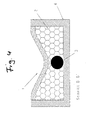
- FIG. 4 shows the sensor of FIG. 3 in cross-section according to the section line BB 'in FIG. 3. It will be clear that the magnetostrictive wire 3 and the magnetic tape 1 do not touch, i. the measurement is made contactless in this sense.
- Fig. 5 shows the structure of the flexible magnetic tape 1 in a plan view and in a longitudinal section along the section line CC '.
- the magnetic tape 1 has juxtaposed permanent magnets, which are embedded in a plastic.
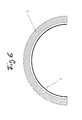
- the touch sensor 6 shows a detail of a schematic diagram of a touch sensor 6.
- the touch sensor 6 is disposed on an edge of an observation hatch 5 of a vehicle, not shown, and is used as a quick-insertion device.
- Fig. 7 shows a block diagram of the sensor.
- a unit 7 which provides the pulse generation and the transit time measurement.
- the magnetomechanical transducer 9 serves as a detector for receiving the mechanical-elastic wave in the waveguide. The determined position values are made available via the interface 8.
- FIG. 8 shows a second embodiment of a sensor in cross-section, which has as a magnetic element a flexible magnetic tape 10, on which permanent magnets are arranged, and as a magnetostrictive element a magnetostrictive wire 9.
- the two elements are embedded on two opposite sides of a hollow element 11, which consists of an elastic material and a magnetic shield leitstet.
- the hollow element 11 is gas filled and causes the required restoring force.
Landscapes
- Engineering & Computer Science (AREA)
- Physics & Mathematics (AREA)
- General Physics & Mathematics (AREA)
- Aviation & Aerospace Engineering (AREA)
- General Engineering & Computer Science (AREA)
- Measurement Of Length, Angles, Or The Like Using Electric Or Magnetic Means (AREA)
- Measuring Fluid Pressure (AREA)
Abstract
Description
- Die Erfindung betrifft einen magnetostriktiven Positionssensor mit den Merkmalen aus dem Oberbegriff des Patentanspruchs 1, die Verwendung dieses Sensors gemäß Patentanspruch 12 sowie ein Verfahren zur Positionsbestimmung mit den Merkmalen aus dem Oberbegriff des Patentanspruchs 16.
- Die Erfindung beruht auf dem magnetostriktiven Effekt. Magnetostriktive Sensoren sind seit langem bekannt. Die
DE 20 2004 002 891 U1 beschreibt beispielsweise einen magnetostriktiven Streckensensor, welcher einen draht- oder rohrförmigen in Messrichtung verlaufenden Wellenleiter aus einem magnetostriktiven Material aufweist. Durch einen kontaktlos nah an den Wellenleiter herangebrachten Positionsmagneten wird mittels Überlagerung von Magnetfeldern eine mechanisch-elastische Welle ausgelöst, beispielsweise auf Grund des Wiedemanneffekts, die sich in beiden Richtungen entlang des Wellenleiters ausbreitet und an dessen Enden detektiert werden kann. Auf Grund der gemessenen Laufzeit der mechanisch-elastischen Welle kann die exakte Entfernung des Positionsmagneten von dem Ende des Wellenleiters bestimmt werden und damit die Position einer beweglichen Baugruppe, an welcher der Positionsmagnet befestigt ist. Der Wellenleiter wird in einem Stützkörper, z.B. einem Rohr aufgenommen, um eine mechanisch stabile Halterung zu erreichen und eine Anordnung an einem entsprechenden Bauteil zu ermöglichen. Die elektronischen Bauteile sind an einem Ende des Wellenleiters angeordnet, so beispielsweise eine Detektorspule, ein Villary-Bändchen oder ein piezoelektrischer Aufnehmer, eine Signalaufbereitung und eine Diagnoseausgabe. Diese Elemente sind in einem Gehäuse untergebracht und damit gegen Umgebungseinflüsse geschützt. - Nachteilig an dieser Ausgestaltung ist, dass der Positionsmagnet bewegt werden muss. Der bekannte Sensor besteht im Wesentlichen aus zwei Elementen, dem magnetostriktiven Element und dem magnetischen Element, welche relativ zueinander bewegt werden. Eine solche Ausgestaltung ist ungeeignet für einen ortsfesten Tastsensor, welcher eine Position, die durch äußeren Druck auf den Sensor vorgegebenen wird, detektieren soll.
- Magnetostriktive Wegsensoren mit einzelnen beweglichen Positionsmagneten werden ferner beschrieben in der
DE 102 01 880 A1 , derDE 197 0081 A1 und derUS 3,898,555 . - Die Erfindung kann Einsatz finden bei einer Schnelleinweisungsvorrichtung in einem Fahrzeug, insbesondere in einem Kampffahrzeug. Schnelleinweisungsvorrichtungen sind an sich bekannt. Eine Schnelleinweisungsvorrichtung wird beispielsweise verwendet, wenn bei einem Kampffahrzeug oder Beobachtungsfahrzeug die Umgebung aus dem Innern des Fahrzeugs visuell beobachtet wird.
- Die Beobachtung kann entweder direkt oder aus einer offenen Luke oder über fest eingebaute Winkelspiegel erfolgen. Sobald der Beobachter ein mögliches Ziel entdeckt, so muss dieses zur genaueren Beurteilung durch ein drehbar montiertes Periskop erfasst werden, dessen Gesichtsfeld stark eingeschränkt ist. Es ist notwendig, das Periskop (und gegebenenfalls ein Geschützrohr) möglichst rasch in die Richtung des Ziels einzuweisen, d.h. der Beobachter muss die Richtung, welche er visuell erfasst hat, auf das Periskop übertragen, damit er bei anschließender Sicht durch dieses sich rasch in der Umgebung zurechtfindet. Die
EP 0 455 838 B1 beschreibt eine solche Schnelleinweisungsvorrichtung für eine servogetriebene Richtvorrichtung an einem Beobachtungs- oder Geschützfahrzeug, mit einem als Winkelgeber dienenden, ringförmig um den Beobachtungsplatz herum am Fahrzeug angebrachten Tastpotentiometer, wobei das Tastpotentiometer eine flexible Widerstandsbahn und eine flexible Kontaktbahn enthält, die in einer schlauchähnlichen Isolierhülle in radialem Abstand voneinander längsverschieblich geführt sind, wodurch das Tastpotentiometer verschiedenen Biegeradien anpassbar ist, und wobei es an einem Auskleidungsprofil des Beobachterplatzes angebracht und von diesem in seiner Ringform bestimmt ist. Das beschriebene Fahrzeug weist ferner eine Beobachtungsluke auf, wobei das Tastpotentiometer in das Auskleidungsprofil des Lukenrandes der Beobachtungsluke integriert ist. - Nachteilig an dieser Ausgestaltung ist allerdings, dass eine regelmäßige Kalibrierung, Justage und Widerstandsüberprüfung notwendig ist, bedingt u.a. durch eine Temperaturabhängigkeit des Widerstandsmaterials. Ferner erfolgt die Messung nicht kontaktlos, so dass auf Grund von Verschleißerscheinungen die Lebensdauer begrenzt ist.
- Aufgabe der Erfindung ist, einen ortsfesten Sensor derart auszugestalten, dass bei hoher Genauigkeit und geringer Temperaturabhängigkeit eine durch von außen auf das Sensorelement ausgeübten mechanischen Druck vorgegebene Position ermittelt werden kann. Der erfindungsgemäße Positionssensor sollte insbesondere in der Lage sein, als Schnelleinweisungsvorrichtung verwendet werden zu können.
- Die Erfindung löst die Aufgabe vorrichtungsmäßig mit den Merkmalen aus dem kennzeichnenden Teil des Patentanspruchs 1 sowie verfahrensmäßig mit den Merkmalen aus dem kennzeichnenden Teil des Patentanspruchs 16. Die Verwendung der Erfindung als Tastsensor ist Bestandteil des Patentanspruchs 12. Vorteilhafte Weiterbildungen sind in den abhängigen Ansprüchen beschrieben.
- Der Positionssensor, welcher ein magnetisches Element, ein magnetostriktives Element, einen Detektor und einen Impulsgenerator aufweist, wobei das magnetische Element zu dem magnetostriktiven Element einen vorgegebenen Abstand aufweist, ist dadurch gekennzeichnet, dass das magnetische Element und/oder das magnetostriktive Element derart flexibel ausgeführt sind, dass bei mechanischem Druck auf eine Stelle an einem der Elemente der Abstand zwischen den Elementen an dieser Stelle verringert wird, und dass der Sensor eine Rückstellvorrichtung umfasst, welche, nachdem ein Druck auf eines der Elemente ausgeübt worden ist, den vorgegebenen Abstand zwischen den Elementen wiederherstellt. Der vorgegebene Abstand ist derart dimensioniert, dass in diesem unbetätigten Zustand kein magnetostriktiver Effekt eintritt, d.h. der Abstand der beiden Elemente liegt über einem vorgegebenen Schwellwert. Der Impulsgenerator generiert in vorgegebenen Zeitintervallen Stromimpulse, welche durch den magnetostriktiven Draht geleitet werden. Sobald der Abstand zwischen dem magnetischen Element und dem magnetostriktiven Element verringert wird, kann der magnetostriktive Effekt in Folge Überschreitung einer magnetischen Mindest-Flussdichte eintreten. Der Abstand der beiden Elemente liegt nunmehr unter dem vorgegebenen Schwellwert. Es wird folglich als Signal eine mechanisch-elastische Welle ausgelöst, welche von dem Detektor empfangen wird. Über die Laufzeit des Signals kann die Position des Druckpunkts ermittelt werden. Vorteilhafterweise verläuft das magnetische Element zu dem magnetostriktiven Element parallel.
- In einer bevorzugten Ausführung weist das magnetische Element einzelne, aneinandergereihte Permanentmagnete auf. Es kann ferner bandförmig ausgeführt sein. Das Band kann mit hinreichend schmalen Permanentmagneten in entsprechend großer Anzahl besetzt sein, wobei die Permanentmagnete in Kunststoff eingebettet sein können. Als magnetostriktives Element wird bevorzugt ein magnetostriktiver Draht verwendet.
- Um die notwendige Rückstellkraft zu erreichen, kann zwischen dem magnetischen und dem magnetostriktiven Element eine Schicht aus einem elastischen Material angeordnet sein. Insbesondere kann sich zwischen den Elementen eine Schicht aus einem schaumartigen Kunststoff befinden.
- Eine weitere vorteilhafte Ausgestaltung sieht vor, dass, um die notwendige Rückstellkraft zu erreichen, das magnetische und das magnetostriktive Element an zwei gegenüberliegenden Seiten eines flexiblen, verformbaren Hohlelementes angeordnet sind, welches mit einem Gas und/oder einer Flüssigkeit gefüllt ist.
- Vorteilhafterweise weist der Sensor eine Abschirmung auf, welche das magnetostriktive und das magnetische Element umschließt, und welche eine magnetische Abschirmung leistet. Die Abschirmung kann beispielsweise aus einem ferro-magnetischen Material bestehen. Die Abschirmung kann ferner ein U-förmiges Profil aufweisen. Durch die Abschirmung ergeben sich nicht nur gute EMV-Eigenschaften, sondern auch eine Robustheit gegenüber Umwelteinflüssen wie Feuchtigkeit und Staubverschmutzung. Ferner kann die Abschirmung als Befestigungselement dienen.
Auf Grund der verwendeten flexiblen Elemente ist es möglich, den gesamten Sensor zu biegen. In einer vorteilhaften Ausgestaltung ist der Sensor kreisförmig ausgestaltet. Je nach Art der verwendeten Elemente sind Biegeradien von weniger als 12 cm realisierbar. - Der Sensor kann als Schnelleinweisungsvorrichtung in einem Fahrzeug, insbesondere in einem Kampffahrzeug oder Beobachtungsfahrzeug, eingesetzt werden. Er kann hierbei um einen Beobachtungsplatz herum im Innern des Fahrzeugs oder entlang dem Umfang einer Beobachtungsluke des Fahrzeugs angeordnet sein. Bevorzugt wird der Sensor als Azimutwinkelgeber eingesetzt. Insbesondere wird der Sensor lageunabhängig im Raum eingesetzt, so dass die Einbaulage des Sensors für seine Funktion keine Rolle spielt.
Die Temperaturabhängigkeit des Sensors ist hinsichtlich der Positionsbestimmung der Taststelle zu vernachlässigen, somit entfällt eine Überprüfung und Justage. Das magnetische Element und das magnetostriktive Element treten während der Messung nicht in Kontakt, wodurch die Lebensdauer des Sensors erhöht wird. Der Sensor zeichnet sich außerdem durch eine hohe Genauigkeit und Auflösung aus. - Der Sensor kann über eine Schnittstelle in einfacher Weise direkt an gängige Feldbussysteme angeschlossen werden. Es können ferner Fehlerdiagnosesysteme verwendet werden, welche automatisiert den Zustand des Sensors überprüfen.
- Mögliche Ausführungsbeispiele der Erfindung sind in den Figuren 1 bis 9 dargestellt.
-
- Fig. 1
- eine erste Ausführung eines Sensor im Längsschnitt im unbetätigten Zustand
- Fig. 2
- den Sensor aus Fig. 1 im Querschnitt
- Fig. 3
- den Sensor aus Fig. 1 im Längsschnitt im betätigen Zustand
- Fig. 4
- den Sensor aus Fig. 3 im Querschnitt
- Fig. 5
- eine Prinzipskizze eines magnetischen Elements
- Fig. 6
- eine Prinzipskizze eines an einem Lukenrand angeordneten Sensors
- Fig. 7
- ein Blockschaltbild des Sensors
- Fig. 8
- eine zweite Ausführung eines Sensors im Querschnitt
- Fig. 9
- das magnetische und das magnetostriktive Element des Sensors aus Fig. 8 in der Draufsicht
- Die Fig. 1 zeigt eine erste Ausführung eines Positionsensors im Längsschnitt im unbetätigten Zustand. Der Sensor weist als magnetisches Element ein flexibles Magnetband 1 und als magnetostriktives Element einen magnetostriktiven Draht 3 auf, der in einer nicht dargestellten Schutzhülle eingebettet ist. Der Draht 3 und das Magnetband 1 verlaufen parallel zueinander.
- Zwischen dem Draht 3 und dem Magnetband 1 ist ein schaumartiger Kunststoff als elastisches Material 2 angeordnet, welches die nötige Rückstellkraft beinhaltet. Der Sensor weist ferner eine Abschirmung 4 aus einem ferro-magnetischen Material auf.
- Die Fig. 2 zeigt den Sensor aus Fig. 1 mit dem Magnetband 1, dem magnetostriktiven Draht 3, dem elastischen Material 2 und der Abschirmung 4 im Querschnitt gemäß der Schnittlinie AA' in Fig. 1. Die Abschirmung 4 weist ein U-förmiges Profil auf.
- Der Abstand zwischen dem Draht 3 und dem Magnetband 4 ist derart dimensioniert, dass in diesem unbetätigten Zustand kein magnetostriktiver Effekt eintritt, d.h. der Abstand der beiden Elemente liegt über einem vorgegebenen Schwellwert.
- Die Fig. 3 zeigt den Sensor aus Fig. 1 im Längsschnitt im betätigten Zustand. Der Sensor kann beispielsweise in nicht dargestellter Weise durch einen Finger betätigt werden. An der Stelle x0, an der ein Druck auf den Sensor ausgeübt wird, verformt sich das Magnetband 1 und das elastische Material 2, so dass der Abstand zwischen dem magnetostriktiven Draht 3 und dem Magnetband 1 verringert ist und unter dem vorgegebenen Schwellwert liegt. Durch den Draht geleitete, von einer in der Fig. 7 dargestellten Einheit 7 erzeugte Stromimpulse generieren ein zirkulares Magnetfeld, welches sich in Messrichtung ausbreitet. Wird dieses Magnetfeld von dem dazu senkrechten Magnetfeld des angenäherten Magnetbandes 1 durchsetzt, setzt der magnetostriktive Effekt ein und es wird ein Ultraschall-Signal generiert, durch welches die Position x0 der Druckstelle ermittelt werden kann.
- Die Fig. 4 zeigt den Sensor aus Fig. 3 im Querschnitt gemäß der Schnittlinie BB' in Fig. 3. Es wird deutlich, dass sich der magnetostriktive Draht 3 und das Magnetband 1 nicht berühren, d.h. die Messung erfolgt in diesem Sinn kontaktlos.
- Nach der Betätigung, wenn kein mechanischer Druck mehr auf den Sensor ausgeübt wird, bewegt sich das Magnetband durch die Rückstellkraft des elastischen Materials wieder in seine in den Fig. 1 und 2 gezeigte Ausgangslage, so dass sein Abstand zum magnetostriktiven Draht 3 wieder über dem Schwellwert liegt.
- Die Fig. 5 zeigt den Aufbau des flexiblen Magnetbands 1 in einer Draufsicht und in einem Längsschnitt gemäß der Schnittlinie CC'. Das Magnetband 1 weist aneinandergereihte Permanentmagnete auf, welche in einem Kunststoff eingebettet sind.
- Die Fig. 6 zeigt ausschnittsweise eine Prinzipskizze eines Tastsensors 6. Der Tastsensor 6 ist an einem Rand einer Beobachtungsluke 5 eines nicht dargestellten Fahrzeugs angeordnet und wird als Schnelleinweisungsvorrichtung verwendet.
- Die Fig. 7 zeigt ein Blockschaltbild des Sensors. Neben dem Magnetband 1 und dem Draht 3 ist eine Einheit 7 dargestellt, welche die Impulserzeugung und die Laufzeitmessung leistet. Der magnetomechanische Wandler 9 dient als Detektor zum Empfang der mechanisch-elastischen Welle in dem Wellenleiter. Die ermittelten Positions-Werte werden über die Schnittstelle 8 zur Verfügung gestellt.
- Die Fig. 8 zeigt eine zweite Ausführung eines Sensors im Querschnitt, welcher als magnetisches Element ein flexibles Magnetband 10, auf welchem Permanentmagnete angeordnet sind, und als magnetostriktives Element einen magnetostriktiven Draht 9 aufweist. Die beiden Elemente sind eingebettet an zwei gegenüberliegenden Seiten eines Hohlelementes 11, welches aus einem elastischen Material besteht und eine magnetische Abschirmung leitstet. Das Hohlelement 11 ist gasgefüllt und bewirkt die benötigte Rückstellkraft.
- Die Anordnung der Permanentmagnete auf dem Magnetband 10 ist schematisch zusammen mit dem darüber liegenden Draht 9 in Fig. 9 dargestellt.
Claims (17)
- Magnetostriktiver Postitionssensor, welcher ein magnetisches Element (1, 10) ein magnetostriktives Element (3, 9) einen Detektor (7) und einen Impulsgenerator (7) aufweist, wobei das magnetische Element zu dem magnetostriktiven Element einen vorgegebenen Abstand aufweist, dadurch gekennzeichnet,• dass das magnetische Element und/oder das magnetostriktive Element derart flexibel ausgeführt sind, dass bei Druck auf eine Stelle an einem der Elemente der Abstand zwischen den Elementen an dieser Stelle verringert wird, und• dass der Sensor eine Rückstellvorrichtung umfasst, welche, nachdem ein Druck auf eines der Elemente ausgeübt worden ist, den vorgegebenen Abstand zwischen den Elementen wiederherstellt.
- Sensor nach Anspruch 1, dadurch gekennzeichnet, dass das magnetische Element (1, 10) im Wesentlichen parallel zu dem magnetostriktiven Element (3, 9) verläuft.
- Sensor nach Anspruch 1 oder 2, dadurch gekennzeichnet, dass das magnetische Element (1, 10) einzelnen, aneinandergereihte Permanentmagnete aufweist.
- Sensor nach einem der vorhergehenden Ansprüche, dadurch gekennzeichnet, dass das magnetische Element (1, 10) bandförmig ausgeführt ist.
- Sensor nach einem der vorhergehenden Ansprüchen, dadurch gekennzeichnet, dass das magnetostriktive Element (3, 9) einen magnetostriktiven Draht umfasst.
- Sensor nach einem der vorhergehenden Ansprüche, dadurch gekennzeichnet, dass sich zwischen dem magnetostriktiven Element (3, 9) und dem magnetischen Element (1, 10) eine Schicht aus einem elastischen Material (2) befindet.
- Sensor nach einem der vorhergehenden Ansprüche, dadurch gekennzeichnet, dass sich zwischen den Elementen eine Schicht aus einem schaumartigen Kunststoff (2) befindet.
- Sensor nach einem der vorhergehenden Ansprüche, dadurch gekennzeichnet, dass das magnetostriktive Element (3, 9) und das magnetische Element (1, 10) an zwei gegenüberliegenden Seiten eines flexiblen Hohlelementes (11) angeordnet sind, welches mit einem Gas und/oder einer Flüssigkeit gefüllt ist.
- Sensor nach einem der vorhergehenden Ansprüche, dadurch gekennzeichnet, dass er eine Abschirmung (4) aufweist, welche das magnetostriktive Element (3, 9) und das magnetische Element (1, 10) umschließt, und welche eine magnetische Abschirmung leistet.
- Sensor nach Anspruch 9, dadurch gekennzeichnet, dass die Abschirmung (4) ein U-förmiges Profil aufweist.
- Sensor nach einem der vorhergehenden Ansprüche, dass er kreisförmig ausgeführt ist.
- Verwendung des Positionssensors gemäß Anspruch 1, dadurch gekennzeichnet, dass er als Schnelleinweisungsvorrichtung in einem Fahrzeug, insbesondere in einem Kampffahrzeug oder Beobachtungsfahrzeug, eingesetzt wird.
- Verwendung des Sensors nach Anspruch 12, dadurch gekennzeichnet, dass er um einen Beobachtungsplatz herum im Innern des Fahrzeugs angeordnet ist.
- Verwendung des Sensors nach Anspruch 13, dadurch gekennzeichnet, dass er entlang dem Umfang einer Beobachtungsluke (5) des Fahrzeugs angeordnet ist.
- Verwendung des Sensors nach einem der Ansprüche 12 bis 14, dadurch gekennzeichnet, dass er als Winkelgeber, insbesondere lageunabhängig im Raum, eingesetzt wird.
- Verwendung des Sensors nach einem der Ansprüche 12 bis 14, dadurch gekennzeichnet, dass er als Weggeber eingesetzt wird.
- Verfahren zur Positionsermittlung, wobei ein magnetostriktiver Positionssensor verwendet wird, welcher ein magnetisches Element (1, 10), ein magnetostriktives Element (3, 9), einen Detektor (7) und einen Impulsgenerator (7) umfasst, wobei das magnetische Element und das magnetostriktive Element zueinander in einem vorgegebenen Abstand angeordnet sind, dadurch gekennzeichnet,• dass ein Signal erzeugt wird, wenn der Abstand zwischen den Elementen einen vorgegebenen Schwellwert unterschreitet,• dass der vorgegebene Abstand zwischen den Elementen derart gewählt wird, dass er größer als der Schwellwert ist,• dass durch Drücken auf eine Stelle an einem der Elemente, welches flexibel ausgeführt ist, der Abstand zwischen den Elementen derart verringert wird, dass der Schwellwert unterschritten wird,• dass durch das erzeugte Signal vom Detektor ermittelt wird, an welcher Stelle der Druck ausgeübt worden ist,• dass durch ein Rückstellelement, nachdem ein Druck auf eines der Elemente ausgeübt worden ist, der vorgegebenen Abstand zwischen den Elementen wiederhergestellt wird.
Applications Claiming Priority (1)
| Application Number | Priority Date | Filing Date | Title |
|---|---|---|---|
| DE200610005896 DE102006005896A1 (de) | 2006-02-09 | 2006-02-09 | Magnetostriktiver Positionssensor |
Publications (3)
| Publication Number | Publication Date |
|---|---|
| EP1818653A2 true EP1818653A2 (de) | 2007-08-15 |
| EP1818653A3 EP1818653A3 (de) | 2009-02-11 |
| EP1818653B1 EP1818653B1 (de) | 2016-11-09 |
Family
ID=37969832
Family Applications (1)
| Application Number | Title | Priority Date | Filing Date |
|---|---|---|---|
| EP07000961.8A Active EP1818653B1 (de) | 2006-02-09 | 2007-01-18 | Magnetostriktiver Positionssensor |
Country Status (3)
| Country | Link |
|---|---|
| EP (1) | EP1818653B1 (de) |
| DE (1) | DE102006005896A1 (de) |
| ES (1) | ES2611932T3 (de) |
Families Citing this family (2)
| Publication number | Priority date | Publication date | Assignee | Title |
|---|---|---|---|---|
| DE102020114882A1 (de) * | 2020-06-04 | 2021-12-09 | Asm Automation Sensorik Messtechnik Gmbh | Magnetostriktiver Positions-Sensor mit Detektorspule in einem Chip |
| DE102024135560B3 (de) | 2024-12-02 | 2026-05-07 | Schaeffler Technologies AG & Co. KG | Greifvorrichtung mit in mehreren Schichten im Finger angeordneten bistabilen Magnetdrähten als Sensorvorrichtung und Roboter |
Citations (1)
| Publication number | Priority date | Publication date | Assignee | Title |
|---|---|---|---|---|
| US5747986A (en) | 1992-05-06 | 1998-05-05 | Hristoforou; Evangelos | Array sensors based on the magnetrostrictive delay line technique |
Family Cites Families (8)
| Publication number | Priority date | Publication date | Assignee | Title |
|---|---|---|---|---|
| US3898555A (en) * | 1973-12-19 | 1975-08-05 | Tempo Instr Inc | Linear distance measuring device using a moveable magnet interacting with a sonic waveguide |
| US4344068A (en) * | 1979-05-29 | 1982-08-10 | International Business Machines Corporation | Coding schemes for acoustic delay line data collection system |
| JPS57116203A (en) * | 1981-01-12 | 1982-07-20 | Sony Corp | Position detector |
| DE59000197D1 (de) * | 1990-02-09 | 1992-08-13 | Contraves Ag | Schnelleinweisvorrichtung an einem beobachtungs- und/oder geschuetzfahrzeug. |
| DE19810158A1 (de) * | 1998-03-04 | 1999-09-09 | Kostal Leopold Gmbh & Co Kg | Lenkwinkelsensoreinrichtung zum Erfassen der Winkelstellung des Lenkrades eines Kraftfahrzeuges |
| DE10201880B4 (de) * | 2001-12-31 | 2004-05-06 | Asm Automation Sensorik Messtechnik Gmbh | Magnetostriktives Sensor-Element |
| DE10234960B4 (de) * | 2002-07-31 | 2011-12-15 | Asm Automation Sensorik Messtechnik Gmbh | Sensor nach dem Laufzeitprinzip mit einer Detektoreinheit für mechanisch-elastische Wellen |
| DE202004002891U1 (de) * | 2004-02-25 | 2005-07-07 | Mts Sensor Technologie Gmbh & Co. Kg | Magnetostriktiver Streckensensor |
-
2006
- 2006-02-09 DE DE200610005896 patent/DE102006005896A1/de not_active Withdrawn
-
2007
- 2007-01-18 EP EP07000961.8A patent/EP1818653B1/de active Active
- 2007-01-18 ES ES07000961.8T patent/ES2611932T3/es active Active
Patent Citations (1)
| Publication number | Priority date | Publication date | Assignee | Title |
|---|---|---|---|---|
| US5747986A (en) | 1992-05-06 | 1998-05-05 | Hristoforou; Evangelos | Array sensors based on the magnetrostrictive delay line technique |
Also Published As
| Publication number | Publication date |
|---|---|
| EP1818653A3 (de) | 2009-02-11 |
| EP1818653B1 (de) | 2016-11-09 |
| ES2611932T3 (es) | 2017-05-11 |
| DE102006005896A1 (de) | 2007-08-16 |
Similar Documents
| Publication | Publication Date | Title |
|---|---|---|
| EP1855080A2 (de) | Verfahren und Vorrichtung zur Messung eines zurückgelegten Weges | |
| DE102008058369B3 (de) | Vorrichtung und Verfahren zur Messung mechanischer Eigenschaften von Materialien | |
| EP1998670A1 (de) | Vorrichtung, sensor, sensorelement sowie verfahren zur vermessung des wirbelsäulenverlaufs und von verlaufsänderungen der wirbelsäule | |
| EP2010883A2 (de) | Verbindungsbauteil mit temperaturfestem sensorelement | |
| DE102015009393B4 (de) | Wegaufnehmeranordnung sowie Crashtest-Dummy | |
| EP2593030B1 (de) | Verfahren zur überprüfung von positionsdaten eines medizinischen instrumentes und entsprechendes medizinisches instrument | |
| DE112008000430T5 (de) | Linearer Positionssensor | |
| DE102007033745B4 (de) | Induktive Drehzahlerkennung | |
| EP1818653B1 (de) | Magnetostriktiver Positionssensor | |
| DE10101174B4 (de) | Sensorvorrichtung zur Ermittlung eines Lenkwinkels und eines Lenkmoments | |
| EP1266622A1 (de) | Vorrichtung zur Verformungs- und/oder Bewegungserfassung | |
| DE19804414C2 (de) | Induktiver Weg-Sensor | |
| DE102005055905B4 (de) | Längenmessanordnung mit einem magnetischen Maßstab mit gegenläufiger Magnetisierung | |
| EP3617658B1 (de) | Sensor | |
| EP3242400B1 (de) | Elektronische sensoreinheit zur erfassung einer berührungslosen betätigung einer tür oder klappe an einem kraftfahrzeug | |
| DE102008008727A1 (de) | Lager mit Positionsgeber | |
| EP3992583B1 (de) | Magnetostriktiver wegsensor | |
| DE102013101193A1 (de) | Messvorrichtung zur dreidimensionalen Strömungsmessung | |
| WO2008034890A2 (de) | Vorrichtung zur erfassung einer kraft und/oder eines drehmoments | |
| EP2281180B1 (de) | Masselement für ein längenmesssystem | |
| WO2001033086A1 (de) | Hydrauliksystem | |
| EP2857853B1 (de) | Vorrichtung und Verfahren zum Überprüfen eines Schaltvorgangs eines elektrischen Schalters | |
| DE4220440A1 (de) | Messfuehlorgan oder sensor zum nachweis von gas-fluessigkeits-stroemungen | |
| DE102024135560B3 (de) | Greifvorrichtung mit in mehreren Schichten im Finger angeordneten bistabilen Magnetdrähten als Sensorvorrichtung und Roboter | |
| EP2674105A1 (de) | Intraoral verwendbare Sensorvorrichtung |
Legal Events
| Date | Code | Title | Description |
|---|---|---|---|
| PUAI | Public reference made under article 153(3) epc to a published international application that has entered the european phase |
Free format text: ORIGINAL CODE: 0009012 |
|
| AK | Designated contracting states |
Kind code of ref document: A2 Designated state(s): AT BE BG CH CY CZ DE DK EE ES FI FR GB GR HU IE IS IT LI LT LU LV MC NL PL PT RO SE SI SK TR |
|
| AX | Request for extension of the european patent |
Extension state: AL BA HR MK YU |
|
| PUAL | Search report despatched |
Free format text: ORIGINAL CODE: 0009013 |
|
| AK | Designated contracting states |
Kind code of ref document: A3 Designated state(s): AT BE BG CH CY CZ DE DK EE ES FI FR GB GR HU IE IS IT LI LT LU LV MC NL PL PT RO SE SI SK TR |
|
| AX | Request for extension of the european patent |
Extension state: AL BA HR MK RS |
|
| RIC1 | Information provided on ipc code assigned before grant |
Ipc: G01D 5/48 20060101AFI20070507BHEP Ipc: F41G 3/22 20060101ALI20090108BHEP |
|
| 17P | Request for examination filed |
Effective date: 20090518 |
|
| AKX | Designation fees paid |
Designated state(s): AT BE BG CH CY CZ DE DK EE ES FI FR GB GR HU IE IS IT LI LT LU LV MC NL PL PT RO SE SI SK TR |
|
| 17Q | First examination report despatched |
Effective date: 20151015 |
|
| GRAP | Despatch of communication of intention to grant a patent |
Free format text: ORIGINAL CODE: EPIDOSNIGR1 |
|
| INTG | Intention to grant announced |
Effective date: 20160622 |
|
| GRAS | Grant fee paid |
Free format text: ORIGINAL CODE: EPIDOSNIGR3 |
|
| GRAA | (expected) grant |
Free format text: ORIGINAL CODE: 0009210 |
|
| AK | Designated contracting states |
Kind code of ref document: B1 Designated state(s): AT BE BG CH CY CZ DE DK EE ES FI FR GB GR HU IE IS IT LI LT LU LV MC NL PL PT RO SE SI SK TR |
|
| REG | Reference to a national code |
Ref country code: GB Ref legal event code: FG4D Free format text: NOT ENGLISH |
|
| REG | Reference to a national code |
Ref country code: AT Ref legal event code: REF Ref document number: 844367 Country of ref document: AT Kind code of ref document: T Effective date: 20161115 Ref country code: CH Ref legal event code: EP |
|
| REG | Reference to a national code |
Ref country code: IE Ref legal event code: FG4D Free format text: LANGUAGE OF EP DOCUMENT: GERMAN |
|
| REG | Reference to a national code |
Ref country code: DE Ref legal event code: R096 Ref document number: 502007015233 Country of ref document: DE |
|
| REG | Reference to a national code |
Ref country code: FR Ref legal event code: PLFP Year of fee payment: 11 |
|
| REG | Reference to a national code |
Ref country code: SE Ref legal event code: TRGR |
|
| PG25 | Lapsed in a contracting state [announced via postgrant information from national office to epo] |
Ref country code: LV Free format text: LAPSE BECAUSE OF FAILURE TO SUBMIT A TRANSLATION OF THE DESCRIPTION OR TO PAY THE FEE WITHIN THE PRESCRIBED TIME-LIMIT Effective date: 20161109 |
|
| REG | Reference to a national code |
Ref country code: LT Ref legal event code: MG4D |
|
| REG | Reference to a national code |
Ref country code: NL Ref legal event code: MP Effective date: 20161109 |
|
| PG25 | Lapsed in a contracting state [announced via postgrant information from national office to epo] |
Ref country code: LT Free format text: LAPSE BECAUSE OF FAILURE TO SUBMIT A TRANSLATION OF THE DESCRIPTION OR TO PAY THE FEE WITHIN THE PRESCRIBED TIME-LIMIT Effective date: 20161109 Ref country code: GR Free format text: LAPSE BECAUSE OF FAILURE TO SUBMIT A TRANSLATION OF THE DESCRIPTION OR TO PAY THE FEE WITHIN THE PRESCRIBED TIME-LIMIT Effective date: 20170210 Ref country code: NL Free format text: LAPSE BECAUSE OF FAILURE TO SUBMIT A TRANSLATION OF THE DESCRIPTION OR TO PAY THE FEE WITHIN THE PRESCRIBED TIME-LIMIT Effective date: 20161109 |
|
| REG | Reference to a national code |
Ref country code: ES Ref legal event code: FG2A Ref document number: 2611932 Country of ref document: ES Kind code of ref document: T3 Effective date: 20170511 |
|
| PG25 | Lapsed in a contracting state [announced via postgrant information from national office to epo] |
Ref country code: BE Free format text: LAPSE BECAUSE OF NON-PAYMENT OF DUE FEES Effective date: 20170131 Ref country code: IS Free format text: LAPSE BECAUSE OF FAILURE TO SUBMIT A TRANSLATION OF THE DESCRIPTION OR TO PAY THE FEE WITHIN THE PRESCRIBED TIME-LIMIT Effective date: 20170309 Ref country code: FI Free format text: LAPSE BECAUSE OF FAILURE TO SUBMIT A TRANSLATION OF THE DESCRIPTION OR TO PAY THE FEE WITHIN THE PRESCRIBED TIME-LIMIT Effective date: 20161109 Ref country code: PL Free format text: LAPSE BECAUSE OF FAILURE TO SUBMIT A TRANSLATION OF THE DESCRIPTION OR TO PAY THE FEE WITHIN THE PRESCRIBED TIME-LIMIT Effective date: 20161109 Ref country code: PT Free format text: LAPSE BECAUSE OF FAILURE TO SUBMIT A TRANSLATION OF THE DESCRIPTION OR TO PAY THE FEE WITHIN THE PRESCRIBED TIME-LIMIT Effective date: 20170309 |
|
| PG25 | Lapsed in a contracting state [announced via postgrant information from national office to epo] |
Ref country code: CZ Free format text: LAPSE BECAUSE OF FAILURE TO SUBMIT A TRANSLATION OF THE DESCRIPTION OR TO PAY THE FEE WITHIN THE PRESCRIBED TIME-LIMIT Effective date: 20161109 Ref country code: DK Free format text: LAPSE BECAUSE OF FAILURE TO SUBMIT A TRANSLATION OF THE DESCRIPTION OR TO PAY THE FEE WITHIN THE PRESCRIBED TIME-LIMIT Effective date: 20161109 Ref country code: SK Free format text: LAPSE BECAUSE OF FAILURE TO SUBMIT A TRANSLATION OF THE DESCRIPTION OR TO PAY THE FEE WITHIN THE PRESCRIBED TIME-LIMIT Effective date: 20161109 Ref country code: RO Free format text: LAPSE BECAUSE OF FAILURE TO SUBMIT A TRANSLATION OF THE DESCRIPTION OR TO PAY THE FEE WITHIN THE PRESCRIBED TIME-LIMIT Effective date: 20161109 Ref country code: EE Free format text: LAPSE BECAUSE OF FAILURE TO SUBMIT A TRANSLATION OF THE DESCRIPTION OR TO PAY THE FEE WITHIN THE PRESCRIBED TIME-LIMIT Effective date: 20161109 |
|
| REG | Reference to a national code |
Ref country code: DE Ref legal event code: R097 Ref document number: 502007015233 Country of ref document: DE |
|
| PG25 | Lapsed in a contracting state [announced via postgrant information from national office to epo] |
Ref country code: BG Free format text: LAPSE BECAUSE OF FAILURE TO SUBMIT A TRANSLATION OF THE DESCRIPTION OR TO PAY THE FEE WITHIN THE PRESCRIBED TIME-LIMIT Effective date: 20170209 |
|
| PLBE | No opposition filed within time limit |
Free format text: ORIGINAL CODE: 0009261 |
|
| STAA | Information on the status of an ep patent application or granted ep patent |
Free format text: STATUS: NO OPPOSITION FILED WITHIN TIME LIMIT |
|
| PG25 | Lapsed in a contracting state [announced via postgrant information from national office to epo] |
Ref country code: MC Free format text: LAPSE BECAUSE OF FAILURE TO SUBMIT A TRANSLATION OF THE DESCRIPTION OR TO PAY THE FEE WITHIN THE PRESCRIBED TIME-LIMIT Effective date: 20161109 |
|
| 26N | No opposition filed |
Effective date: 20170810 |
|
| REG | Reference to a national code |
Ref country code: IE Ref legal event code: MM4A |
|
| PG25 | Lapsed in a contracting state [announced via postgrant information from national office to epo] |
Ref country code: LU Free format text: LAPSE BECAUSE OF NON-PAYMENT OF DUE FEES Effective date: 20170118 Ref country code: SI Free format text: LAPSE BECAUSE OF FAILURE TO SUBMIT A TRANSLATION OF THE DESCRIPTION OR TO PAY THE FEE WITHIN THE PRESCRIBED TIME-LIMIT Effective date: 20161109 |
|
| REG | Reference to a national code |
Ref country code: FR Ref legal event code: PLFP Year of fee payment: 12 |
|
| REG | Reference to a national code |
Ref country code: BE Ref legal event code: MM Effective date: 20170131 |
|
| PG25 | Lapsed in a contracting state [announced via postgrant information from national office to epo] |
Ref country code: IE Free format text: LAPSE BECAUSE OF NON-PAYMENT OF DUE FEES Effective date: 20170118 |
|
| REG | Reference to a national code |
Ref country code: AT Ref legal event code: MM01 Ref document number: 844367 Country of ref document: AT Kind code of ref document: T Effective date: 20170118 |
|
| PG25 | Lapsed in a contracting state [announced via postgrant information from national office to epo] |
Ref country code: AT Free format text: LAPSE BECAUSE OF NON-PAYMENT OF DUE FEES Effective date: 20170118 |
|
| PG25 | Lapsed in a contracting state [announced via postgrant information from national office to epo] |
Ref country code: HU Free format text: LAPSE BECAUSE OF FAILURE TO SUBMIT A TRANSLATION OF THE DESCRIPTION OR TO PAY THE FEE WITHIN THE PRESCRIBED TIME-LIMIT; INVALID AB INITIO Effective date: 20070118 |
|
| PG25 | Lapsed in a contracting state [announced via postgrant information from national office to epo] |
Ref country code: CY Free format text: LAPSE BECAUSE OF NON-PAYMENT OF DUE FEES Effective date: 20161109 |
|
| PG25 | Lapsed in a contracting state [announced via postgrant information from national office to epo] |
Ref country code: TR Free format text: LAPSE BECAUSE OF FAILURE TO SUBMIT A TRANSLATION OF THE DESCRIPTION OR TO PAY THE FEE WITHIN THE PRESCRIBED TIME-LIMIT Effective date: 20161109 |
|
| P01 | Opt-out of the competence of the unified patent court (upc) registered |
Effective date: 20230517 |
|
| REG | Reference to a national code |
Ref country code: DE Ref legal event code: R081 Ref document number: 502007015233 Country of ref document: DE Owner name: KNDS DEUTSCHLAND GMBH & CO. KG, DE Free format text: FORMER OWNER: KRAUSS-MAFFEI WEGMANN GMBH & CO. KG, 80997 MUENCHEN, DE |
|
| REG | Reference to a national code |
Ref country code: ES Ref legal event code: PC2A Owner name: KNDS DEUTSCHLAND GMBH & CO. KG Effective date: 20250304 |
|
| PGFP | Annual fee paid to national office [announced via postgrant information from national office to epo] |
Ref country code: DE Payment date: 20250131 Year of fee payment: 19 |
|
| PGFP | Annual fee paid to national office [announced via postgrant information from national office to epo] |
Ref country code: ES Payment date: 20250214 Year of fee payment: 19 |
|
| PGFP | Annual fee paid to national office [announced via postgrant information from national office to epo] |
Ref country code: SE Payment date: 20250122 Year of fee payment: 19 |
|
| PGFP | Annual fee paid to national office [announced via postgrant information from national office to epo] |
Ref country code: CH Payment date: 20250201 Year of fee payment: 19 |
|
| PGFP | Annual fee paid to national office [announced via postgrant information from national office to epo] |
Ref country code: FR Payment date: 20250123 Year of fee payment: 19 |
|
| PGFP | Annual fee paid to national office [announced via postgrant information from national office to epo] |
Ref country code: IT Payment date: 20250131 Year of fee payment: 19 Ref country code: GB Payment date: 20250123 Year of fee payment: 19 |