EP1818550A2 - Cable moving member operation device - Google Patents
Cable moving member operation device Download PDFInfo
- Publication number
- EP1818550A2 EP1818550A2 EP07002651A EP07002651A EP1818550A2 EP 1818550 A2 EP1818550 A2 EP 1818550A2 EP 07002651 A EP07002651 A EP 07002651A EP 07002651 A EP07002651 A EP 07002651A EP 1818550 A2 EP1818550 A2 EP 1818550A2
- Authority
- EP
- European Patent Office
- Prior art keywords
- cable
- end portion
- outer cable
- supporting
- moving member
- Prior art date
- Legal status (The legal status is an assumption and is not a legal conclusion. Google has not performed a legal analysis and makes no representation as to the accuracy of the status listed.)
- Withdrawn
Links
- 230000000717 retained effect Effects 0.000 claims description 8
- 239000000203 mixture Substances 0.000 description 12
- 238000007665 sagging Methods 0.000 description 11
- 238000004804 winding Methods 0.000 description 9
- 239000011295 pitch Substances 0.000 description 8
- 238000004378 air conditioning Methods 0.000 description 7
- 239000011347 resin Substances 0.000 description 6
- 229920005989 resin Polymers 0.000 description 6
- 238000003780 insertion Methods 0.000 description 4
- 230000037431 insertion Effects 0.000 description 4
- 230000008602 contraction Effects 0.000 description 3
- 238000005259 measurement Methods 0.000 description 2
- RYGMFSIKBFXOCR-UHFFFAOYSA-N Copper Chemical compound [Cu] RYGMFSIKBFXOCR-UHFFFAOYSA-N 0.000 description 1
- 229910000831 Steel Inorganic materials 0.000 description 1
- 238000005452 bending Methods 0.000 description 1
- 238000007664 blowing Methods 0.000 description 1
- 229910052802 copper Inorganic materials 0.000 description 1
- 239000010949 copper Substances 0.000 description 1
- 230000007547 defect Effects 0.000 description 1
- 238000007789 sealing Methods 0.000 description 1
- 239000010959 steel Substances 0.000 description 1
- 230000002123 temporal effect Effects 0.000 description 1
Images






Classifications
-
- F—MECHANICAL ENGINEERING; LIGHTING; HEATING; WEAPONS; BLASTING
- F16—ENGINEERING ELEMENTS AND UNITS; GENERAL MEASURES FOR PRODUCING AND MAINTAINING EFFECTIVE FUNCTIONING OF MACHINES OR INSTALLATIONS; THERMAL INSULATION IN GENERAL
- F16C—SHAFTS; FLEXIBLE SHAFTS; ELEMENTS OR CRANKSHAFT MECHANISMS; ROTARY BODIES OTHER THAN GEARING ELEMENTS; BEARINGS
- F16C1/00—Flexible shafts; Mechanical means for transmitting movement in a flexible sheathing
- F16C1/10—Means for transmitting linear movement in a flexible sheathing, e.g. "Bowden-mechanisms"
- F16C1/12—Arrangements for transmitting movement to or from the flexible member
- F16C1/18—Arrangements for transmitting movement to or from the flexible member in which the end portion of the flexible member is laid along a curved surface of a pivoted member
Definitions
- the present invention relates to a cable moving member operation device configured to operate a moving member by using a control cable.
- a vehicular air-conditioning device installed in, for example, an automobile includes a rotary door (moving member) for adjusting an opening degree of an air mass opening of a heater unit and also a rotary knob for switching a blowing mode to a vehicle interior.
- a cable moving member operation device is known for mechanically transferring the turning of rotary knob to the rotary door via a control cable.
- the cable moving member operation device includes an operation pulley which rotates relative to the turning of rotary knob, a driving pulley provided in a rotation shaft of the rotary door and a flexible cable which interlocks both of the pulleys.
- the flexible cable comprises a pair of flexible tubular outer cables (made of resin) and control cables each of which is inserted into each of the outer cables in a slidable manner.
- the both end portions of each of the outer cables are retained by first and second supporting members, respectively, in the vicinity of both of the pulleys.
- the both end portions of each of the control cables are wound around both of the pulleys and retained by both of the pulleys.
- Each of the control cables generally comprises a member having flexibility, for example, a twisted wire comprising a number of steel wires, such that its slidability does not deteriorate when bending on the way of path.
- the twisted wire has a property which tightens and stretches by repeatedly pulling the wire. If the control cables stretches, allowance is produced between the both end portions of the control cables and the pulleys; thus, the rotation of the operation pulley is not well transferred to the driving pulley.
- a known cable moving member operation device configured to eliminate the deflection caused by the stretching of control cables by means of retaining one end portion of an outer cable to a first supporting portion and retaining the other end portion of the outer cable to a second supporting portion in a movable manner in the longitudinal direction, and also biasing the other end portion of the outer cable toward one end portion of the outer cable by a sagging protection spring (for example JP2004-210188A ).
- a sagging protection spring for example JP2004-210188A
- the outer cable is made of a resin, it has the stretching amount much larger than that of the control cable made of copper wires. Accordingly, a problem is caused, which is similar to the case that the control cables are stretched by the contraction of outer cable.
- an object of the present invention to provide, regardless of size of load by a moving member and size of a biasing force of a biasing device for sagging protection, which biases an end portion of outer cable, a cable moving member operation device, which can prevent the end portion of outer cable from being pushed back in a direction opposite to a biasing direction by an operation force and can securely prevent a control cable from sagging with the contraction of outer cable.
- the present invention is directed to a cable moving member operation device, comprising: an operation pulley; a driven pulley for interlocking with a moving member; a flexible tubular outer cable, both end portions thereof being disposed in the vicinity of both of the pulleys, respectively; a control cable inserted into the outer cable in a slidable manner for transferring rotation of the operation pulley to the driven pulley; a first supporting portion for supporting one end portion of the outer cable in the vicinity of one of the pulleys; a second supporting portion located in the vicinity of the other of the pulleys for supporting the other end portion of the outer cable in a movable manner in a longitudinal direction; and a biasing device configured to bias the other end portion of the outer cable to one end portion of the outer cable, wherein a ratchet mechanism for preventing the other end portion of the outer cable from moving in a direction opposite to a biasing direction by the biasing device is disposed between the other end portion of the outer cable and
- FIG. 1 illustrates a cable moving member operation device used for opening and closing operation of an air-mix door (moving member) or the like provided in a vehicular air-conditioning device (not shown), for example.
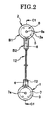
- FIG. 2 illustrates a right side view of the cable moving member operation device in FIG. 1
- the cable moving member operation device includes a first pulley supporting member 1 and a second pulley supporting member 2 as shown in FIGs. 1, 2.
- the first pulley supporting member 1 includes a supporting member body 1a and a cover member 1b.
- the second pulley supporting member 2 includes a supporting member body 2a and a cover member 2b.
- the supporting member body 2a includes a pulley supporting portion B1 and a cable retaining portion B2 as illustrated in FIGs. 1, 2.
- a circular pulley placement space 3 and a cable retaining hole 4 are formed between the supporting member body 1a and the cover member 1b.
- a circular pulley placement space 5 is formed between the pulley supporting portion B1 of the supporting member body 2a and the cover member 2b.
- a cable retaining hole 6 having a square hole shape is formed between the cable retaining portion B2 of the supporting member body 2a and the cover member 2b.
- the cable retaining portion B2 of supporting member body 2a is formed in a U-shape in cross-section comprising side walls 2a1, 2a2 opposed to each other and a linking wall 2a3 for linking the side walls 2a1, 2a2.
- a circular arc groove 2a4 which faces the substantial center between the side walls 2a1, 2a2 and extends in a direction that the cable retaining hole 6 extends
- a key groove 2a5 which opens in the center of circular are groove 2a4 and is disposed to extend in a direction that the circular shape groove 2a4 extends, are formed in the linking wall 2a3 for linking the side walls.
- a circular arc groove 2b1 opposed to the circular arc groove 2a4 is formed in the cover member 2b.
- a driven pulley 7 is rotatably disposed in the pulley placement space 3, and a driving pulley 8 is rotatably disposed in the pulley placement space 5.
- a pulley shaft (rotation shaft) 7a integrated with the driven pulley 7 is retained by the supporting member body 1a and the cover member 1b in a rotatable manner and a pulley shaft (rotation shaft) 8a integrated with the driving pulley (operation pulley) 8 is retained by the supporting member body 2a and the cover member 2b in a rotatable manner.
- the second pulley supporting member 2 is disposed in an instrument panel (not shown) of vehicle, for example.
- a rotary knob for adjusting temperature (not shown) is attached to the pulley shaft 8a retained by the second pulley supporting member 2.
- This rotary knob (not shown) is provided in the instrument panel of vehicle or the like, so as to be operatable in the vehicle interior.
- first pulley supporting member 1 is attached to a body of vehicular air-conditioning device (not shown).
- the air-mix door (moving member) of vehicular air-conditioning device interlocks with the pulley shaft 7a retained by the first pulley supporting member 1.
- two cable winding grooves 9, 10 are formed in the driven pulley 7 as shown in FIG. 3.
- a locking hole 9a having a cutout circle shape, which opens up to one side face 7a and the cable winding groove 9, and a locking hole 10a having a cutout circle shape (the same as the locking hole 9a), which opens up to the other side face 7c and the cable winding groove 10, are formed in the driven pulley 7 as illustrated in FIG. 3 (reference to FIGs. 4, 5). As illustrated in FIGs.
- first virtual line L1 a line connecting the center of locking hole 9a with the center of driven pulley 7
- second virtual line L2 a line connecting the center of locking hole 10a with the center of driven pulley 7
- Two cable winding grooves 9', 10' are formed in the driving pulley 8 as shown in FIG. 3. Also, a locking hole 9a having a cutout circle shape, which opens up to one side face 8b and the cable winding groove 9', and a locking hole 10a' having a cutout circle shape (the same as the locking hole 9a'), which opens up to the other side face 8c and the cable winding groove 10', are formed in the driving pulley 8 as shown in FIG. 3 (reference to FIGs. 4, 5). As illustrated in FIGs.
- first virtual line L1' a line connecting the center of locking hole 9a' and the center of driving pulley 8 is adopted as a first virtual line L1' and a line connecting the center of locking hole 10a' and the center of driving pulley 8 is adopted as a second virtual line L2'.
- An angle between the first virtual line L1' and the second virtual line L2' is set about 120° on a sharp angle side.
- the cable moving member operation device includes a tubular outer cable 12 made of a flexible resin as a cable retaining member.
- One end portion 12a of the outer cable 12 is disposed in the vicinity of the driven pulley 7 and also is fastened (held) into the cable supporting hole 4 of the first pulley supporting member 1.
- the outer cable as illustrated in FIGs. 7-10, includes two cable insertion holes 13, 14 each of which opens up to the both ends in the longitudinal direction.
- a control cable 15 is inserted into the cable insertion hole 13 and a control cable 16 is inserted into the cable insertion hole 14.
- Each of the control cables 15, 16 comprises a twisted wire or the like which is formed by twisting a number of piano wires.
- a cylindrical shaft to be locked 15a is integrated with one end portion of the control cable 15 as illustrated in FIGs. 3, 4.
- a cylindrical shaft to be locked16a is integrated with one end portion of the control cable 16 as illustrated in FIGs. 3, 5.
- the shaft 15a is fitted to the locking hole 9a having a cutout circle shape in a rotatable manner and in a non-lockable manner in the radial direction as shown in FIG. 4.
- the locked shaft 16a is fitted to the locking hole 10a having a cutout circle shape in a rotatable manner and in a non-lockable manner in the radial direction as shown in FIG. 5.
- One end portion sides of the control cables 15, 16 are wound to the cable winding grooves 9, 10, respectively, at about half around toward directions opposite to each other.
- shafts to be locked 15a', 16a are disposed in the other end portions of the control cables 15, 16, respectively, and the shafts 15a', 16a' are fitted to the locking holes 9a', 10a' each having a cutout circle shape, respectively, as shown in FIGs. 4, 5, in a rotatable manner and in a non-lockable manner in the radial direction.
- the other end portion sides of the control cables 10, 11 are wound to the cable winding grooves 9', 10', respectively, at about half around toward directions opposite to each other.
- the other end portion 12b of outer cable 12 is inserted into an insertion hole 17a of a spring receiving member 17 made of a resin.
- the spring receiving member 17 is fastened to the other end portion 12b of outer cable 12 by bonding or heat sealing, and also inserted into the cable retaining hole 6 of the second supporting member 2 in a movable manner.
- a spring receiving wall 6a is provided in the supporting member body 2a of the second supporting member 2.
- the spring receiving wall 6a is located at the end of the cable retaining hole 6 on the pulley placement space 5 side as shown in FIGs. 4, 5.
- a guide hole 6b is formed in the spring receiving wall 6b, which opens up to the pulley placement space 5 and the cable retaining hole 6.
- the guide hole 6 is formed to become a circular arc shape toward the pulley placement space 5 side.
- Each of the other end sides of the control cables 15, 16 is inserted to the pulley placement space 5 side via the guide hole 6b, and 8 then is wound to each of the cable winding grooves 9', 10' of the driving pulley 8 as described above.
- the spring receiving member 17, as shown in FIGs. 7, 8, includes a rectangular column portion 18 disposed in the cable retaining hole 6 in a movable manner in a direction that the control cables 15, 16 extend, and a cylindrical spring retaining projection 19 integrated with the rectangular column portion 18 as shown in FIGs. 6, 8-10.
- the spring retaining projection 19 is disposed in the center of an end face (spring bearing face) 18f of the rectangular column portion 18 to project from the end face 18f positioned on the spring receiving side 6 toward the spring receiving wall 6a.
- the rectangular column portion 18 includes side walls 18a, 18b, which engage with an inner face 2a31 of the linking wall 2a3 of the supporting member body 2a and an inner face 2b2 of the cover member 2b, respectively, in a slidable manner or face at intervals the inner face 2a31 of linking wall 2a3 of the supporting member body 2a and the inner face 2b2 of the cover member 2b, respectively, and side faces 18c, 18d, which face at intervals the side walls 2a1, 2a2 of the supporting member body 2a, respectively.
- a projection (key) 18e which engages with the key groove 2a5 of linking wall 2a3 in a slidable manner is integrally formed in the side face 18a of the rectangular column portion 18.
- the projection 18e is formed along the rectangular column portion.
- the rectangular column portion 18 is thereby controlled so as not to approach and separate relative to the side walls 2a1, 2a2, and the intervals between the rectangular column portion 18 and the side walls 2a1, 2a2 arc accordingly stabilized.
- a coil spring 20 is disposed between the end face (spring receiving face) 18f of the rectangular column portion 18 and the spring receiving wall 6a as a biasing device.
- the spring retaining projection 19 is inserted into the coil spring 20 and also the control cables 15, 16 are inserted to the coil spring 20. Accordingly, the other end portion 12b of the outer cable 12 and the spring receiving member 17 are biased by the coil spring 20 toward one end side of the outer cable 12; thus, the sagging of control cables 15, 16 is eliminated.
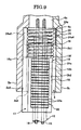
- a ratchet mechanism 21 as illustrated in FIGs. 6-10 is disposed between the cable retaining portion B2 and the rectangular column portion 18.
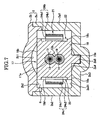
- This ratchet mechanism 21 includes locking tooth rows 22, 23 and a ratchet pawl member 24 comprising a flat spring.
- the locking tooth row 22 includes a number of locking teeth 22a arranged in saw-tooth appearance at equal pitches in the longitudinal direction of the outer cable 12.
- the locking tooth row 23 includes a number of locking teeth 23a arranged in saw-tooth appearance at equal pitches in the longitudinal direction of outer cable 12.
- each of the locking teeth 22a includes a locking face 22a1 and an engaging face 22a2, and each of the locking teeth 23a includes a locking face 23a1 and an engaging face 23a2.
- An inclined angle ⁇ of the locking face 22a1 relative to the face orthogonal to the side face 18c is about 10°.
- An inclined angle ⁇ of the engaging face 22a2 relative to the side face 18d is about 30°,
- An inclined angle ⁇ of the locking face 23a1 relative to the face orthogonal to the side face 18d is about 10°.
- An inclined angle ⁇ of the engaging face 23a2 relative to the side face 18d is about 30°.
- the inclined angles ⁇ , ⁇ are 10 not limited to those values.
- locking holes 2h1, 2h2, which are located on the portions of side wall 2a1, 2a2 sides, respectively, and on the spring receiving wall 6a side to open up to the cable retaining hole 6, are formed in the linking wall 2a3 of the supporting member body 2a.
- the ratchet pawl member 24 includes a plate-like base 24a and ratchet pawls 24b, 24c as shown in FIG. 11.
- the plate-like base 24a is formed in substantial U-shape comprising opposed plate portions 24a1, 24a2 and a linking plate portion 24a3 integrated with one end of each of the opposed plate portions 24a1, 24a2.
- opposed plate portion 24a1 is fitted to the locking hole 2h1 of the linking wall 2a3 and the other end portion of opposed plate portion 24a2 is fitted to the locking hole 2h2 of the linking wall 2a3 as illustrated in FIG. 8.
- the opposed plate portion 24a1 has contact with the side walls 2a1 of the supporting member body 2a and the opposed plate portion 24a2 has contact with the side wall 2a2 of the supporting member body 2a.
- a projection 24a4 which swells in a circular arc shape on a side opposite between the opposed plate portions 24a1, 24a2, is formed in the linking plate portion 24a3.
- the projection 24a4 has contact with a circular arc groove 2b1 of the cover member 2b.
- the ratchet pawl 24b includes an inclined arm portion 24b1 and a pawl portion 24b2 linked to the leading edge of inclined arm portion 24b1.
- the ratchet pawl 24c includes an inclined arm portion 24c1 and a pawl portion 24c2 linked to the leading end of the inclined arm portion 24c1.
- the inclined arm portion 24b1 and the inclined arm portion 24c1 incline 11 in a direction coming close to each other.
- the leading end portions of the pawl portions 24b2, 24c2 face the locking tooth rows 22, 23, respectively, in about the same depth positions in the depth direction of the cable supporting hole 6.
- the leading end portion of the pawl portion 24b2 has contact with the engaging face 22a2 of one of the locking teeth 22a by own spring force, and also the leading end portion of pawl portion 24c2 has contact with the engaging face 23a2 of one of the locking teeth 23a by own spring force.
- leading ends of pawl portions 24b2, 24c2 are misaligned at P/2, about half the length (measurement) of arrangement pitch P of the locking teeth 22a, 23a (interval between apexes or interval between valleys of locking teeth 22a, interval between apexes or interval between valleys of locking teeth 23a) in the depth direction of cable retaining hole 6. More particularly, if the arrangement pitch of locking teeth 22a, 23a is 1mm, the leading ends of pawl portions 24b2, 24c2 are misaligned at 0.5mm in the depth direction.
- the pawl portion 24b2 of ratchet pawl 24b is locked to the locking face 22a1 of a number of locking teeth 22a, and the pawl portion 24c2 of ratchet pawl 24c is floated at 1/2 pitch (P/2) from the locking face 23a1 of a number of locking teeth 23a.
- the pawl portion 24c3 of ratchet pawl 24c is locked to the locking face 23a1 of a number of locking teeth 23a
- the pawl portion 24b of ratchet pawl 24b is floated at 1/2 pitch (P/2) from the locking face 22a1 of a number of the locking teeth 22a.
- the pawl portions 24b2, 24c2 are alternately locked to the locking faces 22a1, 23a1 as described above.
- the stretching amount along the temperature change and temporal change of the resin outer cable 12 is larger than the stretch of control cables 15, 16 at single digit.
- the control cables 15, 16 tend to sag.
- the spring receiving member 17 is moved to the opening end side (one end side of outer cable 12) of cable retaining hole 6 by the coil spring 20, and the other end portion 12b of outer cable 12 is moved toward one end side of the outer cable 12; thus, the sagging of control cables 15, 16 is eliminated.
- the pawl portion 24b2 of ratchet pawl 24b is locked to the locking face 22a1 of one of the locking teeth 22a of the locking teeth row 22, or the pawl portion 24c2 of the ratchet pawl 24c is locked to the locking face 23a1 of one of the locking teeth 23a of the locking tooth row 23.
- the other end portion 12b of outer cable 12 is prevented from moving to the spring receiving wall 6a side. Such movement is prevented every half pitch (1/2) of the arrangement pitch P of locking tooth rows 22, 23. If the control cables 15, 16 stretch, the movement can be controlled every stretching measurement.
- the cable moving member operation device comprises the operation pulley (driving pulley 8), the driven pulley 7 for interlocking with the moving member (air-mix door), the flexible tubular outer cable (12) having both end portions disposed in the vicinity of both of the pulleys (7, 8), respectively, the control cable (15, 16) inserted into the outer cable in a slidable manner for transferring rotation of the operation pulley (driving pulley 8) to the driven pulley 7, the first supporting portion (cable retaining hole 4) for supporting one end portion 12a of the outer cable 12 in the vicinity of one of the pulleys (driven pulley 7), a second supporting portion (cable retaining hole B2) located in the vicinity of the other (driving pulleys 8) of the pulleys (7, 8) for supporting the other end portion 12b of the outer cable 12 in a movable manner in a longitudinal direction, and a biasing device (coil spring 20) configured to bias the
- the ratchet mechanism 21 for preventing the other end portion 12b of the outer cable 12 from moving to a direction opposite to a biasing direction by the biasing device (coil spring 20) is disposed between the other end portion 12b of the outer cable 12 and the second supporting portion (cable retaining portion B2).
- the ratchet mechanism 21 prevents the other end portion 12b of outer cable 12 from moving in a direction opposite to the biasing direction by the biasing device (coil spring 20).
- control cable with the contraction of outer cable can be securely prevented.
- the ratchet mechanism 21 includes the locking teeth row 22, 23 provided in the other end portion of the outer cable, having a number of locking teeth 22a, 23a arranged in a saw-tooth appearance in the longitudinal direction of the outer cable, and a plurality of ratchet pawls 24b, 24c retained by the second supporting portion (cable retaining portion B2), each having the leading end portion for engaging with any one of the number of locking teeth 22a, 23a, and the leading end portions of the plurality of ratchet pawls 24b, 24c have positions misaligned in the longitudinal direction of the outer cable 12, such that the leading end portions of the ratchet pawls 24b, 24c engage with the locking teeth 22a, 23a in series.
- the moving control with fine dimension can be performed by the simple structure.
- the second supporting portion (cable retaining member B2) includes the cable retaining hole 6 having the pawl supporting walls (side walls 2a1, 2a2) opposed to each other, the other end portion 12b of the outer cable 12 is disposed in the cable retaining hole 6, and the plurality of ratchet pawls 24b, 24c is formed by a plate spring and includes the plate-like base 24a having contact with the inner faces of the pawl supporting walls (side walls 2a1, 2a2).
- the plurality of ratchet pawls 24b, 24c are stably supported.
- the biasing device comprises the coil spring 20 disposed between the end wall (spring receiving wall 6a) of the cable retaining hole 6 and the other end portion 12b of the outer cable 12 opposed to the end wall (spring receiving wall 6a).
- the cable retaining hole 6 has the linking wall 2a3 for linking the pawl supporting walls (side walls 2a1, 2a2) opposed to each other, and the linking wall 2a3 includes the circular arc groove 2a4 forming a space for disposing the coil spring.
- the cable retaining member B2 can be downsized
- the linking wall 2a3 includes the guide groove (key groove 2a5) extending parallel to an axis line of the other end portion 12b of the outer cable 12, and the guide projection (projection 18e) engaging with the guide groove (key groove 2a5) in a slidable manner is integrally formed in the other end portion 12b of the outer cable 12.
- the movement of the other end portion 12b of the outer cable 12 in a direction crossing with the outer cable is controlled, so the ratchet mechanism 21 can be prevented from being disabled.
Landscapes
- Engineering & Computer Science (AREA)
- General Engineering & Computer Science (AREA)
- Health & Medical Sciences (AREA)
- Oral & Maxillofacial Surgery (AREA)
- Mechanical Engineering (AREA)
- Air-Conditioning For Vehicles (AREA)
- Flexible Shafts (AREA)
Abstract
A cable moving member operation device includes an operation pulley, a driven pulley (8) for interlocking with a moving member, a outer cable (12) having both end portions disposed in the vicinity of both of the pulleys, respectively, a control cable (15,16) inserted into the outer cable for transferring rotation of the operation pulley to the driven pulley, a first supporting portion (4) for supporting one end portion (12a) of the outer cable in the vicinity of one of the pulleys, a second supporting portion (B2) located in the vicinity of the other of the pulleys for supporting the other end portion of the outer cable in a longitudinal direction, a biasing device (20) for biasing the other end portion (12b) of the outer cable (12) to one end portion (12a) of the outer cable, and a ratchet mechanism (21) for preventing the other end portion (12b) of the outer cable from moving in a direction opposite to a biasing direction.
Description
- The present invention relates to a cable moving member operation device configured to operate a moving member by using a control cable.
- A vehicular air-conditioning device installed in, for example, an automobile, includes a rotary door (moving member) for adjusting an opening degree of an air mass opening of a heater unit and also a rotary knob for switching a blowing mode to a vehicle interior. A cable moving member operation device is known for mechanically transferring the turning of rotary knob to the rotary door via a control cable.
- The cable moving member operation device includes an operation pulley which rotates relative to the turning of rotary knob, a driving pulley provided in a rotation shaft of the rotary door and a flexible cable which interlocks both of the pulleys.
- The flexible cable comprises a pair of flexible tubular outer cables (made of resin) and control cables each of which is inserted into each of the outer cables in a slidable manner. The both end portions of each of the outer cables are retained by first and second supporting members, respectively, in the vicinity of both of the pulleys. The both end portions of each of the control cables are wound around both of the pulleys and retained by both of the pulleys.
- Each of the control cables generally comprises a member having flexibility, for example, a twisted wire comprising a number of steel wires, such that its slidability does not deteriorate when bending on the way of path.
- However, the twisted wire has a property which tightens and stretches by repeatedly pulling the wire. If the control cables stretches, allowance is produced between the both end portions of the control cables and the pulleys; thus, the rotation of the operation pulley is not well transferred to the driving pulley.
- In order to solve the above problem, there is a known cable moving member operation device configured to eliminate the deflection caused by the stretching of control cables by means of retaining one end portion of an outer cable to a first supporting portion and retaining the other end portion of the outer cable to a second supporting portion in a movable manner in the longitudinal direction, and also biasing the other end portion of the outer cable toward one end portion of the outer cable by a sagging protection spring (for example
JP2004-210188A - However, in case that the load from the moving member is large, if the spring force of sagging protection spring is not larger than the load, the other end portion of outer cable is pushed back against the spring force of sagging protection spring by the operation force, and it is considered that the operation force is not accurately transferred to the moving member.
- In addition, since the outer cable is made of a resin, it has the stretching amount much larger than that of the control cable made of copper wires. Accordingly, a problem is caused, which is similar to the case that the control cables are stretched by the contraction of outer cable.
- It is, therefore, an object of the present invention to provide, regardless of size of load by a moving member and size of a biasing force of a biasing device for sagging protection, which biases an end portion of outer cable, a cable moving member operation device, which can prevent the end portion of outer cable from being pushed back in a direction opposite to a biasing direction by an operation force and can securely prevent a control cable from sagging with the contraction of outer cable.
- In order to achieve the above object, the present invention is directed to a cable moving member operation device, comprising: an operation pulley; a driven pulley for interlocking with a moving member; a flexible tubular outer cable, both end portions thereof being disposed in the vicinity of both of the pulleys, respectively; a control cable inserted into the outer cable in a slidable manner for transferring rotation of the operation pulley to the driven pulley; a first supporting portion for supporting one end portion of the outer cable in the vicinity of one of the pulleys; a second supporting portion located in the vicinity of the other of the pulleys for supporting the other end portion of the outer cable in a movable manner in a longitudinal direction; and a biasing device configured to bias the other end portion of the outer cable to one end portion of the outer cable, wherein a ratchet mechanism for preventing the other end portion of the outer cable from moving in a direction opposite to a biasing direction by the biasing device is disposed between the other end portion of the outer cable and the second supporting portion.
-
- FIG. 1 is a lateral view showing a cable moving member operation device according to the present invention.
- FIG. 2 is a right lateral view showing the cable moving member operation device in FIG. 1.
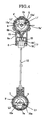
- FIG. 3 is a cross-section view along C1-C1 line in FIG. 2.
- FIG. 4 is a partial cross-section view along D1-D1 line in FIG. 3.
- FIG. 5 is a partial cross-section view long D2-D2 line in FIG. 3.
- FIG. 6 is a cross-section view along A1-A1 line in FIG. 1.
- FIG. 7 is a cross-section view along A2-A2 line in FIG. 6.
- FIG. 8 is a cross-section view along A3-A3 line in FIG. 6.
- FIG. 9 is a partial cross-section view of a second pulley supporting member along A4-A4 line in FIG. 8.
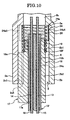
- FIG. 10 is a cross-section view along A4-A4 line in FIG. 8.
- FIG. 11 is a perspective view of a ratchet pawl member shown in FIGs. 6-10.
- Hereinbelow, an embodiment of the present invention will be explained with reference to the drawings.
- FIG. 1 illustrates a cable moving member operation device used for opening and closing operation of an air-mix door (moving member) or the like provided in a vehicular air-conditioning device (not shown), for example. FIG. 2 illustrates a right side view of the cable moving member operation device in FIG. 1
- The cable moving member operation device includes a first
pulley supporting member 1 and a secondpulley supporting member 2 as shown in FIGs. 1, 2. - The first
pulley supporting member 1 includes a supportingmember body 1a and acover member 1b. The secondpulley supporting member 2 includes a supportingmember body 2a and acover member 2b. In addition, the supportingmember body 2a includes a pulley supporting portion B1 and a cable retaining portion B2 as illustrated in FIGs. 1, 2. - A circular
pulley placement space 3 and acable retaining hole 4 are formed between the supportingmember body 1a and thecover member 1b. A circularpulley placement space 5 is formed between the pulley supporting portion B1 of the supportingmember body 2a and thecover member 2b. Acable retaining hole 6 having a square hole shape is formed between the cable retaining portion B2 of the supportingmember body 2a and thecover member 2b. - Moreover, the cable retaining portion B2 of supporting
member body 2a is formed in a U-shape in cross-section comprising side walls 2a1, 2a2 opposed to each other and a linking wall 2a3 for linking the side walls 2a1, 2a2. Furthermore, a circular arc groove 2a4, which faces the substantial center between the side walls 2a1, 2a2 and extends in a direction that thecable retaining hole 6 extends, and a key groove 2a5, which opens in the center of circular are groove 2a4 and is disposed to extend in a direction that the circular shape groove 2a4 extends, are formed in the linking wall 2a3 for linking the side walls. A circular arc groove 2b1 opposed to the circular arc groove 2a4 is formed in thecover member 2b. - A driven
pulley 7 is rotatably disposed in thepulley placement space 3, and adriving pulley 8 is rotatably disposed in thepulley placement space 5. In addition, a pulley shaft (rotation shaft) 7a integrated with the drivenpulley 7 is retained by the supportingmember body 1a and thecover member 1b in a rotatable manner and a pulley shaft (rotation shaft) 8a integrated with the driving pulley (operation pulley) 8 is retained by the supportingmember body 2a and thecover member 2b in a rotatable manner. - Moreover, the second
pulley supporting member 2 is disposed in an instrument panel (not shown) of vehicle, for example. A rotary knob for adjusting temperature (not shown) is attached to thepulley shaft 8a retained by the secondpulley supporting member 2. This rotary knob (not shown) is provided in the instrument panel of vehicle or the like, so as to be operatable in the vehicle interior. - Furthermore, the first
pulley supporting member 1 is attached to a body of vehicular air-conditioning device (not shown). For example, the air-mix door (moving member) of vehicular air-conditioning device (not shown) interlocks with thepulley shaft 7a retained by the firstpulley supporting member 1. - Moreover, two
cable winding grooves pulley 7 as shown in FIG. 3. Also, alocking hole 9a having a cutout circle shape, which opens up to oneside face 7a and thecable winding groove 9, and alocking hole 10a having a cutout circle shape (the same as thelocking hole 9a), which opens up to the other side face 7c and thecable winding groove 10, are formed in the drivenpulley 7 as illustrated in FIG. 3 (reference to FIGs. 4, 5). As illustrated in FIGs. 4, 5, a line connecting the center oflocking hole 9a with the center of drivenpulley 7 is adopted as a first virtual line L1, and a line connecting the center oflocking hole 10a with the center of drivenpulley 7 is adopted as a second virtual line L2. An angle between the first virtual line L1 and the second virtual line L2 is set about 120° on the sharp angle side. - Two cable winding grooves 9', 10' are formed in the
driving pulley 8 as shown in FIG. 3. Also, alocking hole 9a having a cutout circle shape, which opens up to oneside face 8b and the cable winding groove 9', and alocking hole 10a' having a cutout circle shape (the same as thelocking hole 9a'), which opens up to theother side face 8c and the cable winding groove 10', are formed in thedriving pulley 8 as shown in FIG. 3 (reference to FIGs. 4, 5). As illustrated in FIGs. 4, 5, a line connecting the center oflocking hole 9a' and the center of drivingpulley 8 is adopted as a first virtual line L1' and a line connecting the center oflocking hole 10a' and the center of drivingpulley 8 is adopted as a second virtual line L2'. An angle between the first virtual line L1' and the second virtual line L2' is set about 120° on a sharp angle side. - As illustrated in FIGS. 1, 2, the cable moving member operation device includes a tubular
outer cable 12 made of a flexible resin as a cable retaining member. Oneend portion 12a of theouter cable 12 is disposed in the vicinity of the drivenpulley 7 and also is fastened (held) into thecable supporting hole 4 of the firstpulley supporting member 1. - The outer cable, as illustrated in FIGs. 7-10, includes two
cable insertion holes control cable 15 is inserted into thecable insertion hole 13 and acontrol cable 16 is inserted into thecable insertion hole 14. Each of thecontrol cables - A cylindrical shaft to be locked 15a is integrated with one end portion of the
control cable 15 as illustrated in FIGs. 3, 4. A cylindrical shaft to be locked16a is integrated with one end portion of thecontrol cable 16 as illustrated in FIGs. 3, 5. Theshaft 15a is fitted to thelocking hole 9a having a cutout circle shape in a rotatable manner and in a non-lockable manner in the radial direction as shown in FIG. 4. The lockedshaft 16a is fitted to thelocking hole 10a having a cutout circle shape in a rotatable manner and in a non-lockable manner in the radial direction as shown in FIG. 5. One end portion sides of thecontrol cables cable winding grooves - In addition, shafts to be locked 15a', 16a are disposed in the other end portions of the
control cables shafts 15a', 16a' are fitted to the lockingholes 9a', 10a' each having a cutout circle shape, respectively, as shown in FIGs. 4, 5, in a rotatable manner and in a non-lockable manner in the radial direction. The other end portion sides of thecontrol cables 10, 11 are wound to the cable winding grooves 9', 10', respectively, at about half around toward directions opposite to each other. - The
other end portion 12b ofouter cable 12 is inserted into aninsertion hole 17a of aspring receiving member 17 made of a resin. Thespring receiving member 17 is fastened to theother end portion 12b ofouter cable 12 by bonding or heat sealing, and also inserted into thecable retaining hole 6 of the second supportingmember 2 in a movable manner. - A
spring receiving wall 6a is provided in the supportingmember body 2a of the second supportingmember 2. Thespring receiving wall 6a is located at the end of thecable retaining hole 6 on thepulley placement space 5 side as shown in FIGs. 4, 5. Aguide hole 6b is formed in thespring receiving wall 6b, which opens up to thepulley placement space 5 and thecable retaining hole 6. Theguide hole 6 is formed to become a circular arc shape toward thepulley placement space 5 side. Each of the other end sides of thecontrol cables pulley placement space 5 side via theguide hole pulley 8 as described above. - The
spring receiving member 17, as shown in FIGs. 7, 8, includes arectangular column portion 18 disposed in thecable retaining hole 6 in a movable manner in a direction that thecontrol cables spring retaining projection 19 integrated with therectangular column portion 18 as shown in FIGs. 6, 8-10. Thespring retaining projection 19 is disposed in the center of an end face (spring bearing face) 18f of therectangular column portion 18 to project from theend face 18f positioned on thespring receiving side 6 toward thespring receiving wall 6a. - As shown in FIGs. 6, 7, the
rectangular column portion 18 includesside walls member body 2a and an inner face 2b2 of thecover member 2b, respectively, in a slidable manner or face at intervals the inner face 2a31 of linking wall 2a3 of the supportingmember body 2a and the inner face 2b2 of thecover member 2b, respectively, and side faces 18c, 18d, which face at intervals the side walls 2a1, 2a2 of the supportingmember body 2a, respectively. - A projection (key) 18e which engages with the key groove 2a5 of linking wall 2a3 in a slidable manner is integrally formed in the
side face 18a of therectangular column portion 18. Theprojection 18e is formed along the rectangular column portion. Therectangular column portion 18 is thereby controlled so as not to approach and separate relative to the side walls 2a1, 2a2, and the intervals between therectangular column portion 18 and the side walls 2a1, 2a2 arc accordingly stabilized. - As shown in FIGs. 6, 9, 10, a
coil spring 20 is disposed between the end face (spring receiving face) 18f of therectangular column portion 18 and thespring receiving wall 6a as a biasing device. Thespring retaining projection 19 is inserted into thecoil spring 20 and also thecontrol cables coil spring 20. Accordingly, theother end portion 12b of theouter cable 12 and thespring receiving member 17 are biased by thecoil spring 20 toward one end side of theouter cable 12; thus, the sagging ofcontrol cables - Moreover, a
ratchet mechanism 21 as illustrated in FIGs. 6-10 is disposed between the cable retaining portion B2 and therectangular column portion 18. - This
ratchet mechanism 21 includes lockingtooth rows ratchet pawl member 24 comprising a flat spring. As shown in FIG. 6, the lockingtooth row 22 includes a number of lockingteeth 22a arranged in saw-tooth appearance at equal pitches in the longitudinal direction of theouter cable 12. The lockingtooth row 23 includes a number of lockingteeth 23a arranged in saw-tooth appearance at equal pitches in the longitudinal direction ofouter cable 12. - As shown in FIG. 6, each of the locking
teeth 22a includes a locking face 22a1 and an engaging face 22a2, and each of the lockingteeth 23a includes a locking face 23a1 and an engaging face 23a2. An inclined angle α of the locking face 22a1 relative to the face orthogonal to theside face 18c is about 10°. An inclined angle β of the engaging face 22a2 relative to theside face 18d is about 30°, An inclined angle α of the locking face 23a1 relative to the face orthogonal to theside face 18d is about 10°. An inclined angle β of the engaging face 23a2 relative to theside face 18d is about 30°. In addition the inclined angles α, β are 10 not limited to those values. - As shown in FIG. 8, locking holes 2h1, 2h2, which are located on the portions of side wall 2a1, 2a2 sides, respectively, and on the
spring receiving wall 6a side to open up to thecable retaining hole 6, are formed in the linking wall 2a3 of the supportingmember body 2a. - Moreover, the
ratchet pawl member 24 includes a plate-like base 24a and ratchetpawls like base 24a is formed in substantial U-shape comprising opposed plate portions 24a1, 24a2 and a linking plate portion 24a3 integrated with one end of each of the opposed plate portions 24a1, 24a2. - The other end portion of opposed plate portion 24a1 is fitted to the locking hole 2h1 of the linking wall 2a3 and the other end portion of opposed plate portion 24a2 is fitted to the locking hole 2h2 of the linking wall 2a3 as illustrated in FIG. 8. Moreover, the opposed plate portion 24a1 has contact with the side walls 2a1 of the supporting
member body 2a and the opposed plate portion 24a2 has contact with the side wall 2a2 of the supportingmember body 2a. Furthermore, a projection 24a4, which swells in a circular arc shape on a side opposite between the opposed plate portions 24a1, 24a2, is formed in the linking plate portion 24a3. The projection 24a4 has contact with a circular arc groove 2b1 of thecover member 2b. - As illustrated in FIG. 11, the
ratchet pawl 24b includes an inclined arm portion 24b1 and a pawl portion 24b2 linked to the leading edge of inclined arm portion 24b1. Also, as illustrated in FIG. 11, theratchet pawl 24c includes an inclined arm portion 24c1 and a pawl portion 24c2 linked to the leading end of the inclined arm portion 24c1. The inclined arm portion 24b1 and the inclined arm portion 24c1 incline 11 in a direction coming close to each other. - The leading end portions of the pawl portions 24b2, 24c2 face the locking
tooth rows cable supporting hole 6. The leading end portion of the pawl portion 24b2 has contact with the engaging face 22a2 of one of the lockingteeth 22a by own spring force, and also the leading end portion of pawl portion 24c2 has contact with the engaging face 23a2 of one of the lockingteeth 23a by own spring force. - Furthermore, the leading ends of pawl portions 24b2, 24c2 are misaligned at P/2, about half the length (measurement) of arrangement pitch P of the locking
teeth teeth 22a, interval between apexes or interval between valleys of lockingteeth 23a) in the depth direction ofcable retaining hole 6. More particularly, if the arrangement pitch of lockingteeth - As a result, in FIG. 6, the pawl portion 24b2 of
ratchet pawl 24b is locked to the locking face 22a1 of a number of lockingteeth 22a, and the pawl portion 24c2 ofratchet pawl 24c is floated at 1/2 pitch (P/2) from the locking face 23a1 of a number of lockingteeth 23a. In addition, when the pawl portion 24c3 ofratchet pawl 24c is locked to the locking face 23a1 of a number of lockingteeth 23a, thepawl portion 24b ofratchet pawl 24b is floated at 1/2 pitch (P/2) from the locking face 22a1 of a number of the lockingteeth 22a. Accordingly, the pawl portions 24b2, 24c2 are alternately locked to the locking faces 22a1, 23a1 as described above. - Next, operation of the cable moving member operation device having the above structure will be explained.
- If the rotary knob (not shown) is turned to rotate the driving
pulley 8, the rotation of drivingpulley 8 is transferred to the drivenpulley 7 via thecontrol cables pulley 7, is opened and closed, and the air which is blasted from an air outlet (not shown) of the vehicular air-conditioning device is accordingly adjusted. - When the
control cables spring receiving member 17 is moved to the opening end side of cable retaining hole 6 (one end side of outer cable 12) by thecoil spring 20, and theother end portion 12b is moved to one end side ofouter cable 12; thus, the sagging ofcontrol cables - In addition to the above stretch of the
control cables outer cable 12 is larger than the stretch ofcontrol cables outer cable 12 is contracted, thecontrol cables spring receiving member 17 is moved to the opening end side (one end side of outer cable 12) ofcable retaining hole 6 by thecoil spring 20, and theother end portion 12b ofouter cable 12 is moved toward one end side of theouter cable 12; thus, the sagging ofcontrol cables - In operation of vehicular air-conditioning device, depending on the rotation direction of air-mix door (not shown), the load for rotating the air-mix door sometimes becomes larger than the spring force of
coil spring 20 by the air flow acting on the air-mix door or the like. 13 - Due to the above load, the
other end portion 12b ofouter cable 12 tends to move to thespring receiving wall 6a side against the spring force ofcoil spring 20 along the turning of rotary knob. - In this case, the pawl portion 24b2 of
ratchet pawl 24b is locked to the locking face 22a1 of one of the lockingteeth 22a of the lockingteeth row 22, or the pawl portion 24c2 of theratchet pawl 24c is locked to the locking face 23a1 of one of the lockingteeth 23a of the lockingtooth row 23. Thus, theother end portion 12b ofouter cable 12 is prevented from moving to thespring receiving wall 6a side. Such movement is prevented every half pitch (1/2) of the arrangement pitch P of lockingtooth rows control cables - As described above, if the load for rotating the air-mix door becomes larger than the spring force of
coil spring 20, the sagging ofcontrol cables other end portion 12b of theouter cable 12 to thespring receiving wall 6a side when turning the rotary knob. Therefore, the turning of rotary knob is accurately transferred to the air-mix door, and the opening degree of air-mix door can be precisely adjusted. - Furthermore, as illustrated in FIG. 6, for example, when the pawl portion 24b2 of the
ratchet pawl 24b is locked to the locking face 22a1 of the lockingteeth 22a, a force is act on the locking face 22a1 in a direction along the locking face 22a2 and also in a direction toward the center side of thespring receiving member 17 from the pawl portion 24b2. Therefore, it is possible to prevent the defect of lockingteeth 22a by the force acting between thepawl portion 24b and the locking plane 22a1 when the rotation of air mix door by the rotary knob (not shown) is 14 operated. - As described above, the cable moving member operation device according to the embodiment of the present invention comprises the operation pulley (driving pulley 8), the driven
pulley 7 for interlocking with the moving member (air-mix door), the flexible tubular outer cable (12) having both end portions disposed in the vicinity of both of the pulleys (7, 8), respectively, the control cable (15, 16) inserted into the outer cable in a slidable manner for transferring rotation of the operation pulley (driving pulley 8) to the drivenpulley 7, the first supporting portion (cable retaining hole 4) for supporting oneend portion 12a of theouter cable 12 in the vicinity of one of the pulleys (driven pulley 7), a second supporting portion (cable retaining hole B2) located in the vicinity of the other (driving pulleys 8) of the pulleys (7, 8) for supporting theother end portion 12b of theouter cable 12 in a movable manner in a longitudinal direction, and a biasing device (coil spring 20) configured to bias theother end portion 12b of theouter cable 12 to oneend portion 12a of theouter cable 12. Moreover, theratchet mechanism 21 for preventing theother end portion 12b of theouter cable 12 from moving to a direction opposite to a biasing direction by the biasing device (coil spring 20) is disposed between theother end portion 12b of theouter cable 12 and the second supporting portion (cable retaining portion B2). - According to the above structure, if the
control cable other end portion 12b ofouter cable 12 is moved to oneend portion 12a side by the biasing device (coil spring 20) according to the stretching. Even if movement force in a direction opposite to the biasing direction of the biasing device (coil spring 20) acts on theother end portion 12b ofouter cable 12 by the operation force, theratchet mechanism 21 prevents theother end portion 12b ofouter cable 12 from moving in a direction opposite to the biasing direction by the biasing device (coil spring 20). As a result, regardless of the size of load by the moving member (air mix door) and the size of biasing force of the biasing device for sagging protection, which biases the end portion of outer cable, it is possible to prevent the end portion ofouter cable 12 from being pushed back in a direction opposite to the biasing direction by the operation force. - Moreover, the sagging of control cable with the contraction of outer cable can be securely prevented.
- Moreover, in the cable moving member operation device according to the embodiment of the present invention, the
ratchet mechanism 21 includes the lockingteeth row teeth ratchet pawls teeth ratchet pawls outer cable 12, such that the leading end portions of theratchet pawls teeth - According to the above structure, the moving control with fine dimension can be performed by the simple structure.
- Furthermore, in the cable moving member operation device according to the embodiment of the present invention, the second supporting portion (cable retaining member B2) includes the
cable retaining hole 6 having the pawl supporting walls (side walls 2a1, 2a2) opposed to each other, theother end portion 12b of theouter cable 12 is disposed in thecable retaining hole 6, and the plurality ofratchet pawls like base 24a having contact with the inner faces of the pawl supporting walls (side walls 2a1, 2a2). - According to the above structure, the plurality of
ratchet pawls - In addition, in the cable moving member operation device according the embodiment of the present invention, the biasing device (coil spring 20) comprises the
coil spring 20 disposed between the end wall (spring receiving wall 6a) of thecable retaining hole 6 and theother end portion 12b of theouter cable 12 opposed to the end wall (spring receiving wall 6a). Thecable retaining hole 6 has the linking wall 2a3 for linking the pawl supporting walls (side walls 2a1, 2a2) opposed to each other, and the linking wall 2a3 includes the circular arc groove 2a4 forming a space for disposing the coil spring. - According to the above structure, the cable retaining member B2 can be downsized
- Moreover, in the cable moving member operation device according to the embodiment of the present invention, the linking wall 2a3 includes the guide groove (key groove 2a5) extending parallel to an axis line of the
other end portion 12b of theouter cable 12, and the guide projection (projection 18e) engaging with the guide groove (key groove 2a5) in a slidable manner is integrally formed in theother end portion 12b of theouter cable 12. - According to the above structure, the movement of the
other end portion 12b of theouter cable 12 in a direction crossing with the outer cable is controlled, so theratchet mechanism 21 can be prevented from being disabled. - Although the present invention has been described in terms of exemplary embodiment, it is not limited thereto. It should be appreciated that variations may be made in the embodiment described by persons skilled in the art without departing from the scope of the present invention as defined by the following claims. In addition, the number, position, shape, or the like of the component are not limited to the above embodiment, and can be changed to the number, position, shape or the like of the component preferable for conducting the present invention. Moreover, no element and component in the present disclosure is intended to be dedicated to the public regardless of whether the element or component is explicitly recited in the following claims.
Claims (5)
- A cable moving member operation device, comprising:an operation pulley (8);a driven pulley (7) for interlocking with a moving member;a flexible tubular outer cable (12) having both end portions disposed in the vicinity of both of the pulleys, respectively;a control cable (15, 16) inserted into the outer cable (12) in a slidable manner for transferring rotation of the operation pulley (8) to the driven pulley (7);a first supporting portion (4) for supporting one end portion (12a) of the outer cable (12) in the vicinity of one of the pulleys;a second supporting portion (B2) located in the vicinity of the other of the pulleys for supporting the other end portion (12b) of the outer cable in a movable manner in a longitudinal direction; anda biasing device (20) configured to bias the other end portion (12b) of the outer cable (12) to one end portion (12a) of the outer cable (12), whereina ratchet mechanism (21) for preventing the other end portion (12b) of the outer cable (12) from moving in a direction opposite to a biasing direction by the biasing device (20) is disposed between the other end portion (12b) of the outer cable and the second supporting portion (B2).
- The cable moving member operation device according to claim 1, wherein
the ratchet mechanism (21) includes a locking teeth row (22, 23) provided in the other end portion (12b) of the outer cable (12), having a number of locking teeth (22a, 23a) arranged in a saw-tooth appearance in the longitudinal direction of the outer cable, and a plurality of ratchet pawls (24b, 24c) retained by the second supporting portion (B2), each having a leading end portion for engaging with any one of the number of locking teeth, and
the leading end portions of the plurality of ratchet pawls (24b, 24c) have positions misaligned in the longitudinal direction of the outer cable, such that the leading end portions of the ratchet pawls (24b, 24c) engage with the locking teeth (22a, 23a) in series. - The cable moving member operation device according to claim 2, wherein the second supporting portion (B2) includes a cable retaining hole (6) having pawl supporting walls (2a1, 2a2) opposed to each other, the other end portion (12b) of the outer cable (12) is disposed in the cable retaining hole (6), and the plurality of ratchet pawls (24b, 24c) is formed by a plate spring and includes a plate-like base (24a) having contact with inner faces of the pawl supporting walls (2a1, 2a2).
- The cable moving member operation device according to claim 3, wherein the biasing device (20) comprises a coil spring disposed between an end wall (6a) of the cable retaining hole (6) and the other end portion (12b) of the outer cable (12) opposed to the end wall (6a), the cable retaining hole (6) has a linking wall (2a3) for linking the pawl supporting walls (2a1, 2a2) opposed to each other, and the linking wall (2a3) includes a circular arc groove (2a4) forming a space for disposing the coil spring.
- The cable moving member operation device according to claim 4, wherein the linking wall (2a3) includes a guide groove (2a5) extending parallel to an axis line of the other end portion (12b) of the outer cable (12), and a guide projection (18e) engaging with the guide groove (2a5) in a slidable manner is integrally formed in the other end portion (12b) of the outer cable (12).
Applications Claiming Priority (1)
| Application Number | Priority Date | Filing Date | Title |
|---|---|---|---|
| JP2006033256A JP2007210484A (en) | 2006-02-10 | 2006-02-10 | Cable type movable member operating device |
Publications (1)
| Publication Number | Publication Date |
|---|---|
| EP1818550A2 true EP1818550A2 (en) | 2007-08-15 |
Family
ID=38068406
Family Applications (1)
| Application Number | Title | Priority Date | Filing Date |
|---|---|---|---|
| EP07002651A Withdrawn EP1818550A2 (en) | 2006-02-10 | 2007-02-07 | Cable moving member operation device |
Country Status (3)
| Country | Link |
|---|---|
| US (1) | US20070191162A1 (en) |
| EP (1) | EP1818550A2 (en) |
| JP (1) | JP2007210484A (en) |
Cited By (2)
| Publication number | Priority date | Publication date | Assignee | Title |
|---|---|---|---|---|
| ITTO20130069A1 (en) * | 2013-01-29 | 2014-07-30 | Denso Corp | ROTARY CONTROL UNIT WITH DOUBLE CABLE, WITH CABLE VOLTAGE REGULATION |
| EP3163098A1 (en) * | 2015-10-29 | 2017-05-03 | DENSO THERMAL SYSTEMS S.p.A. | A double cable motion transmitting device adaptable to different rotation directions |
Families Citing this family (2)
| Publication number | Priority date | Publication date | Assignee | Title |
|---|---|---|---|---|
| JP5249056B2 (en) * | 2009-01-07 | 2013-07-31 | カルソニックカンセイ株式会社 | Control cable tensioning structure |
| JP7032869B2 (en) * | 2017-05-01 | 2022-03-09 | トヨフレックス株式会社 | Rope drive |
Citations (1)
| Publication number | Priority date | Publication date | Assignee | Title |
|---|---|---|---|---|
| JP2004210188A (en) | 2003-01-07 | 2004-07-29 | Tokai Rika Co Ltd | Control cable device |
Family Cites Families (5)
| Publication number | Priority date | Publication date | Assignee | Title |
|---|---|---|---|---|
| US3605520A (en) * | 1970-02-09 | 1971-09-20 | Gen Motors Corp | Cable transmission control |
| US5235866A (en) * | 1992-08-05 | 1993-08-17 | Handy And Harman Automotive Group, Inc. | Rotary temperature control device |
| US5295408A (en) * | 1992-10-09 | 1994-03-22 | Nagle Industries, Inc. | Adjustable cable strand end fitting |
| US5555769A (en) * | 1995-05-03 | 1996-09-17 | Teleflex Incorporated | Cable operated rotary control assembly |
| US5782147A (en) * | 1996-11-21 | 1998-07-21 | Hand Tool Design Corporation | Ratchet wrench having two-pawl action |
-
2006
- 2006-02-10 JP JP2006033256A patent/JP2007210484A/en not_active Withdrawn
-
2007
- 2007-02-07 EP EP07002651A patent/EP1818550A2/en not_active Withdrawn
- 2007-02-08 US US11/703,777 patent/US20070191162A1/en not_active Abandoned
Patent Citations (1)
| Publication number | Priority date | Publication date | Assignee | Title |
|---|---|---|---|---|
| JP2004210188A (en) | 2003-01-07 | 2004-07-29 | Tokai Rika Co Ltd | Control cable device |
Cited By (4)
| Publication number | Priority date | Publication date | Assignee | Title |
|---|---|---|---|---|
| ITTO20130069A1 (en) * | 2013-01-29 | 2014-07-30 | Denso Corp | ROTARY CONTROL UNIT WITH DOUBLE CABLE, WITH CABLE VOLTAGE REGULATION |
| EP2759722A1 (en) * | 2013-01-29 | 2014-07-30 | DENSO THERMAL SYSTEMS S.p.A. | Rotating control assembly with double cable, with adjustment of the cable tension |
| US9080600B2 (en) | 2013-01-29 | 2015-07-14 | Denso Thermal Systems S.P.A. | Rotating control assembly with double cable, with adjustment of the cable tension |
| EP3163098A1 (en) * | 2015-10-29 | 2017-05-03 | DENSO THERMAL SYSTEMS S.p.A. | A double cable motion transmitting device adaptable to different rotation directions |
Also Published As
| Publication number | Publication date |
|---|---|
| US20070191162A1 (en) | 2007-08-16 |
| JP2007210484A (en) | 2007-08-23 |
Similar Documents
| Publication | Publication Date | Title |
|---|---|---|
| EP1944198B1 (en) | Device for supporting cable | |
| EP1243733A1 (en) | Vehicle window lifter with cable tensioning device | |
| US7823424B2 (en) | Bicycle lock | |
| JP4442545B2 (en) | Cable support device | |
| US7494376B1 (en) | Multiple direction wire cover with positioning latch and position assurance lock | |
| EP0880633A1 (en) | Lock assembly with motorized power screw | |
| US20070191162A1 (en) | Cable moving member operation device | |
| JPH08500306A (en) | Rotary temperature controller | |
| JP4954333B2 (en) | FPC fixing structure of biaxial hinge mechanism | |
| GB2412693A (en) | Mechanical push button lock | |
| CN211524444U (en) | Electric child lock system installed in inner panel of vehicle door and vehicle thereof | |
| EP3702560A1 (en) | Automobile key operation mechanism | |
| US20230366427A1 (en) | Operating device | |
| JP2010017025A (en) | Harness wiring device for sliding door | |
| KR20180116616A (en) | Opening and closing apparstus for digital door lock | |
| JP2016216927A (en) | Lock device | |
| KR102167840B1 (en) | Latch device for vehicle | |
| EP2014490A1 (en) | Rotating control assembly with double cable | |
| US11384563B2 (en) | Spring retaining assembly for vehicle latch actuator mechanism | |
| JP2024165589A (en) | Locking device | |
| JP4378007B2 (en) | Vehicle door handle device | |
| US20220154515A1 (en) | Actuator and cable-operated drive mechanism for closure panel | |
| JP3680267B2 (en) | Reel device with door output adjustment | |
| KR100899008B1 (en) | Latch for Door Lock | |
| JP4974038B2 (en) | Door latch device |
Legal Events
| Date | Code | Title | Description |
|---|---|---|---|
| PUAI | Public reference made under article 153(3) epc to a published international application that has entered the european phase |
Free format text: ORIGINAL CODE: 0009012 |
|
| AK | Designated contracting states |
Kind code of ref document: A2 Designated state(s): AT BE BG CH CY CZ DE DK EE ES FI FR GB GR HU IE IS IT LI LT LU LV MC NL PL PT RO SE SI SK TR |
|
| AX | Request for extension of the european patent |
Extension state: AL BA HR MK YU |
|
| STAA | Information on the status of an ep patent application or granted ep patent |
Free format text: STATUS: THE APPLICATION HAS BEEN WITHDRAWN |
|
| 18W | Application withdrawn |
Effective date: 20091029 |