EP1818502A2 - Vane pump - Google Patents
Vane pump Download PDFInfo
- Publication number
- EP1818502A2 EP1818502A2 EP06380320A EP06380320A EP1818502A2 EP 1818502 A2 EP1818502 A2 EP 1818502A2 EP 06380320 A EP06380320 A EP 06380320A EP 06380320 A EP06380320 A EP 06380320A EP 1818502 A2 EP1818502 A2 EP 1818502A2
- Authority
- EP
- European Patent Office
- Prior art keywords
- suction port
- rotor
- suction
- side plate
- port
- Prior art date
- Legal status (The legal status is an assumption and is not a legal conclusion. Google has not performed a legal analysis and makes no representation as to the accuracy of the status listed.)
- Withdrawn
Links
Images



Classifications
-
- F—MECHANICAL ENGINEERING; LIGHTING; HEATING; WEAPONS; BLASTING
- F04—POSITIVE - DISPLACEMENT MACHINES FOR LIQUIDS; PUMPS FOR LIQUIDS OR ELASTIC FLUIDS
- F04C—ROTARY-PISTON, OR OSCILLATING-PISTON, POSITIVE-DISPLACEMENT MACHINES FOR LIQUIDS; ROTARY-PISTON, OR OSCILLATING-PISTON, POSITIVE-DISPLACEMENT PUMPS
- F04C2/00—Rotary-piston machines or pumps
- F04C2/30—Rotary-piston machines or pumps having the characteristics covered by two or more groups F04C2/02, F04C2/08, F04C2/22, F04C2/24 or having the characteristics covered by one of these groups together with some other type of movement between co-operating members
- F04C2/34—Rotary-piston machines or pumps having the characteristics covered by two or more groups F04C2/02, F04C2/08, F04C2/22, F04C2/24 or having the characteristics covered by one of these groups together with some other type of movement between co-operating members having the movement defined in groups F04C2/08 or F04C2/22 and relative reciprocation between the co-operating members
- F04C2/344—Rotary-piston machines or pumps having the characteristics covered by two or more groups F04C2/02, F04C2/08, F04C2/22, F04C2/24 or having the characteristics covered by one of these groups together with some other type of movement between co-operating members having the movement defined in groups F04C2/08 or F04C2/22 and relative reciprocation between the co-operating members with vanes reciprocating with respect to the inner member
- F04C2/3446—Rotary-piston machines or pumps having the characteristics covered by two or more groups F04C2/02, F04C2/08, F04C2/22, F04C2/24 or having the characteristics covered by one of these groups together with some other type of movement between co-operating members having the movement defined in groups F04C2/08 or F04C2/22 and relative reciprocation between the co-operating members with vanes reciprocating with respect to the inner member the inner and outer member being in contact along more than one line or surface
-
- F—MECHANICAL ENGINEERING; LIGHTING; HEATING; WEAPONS; BLASTING
- F01—MACHINES OR ENGINES IN GENERAL; ENGINE PLANTS IN GENERAL; STEAM ENGINES
- F01C—ROTARY-PISTON OR OSCILLATING-PISTON MACHINES OR ENGINES
- F01C21/00—Component parts, details or accessories not provided for in groups F01C1/00 - F01C20/00
- F01C21/10—Outer members for co-operation with rotary pistons; Casings
- F01C21/104—Stators; Members defining the outer boundaries of the working chamber
- F01C21/108—Stators; Members defining the outer boundaries of the working chamber with an axial surface, e.g. side plates
-
- F—MECHANICAL ENGINEERING; LIGHTING; HEATING; WEAPONS; BLASTING
- F04—POSITIVE - DISPLACEMENT MACHINES FOR LIQUIDS; PUMPS FOR LIQUIDS OR ELASTIC FLUIDS
- F04C—ROTARY-PISTON, OR OSCILLATING-PISTON, POSITIVE-DISPLACEMENT MACHINES FOR LIQUIDS; ROTARY-PISTON, OR OSCILLATING-PISTON, POSITIVE-DISPLACEMENT PUMPS
- F04C15/00—Component parts, details or accessories of machines, pumps or pumping installations, not provided for in groups F04C2/00 - F04C14/00
- F04C15/06—Arrangements for admission or discharge of the working fluid, e.g. constructional features of the inlet or outlet
Definitions
- the present invention relates to a vane pump and particularly to a vane pump whose suction efficiency and volume efficiency are improved.
- Fig. 11 is a longitudinal sectional view of the vane pump 100.
- Fig. 12 is a view of a front housing in a state seen from the left side in fig. 11.
- a side plate 103, a cam ring 104 and a rotor 105 are provided coaxially.
- a cam face 106 in the oval shape is formed on an inner face of the cam ring 104.
- the rotor 105 is mounted to a rotating shaft 107 and arranged within the cam ring 104.
- a plurality of vanes 108 are provided at the rotor 105 so that they protrude in a radial manner from the outer circumferential face of the rotor 105. With rotation of the rotor 105, the tip ends of the vanes 108 are brought into sliding contact with the cam face 106.
- a space between the outer circumferential face of the rotor 105 and the vane 108 as well as the cam face 106 is a pump chamber p.
- the pump chamber P is changed so that its volume is repeatedly expanded/contracted with the rotation of the rotor 105.
- suction ports 109, 110 are provided at the corresponding side plate 103 and rear housing 102, while at positions matching the contraction process, discharge ports 11, 112 are provided at the corresponding side plate 103.
- recesses not shown, for preventing movement of the rotor 105 in the axial direction by discharge pressure are provided at positions opposite to the discharge ports 111, 112.
- the suction ports 109, 110 are provided at the positions horizontally opposed to each other with the rotating shaft 107 interposed between them in fig. 12, and the discharge ports 111, 112 are provided in a pair so that they are vertically opposed to each other with the rotating shaft 107 interposed between them. Also, a working fluid sucked in through a suction port 113 is sucked into the pump chamber P from the two suction ports 109, 110 through a first branch passage 114 and a second branch passage 115 provided so that they are horizontally branched to two passages in the rear housing 102 arranged in the form to seal the front housing 101 as shown by a two-dotted chain line in fig. 12.
- the suction port 109 can suck the working fluid efficiently, while since the vane 108 of the rotor 105 is rotated in the same direction as the direction where the working fluid in the second branch passage 115 flows, the working fluid flowing through the second branch passage 115 can not be guided into the suction port 110 favorably, and the suction efficiency of the suction port 110 is lowered.
- Patent Document 1 Japanese Patent Application Laid-Open No. HEI 8-74750 .
- the length of the second branch passage 115 is made shorter than the length of the first branch passage 114 so as to reduce fluidity resistance of the second branch passage 115 so that the suction efficiency of the suction port 110 is improved.
- Patent Document 1 has the following problems. That is, as shown in Fig. 12, the high-pressure discharge ports 111,112 are located at positions away from a mounting portion 116 for mounting the rear housing 102 to the front housing 101. Therefore, the rear housing 102 is deformed so that it is separated from the front housing 101 by the pressure of the working fluid, on the axis passing through the high-pressure discharge ports 111, 112, and a clearance between the rear housing 102 and the rotor 105 as well as the vane 108 is widened. Thus, a leakage of the working fluid from the pump 13 chamber P to another pump chamber P is generated through the clearance and as a result, there is a problem that the volume efficiency is deteriorated.
- the present invention was made in order to solve the above-mentioned background art, and its object is to provide a hydraulic pump in which a favorable balance of a suction efficiency of two suction ports is ensured and the volume efficiency is improved.
- a vane pump according to the present invention is characterized in that a side plate or a rear housing is positioned in the state where a discharge port is brought close to a mounting portion so that a position of a first suction port located in the forward rotation direction of the rotor is brought closer to a suction port than a position of a second suction port located in the backward rotation direction of the rotor with the suction port as reference.
- the discharge port can be provided in the vicinity of the mounting portion for the front housing and the rear housing, the phenomenon that the rear housing 102 is deformed so as to be separated from the front housing 101 by a pressure of the high-pressure working fluid acting on the discharge port is prevented, and a clearance between the rear housing and the rotor as well as the vane is prevented from being widened. As a result, a leakage of the working fluid from the pump chamber to another pump chamber through the clearance is prevented, and the volume efficiency can be improved.
- the vane pump 1 comprises a front housing 2 and a rear housing 4 mounted on one face 3 of the front housing 2.
- the rear housing 4 is mounted to the front housing 2 by two pairs of mounting portions 5, 6, 7, 8.
- each of the pairs of mounting portions 5, 6, 7, 8 is provided at four corners so that they are opposed to each other in the diagonal direction.
- the front housing 2 has a space 9.
- the space 9 is constructed so that one face 3 side of the front housing 2 is opened and the other face side is closed, and a shaft hole 10 is formed on the other face so that a rotating shaft 11 is inserted into the space 9 from the shaft hole 10.
- an inflow passage 12 is formed in the front housing 2.
- the upstream end of this inflow passage 12 is a communication port 13 capable of being connected to an oil tank (not shown), while the downstream end is a suction port 14 and opened in the one face 3 of the front housing 2.
- a drain passage 19 (shown by a dotted line in Fig. 1) is formed inside the bottom face of the pressure chamber 18.
- the drain passage 19 is a passage for returning the working fluid internally leaking to the side of a seal member of the rotating shaft 11 due to a clearance and the like at each portion to the communication passage 12 on the low pressure side.
- the bottom face of the pressure chamber 18 is protruded so as to expand as a built-up portion 20 into the pressure chamber 18.
- a discharge hole 21 is formed at a position avoiding the built-up portion 20 so as to discharge the working fluid brought into a high pressure in the pressure chamber 18 through the discharge hole 21.
- a line N connecting a pair of the mounting portion 5 and the mounting portion 6 opposed to each other having the shaft hole 10 interposed between them and a line M connecting a pair of the mounting portion 7 and the mounting portion 8 opposed to each other having the shaft hole 10 interposed between them are provided so as to form an angle of about 45 degrees with respect to a line L connecting the shaft hole 10 and the suction port 14.
- the side plate 15 is formed in a disk state. At the center of the side plate 15, a center hole 22 through which the rotating shaft 11 penetrates is formed. Also, in the side plate 15, a first discharge port 23 as well as a second discharge port 24 and a first suction port 25 and a second suction port 26 are provided.
- the first suction port 25 is a port located in the forward rotation direction (arrow direction in Fig. 4) of the rotor 17 with reference to the suction port 14 formed in the front housing 2
- the second suction port 26 is a port located in the backward rotation direction of the rotor 17 with reference to the suction port 14. As shown in Fig.
- the first discharge port 23 and the second discharge port 24 are provided at positions opposite to each other having the center hole 22 of the side plate 15 interposed between them, and the first suction port 25 and the second suction port 26 are provided at positions opposite to each other having the center hole 22 interposed between them.
- the first discharge port 23 and the second discharge port 24 are located on the above-mentioned line M.
- the first suction port 25 and the second suction port 26 are located on the above-mentioned line N.
- a plurality of back-pressure grooves 27 are formed coaxially with the center hole 22. These back-pressure grooves 27 communicate with the above pressure chamber 18 (shown in Fig. 1)
- two mounting pins 29, 30 are installed upright. These two mounting pins 29, 30 are formed at positions opposite to each other having the center hole 22 interposed between them.
- pin holes 31, 32 are formed in the rear housing 4.
- the side plate 15 can be installed in the state where it is rotated by a desired angle within the space 9 of the front housing 2 as shown in Fig. 4. And in this case, according to the installed angle of the side plate 15, as shown in Fig. 5, the positions of the pin holes 31, 32 provided in the rear housing 4 are determined. In this way, by determining the positions of the pin holes 31, 32 provided in the rear housing 4 according to the installed angle of the side plate 15, the side plate 15 is positioned by the rear housing 4 at the desired installed angle.
- the cam ring 16 is, as shown in Fig. 6, formed in the annular state, and the inner face is a cam face 33 in an oval shape.
- pin holes 34, 35 through which the mounting pins 29, 30 are inserted are formed.
- the rotor 17 is, as shown in Fig. 8, housed in the cam ring 16 and mounted on the rotating shaft 11.
- a plurality of vane housing grooves 36 are provided in the radial state and in each of the vane housing grooves 36, a vane 37 is provided capable of going in/out.
- the base end side of the vane housing grooves 36 communicates with the pressure chamber 18 of the front housing 2 through the back-pressure grooves 27 provided in the side plate 15 and urges the vanes 37 in the direction protruding from the vane housing grooves 36 by the pressure in the pressure chamber 18.
- the pump chamber P is varied with the rotation of the rotor 17, the volume thereof repeating expansion and contraction. And in the side plate 15, the first suction port 25 and the second suction port 26 are provided at the positions matching the expansion process of the pump chamber P, while the first discharge port 23 and the second discharge port 24 are provided at the positions matching the contraction process.
- a suction passage is formed for sucking the working fluid through the suction port 14 (shown by a two-dotted chain line in Fig.5) of the front housing 2.
- the suction passage is branched in the bifurcated state into a first branch suction passage 38 and a second branch suction passage 39.
- a branch portion 40 of the suction passage is opposed to the suction port 14 of the front housing 2 (shown by the two-dotted chain line in Fig. 5), while a terminal portion 38a of the first branch suction passage 38 is opposed to the first suction port 25 of the side plate 15 (shown by a two-dotted chain line in Fig.
- a terminal portion 39a of the second branch suction passage 39 is opposed to the second suction port 26 of the side plate 15.
- a first discharge-port-corresponding recess portion 41 is formed corresponding to the first discharge port 23 of the side plate 15 (shown by the two-dotted chain line in Fig. 5)
- a second discharge-port-corresponding recess portion 42 is formed corresponding to the second discharge port 24, and moreover, a back-pressure groove corresponding recess portion 43 is formed corresponding to the back-pressure groove 27 of the side plate 15.
- reference numeral 44 denotes a flow-rate regulating valve.
- the flow-rate regulating valve 44 is provided between the communication passage 12 and the pressure chamber 18 for controlling the flow rate discharged from the discharge port 21, not shown, in the flow rate of the high-pressure working fluid discharged from the discharge port 21 of the pressure chamber 18 and returning excess working fluid to the inflow passage 12.
- the first branch suction passage 38 becomes shorter than the second branch suction passage 39, and the flow passage resistance of the first branch suction passage 38 is decreased as compared with that of the second branch suction passage 39.
- the suction efficiency from the first suction port 25 is improved, and the balance in suction efficiency between the first suction port 25 and the second suction port 26 can be made better.
- the suction efficiency on the first suction port 25 side is improved, a phenomenon that a negative pressure is generated particularly at high rotation in the first suction port 25 can be suppressed and as a result, generation of cavitations on the first suction port 25 side can be restricted and moreover, generation of vibration noise can be restrained.
- the high-pressure working fluid can be discharged from the discharge hole 21 efficiently.
- the pin holes 31, 32 provided in the rear housing 4 can be formed at positions with a wide space avoiding the two branch suction passages 38, 39, the pin holes 31, 32 can be formed in the round shape as compared with the background arts and the mounting pins 29, 30 shown in Figs. 3 and 4 can be stably inserted through the pin holes 31,32, vibration of the cam ring 16 through which the mounting pins 29, 30 are inserted can be kept small and vibration noise can be suppressed.
- Fig. 5 shows the state where the side plate 15 is rotated and installed so that a straight line connecting the shaft center of the rotating shaft 11 to the first discharge port 23 and the second discharge port 24 forms 45 degrees with the reference line L connecting the shaft center of the rotating shaft 11 and the suction port 14, while Fig. 9 shows the state where the side plate 15 is rotated and installed so that a straight line X connecting the shaft center of the rotating shaft 11 to the first discharge port 23 and the second discharge port 24 forms 22.5 degrees with the reference line L connecting the shaft center of the rotating shaft 11 and the suction port 14.
- Fig. 10 shows the state where the side plate 15 is rotated and installed so that a straight line y connecting the shaft center of the rotating shaft 11 to the first discharge port 23 and the second discharge port 24 forms 30 degrees with the reference line L connecting the shaft center of the rotating shaft 11 and the suction port 14.
- the present invention can be applied to the case that the pressure chamber 18 is provided on the rear housing 4 side. Also, the present invention can be applied even if the discharge ports 23, 24 and the suction ports 25, 26 are provided on at least either of the side plate 15 or the rear housing 4.
- the mounting pins 29,30 are set up on the side plate 15, but the present invention can be also applied to the case that the mounting pins 29, 30 are installed upright on the rear housing 4, while pin holes are provided in the cam ring 16 and the side plate 15 so that the rear housing 4 and the side plate 15 are positioned by inserting the mounting pins 29, 30 into the pin holes.
Landscapes
- Engineering & Computer Science (AREA)
- Mechanical Engineering (AREA)
- General Engineering & Computer Science (AREA)
- Rotary Pumps (AREA)
- Structures Of Non-Positive Displacement Pumps (AREA)
Abstract
Description
- The present invention relates to a vane pump and particularly to a vane pump whose suction efficiency and volume efficiency are improved.
- The appended figs. 11 and 12 show an outline of a
vane pump 100 of the background art. Fig. 11 is a longitudinal sectional view of thevane pump 100. Fig. 12 is a view of a front housing in a state seen from the left side in fig. 11. In a space surrounded by afront housing 101 and a rear housing 102, aside plate 103, acam ring 104 and arotor 105 are provided coaxially. - As shown in fig. 12, a
cam face 106 in the oval shape is formed on an inner face of thecam ring 104. Also, therotor 105 is mounted to a rotatingshaft 107 and arranged within thecam ring 104. A plurality ofvanes 108 are provided at therotor 105 so that they protrude in a radial manner from the outer circumferential face of therotor 105. With rotation of therotor 105, the tip ends of thevanes 108 are brought into sliding contact with thecam face 106. - A space between the outer circumferential face of the
rotor 105 and thevane 108 as well as thecam face 106 is a pump chamber p. The pump chamber P is changed so that its volume is repeatedly expanded/contracted with the rotation of therotor 105. And at positions matching the volume expansion process of the pump chamber P,suction ports corresponding side plate 103 and rear housing 102, while at positions matching the contraction process,discharge ports corresponding side plate 103. Also, on the side of the rear housing 102 opposite to thedischarge ports rotor 105 in the axial direction by discharge pressure are provided at positions opposite to thedischarge ports - The
suction ports shaft 107 interposed between them in fig. 12, and thedischarge ports shaft 107 interposed between them. Also, a working fluid sucked in through asuction port 113 is sucked into the pump chamber P from the twosuction ports first branch passage 114 and asecond branch passage 115 provided so that they are horizontally branched to two passages in the rear housing 102 arranged in the form to seal thefront housing 101 as shown by a two-dotted chain line in fig. 12. - However, in the
vane pump 100 constructed as above, there is a phenomenon that the suction efficiency of thesuction port 110 located in the forward rotation direction (arrow direction) of therotor 105 becomes poor as compared with the suction efficiency of - That is, since the
vanes 108 of therotor 105 rotate in the direction opposite to the working fluid flowing through thefirst branch passage 114, thesuction port 109 can suck the working fluid efficiently, while since thevane 108 of therotor 105 is rotated in the same direction as the direction where the working fluid in thesecond branch passage 115 flows, the working fluid flowing through thesecond branch passage 115 can not be guided into thesuction port 110 favorably, and the suction efficiency of thesuction port 110 is lowered. By this, particularly at high rotation, there are problems that the amount of the working fluid required for suction becomes larger than that of the working fluid pressed in on thesuction port 110 side with poor suction efficiency, cavitations are caused by a negative pressure to on thesuction port 110 side, and vibration noises are generated. - Therefore, an invention to solve these problems is proposed in
Patent Document 1,Japanese Patent Application Laid-Open No. HEI 8-74750 Patent Document 1 are described referring to Fig. 12, the length of thesecond branch passage 115 is made shorter than the length of thefirst branch passage 114 so as to reduce fluidity resistance of thesecond branch passage 115 so that the suction efficiency of thesuction port 110 is improved. - However, the invention described in
Patent Document 1 has the following problems. That is, as shown in Fig. 12, the high-pressure discharge ports 111,112 are located at positions away from amounting portion 116 for mounting the rear housing 102 to thefront housing 101. Therefore, the rear housing 102 is deformed so that it is separated from thefront housing 101 by the pressure of the working fluid, on the axis passing through the high-pressure discharge ports rotor 105 as well as thevane 108 is widened. Thus, a leakage of the working fluid from thepump 13 chamber P to another pump chamber P is generated through the clearance and as a result, there is a problem that the volume efficiency is deteriorated. - The present invention was made in order to solve the above-mentioned background art, and its object is to provide a hydraulic pump in which a favorable balance of a suction efficiency of two suction ports is ensured and the volume efficiency is improved.
- A vane pump according to the present invention is characterized in that a side plate or a rear housing is positioned in the state where a discharge port is brought close to a mounting portion so that a position of a first suction port located in the forward rotation direction of the rotor is brought closer to a suction port than a position of a second suction port located in the backward rotation direction of the rotor with the suction port as reference.
- Since a balance between the suction efficiency of the first suction port located in the forward rotation direction of the rotor and the suction efficiency of the second suction port located in the backward rotation direction of the rotor can be maintained and moreover, the discharge port can be provided in the vicinity of the mounting portion for the front housing and the rear housing, the phenomenon that the rear housing 102 is deformed so as to be separated from the
front housing 101 by a pressure of the high-pressure working fluid acting on the discharge port is prevented, and a clearance between the rear housing and the rotor as well as the vane is prevented from being widened. As a result, a leakage of the working fluid from the pump chamber to another pump chamber through the clearance is prevented, and the volume efficiency can be improved. -
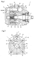
- Fig. 1 is a longitudinal sectional view of a vane pump.
- Fig. 2 is a view of a front housing in the state seen from the left side in Fig. 1.
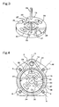
- Fig. 3 is a perspective view of a side plate.
- Fig. 4 is a view in the state where the side plate is placed within a front housing shown in Fig. 2.
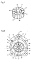
- Fig. 5 is a front view of a rear housing.
- Fig. 6 is a perspective view of a cam ring.
- Fig. 7 is a perspective view of a rotor.
- Fig. 8 is a view showing a state where the side plate, the cam ring and the rotor are placed within the front housing.
- Fig.9 is a front view of the rear housing when the installing angle of the side plate is changed.
- Fig.10 is a front view of the rear housing when the installing angle of the side plate is changed.
- As shown in Fig. 1, the
vane pump 1 comprises afront housing 2 and arear housing 4 mounted on oneface 3 of thefront housing 2. As shown in Fig. 2, therear housing 4 is mounted to thefront housing 2 by two pairs of mountingportions portions - The
front housing 2 has aspace 9. Thespace 9 is constructed so that oneface 3 side of thefront housing 2 is opened and the other face side is closed, and ashaft hole 10 is formed on the other face so that a rotatingshaft 11 is inserted into thespace 9 from theshaft hole 10. Also, as shown in Fig. 1, aninflow passage 12 is formed in thefront housing 2. The upstream end of thisinflow passage 12 is acommunication port 13 capable of being connected to an oil tank (not shown), while the downstream end is asuction port 14 and opened in the oneface 3 of thefront housing 2. - As shown in Fig. 1, in the
space 9, asideplate 15, acam ring 16 and arotor 17 are placed coaxially. A space between theside plate 15 and thefront housing 2 is apressure chamber 18. As shown in the same Fig. 1, a drain passage 19 (shown by a dotted line in Fig. 1) is formed inside the bottom face of thepressure chamber 18. Thedrain passage 19 is a passage for returning the working fluid internally leaking to the side of a seal member of the rotatingshaft 11 due to a clearance and the like at each portion to thecommunication passage 12 on the low pressure side. And in order to form thedrain passage 19, as shown in Fig. 2, the bottom face of thepressure chamber 18 is protruded so as to expand as a built-upportion 20 into thepressure chamber 18. Also, in thepressure chamber 18, adischarge hole 21 is formed at a position avoiding the built-upportion 20 so as to discharge the working fluid brought into a high pressure in thepressure chamber 18 through thedischarge hole 21. Moreover, as shown in Fig. 2, a line N connecting a pair of themounting portion 5 and themounting portion 6 opposed to each other having theshaft hole 10 interposed between them and a line M connecting a pair of themounting portion 7 and themounting portion 8 opposed to each other having theshaft hole 10 interposed between them are provided so as to form an angle of about 45 degrees with respect to a line L connecting theshaft hole 10 and thesuction port 14. These lines M and N are crossed with each other at right angles. - As shown in Fig. 3, the
side plate 15 is formed in a disk state. At the center of theside plate 15, acenter hole 22 through which the rotatingshaft 11 penetrates is formed. Also, in theside plate 15, afirst discharge port 23 as well as asecond discharge port 24 and afirst suction port 25 and asecond suction port 26 are provided. Here, as shown in Fig. 4, thefirst suction port 25 is a port located in the forward rotation direction (arrow direction in Fig. 4) of therotor 17 with reference to thesuction port 14 formed in thefront housing 2, and thesecond suction port 26 is a port located in the backward rotation direction of therotor 17 with reference to thesuction port 14. As shown in Fig. 4, thefirst discharge port 23 and thesecond discharge port 24 are provided at positions opposite to each other having thecenter hole 22 of theside plate 15 interposed between them, and thefirst suction port 25 and thesecond suction port 26 are provided at positions opposite to each other having thecenter hole 22 interposed between them. Thefirst discharge port 23 and thesecond discharge port 24 are located on the above-mentioned line M. Also, thefirst suction port 25 and thesecond suction port 26 are located on the above-mentioned line N. - Moreover, as shown in Figs. 3 and 4, in the
side plate 15, a plurality of back-pressure grooves 27 are formed coaxially with thecenter hole 22. These back-pressure grooves 27 communicate with the above pressure chamber 18 (shown in Fig. 1) In theside plate 15, two mountingpins pins center hole 22 interposed between them. Corresponding to the positions of these two mountingpins rear housing 4. By inserting tip ends of the mounting pins 29, 30 through the pin holes 31,32 of therear housing 4, theside plate 15 is positioned. - The
side plate 15 can be installed in the state where it is rotated by a desired angle within thespace 9 of thefront housing 2 as shown in Fig. 4. And in this case, according to the installed angle of theside plate 15, as shown in Fig. 5, the positions of the pin holes 31, 32 provided in therear housing 4 are determined. In this way, by determining the positions of the pin holes 31, 32 provided in therear housing 4 according to the installed angle of theside plate 15, theside plate 15 is positioned by therear housing 4 at the desired installed angle. - The
cam ring 16 is, as shown in Fig. 6, formed in the annular state, and the inner face is acam face 33 in an oval shape. In thecam ring 16, pin holes 34, 35 through which the mounting pins 29, 30 are inserted are formed. - The
rotor 17 is, as shown in Fig. 8, housed in thecam ring 16 and mounted on therotating shaft 11. In therotor 17, as shown in Fig. 7, a plurality ofvane housing grooves 36 are provided in the radial state and in each of thevane housing grooves 36, avane 37 is provided capable of going in/out. The base end side of thevane housing grooves 36 communicates with thepressure chamber 18 of thefront housing 2 through the back-pressure grooves 27 provided in theside plate 15 and urges thevanes 37 in the direction protruding from thevane housing grooves 36 by the pressure in thepressure chamber 18. - Therefore, as shown in Fig. 8, with rotation of the
rotor 17, the tip ends of thevanes 37 are brought into sliding contact with thecam face 33 of thecam ring 16, and a pump chamber P surrounded by the outer circumferential face of therotor 17 and thevanes 37 as well as thecam face 33 is formed. - The pump chamber P is varied with the rotation of the
rotor 17, the volume thereof repeating expansion and contraction. And in theside plate 15, thefirst suction port 25 and thesecond suction port 26 are provided at the positions matching the expansion process of the pump chamber P, while thefirst discharge port 23 and thesecond discharge port 24 are provided at the positions matching the contraction process. - As shown in Fig. 5, in the
rear housing 4, a suction passage is formed for sucking the working fluid through the suction port 14 (shown by a two-dotted chain line in Fig.5) of thefront housing 2. The suction passage is branched in the bifurcated state into a firstbranch suction passage 38 and a secondbranch suction passage 39. In the state where therear housing 4 is mounted to thefront housing 2, abranch portion 40 of the suction passage is opposed to thesuction port 14 of the front housing 2 (shown by the two-dotted chain line in Fig. 5), while aterminal portion 38a of the firstbranch suction passage 38 is opposed to thefirst suction port 25 of the side plate 15 (shown by a two-dotted chain line in Fig. 5) and aterminal portion 39a of the secondbranch suction passage 39 is opposed to thesecond suction port 26 of theside plate 15. Also, as shown in Fig. 5, in therear housing 4, a first discharge-port-correspondingrecess portion 41 is formed corresponding to thefirst discharge port 23 of the side plate 15 (shown by the two-dotted chain line in Fig. 5), a second discharge-port-correspondingrecess portion 42 is formed corresponding to thesecond discharge port 24, and moreover, a back-pressure groove correspondingrecess portion 43 is formed corresponding to the back-pressure groove 27 of theside plate 15. In Fig. 1,reference numeral 44 denotes a flow-rate regulating valve. The flow-rate regulating valve 44 is provided between thecommunication passage 12 and thepressure chamber 18 for controlling the flow rate discharged from thedischarge port 21, not shown, in the flow rate of the high-pressure working fluid discharged from thedischarge port 21 of thepressure chamber 18 and returning excess working fluid to theinflow passage 12. - Next, action will be described. As compared with the background arts, as shown in Fig. 4, with the
suction port 14 as reference, thefirst suction port 25 located in the forward rotation direction (arrow direction in Fig. 4) of therotor 17 is located close to thesuction port 14, while thesecond suction port 26 located in the backward rotation direction of therotor 17 is located far away from thesuction port 14. - As a result, as shown in Fig. 5, the first
branch suction passage 38 becomes shorter than the secondbranch suction passage 39, and the flow passage resistance of the firstbranch suction passage 38 is decreased as compared with that of the secondbranch suction passage 39. Thus, the suction efficiency from thefirst suction port 25 is improved, and the balance in suction efficiency between thefirst suction port 25 and thesecond suction port 26 can be made better. Also, since the suction efficiency on thefirst suction port 25 side is improved, a phenomenon that a negative pressure is generated particularly at high rotation in thefirst suction port 25 can be suppressed and as a result, generation of cavitations on thefirst suction port 25 side can be restricted and moreover, generation of vibration noise can be restrained. - Also, as compared with the background arts, as shown in Fig. 4, since the
first discharge port 23 is brought close to the mountingportion 7 and thesecond discharge port 24 to the mountingportion 8, in the vicinity of thefirst discharge port 23 and thesecond discharge port 24, therear housing 4 is maintained in the state firmly mounted to thefront housing 2. As a result, even if the high-pressure working fluid acts on thefirst discharge port 23 and thesecond discharge port 24, therear housing 4 is difficult to be separated from thefront housing 2, and a clearance is hardly generated between the both. As a result, the clearance between therear housing 4 and therotor 17 as well as thevane 37 is prevented from being widened and leakage of the working fluid from the pump chamber P to another pump chamber P through the clearance is prevented. Therefore, as compared with the background arts, there is a working effect that volume efficiency can be improved. - Also, as shown in Fig. 4, since the
first discharge port 23 is located avoiding the built-up portion 20 (shown by the two-dotted chain line in Fig. 4) of the drain passage 19 (shown in Fig. 1), the high-pressure working fluid can be discharged from thedischarge hole 21 efficiently. - Moreover, as shown in Fig. 5, since the pin holes 31, 32 provided in the
rear housing 4 can be formed at positions with a wide space avoiding the twobranch suction passages cam ring 16 through which the mounting pins 29, 30 are inserted can be kept small and vibration noise can be suppressed. - Fig. 5 shows the state where the
side plate 15 is rotated and installed so that a straight line connecting the shaft center of therotating shaft 11 to thefirst discharge port 23 and thesecond discharge port 24 forms 45 degrees with the reference line L connecting the shaft center of therotating shaft 11 and thesuction port 14, while Fig. 9 shows the state where theside plate 15 is rotated and installed so that a straight line X connecting the shaft center of therotating shaft 11 to thefirst discharge port 23 and thesecond discharge port 24 forms 22.5 degrees with the reference line L connecting the shaft center of therotating shaft 11 and thesuction port 14. - Also, Fig. 10 shows the state where the
side plate 15 is rotated and installed so that a straight line y connecting the shaft center of therotating shaft 11 to thefirst discharge port 23 and thesecond discharge port 24forms 30 degrees with the reference line L connecting the shaft center of therotating shaft 11 and thesuction port 14. - It is needless to say that a balance of the suction efficiency between the
first suction port 25 and thesecond suction port 26 can be improved in the embodiment shown in Figs. 9 and 10. Also, as compared with the background arts, since thefirst discharge port 23 is brought closer to the mountingportion 5 and thesecond discharge port 24 to the mountingportion 6, even if the high-pressure working fluid acts on thefirst discharge port 23 and thesecond discharge port 24, therear housing 4 is hard to be separated from thefront housing 2, and a clearance is hardly generated between the both. Therefore, since a clearance between therear housing 4 and therotor 7 as well as thevanes 37 is prevented from being widened and as a result, leakage of the working fluid from the pump chamber P to another pump chamber P through the clearance is prevented, and such a working effect that the volume efficiency can be improved as compared with the background arts can be obtained. - In the above description, an example was described that the
pressure chamber 18 is provided on thefront housing 2 side, but the present invention can be applied to the case that thepressure chamber 18 is provided on therear housing 4 side. Also, the present invention can be applied even if thedischarge ports suction ports side plate 15 or therear housing 4. - Also, in the above description, an example was described that the mounting pins 29,30 are set up on the
side plate 15, but the present invention can be also applied to the case that the mounting pins 29, 30 are installed upright on therear housing 4, while pin holes are provided in thecam ring 16 and theside plate 15 so that therear housing 4 and theside plate 15 are positioned by inserting the mounting pins 29, 30 into the pin holes.
Claims (3)
- A vane pump in which a rotor with vanes and a side plate are arranged in a space formed by a front housing and a rear housing mounted to the front housing by a mounting portion,
two suction ports and discharge ports are provided at positions opposite to each other with a predetermined angle around a rotating shaft of said rotor separated at least in one of said side plate or the rear housing, and
a working fluid sucked in through a suction port provided in said front housing is sucked into a pump chamber from said suction port, a pumping action is given to the working fluid by rotation of said rotor and then, the working fluid is discharged from said discharge port,
wherein by positioning said side plate or the rear housing in the state where said discharge port is brought close to said mounting portion, the position of the first suction port located in the forward rotation direction of the rotor is brought closer to the suction port than the position of the second suction port located in the backward rotation direction of the rotor with said suction port as reference. - The vane pump as described in Claim 1, wherein the mounting portions are provided at positions opposed to each other with said rotating shaft as the center and two discharge ports are provided on a line connecting the two mounting portions.
- The vane pump as described in Claim 1 or 2, wherein a space between said side plate and the front housing is a pressure chamber, a drain passage is provided for returning the working fluid internally leaking inside the bottom surface of the pressure chamber to the suction port side, and said discharge port is provided avoiding the position of the drain passage.
Applications Claiming Priority (1)
| Application Number | Priority Date | Filing Date | Title |
|---|---|---|---|
| JP2005358941A JP2007162554A (en) | 2005-12-13 | 2005-12-13 | Vane pump |
Publications (2)
| Publication Number | Publication Date |
|---|---|
| EP1818502A2 true EP1818502A2 (en) | 2007-08-15 |
| EP1818502A3 EP1818502A3 (en) | 2014-06-11 |
Family
ID=37834111
Family Applications (1)
| Application Number | Title | Priority Date | Filing Date |
|---|---|---|---|
| EP06380320.9A Withdrawn EP1818502A3 (en) | 2005-12-13 | 2006-12-12 | Vane pump |
Country Status (4)
| Country | Link |
|---|---|
| US (2) | US20070134120A1 (en) |
| EP (1) | EP1818502A3 (en) |
| JP (1) | JP2007162554A (en) |
| CN (1) | CN1982716A (en) |
Families Citing this family (14)
| Publication number | Priority date | Publication date | Assignee | Title |
|---|---|---|---|---|
| US8348645B2 (en) * | 2009-08-11 | 2013-01-08 | Woodward, Inc. | Balanced pressure, variable displacement, dual lobe, single ring, vane pump |
| DE102010051192B4 (en) * | 2010-11-15 | 2012-12-06 | Sew-Eurodrive Gmbh & Co. Kg | Conveying device, drive and manufacturing method for a conveyor |
| WO2013176143A1 (en) * | 2012-05-21 | 2013-11-28 | ナブテスコオートモーティブ株式会社 | Vacuum pump |
| JP6111093B2 (en) * | 2013-03-06 | 2017-04-05 | Kyb株式会社 | Vane pump |
| KR102060468B1 (en) * | 2013-03-08 | 2019-12-30 | 엘지전자 주식회사 | Vane pump |
| CN104074741B (en) * | 2013-03-26 | 2017-09-29 | 德昌电机(深圳)有限公司 | Fluid pump |
| JP6210870B2 (en) | 2013-12-18 | 2017-10-11 | 株式会社ショーワ | Vane pump |
| JP6411228B2 (en) * | 2015-01-19 | 2018-10-24 | アイシン・エィ・ダブリュ株式会社 | Transmission device |
| JP6454247B2 (en) * | 2015-09-11 | 2019-01-16 | Kyb株式会社 | Vane pump |
| CN105156320B (en) * | 2015-10-19 | 2018-07-06 | 蔡伟 | Plug-in vane pump and its integrated package |
| JP6220837B2 (en) * | 2015-11-02 | 2017-10-25 | Kyb株式会社 | Vane pump |
| JP6639905B2 (en) * | 2015-12-25 | 2020-02-05 | 株式会社ショーワ | Vane pump device |
| US11603837B2 (en) * | 2018-03-08 | 2023-03-14 | Cameron James Pittendrigh | Rotary fluid device |
| DE102020105173A1 (en) * | 2020-02-27 | 2021-09-02 | Fte Automotive Gmbh | Pump unit for a drive train of a motor vehicle |
Family Cites Families (17)
| Publication number | Priority date | Publication date | Assignee | Title |
|---|---|---|---|---|
| US2642802A (en) * | 1948-12-14 | 1953-06-23 | Vickers Inc | Dual rotary pump for power transmissions |
| US3481276A (en) * | 1967-11-27 | 1969-12-02 | Abex Corp | Vane tracking in hydraulic pumps |
| US3790314A (en) * | 1972-05-22 | 1974-02-05 | Abex Corp | Vane pump having extended undervane suction ports |
| JPS6126638Y2 (en) * | 1980-12-27 | 1986-08-09 | ||
| JP2670770B2 (en) * | 1986-05-20 | 1997-10-29 | 株式会社ユニシアジェックス | Vane pump |
| JPH0197084A (en) * | 1987-10-09 | 1989-04-14 | Hitachi Ltd | Multiplex transmission system and signal generator therefor |
| DE69000353T2 (en) * | 1989-05-24 | 1993-05-06 | Vickers Inc | WINGED CELL MACHINE. |
| JP2963519B2 (en) * | 1990-10-11 | 1999-10-18 | 豊田工機株式会社 | Vane pump |
| US5380178A (en) * | 1994-02-10 | 1995-01-10 | Trw Inc. | Rotary device and method of assembly |
| JPH0874750A (en) * | 1994-08-31 | 1996-03-19 | Unisia Jecs Corp | Vane pump |
| JP3547242B2 (en) * | 1995-11-17 | 2004-07-28 | カヤバ工業株式会社 | Vane pump |
| JP3710227B2 (en) * | 1995-12-06 | 2005-10-26 | カヤバ工業株式会社 | Vane pump |
| DE10027813A1 (en) * | 2000-06-05 | 2001-12-13 | Luk Fahrzeug Hydraulik | Cellular pump housing cover over pump unit is fixed to housing at points spaced over straight line spanning pressure field with second fixers at other two cover corners for pressure symmetry. |
| JP2002130151A (en) * | 2000-10-30 | 2002-05-09 | Unisia Jecs Corp | Vane pump |
| JP3744349B2 (en) * | 2000-11-27 | 2006-02-08 | 豊田工機株式会社 | Pump device |
| DE10233582B4 (en) * | 2002-07-24 | 2011-03-24 | Zf Lenksysteme Gmbh | Vane pump for delivering a fluid |
| JP2004084565A (en) * | 2002-08-27 | 2004-03-18 | Kayaba Ind Co Ltd | Vane pump |
-
2005
- 2005-12-13 JP JP2005358941A patent/JP2007162554A/en active Pending
-
2006
- 2006-12-11 CN CN200610162061.3A patent/CN1982716A/en active Pending
- 2006-12-12 US US11/609,338 patent/US20070134120A1/en not_active Abandoned
- 2006-12-12 EP EP06380320.9A patent/EP1818502A3/en not_active Withdrawn
-
2009
- 2009-02-24 US US12/391,267 patent/US7841846B2/en not_active Expired - Fee Related
Also Published As
| Publication number | Publication date |
|---|---|
| JP2007162554A (en) | 2007-06-28 |
| US20070134120A1 (en) | 2007-06-14 |
| CN1982716A (en) | 2007-06-20 |
| EP1818502A3 (en) | 2014-06-11 |
| US20090162230A1 (en) | 2009-06-25 |
| US7841846B2 (en) | 2010-11-30 |
Similar Documents
| Publication | Publication Date | Title |
|---|---|---|
| US7841846B2 (en) | Vane pump with improved internal port placement | |
| US8419392B2 (en) | Variable displacement vane pump | |
| JP5022139B2 (en) | Variable displacement vane pump | |
| JP3041305B2 (en) | Scroll compressor and method of forming the same | |
| JP6182821B2 (en) | Variable displacement vane pump | |
| CN105074216B (en) | Variable capacity vane pump | |
| CN108350878A (en) | Vane pump | |
| CN105190038A (en) | vane pump | |
| US8690557B2 (en) | Variable displacement vane pump | |
| CN115263756B (en) | A high efficiency liquid ring vacuum pump | |
| CN107002672A (en) | Variable displacement vane pump | |
| KR101226388B1 (en) | Pump with selectable outlet pressure | |
| CN105190039B (en) | Variable Capacity Vane Pump | |
| JP6948195B2 (en) | Pump device | |
| US6599111B2 (en) | Vane pump having an intake groove through a side wall member | |
| JP5204739B2 (en) | Vane pump | |
| CN108496007A (en) | Vane pump | |
| JP4530875B2 (en) | Vane pump | |
| JP5443427B2 (en) | Variable displacement vane pump | |
| JP3942992B2 (en) | Vane pump | |
| JP4410528B2 (en) | Variable displacement vane pump | |
| JP2006177230A (en) | Pump device | |
| CN112664447B (en) | Positive displacement pump and method for operating a positive displacement pump | |
| JP2009052525A (en) | Vane pump | |
| JP2525723Y2 (en) | Vane pump |
Legal Events
| Date | Code | Title | Description |
|---|---|---|---|
| PUAI | Public reference made under article 153(3) epc to a published international application that has entered the european phase |
Free format text: ORIGINAL CODE: 0009012 |
|
| AK | Designated contracting states |
Kind code of ref document: A2 Designated state(s): AT BE BG CH CY CZ DE DK EE ES FI FR GB GR HU IE IS IT LI LT LU LV MC NL PL PT RO SE SI SK TR |
|
| AX | Request for extension of the european patent |
Extension state: AL BA HR MK YU |
|
| PUAL | Search report despatched |
Free format text: ORIGINAL CODE: 0009013 |
|
| AK | Designated contracting states |
Kind code of ref document: A3 Designated state(s): AT BE BG CH CY CZ DE DK EE ES FI FR GB GR HU IE IS IT LI LT LU LV MC NL PL PT RO SE SI SK TR |
|
| AX | Request for extension of the european patent |
Extension state: AL BA HR MK RS |
|
| RIC1 | Information provided on ipc code assigned before grant |
Ipc: F04C 14/14 20060101ALI20140506BHEP Ipc: F04C 15/06 20060101ALI20140506BHEP Ipc: F04C 2/344 20060101ALI20140506BHEP Ipc: F01C 21/10 20060101AFI20140506BHEP |
|
| STAA | Information on the status of an ep patent application or granted ep patent |
Free format text: STATUS: THE APPLICATION IS DEEMED TO BE WITHDRAWN |
|
| 18D | Application deemed to be withdrawn |
Effective date: 20140701 |