EP1818487A2 - Flexible dual-axis circuit board and hinge - Google Patents
Flexible dual-axis circuit board and hinge Download PDFInfo
- Publication number
- EP1818487A2 EP1818487A2 EP06124237A EP06124237A EP1818487A2 EP 1818487 A2 EP1818487 A2 EP 1818487A2 EP 06124237 A EP06124237 A EP 06124237A EP 06124237 A EP06124237 A EP 06124237A EP 1818487 A2 EP1818487 A2 EP 1818487A2
- Authority
- EP
- European Patent Office
- Prior art keywords
- circuit board
- dual
- axis
- hinge
- loop
- Prior art date
- Legal status (The legal status is an assumption and is not a legal conclusion. Google has not performed a legal analysis and makes no representation as to the accuracy of the status listed.)
- Granted
Links
- 230000007704 transition Effects 0.000 claims description 19
- 230000001413 cellular effect Effects 0.000 description 3
- 230000005540 biological transmission Effects 0.000 description 2
- 238000007373 indentation Methods 0.000 description 2
- 238000012423 maintenance Methods 0.000 description 2
- 230000004048 modification Effects 0.000 description 2
- 238000012986 modification Methods 0.000 description 2
- 230000006872 improvement Effects 0.000 description 1
- 230000007257 malfunction Effects 0.000 description 1
- 230000004899 motility Effects 0.000 description 1
- 230000036544 posture Effects 0.000 description 1
- 230000008439 repair process Effects 0.000 description 1
- 230000008054 signal transmission Effects 0.000 description 1
- 230000000007 visual effect Effects 0.000 description 1
Images



Classifications
-
- E—FIXED CONSTRUCTIONS
- E05—LOCKS; KEYS; WINDOW OR DOOR FITTINGS; SAFES
- E05D—HINGES OR SUSPENSION DEVICES FOR DOORS, WINDOWS OR WINGS
- E05D11/00—Additional features or accessories of hinges
- E05D11/0081—Additional features or accessories of hinges for transmitting energy, e.g. electrical cable routing
-
- E—FIXED CONSTRUCTIONS
- E05—LOCKS; KEYS; WINDOW OR DOOR FITTINGS; SAFES
- E05D—HINGES OR SUSPENSION DEVICES FOR DOORS, WINDOWS OR WINGS
- E05D3/00—Hinges with pins
- E05D3/06—Hinges with pins with two or more pins
- E05D3/10—Hinges with pins with two or more pins with non-parallel pins
-
- H—ELECTRICITY
- H04—ELECTRIC COMMUNICATION TECHNIQUE
- H04M—TELEPHONIC COMMUNICATION
- H04M1/00—Substation equipment, e.g. for use by subscribers
- H04M1/02—Constructional features of telephone sets
- H04M1/0202—Portable telephone sets, e.g. cordless phones, mobile phones or bar type handsets
- H04M1/0206—Portable telephones comprising a plurality of mechanically joined movable body parts, e.g. hinged housings
- H04M1/0208—Portable telephones comprising a plurality of mechanically joined movable body parts, e.g. hinged housings characterized by the relative motions of the body parts
- H04M1/021—Portable telephones comprising a plurality of mechanically joined movable body parts, e.g. hinged housings characterized by the relative motions of the body parts using combined folding and rotation motions
- H04M1/0212—Portable telephones comprising a plurality of mechanically joined movable body parts, e.g. hinged housings characterized by the relative motions of the body parts using combined folding and rotation motions with a two degrees of freedom mechanism, i.e. folding around a first axis and rotating around a second axis perpendicular to the first
-
- H—ELECTRICITY
- H05—ELECTRIC TECHNIQUES NOT OTHERWISE PROVIDED FOR
- H05K—PRINTED CIRCUITS; CASINGS OR CONSTRUCTIONAL DETAILS OF ELECTRIC APPARATUS; MANUFACTURE OF ASSEMBLAGES OF ELECTRICAL COMPONENTS
- H05K1/00—Printed circuits
- H05K1/02—Details
- H05K1/0277—Bendability or stretchability details
- H05K1/028—Bending or folding regions of flexible printed circuits
Definitions
- the present invention relates generally to a dual-axis circuit board, and more particularly to a flexible dual-axis circuit board with multidirectional motility.
- the device comprises three main parts: an upper cover, a body, and a hinge.
- this kind of foldable structure can be opened and closed in only one direction, which limits practical use.
- the screen in order to match the cover and body, must be shaped like a rectangle and oriented in only one direction, which is not convenient for users to read documents and websites that are oriented otherwise.
- the new designs can accommodate different operating modes.
- the upper cover can open and close along two orthogonal directions selectively, making the screen disposed in either portrait or landscape mode to fit the visual demand.
- electronic signal transmission necessitates a dual-axis circuit board.
- the dual-axis circuit board could be a dual-axis cable, too.
- a kind of known flexible circuit board could be assembled with a two-dimensional dual-axis hinge.
- the flexible circuit board extended from the upper cover or the body of the foldable device and its end, circles one side of the hinge and then connects with the circuit board in the body or the upper cover of the foldable device.
- the present invention provides a multidirectional and flexible dual-axis circuit board.
- the upper cover and the body of the foldable device are foldable in two directions.
- the dual-axis circuit board circles the hinge with sufficient length, it can absorb the stress produced by frequent folding and unfolding. The probability of damage or breakage can be lowered significantly, thereby increasing the operating reliability of personal electronic products.
- the dual-axis circuit board uses a perpendicular connecting section circuit board to connect an upper circuit board and a lower circuit board respectively.
- the dual-axis circuit board is assembled into a three-dimensional dual-axis hinge, two ends of the dual-axis circuit board respectively circle around the two hinges of the three-dimensional dual-axis hinge, thus forming two orthogonal circular rings.
- the ends of two circular loops connect the circuit boards in the upper cover with the body of the foldable device.
- a flexible dual-axis circuit board 200 includes a connecting section circuit board 210, an upper circuit board 220, a lower circuit board 230, and the flexible dual-axis circuit board 200.
- the connecting section circuit board 210 can be several partitioned sections and is shaped somewhat like the character "C.” It includes a raised section 211, an upper transition section 212 and a lower transition section 213 that extends from two ends of the raised section 211.
- An included angle ⁇ of the raised section 211 is preferably 45 degrees from horizontal.
- An upper loop 218 is disposed between the upper circuit board 220 and the upper transition section 212; and a lower loop 219 is disposed between the lower circuit board 230 and lower transition section 213. Therefore, the upper circuit board 220 and the lower circuit board 230 are preferably disposed orthogonally.
- the board When the flexible dual-axis circuit board 200 is assembled within the hinge of an electronic device, the board cannot be slanted or slid and cannot interfere with the functions of the flexible dual-axis circuit board 200.
- Figure 2 illustrates an isometric view of the wound flexible dual-axis circuit board 200.
- the flexible dual-axis circuit board 200 comprises at least one connecting section circuit board 210, a first circuit board (like the upper circuit board 220) and a second circuit board (like the lower circuit board 230).
- the connecting section circuit board 210 comprises the raised section 211, the upper transition section 212 and the lower transition section 213.
- the included angles between the raised section 211 and the upper transition section 212 and between the raised section 211 and lower transition section 213 are all preferably 90 degrees.
- the connecting section circuit board 210 further includes a first circular loop (like the upper loop 218) and a second circular loop (like the lower loop 219). The first circular loop connects the first circuit board; the second circular loop connects the second circuit board.
- the upper circuit board 220 connects behind the upper loop 218 and extends in a first extending direction 222 toward the inside of the flexible dual-axis circuit board 200.
- the lower circuit board 230 connects behind the lower loop 219 and extends in a second extending direction 232 toward the inside of the flexible dual-axis circuit board 200, too.
- the upper circuit board 220 couples with the upper loop 221, and the lower circuit board 230 couples with the lower loop 231, making the upper circuit board 220 and the lower circuit board 230 disposed in two parallel planes; and the upper loop 221 and the lower loop 231 are preset at a certain angle, preferably 90 degrees.
- the raised section 211 which has a certain length, can make the upper loop 221 and the circular loop 231 form a difference in height.
- FIG. 3 illustrates an exploded isometric view of a flexible dual-axis circuit board 200 assembled into a dual-axis hinge 300.
- the flexible dual-axis circuit board 200 is located between an upper component 310 and a lower component 320.
- an upper axis sleeve 311 and lower axis sleeve 321 are connected to two formative hinges by a protrusion 312 and a protrusion 322 respectively.
- the upper component 310 and the lower component 320 can be fashioned as concave slots. After the upper component 310 and the lower component 320 are assembled, they can form a circuit cavity and a circuit outlet for passing through the flexible dual-axis circuit board 200.
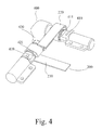
- the dual-axis hinge 400 comprises an upper hinge 410, a lower hinge 420 and a perpendicular connecting section 430.
- the perpendicular connecting section 430 can make the upper hinge 410 and the lower hinge 420 disposed in two parallel planes, and these two hinges have a 90-degree included angle.
- the raised section 211, the upper transition section 212 and the lower transition section 213 all pass through the perpendicular connecting section 430.
- the upper circuit board 220 circles at least once on an upper concave loop 411 of the upper hinge 410; the lower circuit board 230 also circles at least once on a lower loop 421 of the upper hinge 420.
- the flexible dual-axis circuit board 200 and the dual-axis hinge 400 are assembled into a foldable device (like a cellular phone), wherein the foldable device can be folded along two orthogonal directions.
- the upper circuit board 220 circles around the upper hinge 410 and is assembled into an upper cover 500 of the foldable device
- the upper cover 500 can open along the direction perpendicular to the upper hinge 410 to operate like a cellular phone
- the lower circuit board 230 circles around the lower hinge 420 and is assembled into a body 600 of the foldable device.
- the body 600 can open along the direction perpendicular to the lower hinge 420 to operate like a laptop.
- the upper hinge 410 of the dual-axis hinge 400 can be contained within the upper cover 500 of the foldable device and the lower hinge 420 can be contained within the body 600 of the foldable device, the upper cover 500 and the body 600 of the foldable device do not need the raised parts and indentations of traditional structures, which are unattractive and exposed.
- the present invention has many advantages over the prior art, such as the following:
Landscapes
- Engineering & Computer Science (AREA)
- Mechanical Engineering (AREA)
- Microelectronics & Electronic Packaging (AREA)
- Signal Processing (AREA)
- Combinations Of Printed Boards (AREA)
- Telephone Set Structure (AREA)
- Calculators And Similar Devices (AREA)
Abstract
Description
- The present invention relates generally to a dual-axis circuit board, and more particularly to a flexible dual-axis circuit board with multidirectional motility.
- People use numerous kinds of portable electronic devices in their daily lives, such as pagers, cellular phones, personal digital assistants (PDAs), and pocket PCs. People find these devices so convenient that manufacturers make every endeavor to design more user-friendly products in order to meet consumer demand.
- One major improvement was the design of a foldable device. This design has two advantages. First, it increases the amount of information that can be displayed at a time because the size of the screen can be increased. Second, the operation interface can contain more functions because the size of the interface can be increased. The device comprises three main parts: an upper cover, a body, and a hinge. In general, this kind of foldable structure can be opened and closed in only one direction, which limits practical use. Furthermore, the screen, in order to match the cover and body, must be shaped like a rectangle and oriented in only one direction, which is not convenient for users to read documents and websites that are oriented otherwise.
- The new designs can accommodate different operating modes. The upper cover can open and close along two orthogonal directions selectively, making the screen disposed in either portrait or landscape mode to fit the visual demand. In this kind of foldable device, electronic signal transmission necessitates a dual-axis circuit board. The dual-axis circuit board could be a dual-axis cable, too.
- A kind of known flexible circuit board could be assembled with a two-dimensional dual-axis hinge. The flexible circuit board, extended from the upper cover or the body of the foldable device and its end, circles one side of the hinge and then connects with the circuit board in the body or the upper cover of the foldable device.
- However the known structure has some disadvantages:
- 1. This kind of two-dimensional dual-axis hinge must be applied in a foldable device that has a raised base or an indentation. This application degrades the appearance and value of electronic products, making them look cheap, and also affects the convenience of input as it interferes with handling postures.
- 2. The manner in which the flexible circuit board circles the hinge reduces the durability of the flexible circuit board. After frequent operation, the transmitting components of the flexible circuit board become fragile.
- 3. This kind of flexible circuit board is an extension of the circuit board of the upper cover or the body. If the flexible circuit board is damaged, the time and material costs of repairing are very high.
- It is therefore an aspect of the present invention to provide a multidirectional and flexible dual-axis circuit board. When it applies to a portable electronic product, the upper cover and the body of the foldable device are foldable in two directions. Furthermore, because the dual-axis circuit board circles the hinge with sufficient length, it can absorb the stress produced by frequent folding and unfolding. The probability of damage or breakage can be lowered significantly, thereby increasing the operating reliability of personal electronic products.
- It is another aspect of the present invention to provide a flexible dual-axis circuit board that is assembled into a dual-axis hinge as an independent part. The repair time and material costs of maintenance can thereby be reduced significantly.
- It is still another aspect of the present invention to provide a flexible dual-axis circuit board hidden inside the dual-axis hinge to connect with the transmission circuit of the upper cover and the body of the portable electronic product so as to avoid exposing the vulnerable circuit board, thereby reducing malfunction resulting from external forces.
- According to the aforementioned aspects of the present invention, a new dual-axis circuit board is provided. In one embodiment of the present invention, the dual-axis circuit board uses a perpendicular connecting section circuit board to connect an upper circuit board and a lower circuit board respectively. When the dual-axis circuit board is assembled into a three-dimensional dual-axis hinge, two ends of the dual-axis circuit board respectively circle around the two hinges of the three-dimensional dual-axis hinge, thus forming two orthogonal circular rings. The ends of two circular loops connect the circuit boards in the upper cover with the body of the foldable device.
- It is to be understood that both the foregoing general description and the following detailed description are by examples and are intended to provide further explanation of the invention as claimed.
- The accompanying drawings are included to provide a further understanding of the invention and are incorporated in and constitute a part of this specification. The drawings illustrate embodiments of the invention and, together with the description, serve to explain the principles of the invention. In the drawings,
- Fig. 1 shows a schematic plan view of a dual-axis circuit board of the preferred embodiment of the present invention;
- Fig. 2 shows an isometric view of a dual-axis circuit board of the preferred embodiment of the present invention;
- Fig. 3 shows an exploded isometric view of a dual-axis circuit board assembled into a dual-axis hinge of the preferred embodiment of the present invention;
- Fig. 4 shows an isometric view of a dual-axis circuit board assembled into a dual-axis hinge of the preferred embodiment of the present invention;
- Fig. 5 shows an isometric view of a dual-axis circuit board assembled into a foldable device of the preferred embodiment of the present invention;
- Reference will now be made in detail to the present preferred embodiments of the invention, examples of which are illustrated in the accompanying drawings. Wherever possible, the same reference numbers are used in the drawings and the description to refer to the same or like parts.
- While the specification concludes with claims defining the features of the invention that are regarded as novel, it is believed that the invention will be better understood from a consideration of the following description in conjunction with the figures, in which like reference numerals are carried forward.
- Reference is made to Figure 1, which illustrates a flexible dual-axis circuit board of the preferred embodiment of the present invention. A flexible dual-
axis circuit board 200 includes a connectingsection circuit board 210, anupper circuit board 220, alower circuit board 230, and the flexible dual-axis circuit board 200. - The connecting
section circuit board 210 can be several partitioned sections and is shaped somewhat like the character "C." It includes a raisedsection 211, anupper transition section 212 and alower transition section 213 that extends from two ends of theraised section 211. An included angle θ of the raisedsection 211 is preferably 45 degrees from horizontal. Anupper loop 218 is disposed between theupper circuit board 220 and theupper transition section 212; and alower loop 219 is disposed between thelower circuit board 230 andlower transition section 213. Therefore, theupper circuit board 220 and thelower circuit board 230 are preferably disposed orthogonally. - When the flexible dual-
axis circuit board 200 is assembled within the hinge of an electronic device, the board cannot be slanted or slid and cannot interfere with the functions of the flexible dual-axis circuit board 200. Hence, there are four preset folding marks (or dents), such as a linkage of the raisedsection 211 and theupper transition section 212 as a firstupper folding mark 214, a linkage of theupper transition section 212 and theupper loop 218 as a secondupper folding mark 215, a linkage of the raisedsection 211 and thelower transition section 213 as a firstlower folding mark 216, and a linkage of thelower transition section 213 and thelower loop 219 as a secondlower folding mark 217. - Figure 2 illustrates an isometric view of the wound flexible dual-
axis circuit board 200. In a preferred embodiment of the present invention, the flexible dual-axis circuit board 200 comprises at least one connectingsection circuit board 210, a first circuit board (like the upper circuit board 220) and a second circuit board (like the lower circuit board 230). The connectingsection circuit board 210 comprises the raisedsection 211, theupper transition section 212 and thelower transition section 213. The included angles between the raisedsection 211 and theupper transition section 212 and between the raisedsection 211 andlower transition section 213 are all preferably 90 degrees. Moreover, the connectingsection circuit board 210 further includes a first circular loop (like the upper loop 218) and a second circular loop (like the lower loop 219). The first circular loop connects the first circuit board; the second circular loop connects the second circuit board. - The
upper circuit board 220 connects behind theupper loop 218 and extends in a first extendingdirection 222 toward the inside of the flexible dual-axis circuit board 200. Thelower circuit board 230 connects behind thelower loop 219 and extends in a second extendingdirection 232 toward the inside of the flexible dual-axis circuit board 200, too. - The
upper circuit board 220 couples with the upper loop 221, and thelower circuit board 230 couples with the lower loop 231, making theupper circuit board 220 and thelower circuit board 230 disposed in two parallel planes; and the upper loop 221 and the lower loop 231 are preset at a certain angle, preferably 90 degrees. The raisedsection 211, which has a certain length, can make the upper loop 221 and the circular loop 231 form a difference in height. - Reference is made to Figure 3 as well, which illustrates an exploded isometric view of a flexible dual-
axis circuit board 200 assembled into a dual-axis hinge 300. The flexible dual-axis circuit board 200 is located between anupper component 310 and alower component 320. After assembly of the above three components, anupper axis sleeve 311 andlower axis sleeve 321 are connected to two formative hinges by aprotrusion 312 and aprotrusion 322 respectively. - At the linkage of the
upper component 310 and thelower component 320, theupper component 310 and thelower component 320 can be fashioned as concave slots. After theupper component 310 and thelower component 320 are assembled, they can form a circuit cavity and a circuit outlet for passing through the flexible dual-axis circuit board 200. - Reference is also made to Figure 4, illustrating a three-dimensional dual-axis hinge module, which assembles the flexible dual-
axis circuit board 200 within a dual-axis hinge 400. The dual-axis hinge 400 comprises anupper hinge 410, alower hinge 420 and a perpendicular connectingsection 430. The perpendicular connectingsection 430 can make theupper hinge 410 and thelower hinge 420 disposed in two parallel planes, and these two hinges have a 90-degree included angle. The raisedsection 211, theupper transition section 212 and thelower transition section 213 all pass through the perpendicular connectingsection 430. Theupper circuit board 220 circles at least once on an upperconcave loop 411 of theupper hinge 410; thelower circuit board 230 also circles at least once on alower loop 421 of theupper hinge 420. - Referring to Figure 5, the flexible dual-
axis circuit board 200 and the dual-axis hinge 400 are assembled into a foldable device (like a cellular phone), wherein the foldable device can be folded along two orthogonal directions. For example, when theupper circuit board 220 circles around theupper hinge 410 and is assembled into anupper cover 500 of the foldable device, theupper cover 500 can open along the direction perpendicular to theupper hinge 410 to operate like a cellular phone; and thelower circuit board 230 circles around thelower hinge 420 and is assembled into abody 600 of the foldable device. Thebody 600 can open along the direction perpendicular to thelower hinge 420 to operate like a laptop. Because theupper hinge 410 of the dual-axis hinge 400 can be contained within theupper cover 500 of the foldable device and thelower hinge 420 can be contained within thebody 600 of the foldable device, theupper cover 500 and thebody 600 of the foldable device do not need the raised parts and indentations of traditional structures, which are unattractive and exposed. - According to the composition and the embodiments above, the present invention has many advantages over the prior art, such as the following:
- 1. The dual-axis circuit board circles the hinge so that the motive space of the hinge is resilient; therefore, the stress produced by frequent operation can be absorbed effectively. The likelihood that the electric transmission components of the circuit board become damaged is greatly reduced and allows an electronic product greater durability.
- 2. The dual-axis circuit board is independent from the circuit board that extends from the upper cover or the body. If the dual-axis circuit board is damaged, its material, maintenance and time costs are lower. The independent design also improves an electronic product's mass producibility.
- 3. The dual-axis circuit board allows for changing its transition angles or the number of its circles in order to accommodate different hinge structure needs.
- It will be apparent to those skilled in the art that various modifications and variations can be made to the structure of the present invention without departing from the scope or spirit of the invention. In view of the foregoing, it is intended that the present invention cover modifications and variations of this invention provided they fall within the scope of the following claims and their equivalents.
Claims (10)
- A dual-axis circuit board, comprising:at least one connecting circuit board comprising an upper transition section that connects with a lower transition section;an upper circuit board connecting to an upper transition section; anda lower circuit board connecting to the lower transition section, wherein the extended directions of the upper circuit board and the lower circuit board are not parallel.
- A dual-axis circuit board that comprises:at least one upper loop disposed to a first extended direction;an upper circuit board connecting with the extended direction of the upper loop;at least one lower loop disposed to a second extended direction; anda lower circuit board connecting with the extended direction of the lower loop, wherein the first extended direction and the second extended direction are not parallel.
- The dual-axis circuit board of claim 2, wherein the first extended direction and the second extended direction are approximately orthogonal.
- The dual-axis circuit board of claim 2, wherein the dual-axis circuit board further comprises a connecting circuit board disposed between the upper loop and the lower loop.
- The dual-axis circuit board of claim 2, wherein the dual-axis circuit board further comprises a raised section and two ends of the raised section connect with the upper loop and the lower loop, respectively.
- The dual-axis circuit board of claim 5, wherein the raised section slants approximately 45 degrees.
- The dual-axis circuit board of claim 2, wherein the extended directions of the upper circuit board and the lower circuit board are approximately orthogonal.
- A three-dimensional dual-axis hinge module for assembling into a foldable device, comprising:a dual-axis hinge comprising a perpendicular connecting section, an upper hinge and a lower hinge; anda dual-axis circuit board comprising a connecting section circuit board, an upper circuit board and a lower circuit board, which can be assembled with the dual-axis hinge.
- The three-dimensional dual-axis hinge module for assembling into a foldable device of claim 8, wherein the upper hinge and the lower hinge extend from the perpendicular connecting section and are disposed at approximately 90 degrees to each other.
- The three-dimensional dual-axis hinge module for assembling into a foldable device of claim 8, wherein the foldable device can be folded in two orthogonal directions.
Applications Claiming Priority (1)
| Application Number | Priority Date | Filing Date | Title |
|---|---|---|---|
| CN200610007435A CN100589677C (en) | 2006-02-10 | 2006-02-10 | Double-shaft circuit board |
Publications (3)
| Publication Number | Publication Date |
|---|---|
| EP1818487A2 true EP1818487A2 (en) | 2007-08-15 |
| EP1818487A3 EP1818487A3 (en) | 2008-12-31 |
| EP1818487B1 EP1818487B1 (en) | 2015-03-25 |
Family
ID=38042847
Family Applications (1)
| Application Number | Title | Priority Date | Filing Date |
|---|---|---|---|
| EP20060124237 Ceased EP1818487B1 (en) | 2006-02-10 | 2006-11-16 | Flexible dual-axis circuit board and hinge |
Country Status (2)
| Country | Link |
|---|---|
| EP (1) | EP1818487B1 (en) |
| CN (1) | CN100589677C (en) |
Cited By (1)
| Publication number | Priority date | Publication date | Assignee | Title |
|---|---|---|---|---|
| CN110337181A (en) * | 2019-08-14 | 2019-10-15 | 万诺电子(苏州)有限公司 | A kind of circuit board production process and its production equipment |
Families Citing this family (1)
| Publication number | Priority date | Publication date | Assignee | Title |
|---|---|---|---|---|
| CN111093316B (en) * | 2018-10-24 | 2021-08-24 | 鹏鼎控股(深圳)股份有限公司 | Circuit board and manufacturing method thereof |
Family Cites Families (3)
| Publication number | Priority date | Publication date | Assignee | Title |
|---|---|---|---|---|
| JP2002368440A (en) * | 2001-06-06 | 2002-12-20 | Toshiba Corp | Foldable electronic devices and their flexible substrates |
| JP3719221B2 (en) * | 2002-02-25 | 2005-11-24 | オムロン株式会社 | Rotating structure for signal relay |
| JP4187607B2 (en) * | 2003-08-14 | 2008-11-26 | 富士通株式会社 | Mobile wireless communication device |
-
2006
- 2006-02-10 CN CN200610007435A patent/CN100589677C/en not_active Expired - Fee Related
- 2006-11-16 EP EP20060124237 patent/EP1818487B1/en not_active Ceased
Cited By (2)
| Publication number | Priority date | Publication date | Assignee | Title |
|---|---|---|---|---|
| CN110337181A (en) * | 2019-08-14 | 2019-10-15 | 万诺电子(苏州)有限公司 | A kind of circuit board production process and its production equipment |
| CN110337181B (en) * | 2019-08-14 | 2020-05-08 | 万诺电子(苏州)有限公司 | A circuit board production process |
Also Published As
| Publication number | Publication date |
|---|---|
| CN101018445A (en) | 2007-08-15 |
| EP1818487B1 (en) | 2015-03-25 |
| CN100589677C (en) | 2010-02-10 |
| EP1818487A3 (en) | 2008-12-31 |
Similar Documents
| Publication | Publication Date | Title |
|---|---|---|
| US7669289B2 (en) | Dual-axis hinge | |
| EP2141895B1 (en) | Folding portable device and connecting mechanism | |
| CN105830140B (en) | folding device | |
| CN101409029B (en) | Dual-screen display device and multi-screen display device using the same | |
| KR101290267B1 (en) | Display device having variable display area | |
| CN107148602B (en) | Display device | |
| US7035089B2 (en) | Portable electronic device with hidden keyboard | |
| KR102353779B1 (en) | Case for foldable mobile phones with adjustable folding length | |
| US7787919B2 (en) | Electronic device and sliding mechanism thereof | |
| EP2469808A2 (en) | Mobile device | |
| JPH06282703A (en) | Foldable electronic card device | |
| WO2006120300A1 (en) | A hinge structure for an electronic device | |
| CN110992827A (en) | Flexible Films, Panel Assemblies and Displays | |
| CN108667967A (en) | A kind of rotation shaft and electronic equipment | |
| US7573728B2 (en) | Flexible dual-axis circuit board | |
| US20070121303A1 (en) | Multi-Configuration Portable Electronic Device and Guiding Module Thereof | |
| CN1277400C (en) | foldable communication device | |
| US20050146446A1 (en) | Keyboards | |
| EP1818487B1 (en) | Flexible dual-axis circuit board and hinge | |
| EP1764672B1 (en) | Dual-Axis Hinge | |
| US20250331113A1 (en) | Electronic device comprising guide member for wiring | |
| JP4695661B2 (en) | Electronics | |
| CN210780916U (en) | mobile terminal | |
| US9817483B1 (en) | Protective case with keyboard and combination of protective case and electronic device | |
| US20260118919A1 (en) | Rotating apparatus and foldable electronic device |
Legal Events
| Date | Code | Title | Description |
|---|---|---|---|
| PUAI | Public reference made under article 153(3) epc to a published international application that has entered the european phase |
Free format text: ORIGINAL CODE: 0009012 |
|
| AK | Designated contracting states |
Kind code of ref document: A2 Designated state(s): AT BE BG CH CY CZ DE DK EE ES FI FR GB GR HU IE IS IT LI LT LU LV MC NL PL PT RO SE SI SK TR |
|
| AX | Request for extension of the european patent |
Extension state: AL BA HR MK YU |
|
| 17P | Request for examination filed |
Effective date: 20080918 |
|
| PUAL | Search report despatched |
Free format text: ORIGINAL CODE: 0009013 |
|
| AK | Designated contracting states |
Kind code of ref document: A3 Designated state(s): AT BE BG CH CY CZ DE DK EE ES FI FR GB GR HU IE IS IT LI LT LU LV MC NL PL PT RO SE SI SK TR |
|
| AX | Request for extension of the european patent |
Extension state: AL BA HR MK RS |
|
| AKX | Designation fees paid |
Designated state(s): DE FR GB |
|
| RAP1 | Party data changed (applicant data changed or rights of an application transferred) |
Owner name: HTC CORPORATION |
|
| GRAP | Despatch of communication of intention to grant a patent |
Free format text: ORIGINAL CODE: EPIDOSNIGR1 |
|
| INTG | Intention to grant announced |
Effective date: 20141201 |
|
| GRAS | Grant fee paid |
Free format text: ORIGINAL CODE: EPIDOSNIGR3 |
|
| GRAA | (expected) grant |
Free format text: ORIGINAL CODE: 0009210 |
|
| AK | Designated contracting states |
Kind code of ref document: B1 Designated state(s): DE FR GB |
|
| RAP1 | Party data changed (applicant data changed or rights of an application transferred) |
Owner name: HTC CORPORATION |
|
| REG | Reference to a national code |
Ref country code: GB Ref legal event code: FG4D |
|
| REG | Reference to a national code |
Ref country code: DE Ref legal event code: R096 Ref document number: 602006044879 Country of ref document: DE Effective date: 20150507 |
|
| REG | Reference to a national code |
Ref country code: FR Ref legal event code: PLFP Year of fee payment: 10 |
|
| REG | Reference to a national code |
Ref country code: DE Ref legal event code: R097 Ref document number: 602006044879 Country of ref document: DE |
|
| PLBE | No opposition filed within time limit |
Free format text: ORIGINAL CODE: 0009261 |
|
| STAA | Information on the status of an ep patent application or granted ep patent |
Free format text: STATUS: NO OPPOSITION FILED WITHIN TIME LIMIT |
|
| 26N | No opposition filed |
Effective date: 20160105 |
|
| REG | Reference to a national code |
Ref country code: FR Ref legal event code: PLFP Year of fee payment: 11 |
|
| REG | Reference to a national code |
Ref country code: FR Ref legal event code: PLFP Year of fee payment: 12 |
|
| REG | Reference to a national code |
Ref country code: FR Ref legal event code: PLFP Year of fee payment: 13 |
|
| PGFP | Annual fee paid to national office [announced via postgrant information from national office to epo] |
Ref country code: DE Payment date: 20181106 Year of fee payment: 13 |
|
| PGFP | Annual fee paid to national office [announced via postgrant information from national office to epo] |
Ref country code: GB Payment date: 20181114 Year of fee payment: 13 Ref country code: FR Payment date: 20181011 Year of fee payment: 13 |
|
| REG | Reference to a national code |
Ref country code: DE Ref legal event code: R119 Ref document number: 602006044879 Country of ref document: DE |
|
| GBPC | Gb: european patent ceased through non-payment of renewal fee |
Effective date: 20191116 |
|
| PG25 | Lapsed in a contracting state [announced via postgrant information from national office to epo] |
Ref country code: GB Free format text: LAPSE BECAUSE OF NON-PAYMENT OF DUE FEES Effective date: 20191116 Ref country code: DE Free format text: LAPSE BECAUSE OF NON-PAYMENT OF DUE FEES Effective date: 20200603 Ref country code: FR Free format text: LAPSE BECAUSE OF NON-PAYMENT OF DUE FEES Effective date: 20191130 |