EP1818470A2 - A basic module for a modular screen for display or partition - Google Patents
A basic module for a modular screen for display or partition Download PDFInfo
- Publication number
- EP1818470A2 EP1818470A2 EP07002610A EP07002610A EP1818470A2 EP 1818470 A2 EP1818470 A2 EP 1818470A2 EP 07002610 A EP07002610 A EP 07002610A EP 07002610 A EP07002610 A EP 07002610A EP 1818470 A2 EP1818470 A2 EP 1818470A2
- Authority
- EP
- European Patent Office
- Prior art keywords
- modules
- partition
- openings
- basic module
- protrusions
- Prior art date
- Legal status (The legal status is an assumption and is not a legal conclusion. Google has not performed a legal analysis and makes no representation as to the accuracy of the status listed.)
- Withdrawn
Links
- 238000005192 partition Methods 0.000 title claims abstract description 30
- 238000000034 method Methods 0.000 claims description 7
- 239000006260 foam Substances 0.000 claims description 2
- 239000004753 textile Substances 0.000 claims description 2
- 239000000463 material Substances 0.000 abstract description 9
- 238000005452 bending Methods 0.000 description 5
- 230000000694 effects Effects 0.000 description 4
- 239000000725 suspension Substances 0.000 description 2
- 239000003086 colorant Substances 0.000 description 1
- 239000006261 foam material Substances 0.000 description 1
- 239000000203 mixture Substances 0.000 description 1
Images




Classifications
-
- E—FIXED CONSTRUCTIONS
- E04—BUILDING
- E04F—FINISHING WORK ON BUILDINGS, e.g. STAIRS, FLOORS
- E04F13/00—Coverings or linings, e.g. for walls or ceilings
- E04F13/07—Coverings or linings, e.g. for walls or ceilings composed of covering or lining elements; Sub-structures therefor; Fastening means therefor
- E04F13/08—Coverings or linings, e.g. for walls or ceilings composed of covering or lining elements; Sub-structures therefor; Fastening means therefor composed of a plurality of similar covering or lining elements
- E04F13/0864—Coverings or linings, e.g. for walls or ceilings composed of covering or lining elements; Sub-structures therefor; Fastening means therefor composed of a plurality of similar covering or lining elements composed of superposed elements which overlap each other and of which the flat outer surface includes an acute angle with the surface to cover
-
- E—FIXED CONSTRUCTIONS
- E04—BUILDING
- E04B—GENERAL BUILDING CONSTRUCTIONS; WALLS, e.g. PARTITIONS; ROOFS; FLOORS; CEILINGS; INSULATION OR OTHER PROTECTION OF BUILDINGS
- E04B2/00—Walls, e.g. partitions, for buildings; Wall construction with regard to insulation; Connections specially adapted to walls
- E04B2/74—Removable non-load-bearing partitions; Partitions with a free upper edge
-
- E—FIXED CONSTRUCTIONS
- E04—BUILDING
- E04F—FINISHING WORK ON BUILDINGS, e.g. STAIRS, FLOORS
- E04F13/00—Coverings or linings, e.g. for walls or ceilings
- E04F13/07—Coverings or linings, e.g. for walls or ceilings composed of covering or lining elements; Sub-structures therefor; Fastening means therefor
- E04F13/08—Coverings or linings, e.g. for walls or ceilings composed of covering or lining elements; Sub-structures therefor; Fastening means therefor composed of a plurality of similar covering or lining elements
- E04F13/0875—Coverings or linings, e.g. for walls or ceilings composed of covering or lining elements; Sub-structures therefor; Fastening means therefor composed of a plurality of similar covering or lining elements having a basic insulating layer and at least one covering layer
Definitions
- the invention relates to a basic module for a modular screen, which for instance can be assembled to form a flexible partition, the extent, appearance and characteristics of which can be changed according to specific requirements by choosing appropriate modules.
- the invention furthermore relates to a screen composed of a plurality of modules according to the invention and to a method of forming a screen.
- the invention furthermore relates to the use of said modules, system and method for attaining given, desired design effects, functional effects and for providing the possibility to apply acoustic control of a room or local areas within a room, for instance around a work place.
- modules of different colours materials (or covered by different materials) or other characteristics many different appearances of the unit can be attained, which may be of interest at least from a design point of view.
- a partition according to the invention can by proper choice of materials be given desirable acoustical properties and it may thus be used for acoustical control of a room.
- the unit according to the invention - or the individual modules according to the invention - can by proper choice of materials be used as a bulletin board.
- the modules are made of a textile provided on both opposing sides of a core of a suitable thickness, for instance 10 to 20 mm, made of PE foam, which is a flameproof and closed-cell foam material. It is, however, understood that also other materials could be used for composing the modules according to the invention and that these also as an alternative could be made in one piece - for instance without upholstering - of a suitable material, provided that this had or was given the necessary flexibility in regions of the module that must be bendable.
- the said objects are according to the invention attained by a basic module having for instance a substantially rectangular shape, even though many other shapes would also be conceivable, where at opposing ends of the module outwardly extending protrusions are provided, which can be brought into releasable engagement with co-operating openings in adjacent modules, which openings according to a preferred embodiment are provided centrally in the module.
- the modules can furthermore be provided with through openings, through which a support structure for instance consisting of wires, cables, rods or belts, etc. can be passed, such that the individual module is supported at its position in the system of modules.
- a support structure for instance consisting of wires, cables, rods or belts, etc.
- said outwardly extending protrusion is on certain modules provided on end portions of the module that is displaced laterally relative to the module, said end portions being foldable in such a manner that a substantially unbroken edge region of the system, for instance a partition, is attained.
- the present invention thus relates to both of these basic forms of modules and the corresponding total systems that can be assembled from these modules.
- the present invention furthermore relates to a method of providing a surface, for instance a partition, where the method basically comprises the following steps:
- the invention furthermore relates to the use of said modules, system and method for attaining given, desired design effects, functional effects and for providing the possibility to apply acoustic control of a room or local areas within a room, for instance around a work place.
- FIG 1 there is thus shown an embodiment of a basic module according to the invention generally referred to by reference numeral 1 and comprising a central main body 3, which, in the shown embodiment, is provided with a number of thicker, for instance upholstered areas 2, either on one of the substantially plane sides of the module or on both of these.
- a number of thicker, for instance upholstered areas 2 either on one of the substantially plane sides of the module or on both of these.
- openings 9 for releasable engagement with corresponding means in adjacent modules.
- These corresponding means are in the shown embodiment the outwardly extending protrusions 4, 5 provided along the end portions of the module, which protrusions may also comprise thicker portions/upholstered portions on one or both sides as indicated by reference numeral 6 in figure 1.
- said protrusions are thicker or provided with upholstered regions on one side and substantially planar on the other, opposing side, as indicated by reference numeral 10, such that two of these protrusions, when the modules are assembled to form a system, can abut against each other in a face-to-face relationship along the planar surfaces.
- a given protrusion 4, 5 is passed through a corresponding opening 9 in an adjacent module, which is made possible by the flexibility of the materials used and the protrusion thereby locks releasably in the opening by engagement between the recesses 8 with the corresponding edge portions of the openings 9.
- the module according to the shown embodiment is provided with through openings 7 for passage of the above mentioned support structure, which will be shown in figure 3.
- left and right end modules 11 and 12 respectively, according to an embodiment of the invention used for providing said substantially unbrokenly extending side portions of for instance a partition. How this is accomplished will be described in connection with figure 5.
- the left and right end modules are in the shown embodiment mirror symmetric and both comprise a central body 3.
- the end modules differ from the module described in connection with figure 1 primarily in that the end modules 11, 12 laterally displaced at one end of the module are provided with an edge region 14, on which there is provided outwardly extending protrusions of the same kind as described previously.
- the lowermost (as seen in the figure) of these protrusions 16 is placed so that by bending the edge region 14 inwardly over the modules 11, 12 it can be passed through a corresponding opening 18 in the module, while the upper protrusion can be passed through an opening in an adjacent module, as shown more clearly in figure 5.
- the end modules 11 and 12 essentially comprise the same features as the central modules 1, described in connection with figure 1.
- FIG 3 there is shown a schematic perspective view of a section of a system 24 of modules according to an embodiment of the invention, which among others illustrates the engagement between the individual modules and an example of a support structure.
- This support structure consists in the shown embodiment of the system according to the invention of a number of horizontally extending cables or the like 25 that are mutually connected with hook-like members 28, whereby a fixed skeleton for the system of modules is formed.
- the individual cables 25 are passed through the openings 7 in the modules.
- the system is furthermore shown suspended at reference numeral 26.
- the shown section of the system comprises three rows R1, R2 and R3 of modules arranged above each other, said modules being connected with each other in such a manner that they partially overlap each other in a manner corresponding somewhat to the tiles on a roof. It appears from figure 3 that the outwardly extending protrusions 4 and 5 of a given module are passed through corresponding openings 9 in the modules placed behind and in front of the given module, respectively. In this manner there is formed a substantially continuous surface of modules (as shown in figure 4). This surface can be planar, but due to the flexibility of the modules it is also possible to construct different forms of curved surfaces.
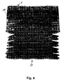
- FIG 4 shows a schematic, perspective view of a partition 27 formed by modules according to an embodiment of the invention, where the uppermost part of the partition is provided with said end modules 11 and 12 comprising edge regions 14 that by bending provide a substantially unbroken edge portion of the partition.
- the partition 27 constitutes in the shown example a substantially planar face of modules, outwardly from which face said outwardly extending protrusions used for attachment of the modules to adjacent modules as shown in figure 3 extend.
- Such a partition composed of modules according to the invention, can by proper choice of modules (for example in relation to choice of material, the composition of the individual module, colour etc.) be given a lot of different characteristics, both relating to appearance, but also relating to acoustical characteristics etc. as mentioned initially.
- figure 5 shows a schematic, perspective view of a section of the edge region of a partition as for instance shown in figure 4.
- Figure 5 thus serves the purpose of illustrating the bending of the end regions of the modules in order to provide the edge region.
- figure 5 there are shown two of the central modules 1 described in connection with figure 1. These are in figure 5 shown as a relatively light lower module 1' and a relatively dark upper module 1". Furthermore, figure 5 shows two end modules, illustrated by dots and short lines, respectively, and comprising the reference numerals 11 (the main body), 14 (said edge region) and 15 and 16 (the protrusions extending in an outward direction from the edge region). As illustrated by the arrows A and B in figure 5, the edge regions are folded such that they overlap partially the outermost region of the corresponding end module, and the protrusion 16 is passed in a backward direction (as seen in the figure) through the corresponding opening 18 in the end module 11.
- the protrusion 5 on the central module 1" is likewise passed in a backward direction through this opening 18.
- the protrusion 15 on the lowermost end module 11 (shown with short lines) is passed in a forward direction (as seen in the figure) through the lowermost opening 18 in the uppermost end module, which also applies to the protrusion 4 of the central (light) module 1'.
- the substantially unbroken edge region of the system or partition is formed, which edge region is thus defined by the bent edge portions 14 and the corresponding end portions of the end modules.
- FIG 6 With reference to figure 6 there is shown a basic module according to a second embodiment of the invention generally referred to by reference .numeral 29.
- This module resembles the one shown in figure 1 to a large extent except for the upper edge portion 29", which resembles the lower edge portion 29' as opposed to the module shown in figure 1, where the upper edge portion is straight.
- Features of the modules shown in figures 1 and 6 are otherwise designated by identical reference numerals.
- FIG 7 An end (or side) module according to a second embodiment of the invention and corresponding essentially to the first embodiment shown in figure 2 is in figure 7 generally referred to by reference numeral 30.
- the upper edge portion 30" differs from the corresponding portion in the module shown in figure 2 in that the upper edge portion 30" of the module according to the second embodiment shown in figure 7 resembles the lower edge portion 30', i.e. the upper edge portion 30" is not straight as in figure 2.
- FIG 8 there is shown a top or bottom module according to the second embodiment of the invention generally indicated by reference numeral 31.
- the use of this module for forming a partition is shown in figure 10.
- the upper edge portion 31" is straight as opposed to the lower edge portion 31'.
- corner modules 32, 33 according to the second embodiment of the invention by means of which it is possible to form a substantially 90 degrees corner portion of for instance a partition, as shown in figure 10.
- FIG 10 there is shown a schematic, plane view of a surface 34 in a room, comprising a door opening 35, where the surface is formed by modules according to the invention.
- the main part of the surface 34 is formed by the modules according either to figure 6 or figure 1 indicated by reference numerals 1, 29, which modules are termed main modules.
- the top portions, bottom portions, end or side portions and corner portions are formed by top and bottom modules 31, side modules 11, 30 and corner modules 32, 33, respectively.
- the various modules according to the invention make it possible to form a surface with substantially straight edge portions that can be adapted to the desired dimensions of walls, etc. of a given room, which surface can even comprise openings in the surface, such as the door opening 35 illustrated in figure 10.
- FIG 11 With reference to figure 11 there is shown a plane view of a portion of a surface formed by main modules 29 according to the invention.
- FIG 12 With reference to figure 12 there is shown a plane view of a corner portion of a surface comprising the four different modules 29 (main), 30 (side), 31 (top) and 32, 33 (corner) according to the invention.
- figure 13 shows a schematic representation of suspension means for a module (or system) according to the invention.
- figure 13 shows a module 31 (and adjacent modules, not shown in figure 13) suspended from for instance a wire 26, as for instance shown in figure 3, which wire 26 is connected via a cable tensioner 36 to a wire 37, which wire is attached to a supporting structure, for instance to a ceiling.
- FIG 14 there is shown schematic views seen from above of systems of modules according to the invention, illustrating the possibility of forming curved portions of surfaces by the modules according to the invention. Different curvatures are designated by reference numerals 38, 39, 40, 41 and 42.
Landscapes
- Engineering & Computer Science (AREA)
- Architecture (AREA)
- Civil Engineering (AREA)
- Structural Engineering (AREA)
- Physics & Mathematics (AREA)
- Electromagnetism (AREA)
- Building Environments (AREA)
- Electrochromic Elements, Electrophoresis, Or Variable Reflection Or Absorption Elements (AREA)
Abstract
Description
- The invention relates to a basic module for a modular screen, which for instance can be assembled to form a flexible partition, the extent, appearance and characteristics of which can be changed according to specific requirements by choosing appropriate modules. The invention furthermore relates to a screen composed of a plurality of modules according to the invention and to a method of forming a screen. The invention furthermore relates to the use of said modules, system and method for attaining given, desired design effects, functional effects and for providing the possibility to apply acoustic control of a room or local areas within a room, for instance around a work place.
- It is an object of the present invention to provide a basic module that is formed such that a plurality of modules can easily be assembled to larger units, for instance a partition. By applying modules of different colours, materials (or covered by different materials) or other characteristics many different appearances of the unit can be attained, which may be of interest at least from a design point of view. Furthermore, a partition according to the invention can by proper choice of materials be given desirable acoustical properties and it may thus be used for acoustical control of a room. Furthermore, the unit according to the invention - or the individual modules according to the invention - can by proper choice of materials be used as a bulletin board. According to a specific embodiment of the invention the modules are made of a textile provided on both opposing sides of a core of a suitable thickness, for
instance 10 to 20 mm, made of PE foam, which is a flameproof and closed-cell foam material. It is, however, understood that also other materials could be used for composing the modules according to the invention and that these also as an alternative could be made in one piece - for instance without upholstering - of a suitable material, provided that this had or was given the necessary flexibility in regions of the module that must be bendable. - The said objects are according to the invention attained by a basic module having for instance a substantially rectangular shape, even though many other shapes would also be conceivable, where at opposing ends of the module outwardly extending protrusions are provided, which can be brought into releasable engagement with co-operating openings in adjacent modules, which openings according to a preferred embodiment are provided centrally in the module.
- In order to assemble and retain a plurality of said modules in a total assemblage of modules, for instance to form a partition as described above, the modules can furthermore be provided with through openings, through which a support structure for instance consisting of wires, cables, rods or belts, etc. can be passed, such that the individual module is supported at its position in the system of modules.
- For assembling a total system, such as a partition, said outwardly extending protrusion is on certain modules provided on end portions of the module that is displaced laterally relative to the module, said end portions being foldable in such a manner that a substantially unbroken edge region of the system, for instance a partition, is attained. The present invention thus relates to both of these basic forms of modules and the corresponding total systems that can be assembled from these modules.
- The present invention furthermore relates to a method of providing a surface, for instance a partition, where the method basically comprises the following steps:
- (a) provision of a plurality of central modules comprising a central body and protrusions extending in an outward direction from said body and through openings provided through said body;
- (b) assembling said surface by bringing said protrusions on each individual of said central modules into releasable engagement with said openings in adjacent modules.
- The invention furthermore relates to the use of said modules, system and method for attaining given, desired design effects, functional effects and for providing the possibility to apply acoustic control of a room or local areas within a room, for instance around a work place.
- The invention will be more fully understood by reading the following detailed description of various embodiments of the invention in conjunction with the figures, where
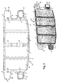
- figure 1 shows a schematic representation of a basic module according to an embodiment of the invention shown in plane view and as a schematic, perspective view;
- figure 2 shows schematic perspective views of end modules (left and right) according to an embodiment of the invention, from which it appears that the two outwardly extending protrusions at one end of the module are provided displaced relative to the main body of the module;
- figure 3 shows a schematic, perspective view of a section of a system of modules according to an embodiment of the invention illustrating engagement between the individual modules and an example of a support structure;
- figure 4 shows a schematic, perspective view of a partition composed of modules according to an embodiment of the invention, where the upper portion of the partition is provided with said end modules, which upon bending provide a substantially unbroken edge portion of the partition;
- figure 5 shows a schematic, perspective view of a section of the edge region of a partition according to the invention, such as shown in figure 4, the figure serving to illustrate the bending of end portions of the modules;
- figure 6 shows a plane view of a first module according to a second embodiment of the invention referred to as a main module;
- figure 7 shows a plane view of a second module according to a second embodiment of the invention referred to as a side module;
- figure 8 shows a plane view of a third module according to a second embodiment of the invention referred to as a top and bottom module;
- figure 9 shows a plane view of a fourth module according to a second embodiment of the invention referred to as a corner module;
- figure 10 shows a schematic, plane view of a surface formed by modules according to the invention and forming a wall or partition including a door opening;
- figure 11 shows a plane view of a portion of a surface formed by modules according to the invention;
- figure 12 shows a plane view of a corner portion of a surface formed by modules according to the invention;
- figure 13 is a schematic representation of a suspension of a module according to the invention; and
- figure 14 illustrates schematically curved portions of a surface formed by modules according to the invention.
- In the following, a more detailed description of embodiments of the module according to the present invention is given and of a system composed of such modules, by which a partition is formed. It should, however, be noted that a person skilled in the art would be able to conceive other embodiments of the basic inventive idea and that such alternative embodiments are regarded as being within the scope of the invention, as defined by the appended claims and technical equivalents of these.
- Referring to figure 1 there is thus shown an embodiment of a basic module according to the invention generally referred to by
reference numeral 1 and comprising a centralmain body 3, which, in the shown embodiment, is provided with a number of thicker, for instance upholsteredareas 2, either on one of the substantially plane sides of the module or on both of these. Centrally in the module there is providedopenings 9 for releasable engagement with corresponding means in adjacent modules. These corresponding means are in the shown embodiment the outwardly extendingprotrusions reference numeral 6 in figure 1. According to a preferred embodiment, said protrusions are thicker or provided with upholstered regions on one side and substantially planar on the other, opposing side, as indicated byreference numeral 10, such that two of these protrusions, when the modules are assembled to form a system, can abut against each other in a face-to-face relationship along the planar surfaces. When modules are assembled to form a system, a givenprotrusion corresponding opening 9 in an adjacent module, which is made possible by the flexibility of the materials used and the protrusion thereby locks releasably in the opening by engagement between therecesses 8 with the corresponding edge portions of theopenings 9. Furthermore, the module according to the shown embodiment is provided with throughopenings 7 for passage of the above mentioned support structure, which will be shown in figure 3. - With reference to figure 2 there is shown left and
right end modules - The left and right end modules are in the shown embodiment mirror symmetric and both comprise a
central body 3. The end modules differ from the module described in connection with figure 1 primarily in that theend modules edge region 14, on which there is provided outwardly extending protrusions of the same kind as described previously. The lowermost (as seen in the figure) of theseprotrusions 16 is placed so that by bending theedge region 14 inwardly over themodules corresponding opening 18 in the module, while the upper protrusion can be passed through an opening in an adjacent module, as shown more clearly in figure 5. Apart from said differences theend modules central modules 1, described in connection with figure 1. - With reference to figure 3 there is shown a schematic perspective view of a section of a
system 24 of modules according to an embodiment of the invention, which among others illustrates the engagement between the individual modules and an example of a support structure. This support structure consists in the shown embodiment of the system according to the invention of a number of horizontally extending cables or the like 25 that are mutually connected with hook-like members 28, whereby a fixed skeleton for the system of modules is formed. Theindividual cables 25 are passed through theopenings 7 in the modules. In the figure, the system is furthermore shown suspended atreference numeral 26. The shown section of the system comprises three rows R1, R2 and R3 of modules arranged above each other, said modules being connected with each other in such a manner that they partially overlap each other in a manner corresponding somewhat to the tiles on a roof. It appears from figure 3 that the outwardly extendingprotrusions corresponding openings 9 in the modules placed behind and in front of the given module, respectively. In this manner there is formed a substantially continuous surface of modules (as shown in figure 4). This surface can be planar, but due to the flexibility of the modules it is also possible to construct different forms of curved surfaces. - An example of a system according to the invention constructed in principle as shown in figure 3 is illustrated in figure 4 that shows a schematic, perspective view of a partition 27 formed by modules according to an embodiment of the invention, where the uppermost part of the partition is provided with said
end modules edge regions 14 that by bending provide a substantially unbroken edge portion of the partition. The partition 27 constitutes in the shown example a substantially planar face of modules, outwardly from which face said outwardly extending protrusions used for attachment of the modules to adjacent modules as shown in figure 3 extend. Such a partition, composed of modules according to the invention, can by proper choice of modules (for example in relation to choice of material, the composition of the individual module, colour etc.) be given a lot of different characteristics, both relating to appearance, but also relating to acoustical characteristics etc. as mentioned initially. - The provision of an essentially unbroken edge region of the system by means of the
end modules - With reference to figure 5 there are shown two of the
central modules 1 described in connection with figure 1. These are in figure 5 shown as a relatively light lower module 1' and a relatively darkupper module 1". Furthermore, figure 5 shows two end modules, illustrated by dots and short lines, respectively, and comprising the reference numerals 11 (the main body), 14 (said edge region) and 15 and 16 (the protrusions extending in an outward direction from the edge region). As illustrated by the arrows A and B in figure 5, the edge regions are folded such that they overlap partially the outermost region of the corresponding end module, and theprotrusion 16 is passed in a backward direction (as seen in the figure) through thecorresponding opening 18 in theend module 11. Theprotrusion 5 on thecentral module 1" is likewise passed in a backward direction through thisopening 18. Theprotrusion 15 on the lowermost end module 11 (shown with short lines) is passed in a forward direction (as seen in the figure) through thelowermost opening 18 in the uppermost end module, which also applies to theprotrusion 4 of the central (light) module 1'. In the manner illustrated, the substantially unbroken edge region of the system or partition is formed, which edge region is thus defined by thebent edge portions 14 and the corresponding end portions of the end modules. - With reference to figure 6 there is shown a basic module according to a second embodiment of the invention generally referred to by reference .
numeral 29. This module resembles the one shown in figure 1 to a large extent except for theupper edge portion 29", which resembles the lower edge portion 29' as opposed to the module shown in figure 1, where the upper edge portion is straight. Features of the modules shown in figures 1 and 6 are otherwise designated by identical reference numerals. - An end (or side) module according to a second embodiment of the invention and corresponding essentially to the first embodiment shown in figure 2 is in figure 7 generally referred to by
reference numeral 30. Theupper edge portion 30" differs from the corresponding portion in the module shown in figure 2 in that theupper edge portion 30" of the module according to the second embodiment shown in figure 7 resembles the lower edge portion 30', i.e. theupper edge portion 30" is not straight as in figure 2. - Referring to figure 8 there is shown a top or bottom module according to the second embodiment of the invention generally indicated by
reference numeral 31. The use of this module for forming a partition is shown in figure 10. In this module theupper edge portion 31" is straight as opposed to the lower edge portion 31'. - Referring to figure 9 there is shown
corner modules - With reference to figure 10 there is shown a schematic, plane view of a surface 34 in a room, comprising a
door opening 35, where the surface is formed by modules according to the invention. The main part of the surface 34 is formed by the modules according either to figure 6 or figure 1 indicated byreference numerals bottom modules 31,side modules corner modules - With reference to figure 11 there is shown a plane view of a portion of a surface formed by
main modules 29 according to the invention. - With reference to figure 12 there is shown a plane view of a corner portion of a surface comprising the four different modules 29 (main), 30 (side), 31 (top) and 32, 33 (corner) according to the invention.
- With reference to figure 13 there is shown a schematic representation of suspension means for a module (or system) according to the invention. Thus, figure 13 shows a module 31 (and adjacent modules, not shown in figure 13) suspended from for instance a
wire 26, as for instance shown in figure 3, whichwire 26 is connected via acable tensioner 36 to awire 37, which wire is attached to a supporting structure, for instance to a ceiling. - Finally with reference to figure 14 there is shown schematic views seen from above of systems of modules according to the invention, illustrating the possibility of forming curved portions of surfaces by the modules according to the invention. Different curvatures are designated by
reference numerals
Claims (15)
- A basic module comprising a central body (3), at opposite ends of said body (3) being provided with protrusions (4, 5, 15, 16) extending in an outward direction from said body (3), where the body (3) is furthermore provided with through openings (9), through which openings (9) protrusions provided on adjacent modules can pass, thereby providing releasable engagement between a given opening (9) and a corresponding protrusion (4, 5, 15, 16).
- A basic module according to claim 1, characterised in that the module furthermore comprises through openings (7), through which portions of a support structure can be passed.
- A basic module according to claim 1, characterised in that the module furthermore comprises a number of thicker portions (2) that can for instance be upholstered.
- A basic module according to claim 1, characterised in that said protrusions (15, 16) are provided on an edge portion (14) connected to the central body (3) and laterally displaced relative to the central body (3).
- A basic module according to claim 4, characterised in that said central body (3) is furthermore provided with through openings (18), through which said protrusions (15, 16) provided on said edge portion (14) can pass, when the edge portion (14) is bent over the corresponding portion of an end region of the central body (3).
- A basic module according to any of the preceding claims, characterised in that the module is made of textile provided on either side of a core.
- A basic module according to claim 6, characterised in that the thickness of the core is in the range of 10 to 20 mm.
- A basic module according to claim 6, characterised in that the core is made of PE foam.
- A system of basic modules according to any of the preceding claims 1 to 8, characterised in that the system comprises a support structure (25, 26, 28) comprising support means (25) passed through said openings (7) in individual modules.
- A system according to claim 9, characterised in that said support structure furthermore comprises connecting members (28) that connect an individual of said means (25) with adjacent support means.
- A system according to claim 9 or 10, characterised in that the system furthermore comprises means (26) for suspending the system.
- A system according to any of the preceding claims 9 to 11, characterised in that the system comprises main modules (1, 29), side modules (11, 12, 30), top and bottom modules (31) and corner modules (32, 33), whereby a surface comprising substantially straight edge portions and substantially 90 degrees corner portions can be provided.
- The use according to claim 12, where said partition or surface structure is used for decorative purposes and/or for fastening objects to the partition or surface and/or for acoustic control of a room or other space, where the partition or surface is provided.
- A method for establishing a surface, such as a partition, the method comprising the following steps:(a) the provision of a plurality of central modules (1) comprising a central body (3) and protrusions (4, 5) extending in outward directions from end regions of said body (3) and through openings (9) through the body (3);(b) assembling said surface by bringing said protrusions (4, 5) on each individual of said central modules (1) into releasable engagement with said openings (9) in adjacent modules (1).
- The use of modules according to the invention for controlling the acoustics of a room or other space.
Applications Claiming Priority (1)
| Application Number | Priority Date | Filing Date | Title |
|---|---|---|---|
| DKPA200600178 | 2006-02-08 |
Publications (2)
| Publication Number | Publication Date |
|---|---|
| EP1818470A2 true EP1818470A2 (en) | 2007-08-15 |
| EP1818470A3 EP1818470A3 (en) | 2008-04-30 |
Family
ID=38016625
Family Applications (1)
| Application Number | Title | Priority Date | Filing Date |
|---|---|---|---|
| EP07002610A Withdrawn EP1818470A3 (en) | 2006-02-08 | 2007-02-07 | A basic module for a modular screen for display or partition |
Country Status (2)
| Country | Link |
|---|---|
| US (1) | US20070193217A1 (en) |
| EP (1) | EP1818470A3 (en) |
Cited By (2)
| Publication number | Priority date | Publication date | Assignee | Title |
|---|---|---|---|---|
| WO2010001359A1 (en) | 2008-07-04 | 2010-01-07 | Kvadrat A/S | A modular system for partition or cladding |
| PT106412A (en) * | 2012-06-28 | 2013-12-30 | Univ Do Minho | ADAPTABLE PANEL DIVISIONS SYSTEM AND CONSTRUCTION METHOD |
Citations (2)
| Publication number | Priority date | Publication date | Assignee | Title |
|---|---|---|---|---|
| US4462145A (en) | 1981-02-23 | 1984-07-31 | Schulze Herbert C | Method of making a portable and collapsed structure |
| US5687526A (en) | 1995-11-08 | 1997-11-18 | Benvenuto; Guido | Trackless drop ceiling system |
Family Cites Families (12)
| Publication number | Priority date | Publication date | Assignee | Title |
|---|---|---|---|---|
| US3533206A (en) * | 1968-07-16 | 1970-10-13 | James K Passeno Jr | Building block holder for fabricating veneer walls |
| US3666607A (en) * | 1968-09-03 | 1972-05-30 | Joel J Weissman | Blank for constructing solid forms |
| US3696567A (en) * | 1970-12-21 | 1972-10-10 | Ibs Industrialized Building Sy | Prefabricated building panel having positioner means |
| US4454678A (en) * | 1981-12-07 | 1984-06-19 | Duvivier John E | Slotted panels with slotted connectors |
| US5323836A (en) * | 1992-03-13 | 1994-06-28 | Boise Cascade Corporation | Modular portable display screen |
| US5375641A (en) * | 1993-05-11 | 1994-12-27 | Good Impressions, Inc. | Modular panel system |
| US5611384A (en) * | 1995-08-28 | 1997-03-18 | Carter; Wallace T. | Display system |
| US5895306A (en) * | 1996-01-10 | 1999-04-20 | Seven Towns Limited | Polygonal puzzle kit capable of three-dimensional construction, such as toy construction |
| US5778959A (en) * | 1996-08-23 | 1998-07-14 | Guetschow; Keith | Portable display screen |
| US6179681B1 (en) * | 1998-02-13 | 2001-01-30 | Jose R. Matos | Universal connector toy |
| EP1345303A1 (en) * | 2002-03-13 | 2003-09-17 | Reinhard Vigl | Fastening means comprising a flush mounted box and a mounting holder |
| US7086190B2 (en) * | 2004-01-28 | 2006-08-08 | Voluckas Stanley A | Display system for suspending visuals for exhibit, training or advertising |
-
2007
- 2007-02-07 EP EP07002610A patent/EP1818470A3/en not_active Withdrawn
- 2007-02-07 US US11/672,205 patent/US20070193217A1/en not_active Abandoned
Patent Citations (2)
| Publication number | Priority date | Publication date | Assignee | Title |
|---|---|---|---|---|
| US4462145A (en) | 1981-02-23 | 1984-07-31 | Schulze Herbert C | Method of making a portable and collapsed structure |
| US5687526A (en) | 1995-11-08 | 1997-11-18 | Benvenuto; Guido | Trackless drop ceiling system |
Cited By (4)
| Publication number | Priority date | Publication date | Assignee | Title |
|---|---|---|---|---|
| WO2010001359A1 (en) | 2008-07-04 | 2010-01-07 | Kvadrat A/S | A modular system for partition or cladding |
| CN101849072B (en) * | 2008-07-04 | 2012-07-11 | 克瓦德拉特股份公司 | A modular system for partition or cladding |
| PT106412A (en) * | 2012-06-28 | 2013-12-30 | Univ Do Minho | ADAPTABLE PANEL DIVISIONS SYSTEM AND CONSTRUCTION METHOD |
| EP2679739A2 (en) | 2012-06-28 | 2014-01-01 | Universidade do Minho | Partition system |
Also Published As
| Publication number | Publication date |
|---|---|
| EP1818470A3 (en) | 2008-04-30 |
| US20070193217A1 (en) | 2007-08-23 |
Similar Documents
| Publication | Publication Date | Title |
|---|---|---|
| US11098481B2 (en) | Canopy system and group suspension system therefore | |
| US6189270B1 (en) | Panel wall construction | |
| US5375641A (en) | Modular panel system | |
| US8365449B2 (en) | Configurable large-depth panel display | |
| US20220056690A1 (en) | Ceiling system and method of installation | |
| US20240229459A1 (en) | Ceiling system and method of installation | |
| EP1068410A1 (en) | Wall panel partition system | |
| US6354043B1 (en) | Privacy screen and method for systems furniture and the like | |
| US12018486B2 (en) | Ceiling system and method of installation | |
| US20250341093A1 (en) | Architectural fixture connection system | |
| EP1818470A2 (en) | A basic module for a modular screen for display or partition | |
| EP3008257B1 (en) | Modular wall installation | |
| EP2307628B1 (en) | A modular system for partition or cladding | |
| EP1425482A1 (en) | Decorative structure and ceiling system | |
| EP1612340B1 (en) | Baffle system for a suspended ceiling | |
| US20060130417A1 (en) | Decorative structure and ceiling system | |
| US9528287B2 (en) | Angled wall connection devices, systems, and methods | |
| JP3209713U (en) | Decorative material | |
| CA2838196C (en) | Angled wall connection devices, systems, and methods | |
| SE2150953A1 (en) | A wall module | |
| JP6748751B1 (en) | Unit furniture | |
| JPH01142151A (en) | Ceiling structure | |
| HK1145700B (en) | A modular system for partition or cladding | |
| IT201600081636A1 (en) | SYSTEM FOR THE PARTITION OF AN ENVIRONMENT |
Legal Events
| Date | Code | Title | Description |
|---|---|---|---|
| PUAI | Public reference made under article 153(3) epc to a published international application that has entered the european phase |
Free format text: ORIGINAL CODE: 0009012 |
|
| AK | Designated contracting states |
Kind code of ref document: A2 Designated state(s): AT BE BG CH CY CZ DE DK EE ES FI FR GB GR HU IE IS IT LI LT LU LV MC NL PL PT RO SE SI SK TR |
|
| AX | Request for extension of the european patent |
Extension state: AL BA HR MK YU |
|
| PUAL | Search report despatched |
Free format text: ORIGINAL CODE: 0009013 |
|
| AK | Designated contracting states |
Kind code of ref document: A3 Designated state(s): AT BE BG CH CY CZ DE DK EE ES FI FR GB GR HU IE IS IT LI LT LU LV MC NL PL PT RO SE SI SK TR |
|
| AX | Request for extension of the european patent |
Extension state: AL BA HR MK RS |
|
| 17P | Request for examination filed |
Effective date: 20081030 |
|
| AKX | Designation fees paid |
Designated state(s): AT BE BG CH CY CZ DE DK EE ES FI FR GB GR HU IE IS IT LI LT LU LV MC NL PL PT RO SE SI SK TR |
|
| STAA | Information on the status of an ep patent application or granted ep patent |
Free format text: STATUS: THE APPLICATION IS DEEMED TO BE WITHDRAWN |
|
| 18D | Application deemed to be withdrawn |
Effective date: 20100901 |