EP1818193A1 - Tire pressure monitoring apparatus - Google Patents
Tire pressure monitoring apparatus Download PDFInfo
- Publication number
- EP1818193A1 EP1818193A1 EP07002331A EP07002331A EP1818193A1 EP 1818193 A1 EP1818193 A1 EP 1818193A1 EP 07002331 A EP07002331 A EP 07002331A EP 07002331 A EP07002331 A EP 07002331A EP 1818193 A1 EP1818193 A1 EP 1818193A1
- Authority
- EP
- European Patent Office
- Prior art keywords
- valve stem
- pressure transducer
- monitoring apparatus
- spring member
- tire pressure
- Prior art date
- Legal status (The legal status is an assumption and is not a legal conclusion. Google has not performed a legal analysis and makes no representation as to the accuracy of the status listed.)
- Withdrawn
Links
- 238000012544 monitoring process Methods 0.000 title claims abstract description 24
- 239000011324 bead Substances 0.000 claims description 10
- 238000003780 insertion Methods 0.000 claims description 5
- 230000037431 insertion Effects 0.000 claims 1
- 238000013461 design Methods 0.000 description 3
- 229910000831 Steel Inorganic materials 0.000 description 2
- 230000006835 compression Effects 0.000 description 2
- 238000007906 compression Methods 0.000 description 2
- 238000009434 installation Methods 0.000 description 2
- 230000007246 mechanism Effects 0.000 description 2
- 238000012986 modification Methods 0.000 description 2
- 230000004048 modification Effects 0.000 description 2
- 239000012858 resilient material Substances 0.000 description 2
- 229910001220 stainless steel Inorganic materials 0.000 description 2
- 239000010935 stainless steel Substances 0.000 description 2
- 239000010959 steel Substances 0.000 description 2
- 229910000906 Bronze Inorganic materials 0.000 description 1
- 230000000712 assembly Effects 0.000 description 1
- 238000000429 assembly Methods 0.000 description 1
- 238000005452 bending Methods 0.000 description 1
- 239000010974 bronze Substances 0.000 description 1
- KUNSUQLRTQLHQQ-UHFFFAOYSA-N copper tin Chemical compound [Cu].[Sn] KUNSUQLRTQLHQQ-UHFFFAOYSA-N 0.000 description 1
- 238000000034 method Methods 0.000 description 1
- 230000008569 process Effects 0.000 description 1
- 238000007789 sealing Methods 0.000 description 1
Images





Classifications
-
- B—PERFORMING OPERATIONS; TRANSPORTING
- B60—VEHICLES IN GENERAL
- B60C—VEHICLE TYRES; TYRE INFLATION; TYRE CHANGING; CONNECTING VALVES TO INFLATABLE ELASTIC BODIES IN GENERAL; DEVICES OR ARRANGEMENTS RELATED TO TYRES
- B60C23/00—Devices for measuring, signalling, controlling, or distributing tyre pressure or temperature, specially adapted for mounting on vehicles; Arrangement of tyre inflating devices on vehicles, e.g. of pumps or of tanks; Tyre cooling arrangements
- B60C23/02—Signalling devices actuated by tyre pressure
- B60C23/04—Signalling devices actuated by tyre pressure mounted on the wheel or tyre
- B60C23/0408—Signalling devices actuated by tyre pressure mounted on the wheel or tyre transmitting the signals by non-mechanical means from the wheel or tyre to a vehicle body mounted receiver
-
- B—PERFORMING OPERATIONS; TRANSPORTING
- B60—VEHICLES IN GENERAL
- B60C—VEHICLE TYRES; TYRE INFLATION; TYRE CHANGING; CONNECTING VALVES TO INFLATABLE ELASTIC BODIES IN GENERAL; DEVICES OR ARRANGEMENTS RELATED TO TYRES
- B60C23/00—Devices for measuring, signalling, controlling, or distributing tyre pressure or temperature, specially adapted for mounting on vehicles; Arrangement of tyre inflating devices on vehicles, e.g. of pumps or of tanks; Tyre cooling arrangements
- B60C23/02—Signalling devices actuated by tyre pressure
- B60C23/04—Signalling devices actuated by tyre pressure mounted on the wheel or tyre
- B60C23/0491—Constructional details of means for attaching the control device
- B60C23/0494—Valve stem attachments positioned inside the tyre chamber
Definitions
- the present invention relates to a tire pressure monitoring apparatus and, in particular, relates to a unitized tire pressure monitoring apparatus with features that facilitate installation on various vehicle wheel configurations.
- Tire pressure monitoring (“TPM”) systems are known in the art. There have been several mounting arrangements proposed for these TPM systems and apparatuses. Some of the proposed mounting arrangements are shown in U.S. Patents No. 6,163,255 , No. 6,722,409 , No. 6,568,259 , and No. 6,799,455 .
- TPM sensors are rapidly becoming a commodity, and OEMs are attempting to use one part for multiple platform applications with simplified assembly while maintaining current assembly processes.
- the challenge for the TPM sensor is providing a single TPM sensor configuration that is capable of being mounted rigidly to a wide range of wheel rim thicknesses and configurations, while maintaining the current "snap-in" valve design and continued sealing performance over high speeds.
- a unitized tire pressure monitoring system facilitates installation on various vehicle wheel configurations.
- the present invention relates to a tire pressure monitoring apparatus that includes a pressure transducer and a valve stem.
- a spring member connects the pressure transducer to the valve stem. The spring member facilitates relative movement between the pressure transducer and the valve stem.
- a tire pressure monitoring (“TPM”) apparatus or sensor 10 includes a valve stem 12 and a pressure transducer 14 with a housing 16.
- the TPM sensor 10 is configured to be mounted on a vehicle wheel 50 (Figs. 2-4) in a manner described in further detail below.
- the valve stem 12 includes a valve mechanism (not shown) that allows for selectively inflating or deflating a tire (not shown) mounted on the wheel 50, as known in the art.
- the pressure transducer 14 is operative to sense the inflation pressure of the tire and provide a signal, indicative of the sensed pressure, to a vehicle mounted apparatus (not shown); such as a controller.
- the TPM sensor 10 includes a spring member 20 for helping to support the valve stem 12, or portions thereof, for movement relative to the pressure transducer 14.
- the spring member 20 comprises a helical spring supported in a spring housing portion 22 of the pressure transducer 14.
- the valve stem 12 includes a plunger member 24 that has a portion positioned in the spring housing 22 and movable relative to the housing along an axis 26.
- the plunger member 24 is movable along the axis 26 relative to the spring housing 22 against the bias of the spring member 20.
- the spring member 20 is constructed of a flexible resilient material, such as steel (e.g., stainless steel). The spring member 20 thus may permit the valve stem 12 and the pressure transducer 14 to move relative to each other through compression or tension.
- the spring member 20 is configured for compression when the plunger member 24 moves along the axis 26 relative to the spring housing 22.
- the spring member 20 could be configured to be tensioned when the plunger member 24 moves along the axis 26 relative to the spring housing 22.
- the configuration of the TPM sensor 10 illustrated in Figs. 1-4 and described above is a "snap-in" design capable of being mounted to the vehicle wheel 50 without the use of separate fasteners.
- the TPM sensor 10 is secured to the wheel 50 by inserting the valve stem 12 through a stem opening 52 in the wheel.
- the pressure transducer 14 engages an inner surface 54 of the wheel 50. More particularly, support tegs 40 of the pressure transducer 14 engage the inner surface 54 of the wheel 50.
- valve stem 12 To seat and seal the value stem 12 in the opening 52, the valve stem is moved through the opening 52 until the annular portion of the wheel 50 that defines the opening snaps into and is received in an annular recess 42 formed by an annular bead 44 of the valve stem 12.
- the valve stem To achieve a proper seating and seal between the valve stem 12 and the wheel 50, the valve stem is over-inserted, i.e., moved beyond the position shown in Fig. 2 to the position shown in Fig. 3. As shown in Fig, 3, this causes the valve stem 12 to stretch, deflect, or otherwise deform so that the annular bead 44 extends through the opening 52 and beyond to an extend sufficient to help ensure a proper seat. Thereafter, the valve stem 12 is released, at which time the valve stem snaps back to the seated and sealed position shown in Fig. 4.
- the spring member 20 permitting rotative movement between the valve stem 12 and the pressure transducer 14, allows the valve stem 12 to stretch, deflect, or otherwise deform to a degree sufficient to permit the over-insertion of the stem that facilitates the snap fit of the stem onto the wheel.
- the spring member 20 may permit the valve stem 12 to stretch, deflect, or otherwise deform up to 6 millimeters or more beyond the opening 52.
- the spring member 20 may exert a spring bias that maintains the pressure transducer 14 (e.g., the legs 40) in contact with the inner surface 54 of the wheel 50.
- the spring member 20 thus may help support the pressure transducer 14 on the wheel 50 and may help prevent shaking, rattling, or other undesirable movement of the pressure-transducer relative to the wheel.
- the TPM sensor 10 may be configured such that the valve stem 12 and the pressure transducer 14 extend at an angle with each other, as indicated generally at X in Fig. 4.
- This angle may help position the pressure transducer 14 relative to the wheel 50 such that the pressure transducer is maintained at a position below a bead hump 58 of the wheel 50. This provides a clearance that helps prevent disturbance of the pressure transducer 14 when tires are mounted to or dismounted from the wheel 50.
- a tire pressure monitoring (“TPM”) apparatus or sensor 110 includes a valve stem 112 and a pressure transducer 114 with a housing 116.
- the TPM sensor 110 is configured to be mounted on a vehicle wheel 150 in a manner described in further detail below.
- the valve stem 112 includes a valve mechanism (not shown) that allows for selectively inflating or deflating a tire (not shown) mounted on the wheel 150, as known in the art.
- the pressure transducer 114 is operative to sense the inflation pressure of the tire and provide a signal, indicative of the sensed pressure, to a vehicle mounted apparatus (not shown), such as a controller.
- the TPM sensor 110 includes a spring member 120 for helping to support the valve stem 112 for movement relative to the pressure transducer 114.
- the spring member 120 includes a central ring portion 122 that encircles a portion 124 of the valve stem 112, thereby securing the spring member to the valve stem.
- the spring member 120 has end portions 126 on opposite sides of the ring portion 122 that engage the pressure transducer 114 to secure the spring member to the transducer.
- the valve stem 112 and pressure transducer 114 are interconnected via the spring member 120.
- the spring member 120 also includes spring portions 130 that extend between the ring portion 122 and the end portions 126.
- Each spring portion 130 includes parallel spring members 132 that are connected to each other, to the ring portion 122, and to the end portions 126 by respective curved portions 134.
- the spring member 120 and, thus, the spring portions 130 are constructed of a flexible resilient material, such as bronze or steel (e.g., stainless steel). The spring member 120 thus may permit the valve stem 112 and the pressure transducer 114 to move relative to each other through bending or deflection of the spring portions 130.
- the configuration of the TPM sensor 110 illustrated in Figs. 5-8 and described above is a "snap-in" design capable of being mounted to the vehicle wheel 150 without the use of separate fasteners.
- the TPM sensor 110 is secured to the wheel 150 by inserting the valve stem 112 through a stem opening 152 in the wheel.
- the pressure transducer 114 engages an inner surface 154 of the wheel 150. More particularly, support legs 140 of the pressure transducer 114 engage the inner surface 154 of the wheel 150.
- valve stem 112 To seat and seal the valve stem 112 in the opening 152, the valve stem is moved through the opening 152 until the annular portion of the wheel 150 that defines the opening snaps into and is received in an annular recess 142 formed by an annular bead 144 of the valve stem 112.
- the valve stem To achieve a proper seating and seal between the valve stem 112 and the wheel 150, the valve stem is over-inserted, i.e., moved beyond the position shown in Fig. 6 to the position shown in Fig. 7. As shown in Fig. 7, this causes the valve stem 112 to stretch, deflect, or otherwise deform so that the annular bead 144 extends through the opening 152 and beyond to an extend sufficient to help ensure a proper seal. Thereafter, the valve stem 112 is released, at which time the valve stem snaps back to the seated and seated position shown in Fig. 8.
- the spring member 120 permitting relative movement between the valve stem 112 and the pressure transducer 114, allows the valve stem 112 to stretch, deflect, or otherwise deform to a degree sufficient to permit the over-insertion of the stem that facilitates the snap fit of the stem onto the wheel.
- the spring member 120 may permit the valve stem 112 to stretch, deflect, or otherwise deform up to 6 millimeters or more beyond the opening 152.
- the spring member 120 may exert a spring bias that maintains the pressure transducer 114 (e.g., the legs 140) in contact with the inner surface 154 of the wheel 150.
- the spring member 120 thus may help support the pressure transducer 114 on the wheel 150 and may help prevent shaking, rattling, or other undesirable movement of the pressure transducer relative to the Wheel.
- the TPM sensor 110 may be configured such that the valve stem 112 and the pressure transducer 114 extend at an angle with each other in a manner similar to that shown in the embodiment of figs. 1-4.
- This angle may help position the pressure transducer 114 relative to the wheel 150 such that the pressure transducer is maintained at a position below a bead hump (not shown) of the wheel 150. This provides a clearance that helps prevent disturbance of the pressure transducer 114 when tires are mounted to or dismounted from the wheel 150.
Landscapes
- Engineering & Computer Science (AREA)
- Mechanical Engineering (AREA)
- Measuring Fluid Pressure (AREA)
- Valve Housings (AREA)
- Check Valves (AREA)
Abstract
Description
- This application claims priority from
U.S. provisional patent application Serial No. 60/764,556, filed on February 2, 2006 - The present invention relates to a tire pressure monitoring apparatus and, in particular, relates to a unitized tire pressure monitoring apparatus with features that facilitate installation on various vehicle wheel configurations.
- Tire pressure monitoring ("TPM") systems are known in the art. There have been several mounting arrangements proposed for these TPM systems and apparatuses. Some of the proposed mounting arrangements are shown in
U.S. Patents No. 6,163,255 ,No. 6,722,409 ,No. 6,568,259 , andNo. 6,799,455 . - The automotive industry is driving to reduce the number of part numbers used for vehicle assembly The industry is also attempting to reduce labor in plants and cost from suppliers for purchased assemblies. TPM sensors are rapidly becoming a commodity, and OEMs are attempting to use one part for multiple platform applications with simplified assembly while maintaining current assembly processes. The challenge for the TPM sensor is providing a single TPM sensor configuration that is capable of being mounted rigidly to a wide range of wheel rim thicknesses and configurations, while maintaining the current "snap-in" valve design and continued sealing performance over high speeds.
- In accordance with the present invention, a unitized tire pressure monitoring system facilitates installation on various vehicle wheel configurations. In one aspect, the present invention relates to a tire pressure monitoring apparatus that includes a pressure transducer and a valve stem. A spring member connects the pressure transducer to the valve stem. The spring member facilitates relative movement between the pressure transducer and the valve stem.
- The foregoing and other features and advantages of the present invention will become apparent to those skilled in the art to which the present invention relates upon reading the following description with reference to the accompanying drawings, in which :
- Fig. 1 is a perspective view of a tire pressure monitoring apparatus in accordance with a first embodiment of the present invention;
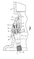
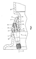
- Figs. 2-4 are side views, partially in section, illustrating the manner in which the tire pressure monitoring apparatus of Fig. 1 is mounted to a vehicle wheel;
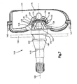
- Fig. 5 is a perspective view of a tire pressure monitoring apparatus in accordance with a second embodiment of the present invention and
- Figs. 6-8 are side views, partially in section, illustrating the manner in which the tire pressure monitoring apparatus of Fig. 5 is mounted to a vehicle wheel,
- Referring to Figs. 1-4, according to a first embodiment of the present invention, a tire pressure monitoring ("TPM") apparatus or
sensor 10 includes avalve stem 12 and apressure transducer 14 with ahousing 16. TheTPM sensor 10 is configured to be mounted on a vehicle wheel 50 (Figs. 2-4) in a manner described in further detail below. Thevalve stem 12 includes a valve mechanism (not shown) that allows for selectively inflating or deflating a tire (not shown) mounted on thewheel 50, as known in the art. Thepressure transducer 14 is operative to sense the inflation pressure of the tire and provide a signal, indicative of the sensed pressure, to a vehicle mounted apparatus (not shown); such as a controller. - According to the first embodiment of the present invention, the
TPM sensor 10 includes aspring member 20 for helping to support thevalve stem 12, or portions thereof, for movement relative to thepressure transducer 14. As shown in Figs. 2-4, thespring member 20 comprises a helical spring supported in aspring housing portion 22 of thepressure transducer 14. Thevalve stem 12 includes aplunger member 24 that has a portion positioned in thespring housing 22 and movable relative to the housing along anaxis 26. - The
plunger member 24 is movable along theaxis 26 relative to thespring housing 22 against the bias of thespring member 20. Thespring member 20 is constructed of a flexible resilient material, such as steel (e.g., stainless steel). Thespring member 20 thus may permit thevalve stem 12 and thepressure transducer 14 to move relative to each other through compression or tension. In the embodiment illustrated in Figs. 1-3, thespring member 20 is configured for compression when theplunger member 24 moves along theaxis 26 relative to thespring housing 22. Those skilled in the art, however, will appreciate that thespring member 20 could be configured to be tensioned when theplunger member 24 moves along theaxis 26 relative to thespring housing 22. - The configuration of the
TPM sensor 10 illustrated in Figs. 1-4 and described above is a "snap-in" design capable of being mounted to thevehicle wheel 50 without the use of separate fasteners. Referring to Fig. 2; theTPM sensor 10 is secured to thewheel 50 by inserting thevalve stem 12 through a stem opening 52 in the wheel. Referring to Fig. 3, as thevalve stem 12 is moved through theopening 52, thepressure transducer 14 engages aninner surface 54 of thewheel 50. More particularly, supporttegs 40 of thepressure transducer 14 engage theinner surface 54 of thewheel 50. - To seat and seal the
value stem 12 in theopening 52, the valve stem is moved through theopening 52 until the annular portion of thewheel 50 that defines the opening snaps into and is received in anannular recess 42 formed by anannular bead 44 of thevalve stem 12. To achieve a proper seating and seal between thevalve stem 12 and thewheel 50, the valve stem is over-inserted, i.e., moved beyond the position shown in Fig. 2 to the position shown in Fig. 3. As shown in Fig, 3, this causes thevalve stem 12 to stretch, deflect, or otherwise deform so that theannular bead 44 extends through theopening 52 and beyond to an extend sufficient to help ensure a proper seat. Thereafter, thevalve stem 12 is released, at which time the valve stem snaps back to the seated and sealed position shown in Fig. 4. - According to the present invention, the
spring member 20, permitting rotative movement between thevalve stem 12 and thepressure transducer 14, allows thevalve stem 12 to stretch, deflect, or otherwise deform to a degree sufficient to permit the over-insertion of the stem that facilitates the snap fit of the stem onto the wheel. For example, thespring member 20 may permit thevalve stem 12 to stretch, deflect, or otherwise deform up to 6 millimeters or more beyond theopening 52. - Once the
bead 44 of thevalve stem 20 is seated against thewheel 50, thespring member 20 may exert a spring bias that maintains the pressure transducer 14 (e.g., the legs 40) in contact with theinner surface 54 of thewheel 50. Thespring member 20 thus may help support thepressure transducer 14 on thewheel 50 and may help prevent shaking, rattling, or other undesirable movement of the pressure-transducer relative to the wheel. As shown in Figs. 2-4, theTPM sensor 10 may be configured such that thevalve stem 12 and thepressure transducer 14 extend at an angle with each other, as indicated generally at X in Fig. 4. This angle may help position thepressure transducer 14 relative to thewheel 50 such that the pressure transducer is maintained at a position below abead hump 58 of thewheel 50. This provides a clearance that helps prevent disturbance of thepressure transducer 14 when tires are mounted to or dismounted from thewheel 50. - Referring to Figs. 5-8, according to a second embodiment of the present invention, a tire pressure monitoring ("TPM") apparatus or
sensor 110 includes avalve stem 112 and apressure transducer 114 with ahousing 116. TheTPM sensor 110 is configured to be mounted on avehicle wheel 150 in a manner described in further detail below. Thevalve stem 112 includes a valve mechanism (not shown) that allows for selectively inflating or deflating a tire (not shown) mounted on thewheel 150, as known in the art. Thepressure transducer 114 is operative to sense the inflation pressure of the tire and provide a signal, indicative of the sensed pressure, to a vehicle mounted apparatus (not shown), such as a controller. - According to the second embodiment of the present invention, the
TPM sensor 110 includes aspring member 120 for helping to support thevalve stem 112 for movement relative to thepressure transducer 114. Thespring member 120 includes acentral ring portion 122 that encircles aportion 124 of thevalve stem 112, thereby securing the spring member to the valve stem. Thespring member 120 hasend portions 126 on opposite sides of thering portion 122 that engage thepressure transducer 114 to secure the spring member to the transducer. Thus, in the embodiment of Figs. 5-8, thevalve stem 112 andpressure transducer 114 are interconnected via thespring member 120. - The
spring member 120 also includesspring portions 130 that extend between thering portion 122 and theend portions 126. Eachspring portion 130 includesparallel spring members 132 that are connected to each other, to thering portion 122, and to theend portions 126 by respectivecurved portions 134. Thespring member 120 and, thus, thespring portions 130, are constructed of a flexible resilient material, such as bronze or steel (e.g., stainless steel). Thespring member 120 thus may permit thevalve stem 112 and thepressure transducer 114 to move relative to each other through bending or deflection of thespring portions 130. - The configuration of the
TPM sensor 110 illustrated in Figs. 5-8 and described above is a "snap-in" design capable of being mounted to thevehicle wheel 150 without the use of separate fasteners. Referring to Fig. 6, theTPM sensor 110 is secured to thewheel 150 by inserting thevalve stem 112 through a stem opening 152 in the wheel. Referring to Fig. 7, as thevalve stem 112 is moved through theopening 152, thepressure transducer 114 engages an inner surface 154 of thewheel 150. More particularly, supportlegs 140 of thepressure transducer 114 engage the inner surface 154 of thewheel 150. - To seat and seal the
valve stem 112 in theopening 152, the valve stem is moved through theopening 152 until the annular portion of thewheel 150 that defines the opening snaps into and is received in anannular recess 142 formed by anannular bead 144 of thevalve stem 112. To achieve a proper seating and seal between thevalve stem 112 and thewheel 150, the valve stem is over-inserted, i.e., moved beyond the position shown in Fig. 6 to the position shown in Fig. 7. As shown in Fig. 7, this causes thevalve stem 112 to stretch, deflect, or otherwise deform so that theannular bead 144 extends through theopening 152 and beyond to an extend sufficient to help ensure a proper seal. Thereafter, thevalve stem 112 is released, at which time the valve stem snaps back to the seated and seated position shown in Fig. 8. - According to the present invention, the
spring member 120, permitting relative movement between thevalve stem 112 and thepressure transducer 114, allows thevalve stem 112 to stretch, deflect, or otherwise deform to a degree sufficient to permit the over-insertion of the stem that facilitates the snap fit of the stem onto the wheel. For example, thespring member 120 may permit thevalve stem 112 to stretch, deflect, or otherwise deform up to 6 millimeters or more beyond theopening 152. - Once the
bead 144 of thevalve stem 120 is seated against thewheel 150, thespring member 120 may exert a spring bias that maintains the pressure transducer 114 (e.g., the legs 140) in contact with the inner surface 154 of thewheel 150. Thespring member 120 thus may help support thepressure transducer 114 on thewheel 150 and may help prevent shaking, rattling, or other undesirable movement of the pressure transducer relative to the Wheel. Also, theTPM sensor 110 may be configured such that thevalve stem 112 and thepressure transducer 114 extend at an angle with each other in a manner similar to that shown in the embodiment of figs. 1-4. This angle may help position thepressure transducer 114 relative to thewheel 150 such that the pressure transducer is maintained at a position below a bead hump (not shown) of thewheel 150. This provides a clearance that helps prevent disturbance of thepressure transducer 114 when tires are mounted to or dismounted from thewheel 150. - From the above description of the invention, those skilled in the art will perceive improvements, changes and modifications. Such improvements, changes and modifications within the skill of the art are intended to be covered by the appended claims.
Claims (11)
- A tire pressure monitoring apparatus comprising:a pressure transducer;a valve stem; anda spring member connecting the pressure transducer to the valve stem, the spring member facilitating relative movement between the pressure transducer and the valve stem.
- The tire pressure monitoring apparatus recited in claim 1, wherein the valve stem is adapted for insertion in an opening in a vehicle wheel, the pressure transducer comprising portions that engage the vehicle wheel and support the pressure transducer while the valve stem moves relative to the pressure transducer against the bias of the spring member.
- The tire pressure monitoring apparatus recited in claim 2, wherein the portions of the pressure transducer that engage the vehicle wheel comprise leg portions that project from the pressure transducer.
- The tire pressure monitoring apparatus recited in claim 2, wherein the valve stem comprises a portion that seats against the opening in the vehicle wheel when the valve stem moves relative to the pressure transducer against the bias of the spring member.
- The tire pressure monitoring apparatus recited in claim 1, wherein the relative movement between the valve stem and the pressure transducer facilitated by the spring member permits over-insertion of the valve stem through an opening in a vehicle wheel to help seat the valve stem in the opening.
- The tire pressure monitoring apparatus recited in claim 5, Wherein the over-insertion of the valve stem allows an annular bead of the valve stem to extend through the opening to an extent sufficient to ensure proper seating of the valve stem.
- The tire pressure monitoring apparatus recited in claim 1, wherein the spring member biases the pressure transducer against the vehicle wheel to help support the pressure transducer on the wheel.
- The tire pressure monitoring apparatus recited in claim 1, wherein the valve stem and the pressure transducer extend at an angle with each other, the angle being selected to position the pressure transducer below a bead hump of a vehicle Wheel when the apparatus is mounted to the wheel.
- The tire pressure monitoring apparatus recited in claim 1, wherein the spring member comprises a helical spring.
- The tire pressure monitoring apparatus recited in claim 1, wherein the spring member comprises a leaf spring.
- The tire pressure monitoring apparatus recited in claim 10, wherein the leaf spring comprises:a central portion connectable with the valve stem;first and second end portions connectable with the pressure transducer; andfirst and second spring portions that extend between the end portions and the central portion, the spring portions being deflectable to permit relative movement between the valve stem and the pressure transducer.
Applications Claiming Priority (1)
| Application Number | Priority Date | Filing Date | Title |
|---|---|---|---|
| US76455606P | 2006-02-02 | 2006-02-02 |
Publications (1)
| Publication Number | Publication Date |
|---|---|
| EP1818193A1 true EP1818193A1 (en) | 2007-08-15 |
Family
ID=38006753
Family Applications (1)
| Application Number | Title | Priority Date | Filing Date |
|---|---|---|---|
| EP07002331A Withdrawn EP1818193A1 (en) | 2006-02-02 | 2007-02-02 | Tire pressure monitoring apparatus |
Country Status (3)
| Country | Link |
|---|---|
| US (1) | US7568386B2 (en) |
| EP (1) | EP1818193A1 (en) |
| JP (1) | JP4554626B2 (en) |
Cited By (1)
| Publication number | Priority date | Publication date | Assignee | Title |
|---|---|---|---|---|
| GB2524463A (en) * | 2013-12-30 | 2015-09-30 | Continental Automotive Systems | Apparatus for coupling a TPMS wheel unit and a valve stem into an assembly, the assembly and installation thereof |
Families Citing this family (14)
| Publication number | Priority date | Publication date | Assignee | Title |
|---|---|---|---|---|
| US8047068B2 (en) * | 2008-08-01 | 2011-11-01 | Schrader Electronics, Inc. | Snap-in tire valve |
| IT1392131B1 (en) * | 2008-12-12 | 2012-02-22 | Wonder Spa | VALVE FOR INFLATING TIRES ASSOCIATED WITH A TRANSDUCER FOR TPMS TECHNOLOGY |
| DE202009007703U1 (en) * | 2008-12-17 | 2010-04-29 | Alligator Ventilfabrik Gmbh | valve device |
| CN102481805A (en) * | 2009-09-09 | 2012-05-30 | 中央精机株式会社 | Automobile wheel |
| USD653567S1 (en) * | 2011-03-30 | 2012-02-07 | Pacific Industrial Co., Ltd. | Sensor transmitter for measuring air pressure of a tire |
| USD653570S1 (en) * | 2011-03-30 | 2012-02-07 | Pacific Industrial Co., Ltd. | Sensor transmitter for measuring air pressure of a tire |
| USD653568S1 (en) * | 2011-03-30 | 2012-02-07 | Pacific Industrial Co., Ltd. | Sensor transmitter for measuring air pressure of a tire |
| USD655635S1 (en) * | 2011-03-30 | 2012-03-13 | Pacific Industrial Co., Ltd. | Sensor transmitter for measuring air pressure of a tire |
| USD653569S1 (en) * | 2011-03-30 | 2012-02-07 | Pacific Industrial Co., Ltd. | Sensor transmitter for measuring air pressure of a tire |
| US9517666B2 (en) * | 2011-11-22 | 2016-12-13 | The Yokohama Rubber Co., Ltd. | Vehicle wheel and tire information acquisition device fitting |
| US10792961B2 (en) * | 2016-06-23 | 2020-10-06 | Pacific Industrial Co., Ltd. | Tire state monitoring device |
| FR3072328B1 (en) * | 2017-10-16 | 2020-03-27 | Continental Automotive France | INFLATION VALVE FOR TIRE RIM WITH ELASTIC DEFORMATION LIMITATION |
| CN210082841U (en) * | 2018-08-20 | 2020-02-18 | 保隆霍富(上海)电子有限公司 | Fixed Structure and Assembly Structure of TPMS Transmitter |
| JP7384598B2 (en) * | 2019-09-04 | 2023-11-21 | 日野自動車株式会社 | tire pressure transmitter |
Citations (3)
| Publication number | Priority date | Publication date | Assignee | Title |
|---|---|---|---|---|
| EP1386759A1 (en) * | 2002-08-01 | 2004-02-04 | Pacific Industrial Co., Ltd. | Transmitter for tire state monitoring apparatus |
| EP1510371A1 (en) * | 2003-08-25 | 2005-03-02 | Beru Aktiengesellschaft | Wheel for vehicles with pneumatic tires and arrangement comprising a valve, an apparatus for messuring tire pressure and a spring holding it in the pneumatic tire |
| EP1647422A1 (en) * | 2004-10-12 | 2006-04-19 | LDL Technology | Fixation mounting of a sensor on a rim, especially of a pressure sensor |
Family Cites Families (19)
| Publication number | Priority date | Publication date | Assignee | Title |
|---|---|---|---|---|
| DE19626145A1 (en) * | 1996-07-01 | 1998-01-08 | Continental Ag | Fastening device for an electronic module |
| US6005480A (en) * | 1998-05-20 | 1999-12-21 | Schrader-Bridgeport International, Inc. | Tire valve and associated tire pressure sending unit |
| JP3317905B2 (en) * | 1998-09-07 | 2002-08-26 | 太平洋工業株式会社 | Casing structure of transmitter for tire pressure warning device |
| DE10047853B4 (en) * | 2000-08-11 | 2007-08-02 | Alligator Ventilfabrik Gmbh | Device for measuring the tire pressure in a pneumatic tire of a vehicle |
| TW520332B (en) * | 2000-09-02 | 2003-02-11 | Lite On Automotive Corp | Status sensor of inflated automobile tire |
| JP2002264621A (en) * | 2001-03-12 | 2002-09-18 | Pacific Ind Co Ltd | Transmitter of tire condition monitoring device |
| DE10131411A1 (en) * | 2001-06-26 | 2003-02-20 | Beru Ag | Wheel for vehicles with pneumatic tires and arrangement of a valve, a device for measuring tire pressure and a spring holding it in the pneumatic tire |
| JP3898573B2 (en) * | 2001-06-28 | 2007-03-28 | 太平洋工業株式会社 | Transmitter for tire condition monitoring device and manufacturing method thereof |
| US6799455B1 (en) * | 2001-08-09 | 2004-10-05 | Edward F. Neefeldt | Vehicle tire air monitor |
| DE10148876B4 (en) * | 2001-10-04 | 2005-11-03 | Siemens Ag | Device for measuring a tire pressure |
| JP2003165314A (en) * | 2001-11-28 | 2003-06-10 | Pacific Ind Co Ltd | Casing structure for transmitter for tire air pressure alarm device |
| JP2004066849A (en) * | 2002-08-01 | 2004-03-04 | Pacific Ind Co Ltd | Transmitter for tire state monitoring device |
| US20040046649A1 (en) * | 2002-09-10 | 2004-03-11 | Sanchez Ramon A. | Tire pressure monitoring system |
| US6722409B1 (en) * | 2002-11-04 | 2004-04-20 | Eaton Corporation | Snap in valve stem |
| JP2004255916A (en) * | 2003-02-24 | 2004-09-16 | Pacific Ind Co Ltd | Mounting structure of transmitter for tire condition monitoring device |
| JP4070634B2 (en) * | 2003-02-28 | 2008-04-02 | 太平洋工業株式会社 | Casing structure of transmitter for tire condition monitoring device |
| JP2004345485A (en) * | 2003-05-22 | 2004-12-09 | Toyota Motor Corp | Wheel status transmission device |
| JP2005206004A (en) * | 2004-01-22 | 2005-08-04 | Bridgestone Corp | Tire inner pressure alarm device |
| US7284418B2 (en) * | 2005-06-03 | 2007-10-23 | Temic Automotive Of North America, Inc. | Tire pressure sensor assembly |
-
2007
- 2007-01-31 US US11/700,277 patent/US7568386B2/en active Active
- 2007-02-02 EP EP07002331A patent/EP1818193A1/en not_active Withdrawn
- 2007-02-02 JP JP2007024312A patent/JP4554626B2/en not_active Expired - Fee Related
Patent Citations (3)
| Publication number | Priority date | Publication date | Assignee | Title |
|---|---|---|---|---|
| EP1386759A1 (en) * | 2002-08-01 | 2004-02-04 | Pacific Industrial Co., Ltd. | Transmitter for tire state monitoring apparatus |
| EP1510371A1 (en) * | 2003-08-25 | 2005-03-02 | Beru Aktiengesellschaft | Wheel for vehicles with pneumatic tires and arrangement comprising a valve, an apparatus for messuring tire pressure and a spring holding it in the pneumatic tire |
| EP1647422A1 (en) * | 2004-10-12 | 2006-04-19 | LDL Technology | Fixation mounting of a sensor on a rim, especially of a pressure sensor |
Cited By (2)
| Publication number | Priority date | Publication date | Assignee | Title |
|---|---|---|---|---|
| GB2524463A (en) * | 2013-12-30 | 2015-09-30 | Continental Automotive Systems | Apparatus for coupling a TPMS wheel unit and a valve stem into an assembly, the assembly and installation thereof |
| US9248706B2 (en) | 2013-12-30 | 2016-02-02 | Continental Automotive Systems, Inc. | Apparatus for coupling a TPMS wheel unit and a valve stem into an assembly, the assembly and installation thereof |
Also Published As
| Publication number | Publication date |
|---|---|
| JP4554626B2 (en) | 2010-09-29 |
| US20070186637A1 (en) | 2007-08-16 |
| US7568386B2 (en) | 2009-08-04 |
| JP2007253934A (en) | 2007-10-04 |
Similar Documents
| Publication | Publication Date | Title |
|---|---|---|
| US7568386B2 (en) | Tire pressure monitoring apparatus allowing for relative movement between a pressure transducer and a valve stem | |
| US5956820A (en) | Fastening device for an electronic module | |
| US7516653B2 (en) | Tire pressure monitoring apparatus | |
| US20120274053A1 (en) | Vehicle occupant restraint system for a vehicle sealing element | |
| US20070295076A1 (en) | Tire pressure monitoring apparatus | |
| US20040084124A1 (en) | Snap in valve stem | |
| EP1386759A1 (en) | Transmitter for tire state monitoring apparatus | |
| KR20040012927A (en) | Wheel for a motor with pneumatic tyres, and arrangement comprising a valve, a tyre pressure measuring device and a spring holding the latter in the pneumatic tyre | |
| JP4522953B2 (en) | Tire valve unit | |
| US20130032263A1 (en) | Diaphragm pump for self-inflating tire | |
| US20200070600A1 (en) | Improved inflation valve for tyre | |
| US20100236883A1 (en) | Pneumatic constricting drum brake assembly | |
| US20150013444A1 (en) | Tire pressure sensing device and method for the production thereof | |
| US20050087007A1 (en) | Tire monitor system with spring retention clip | |
| US6918403B2 (en) | Tire valve for the rim of a pneumatic tire on a vehicle | |
| CN113272159A (en) | Adapter, tire parameter monitoring system and method for mounting a tire parameter monitoring system on a wheel rim | |
| US6364344B2 (en) | Steering wheel with a driver airbag module | |
| US5920193A (en) | Snap-fit integrated wheel speed sensor assembly | |
| US7549452B2 (en) | Pneumatic tire | |
| AU2003242291A1 (en) | Tired wheel with tire-information sending body, installation instrument and fixing instrument for tire-information sending body, and method of installing tire-information sending body | |
| WO2003079758A2 (en) | Tire pressure monitor with thin-walled valve cap | |
| GB2407383A (en) | Tyre pressure monitoring apparatus mounting arrangement | |
| EP0775601B1 (en) | Tyre with a safety ring incorperating a pressure sensor | |
| US8650945B2 (en) | Retention member on valve stem sealing grommet | |
| US8082962B2 (en) | Sealing ring for a vehicle wheel |
Legal Events
| Date | Code | Title | Description |
|---|---|---|---|
| PUAI | Public reference made under article 153(3) epc to a published international application that has entered the european phase |
Free format text: ORIGINAL CODE: 0009012 |
|
| AK | Designated contracting states |
Kind code of ref document: A1 Designated state(s): AT BE BG CH CY CZ DE DK EE ES FI FR GB GR HU IE IS IT LI LT LU LV MC NL PL PT RO SE SI SK TR |
|
| AX | Request for extension of the european patent |
Extension state: AL BA HR MK YU |
|
| RIN1 | Information on inventor provided before grant (corrected) |
Inventor name: BLOSSFELD, MIKE |
|
| 17P | Request for examination filed |
Effective date: 20080125 |
|
| 17Q | First examination report despatched |
Effective date: 20080221 |
|
| AKX | Designation fees paid |
Designated state(s): DE FR GB IT |
|
| STAA | Information on the status of an ep patent application or granted ep patent |
Free format text: STATUS: THE APPLICATION IS DEEMED TO BE WITHDRAWN |
|
| 18D | Application deemed to be withdrawn |
Effective date: 20100302 |