EP1817084B1 - Dry sprinkler with a diverter seal assembly - Google Patents
Dry sprinkler with a diverter seal assembly Download PDFInfo
- Publication number
- EP1817084B1 EP1817084B1 EP05849632A EP05849632A EP1817084B1 EP 1817084 B1 EP1817084 B1 EP 1817084B1 EP 05849632 A EP05849632 A EP 05849632A EP 05849632 A EP05849632 A EP 05849632A EP 1817084 B1 EP1817084 B1 EP 1817084B1
- Authority
- EP
- European Patent Office
- Prior art keywords
- longitudinal axis
- dry sprinkler
- locator
- metallic
- inlet
- Prior art date
- Legal status (The legal status is an assumption and is not a legal conclusion. Google has not performed a legal analysis and makes no representation as to the accuracy of the status listed.)
- Expired - Lifetime
Links
Images
Classifications
-
- A—HUMAN NECESSITIES
- A62—LIFE-SAVING; FIRE-FIGHTING
- A62C—FIRE-FIGHTING
- A62C35/00—Permanently-installed equipment
- A62C35/58—Pipe-line systems
- A62C35/62—Pipe-line systems dry, i.e. empty of extinguishing material when not in use
-
- A—HUMAN NECESSITIES
- A62—LIFE-SAVING; FIRE-FIGHTING
- A62C—FIRE-FIGHTING
- A62C37/00—Control of fire-fighting equipment
- A62C37/08—Control of fire-fighting equipment comprising an outlet device containing a sensor, or itself being the sensor, i.e. self-contained sprinklers
- A62C37/10—Releasing means, e.g. electrically released
- A62C37/11—Releasing means, e.g. electrically released heat-sensitive
- A62C37/14—Releasing means, e.g. electrically released heat-sensitive with frangible vessels
-
- A—HUMAN NECESSITIES
- A62—LIFE-SAVING; FIRE-FIGHTING
- A62C—FIRE-FIGHTING
- A62C37/00—Control of fire-fighting equipment
- A62C37/08—Control of fire-fighting equipment comprising an outlet device containing a sensor, or itself being the sensor, i.e. self-contained sprinklers
-
- A—HUMAN NECESSITIES
- A62—LIFE-SAVING; FIRE-FIGHTING
- A62C—FIRE-FIGHTING
- A62C37/00—Control of fire-fighting equipment
- A62C37/08—Control of fire-fighting equipment comprising an outlet device containing a sensor, or itself being the sensor, i.e. self-contained sprinklers
- A62C37/10—Releasing means, e.g. electrically released
-
- A—HUMAN NECESSITIES
- A62—LIFE-SAVING; FIRE-FIGHTING
- A62C—FIRE-FIGHTING
- A62C37/00—Control of fire-fighting equipment
- A62C37/08—Control of fire-fighting equipment comprising an outlet device containing a sensor, or itself being the sensor, i.e. self-contained sprinklers
- A62C37/10—Releasing means, e.g. electrically released
- A62C37/11—Releasing means, e.g. electrically released heat-sensitive
Definitions
- Automatic sprinkler systems are some of the most widely used devices for fire protection. These systems have sprinklers that are activated once the ambient temperature in an environment, such as a room or building exceeds a predetermined value. Once activated, the sprinklers distribute fire-extinguishing fluid, preferably water, in the room or building. A sprinkler system is considered effective if it extinguishes or prevents growth of a fire. Failures of such systems may occur when the system has been rendered inoperative during building alternation or disuse, or the occupancy hazard has been increased beyond initial system capability. Examples of known automatic sprinklers include: U.S. Patent No. 6,367,599 which is directed to an automatic flush sprinkler sidewall sprinkler assembly, and U.S. Patent No. 6,554,077 which is directed to quick response adjustable automatic sprinkler arrangements.
- the fluid supply for a sprinkler system may be separate from that used by a fire department.
- An underground main for the sprinkler system enters the building to supply a riser.
- a horizontally disposed array of pipes extends throughout the fire compartment in the building.
- Other risers may feed distribution networks to systems in adjacent fire compartments. Compartmentalization can divide a large building horizontally, on a single floor, and, vertically, floor to floor. Thus, several sprinkler systems may serve one building.
- branch lines carry the sprinklers.
- a sprinkler may extend up from a branch line, placing the sprinkler relatively close to the ceiling, or a sprinkler can be pendant below the branch line.
- a flush-mounted pendant sprinkler may extend only slightly below the ceiling.
- Fluid for fighting a fire can be provided to the sprinklers in various configurations.
- a wet-pipe system for buildings having heated spaces for piping branch lines, all the system pipes contain water for immediate release through any sprinkler that is activated.
- a dry-pipe system which may include pipes, risers, and feed mains, disposed in unheated open areas, cold rooms, passageways, or other areas exposed to freezing temperatures, such as unheated buildings in freezing climates or cold-storage rooms, branch lines and other distribution pipes may contain a dry gas (air or nitrogen) under pressure. This pressure of gas holds closed a dry pipe valve at the riser. When heat from a fire activates a sprinkler, the gas escapes and the dry-pipe valve trips, water enters branch lines, and fire fighting begins as the sprinkler distributes the fluid.
- a dry sprinkler may include a threaded inlet containing a closure assembly, some length of tubing connected to the threaded inlet, and a fluid deflecting structure located at the other end of the tubing. There may also be a mechanism that connects the thermally responsive component to the closure assembly.
- the threaded inlet is preferably secured to a branch line.
- the branch line may be filled with fluid (wet pipe system) or be filled with a gas (dry pipe system). In either installation, the medium within the branch line is generally excluded from the tubing of the dry sprinkler via the closure assembly until activation of the thermally responsive component.
- the closure assembly or portions of the mechanism may be expelled from the tubing of the dry sprinkler by fluid pressure and gravity.
- the closure assembly is pivotally mounted to a movable mechanism that is a tube structure, and the closure assembly is designed to pivot on a pin pivot axis transverse to the longitudinal axis of the dry sprinkler, while the tube structure is maintained within the tubing of the dry sprinkler.
- Examples of known dry sprinklers include: U.S. Patent No. 5,188,185 , which is directed to a dry sprinkler: U.S. Patent No. 1,903,150 , which is directed to a sprinkler head for a dry pipe fire extinguishing system and U.S. Patent No. 5,775,431 , which is directed to dry sprinkler arrangements.
- a sealing plug has been provided as a component of a closure assembly to seal the inlet of the dry sprinkler.
- the sealing plug includes a metallic annulus that has a face disposed about a central axis between an inner perimeter and outer perimeter.
- the central axis of the sealing plug When the dry sprinkler is in an unactuated condition, the central axis of the sealing plug is generally parallel and aligned with the longitudinal axis of the tubing so that the metallic annulus is elastically deformed. Upon actuation of the dry sprinkler, the metallic annulus provides a force to assist in movement of the closure assembly along the longitudinal axis of the tubing.
- an arrangement of components is provided within the known dry sprinklers.
- This arrangement of components positions the sealing plug within the passageway defined by the tube structure to prohibit and allow fluid flow through the dry sprinkler.
- the sealing plug is positioned at the inlet to provide a seal of the inlet, and within the passageway to permit flow through the dry sprinkler.
- the arrangement of components orients the central axis of the sealing plug generally parallel to and aligned with the longitudinal axis.
- the arrangement of components translates the sealing plug along the passageway.
- the known dry sprinklers have employed a sealing plug with an elastically deformable metallic annulus to translate the closure assembly within the passageway, the arrangement of components, including the sealing plug, has been found to be inadequate for the performance of the dry sprinkler. Specifically, the inventors has discovered that the known arrangements of components apparently fail to provide a flow rate in which the known sprinklers were rated for in a fire protection system.
- the present invention provides a dry sprinkler for a fire protection system.
- the present invention allows a dry sprinkler to operate over a range of start pressures for a rated K-factor.
- the present invention provides an operative dry sprinkler by maintaining a positive seal while the dry sprinkler is in a standby, i.e., unactuated mode, and by permitting a flow of at least 95% of the rated flow as determined by the product of the rated K-factor of the sprinkler and the square root of the gauge pressure of the fluid fed to an inlet in 10 5 Pa (bar) (pounds per square inch gauge in US units) when a heat responsive trigger actuates the dry sprinkler.
- a dry sprinkler having an unactuated mode and an actuated mode comprising:
- a sprinkler is coupled to a piping network (not shown), which is supplied with a fire fighting fluid, e.g., fluid from a pressurized supply source.
- a fire fighting fluid e.g., fluid from a pressurized supply source.
- the preferred embodiments include dry sprinklers that are suitable for use such as, for example, with a dry pipe system. (e.g. that is the entire system is exposed to freezing temperatures in an unheated portion of a building) or a wet pipe system ⁇ e.g. the sprinkler extends into an unheated portion of a building).
- Pipe systems may be installed in accordance with the 2002 Edition of the National Fire Protection Association Standard for the Installation of Sprinkler Systems, NFPA 13 (2002 edition).
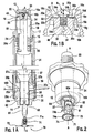
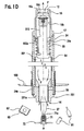
- FIGs 1A, 1B , 1C , 1D , and 2 illustrate preferred embodiments of a dry sprinkler 10.
- the dry sprinkler 10 includes an outer structure assembly 20, outlet frame 25, locator 50, trigger 61, and fluid deflecting structure 70.
- the locator 50 includes a diverter assembly 40 and an inner assembly 501 ( Fig. 1D ).
- the sprinkler 10 can be mounted through a holder or escutcheon 100 as shown in a perspective view of Figure 2 .
- the outer structure assembly 20 defines a passageway 20a that extends along a longitudinal axis A-A between an inlet 12 and an outlet 14.
- the longitudinal axis A-A can be a central axis of the geometric center of the outer structure with a generally constant cross-sectional area over an axial length along the longitudinal axis of the structure.
- the outer structure assembly 20 includes the inlet fitting 16 coupled to a casing tube 24, and an outlet frame 25 coupled to the casing tube 24.
- the casing tube 24 has an inner casing tube surface 24a that cinctures part of the passageway 20a.
- the inner casing tube surface 24a has complementary threads formed at one end that cooperatively engage first coupling threads 18 of the inlet fitting 16.
- the inner casing tube surface 24a has third coupling threads 24d formed proximate the other end of the casing tube 24. The threads 24d terminate at an interior portion 24e of the casing tube 24.
- the casing tube 24 can be coupled to inlet fitting 16 and outlet frame 25 by any suitable technique, such as, for example, thread connections, crimping, bonding, welding, or by a pin and groove.
- a stop surface 17 can be provided as part of the inlet fitting 16.
- the outer inlet fitting surface 16a has fitting threads 16i formed proximate the inlet 12
- the inner inlet fitting surface 16b has first coupling threads formed distal to the threads 16i.
- the fitting threads are used for coupling the dry sprinkler to the piping network
- the inlet fitting 16 has an inlet entrance surface 16c.
- the inlet fitting 16a can be provided with at least one of 3 ⁇ 4 inch, 1 inch, 1.25 inch NPT and 7-1 ISO (Metric) threads 16i formed thereon.
- the inlet fitting 16 has an outer inlet fitting surface 16a and an inner inlet fitting surface 16b.
- the surface 16a cinctures part of the passageway 20a to define an entrance surface 16c and inlet sealing surface 16d.
- the entrance surface 16c can include a convex profile that forms a compound curved surface intersecting a generally planar surface of the inlet sealing surface 16d.
- the inlet fitting 16 can have various different internal surface configurations proximate the entrance surface 16c, however, any suitable configuration may be employed.
- a radiused entrance surface 16c intersects the sealing surface 16d, and the entrance surface 16c can be a surface disposed about the longitudinal axis that has, in a cross-sectional view, a curved profile converging towards the longitudinal axis A-A.
- entrance surface 16c can be a frustoconical surface disposed about the longitudinal axis that has, in a cross-sectional view, a linear profile converging towards the longitudinal axis A-A.
- the sealing surface 16d intersects a surface 16e diverging, and preferably about 60 degrees, to the longitudinal axis A-A.
- the surface 16e intersects a surface 16b extending generally parallel to the longitudinal axis A-A.
- the generally parallel surface 16b intersects a diverging surface 16g, which intersects a surface 16h generally parallel to the longitudinal axis A-A.
- the inlet fitting 16 is provided with a radially projecting boss portion 17.
- the boss portion 17 provides a stop that limits relative threaded engagement between, for example, the inlet fitting 16 and the piping network, the inlet fitting 16 and the casing tube 24, or the outlet frame 25 and the casing tube 24.
- the inlet fitting 16 is provided with screw threads so that the inlet fitting 16 can be coupled to the casing tube 24 via the threaded portion 18.
- the inlet fitting 16 and the casing tube 24 can be formed as a unitary member such that thread portion 18 is not utilized.
- the casing tube 24 can extend as a single tube from the inlet 12 to the outlet 14.
- threaded connection to secure the inlet to the casing can also be utilized such as other mechanical coupling techniques, which can include crimping or bonding.
- other mechanical coupling techniques which can include crimping or bonding.
- either of the respective inner and outer surfaces of the inlet fitting 16, casing tube 24, and outlet frame 25 may be threaded so long as the mating part is cooperatively threaded on the opposite surface, i.e., threads on an inner surface cooperate with threads on an outer surface.
- the locator 50 can include a solid member of a predetermined cross-section such that fluid flows through an inner assembly 501.
- the locator 50 preferably, is disposed within the tubular outer structure assembly 20, which includes the casing tube 24.
- the cross-sectional profiles of the inner and outer surfaces of a tube may be different.
- the locator 50 is coupled to the inner assembly 501, which includes a fluid tube 54, a guide tube 56, and the trigger 61.
- the locator 50 is coupled to the fluid tube 54, and the fluid tube 54 is coupled to the guide tube 56, and the guide tube 56 is coupled to the trigger seat 62 of the trigger 61.
- the locator 50 can locate the diverter assembly 40 with respect to the longitudinal axis A-A.
- the locator 50 has a first yoke support end 51a contacting the diverter assembly 40 and a second yoke support end 51b coupled to the fluid tube 54.
- the locator 50 may optionally include a biasing member that in a preferred embodiment includes an assist spring 55 to assist movement of the locator 50 from its unactuated position ( Fig. 1A ) to an actuated position ( Fig. 1D ).
- the locator 50 has a central axis Y extending generally coincident with the longitudinal axis A-A.
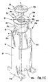
- Locator 50 has two main portions 511 and 512 symmetric about the central axis Y. Each of the main portions has a first end and a second end 51a and 51b.
- a connecting portion 502a connects the main portions 511 and 512 between a first end 51 a and a second end 51 b of each of the main portions 511 and 512.
- the main portions 511 and 512 are each provided with an opening 51c extending along an axis P-P transversely intersecting the yoke axis Y.
- the diverter assembly 40 is fixed to the connector 33 so that the diverter assembly 40 is not free to translate with respect to the locator 50.
- the connecting portion 502a can be a single arcuate member connecting the main portions 511 and 512 on one side of the axis Y to form an elongate member having an arcuate channel extending between the ends of the main portions 511 and 512.
- Locator 50 has some freedom of movement relative to the fluid tube 54 as long as the fluid flow F through the inlet forms a generally symmetric flow path about the locator 50.
- the diverter assembly 40 can be fixed to the locator 50 by a rivet, bolt and nut, screw, two pins, a protrusion cooperating with a recess, or any suitable arrangement that prevents the diverter assembly 40 from rotating with respect to the locator 50 and also allows for compression of the metallic annulus 32 against the sealing surface 16d in a closed position of the dry sprinkler 10.
- locator 50 Due to the alignment of the diverter assembly 40 with the sealing surface 16d of the inlet fitting 16 in the closed position ( Fig. 1A ), locator 50 is generally coaxial with the longitudinal axis A-A in the closed position. Due to the assist spring 55 acting against the asymmetric connecting portion 502a, locator 50 translates along the longitudinal axis A-A in the open position of the dry sprinkler ( Fig. 1D ) such that the outer circumference 32d of the metallic annulus 32 separates from the sealing surface 16d and circumscribes the longitudinal axis A-A to permit a flow of fluid around the shield 30 in a generally symmetric flow path through the passageway 20a.
- outlet frame can be used with the dry sprinklers of the preferred embodiments. Any suitable outlet frame, however, may be used so long as the outlet frame positions a fluid deflecting structure proximate the outlet of the dry sprinkler.
- a preferred outlet frame 25 is shown in Figure 1A .
- Another preferred outlet frame 251 is shown in Figure 1D .
- the outlet frame 25 has an outer outlet frame surface 25a and an inner outlet frame surface 25b, which surfaces cincture part of the passageway 20a.
- the outer outlet frame surface 25a can be provided with coupling threads formed proximate one end of the outlet frame 25 that cooperatively engage coupling threads of the structure 20.
- the outlet frame 25 has an opening 31 so that an annular member, such as a trigger seat 62, can be mounted therein.
- the other end of the outlet frame 25 can include at least one frame arm 27 that is coupled to the fluid deflecting structure 70.
- the outlet frame 25 and frame arms 27 are formed as a unitary member.
- the outlet frame 25, frame aims 27, and fluid deflecting structure 70 can be made from rough or fine casting, and, if desired, machined.
- the thermal trigger 61 is disposed proximate to the outlet 14 of the sprinkler 10.
- the trigger 61 is a frangible bulb that is interposed between a trigger seat 62 and the fluid deflecting structure 70.
- the trigger 61 itself can be a solder link, or any other suitable heat responsive arrangement instead of a frangible bulb.
- the heat responsive trigger may be any suitable arrangement of components that reacts to the appropriate condition(s) by actuating the dry sprinkler.
- the trigger 61 operates to: (1) maintain the inner tubular assembly proximate the first position over the first range of temperatures between about minus 51 degrees Celsius (minus 60 degrees Fahrenheit) to about just below a temperature rating of the trigger; and (2) permit the inner tubular assembly to move along the longitudinal axis to the second position over a second range of temperatures at or greater than the temperature rating of the trigger.
- the temperature rating can be a suitable temperature such as, for example, about 57, 68, 79, 93 or 141 degrees Celsius (134, 155, 175, 200, or 286 degrees Fahrenheit) and plus-or-minus ( ⁇ ) 20% of each of the stated values.
- the trigger seat 62 can be an annular member with a nub portion formed at one end of the trigger seat 62.
- the trigger seat 62 may also include a drain port 63.
- the nub portion has an interior cavity configured to receive a terminal end of the frangible bulb 61.
- the trigger seat 62 has a biasing spring 64 located in a groove 62a.
- the spring 64 is connected to the frame arms 27 of the fluid deflecting structure 70.
- a spacer (not shown) can be located between the second guide tube portion 58 and the trigger seat 62.
- the longitudinal thickness of the spacer would be selected to increase the travel of the locator 50 as it moves from the first position to the second position. In particular, the longitudinal thickness of the spacer would be selected to establish a predetermined travel of the locator 50 before the second end 57b of the first guide tube portion 57 comes to rest on the outlet frame 25.
- the fluid deflecting structure 70 may include an adjustment screw 71 and a planar surface 74 coupled to the frame arms 27 of the outlet frame 25.
- the adjustment screw 71 is provided with external threads 73 that can be used to adjust an axial spacing between the trigger seat 62 and the frangible glass bulb 61.
- the adjustment screw 71 also has a screw seat portion 71 a that engages the frangible bulb 61.
- the adjustment screw 71 and the planar surface member 74a have been described as separate parts, they can be formed as a unitary member.
- a generally planar surface member 74 can be coupled to the adjustment screw 71.
- the planar surface member 74 can be provided with a plurality of tines 74a and a plurality of slots, which are disposed in a predetermined periodic pattern about the longitudinal axis A-A so as to deflect the fluid flow F to form an appropriate spray pattern.
- a planar surface 74 other configurations could be employed to provide the desired fluid deflection pattern.
- the member 74 includes a plurality of tines 74a disposed equiangularly about the longitudinal axis A-A that cooperates with deflecting arms 74b formed on the frame arm 27 to deflect fluid over a desired coverage area.
- the dry sprinkler 10 can extend for a predetermined length L from, for example, a ceiling, a wall, or a floor of an enclosed area.
- the length L can be any value, and preferably, between two to fifty inches depending on the application of the sprinkler 10.
- the diverter assembly 40 includes a shield 30, a metallic annulus 32 and a mounting portion 34.
- the shield 30 includes a first face 30a and a second face 30b disposed about a central axis X-X.
- the central axis X-X preferably defines an axis of the diverter assembly 40, and more particularly, an axis of the first face 30a.
- the first face 30a of the shield 30 extends continuously between the central axis X-X and an outer perimeter of the shield.
- the first face 30a forms an air gap with the inlet surface 16c and preferably forms an air gap with both the inlet surface 16c and the metallic annulus 32.
- the first face 30a has circumference of about 12.7 mm (0.5 inches) with respect to the central axis X-X, the first face 30 defining a generally conic surface that extends at an included angle ⁇ of about 30 degrees with respect to the second face 30b with a tip portion of the conic surface having a radius of curvature R1 of about 3.2 mm (0.125 inches) with respect to the central axis X-X, where the tip portion is located at a distance "h" of about 3.2 mm (1/8 inches) from the second face 30b.
- the diverter assembly 40 also includes a resilient metallic annulus 32.
- the metallic annulus 32 includes a first metallic surface 32a and a second metallic surface 32b spaced apart between an inner circumference 32c to an outer circumference 32d with respect to the central axis X-X.
- the metallic annulus 32 is member that, in its uncompressed state, may have a frustoconical configuration with a base of the frustum facing the inlet, and in a compressed state, has a generally planar configuration with respect to its central axis X-X.
- the metallic annulus 32 can be formed by a suitable resilient material that provides for an appropriate axial spring force as the diverter changes from a compressed to an uncompressed state.
- the resilient material for the diverter can be, for example, stainless steel, beryllium, nickel or combinations thereof.
- a coating may be provided on the diverter such as, for example, synthetic rubber, Teflon, or nylon.
- the metallic annulus 32 can be disposed on the mounting portion 34 so that a third face 34a of the mounting portion 34 confronts the second metallic surface 32b of the metallic annulus 32.
- the third face 34a includes a boss portion 34b that supports the inner circumference 32c of the metallic annulus 32.
- the third face 34a also includes an extension portion 34c that extends between the inner circumference 32c of the metallic annulus 32 and the second face 30b of the shield 30.
- the resilient material is a beryllium and nickel alloy categorized as UNS N03360, 1 ⁇ 2 hard.
- the first face 30a and second face 30b of the shield 30 is preferably provided by a unitary member having a threaded shank portion 30c of about 0.2 inches in length along the central axis X-X that can be used to connect the first and second faces 30a, 30b to the mounting aperture 34d of the mounting portion 34.
- the second face 30b has a first cross-sectional area A1 orthogonal to the central axis X-X less than a second cross-sectional area A2 of the metallic annulus 32 as projected orthogonally with respect to the central axis X-X.
- the third face 34a of the mounting portion 34 has a third cross-sectional area A3 orthogonally with respect to the central axis X-X preferably the same as the first cross-sectional area A1.
- the mounting portion 34 can be coupled to the locator 51 via a connector 33 fixed to both the mounting portion 34 and an opening Sic of the locator 51.
- the mounting portion 34 is fixed to the locator 51 with a suitable connector, such as, for example, a rivet or threaded screw so that the mounting portion 34 is not rotatable about the connector 33.
- a start pressure i.e., an initial pressure present at the inlet when the dry sprinkler is actuated, can be at various start pressures.
- the start pressure is at least 1.37896.105 Pa (20 pounds per square inch (psig) ) , and, more particular, greater than 6,89480 ⁇ 10 5 Pa (100 psig ) .
- the dry sprinkler 10 has a rated discharge coefficient, or rated K- factor, that is at least 80.8 (5.6 in US units), and, can be 115.4, 161.6, 202.0, 242.4, 207.8 or 368.0 (8.0, 11.2, 14.0, 16.8, 14.4 or 25.5 in US units).
- K- factor rated discharge coefficient
- any suitable value for the K-factor could be provided for the dry sprinkler of the preferred embodiments.
- the discharge coefficient or K-factor is quantified as a flow of fluid, preferably fluid, from the outlet 14 of the outer structure assembly 20, e.g., in liters per minute (in gallons per minute), (GPM), divided by the square root of the pressure of the fluid fed into the outer structure assembly 20, e.g., in 10 5 Pa (pounds per square inch gauge (psig)).
- the rated K-factor, or rated discharge coefficient is a mean value.
- the rated K-factors are expressed in standard sizes, which have an acceptable range, which is approximately five percent or less deviation from the standard value over the range of pressures.
- a "rated" K-factor of 161.6 (11.2 in US units) encompasses all measured K-factors between 158.7 (11.0 in US units) and 116.0 (11.5 in US units).
- the K-factors of the preferred embodiment may decrease as the sprinkler length L increases. For example, when L is 1.22m (48 inchest the K- factor of the dry sprinkler 10 can be reduced from 161.6 (11.2 in US units) to approximately 147.2 (10.2 in US units).
- the K-factor allows for an approximation of flow rate to be expected from the outlet of a sprinkler based on the square root of the pressure of fluid fed into the inlet of the sprinkler.
- the dry sprinkler of each of the preferred embodiments has a rated K-factor of at least 80.8 (5.6 in US units).
- each dry sprinkler has an arrangement of components that allows for an actual minimum flow rate in liter per minute (gallons per minute (GPM) in US units) through the outlet as a product of the rated K- factor and the square root of the pressure in 10 5 Pa (pounds per square inch gauge (psig) in US units) of the fluid fed into an inlet of the dry sprinkler of each preferred embodiment.
- the preferred embodiment has an actual minimum flow rate from the outlet 14 of approximately equal to 95% of the magnitude of a rated K-factor times the square root of the pressure of the flow of fluid fed into the inlet of each embodiment.
- the diverter assembly 40 can include a suitable shape that presents as small a frontal area and as small a coefficient of drag as suitable when the diverter assembly 40 is translated to the open position.
- a frontal surface area is provided by the first face 30a of the shield 30 and the metallic annulus 32.
- a flow of fluid through the inlet is diverted into a generally symmetrical flow path about the shield 30 when the locator is translated to a second position ( Fig. 1 D) in the structure 24.
- the flow of fluid is diverted by the shield 30 when the locator is translated to a second position so that a majority of the flow does not impinge upon the metallic surface 32a of the annulus 32 during operation of the dry sprinkler where the pressure of the fluid flow F is between 0 and 12.06583 ⁇ 10 5 Pa (175 psig) and the flow rate is about 95% of the rated K-factor times the square root of the pressure of the fluid fed to the inlet.
- the cross-sectional area A1 of the shield is less than the largest cross-sectional area A2 of the diverter assembly 40 and the height "h" of the shield and the angle of inclination 0 with respect to an orthogonal axis relative to axis X-X are configured so that the majority of flow does not impinge upon operational flow of fluid through the dry sprinkler.
- the first face 30a is configured with the height "h” so that the face 30a does not extend past the outer periphery of inlet surface 16c.
- the diverter assembly 40 is supported by contacting the mounting portion 34 against a portion of the locator 50 so that the metallic annulus 32 of the diverter assembly 40, in an unactuated position of the dry sprinkler 10, engages a sealing surface 16d of the inlet fitting 16.
- the first metallic surface 32a of the metallic annulus 32 of the diverter assembly 40 is preferably compressed against the sealing surface 16d such that the central axis X-X of the metallic surface 32a is generally coaxial with the longitudinal axis A-A and the shield 30 acts to reduce the formation of an ice dam on the inlet surface 16c.
- the metallic annulus 32 When the dry sprinkler 10 is actuated by activation of the trigger 61 so that the metallic annulus 32 is biased from the sealing surface 16d, the metallic annulus 32 forms a generally truncated cone with its central axis X-X generally coaxial with the longitudinal axis A-A.
- the first face 30a or bias member 55 can be made of a copper, bronze, galvanized carbon steel, carbon steel, or stainless steel material.
- the trigger 61 In operation, when the trigger 61 is actuated, e.g., by shattering where the trigger is frangible bulb, the trigger 61 separates from the dry sprinkler 10. The separation of the trigger 61 removes the support for the locator 50 against the resilient spring force of the metallic annulus 32 or the mass of the fluid at the inlet 12. Consequently, the metallic annulus 32 separates from the sealing surface 16d as the diverter assembly 40 translates along with the locator 50 and inner assembly 501. The axial force provided by the metallic annulus 32 or the spring 55 assists in separating the diverter assembly 40 from the inlet fitting 16. Thereafter, fluid or a suitable fire-fighting fluid is allowed to flow through the inlet 12.
- the diverter assembly 40 Due to the configuration of the diverter assembly 40, including the first face 30a, fluid flow F through the inlet 12 to the outlet 14 forms a generally symmetric flow path about the axis A-A through a portion of the passageway 20a.
- the diverter assembly 40 and the locator 50 provide the means for establishing a generally symmetric fluid flow F path about the longitudinal axis A-A through the outlet at a flow rate of at least 95 percent of the rated K-factor multiplied by the square root of the pressure of the fluid flow F fed to the inlet 12 in bar (equals 10 5 Pa) (pounds per square inch gauge in US units).
- the deflector 72 distributes the fluid flow F over a protection area below the sprinkler 10.
- the means do not include any sealing member whose sealing member is positioned, in its entirety, offset or asymmetric to the longitudinal axis A-A in the passageway 20a in either in the closed or opened position of the locator 50.
Landscapes
- Health & Medical Sciences (AREA)
- Public Health (AREA)
- Business, Economics & Management (AREA)
- Emergency Management (AREA)
- Fire-Extinguishing By Fire Departments, And Fire-Extinguishing Equipment And Control Thereof (AREA)
- Investigating Materials By The Use Of Optical Means Adapted For Particular Applications (AREA)
- Nozzles (AREA)
- Gasket Seals (AREA)
Abstract
Description
- Automatic sprinkler systems are some of the most widely used devices for fire protection. These systems have sprinklers that are activated once the ambient temperature in an environment, such as a room or building exceeds a predetermined value. Once activated, the sprinklers distribute fire-extinguishing fluid, preferably water, in the room or building. A sprinkler system is considered effective if it extinguishes or prevents growth of a fire. Failures of such systems may occur when the system has been rendered inoperative during building alternation or disuse, or the occupancy hazard has been increased beyond initial system capability. Examples of known automatic sprinklers include:
U.S. Patent No. 6,367,599 which is directed to an automatic flush sprinkler sidewall sprinkler assembly, andU.S. Patent No. 6,554,077 which is directed to quick response adjustable automatic sprinkler arrangements. - The fluid supply for a sprinkler system may be separate from that used by a fire department. An underground main for the sprinkler system enters the building to supply a riser. Connected at the riser are valves, meters, and, preferably, an alarm to sound when fluid flow within the system exceeds a predetermined minimum. At the top of a vertical riser, a horizontally disposed array of pipes extends throughout the fire compartment in the building. Other risers may feed distribution networks to systems in adjacent fire compartments. Compartmentalization can divide a large building horizontally, on a single floor, and, vertically, floor to floor. Thus, several sprinkler systems may serve one building.
- In the piping distribution network, branch lines carry the sprinklers. A sprinkler may extend up from a branch line, placing the sprinkler relatively close to the ceiling, or a sprinkler can be pendant below the branch line. For use with concealed piping, a flush-mounted pendant sprinkler may extend only slightly below the ceiling.
- Fluid for fighting a fire can be provided to the sprinklers in various configurations. In a wet-pipe system, for buildings having heated spaces for piping branch lines, all the system pipes contain water for immediate release through any sprinkler that is activated. In a dry-pipe system, which may include pipes, risers, and feed mains, disposed in unheated open areas, cold rooms, passageways, or other areas exposed to freezing temperatures, such as unheated buildings in freezing climates or cold-storage rooms, branch lines and other distribution pipes may contain a dry gas (air or nitrogen) under pressure. This pressure of gas holds closed a dry pipe valve at the riser. When heat from a fire activates a sprinkler, the gas escapes and the dry-pipe valve trips, water enters branch lines, and fire fighting begins as the sprinkler distributes the fluid.
- Dry sprinklers are used where the sprinklers may be exposed to freezing temperatures. A dry sprinkler may include a threaded inlet containing a closure assembly, some length of tubing connected to the threaded inlet, and a fluid deflecting structure located at the other end of the tubing. There may also be a mechanism that connects the thermally responsive component to the closure assembly.
The threaded inlet is preferably secured to a branch line. Depending on the particular installation, the branch line may be filled with fluid (wet pipe system) or be filled with a gas (dry pipe system). In either installation, the medium within the branch line is generally excluded from the tubing of the dry sprinkler via the closure assembly until activation of the thermally responsive component. In some dry sprinklers, when the thermally responsive component releases, the closure assembly or portions of the mechanism may be expelled from the tubing of the dry sprinkler by fluid pressure and gravity. In other types of dry sprinklers, the closure assembly is pivotally mounted to a movable mechanism that is a tube structure, and the closure assembly is designed to pivot on a pin pivot axis transverse to the longitudinal axis of the dry sprinkler, while the tube structure is maintained within the tubing of the dry sprinkler. - Examples of known dry sprinklers include:
U.S. Patent No. 5,188,185 , which is directed to a dry sprinkler:U.S. Patent No. 1,903,150 , which is directed to a sprinkler head for a dry pipe fire extinguishing system andU.S. Patent No. 5,775,431 , which is directed to dry sprinkler arrangements. In known dry sprinklers, a sealing plug has been provided as a component of a closure assembly to seal the inlet of the dry sprinkler. The sealing plug includes a metallic annulus that has a face disposed about a central axis between an inner perimeter and outer perimeter. When the dry sprinkler is in an unactuated condition, the central axis of the sealing plug is generally parallel and aligned with the longitudinal axis of the tubing so that the metallic annulus is elastically deformed. Upon actuation of the dry sprinkler, the metallic annulus provides a force to assist in movement of the closure assembly along the longitudinal axis of the tubing. - In order to utilize the sealing plug, an arrangement of components is provided within the known dry sprinklers. This arrangement of components positions the sealing plug within the passageway defined by the tube structure to prohibit and allow fluid flow through the dry sprinkler. The sealing plug is positioned at the inlet to provide a seal of the inlet, and within the passageway to permit flow through the dry sprinkler. When the sealing plug is positioned to occlude the inlet, the arrangement of components orients the central axis of the sealing plug generally parallel to and aligned with the longitudinal axis. When the sealing plug is positioned within the passage to allow flow through the outlet of the dry sprinkler, the arrangement of components translates the sealing plug along the passageway.
- Although the known dry sprinklers have employed a sealing plug with an elastically deformable metallic annulus to translate the closure assembly within the passageway, the arrangement of components, including the sealing plug, has been found to be inadequate for the performance of the dry sprinkler. Specifically, the inventors has discovered that the known arrangements of components apparently fail to provide a flow rate in which the known sprinklers were rated for in a fire protection system.
- The present invention provides a dry sprinkler for a fire protection system. The present invention allows a dry sprinkler to operate over a range of start pressures for a rated K-factor. The present invention provides an operative dry sprinkler by maintaining a positive seal while the dry sprinkler is in a standby, i.e., unactuated mode, and by permitting a flow of at least 95% of the rated flow as determined by the product of the rated K-factor of the sprinkler and the square root of the gauge pressure of the fluid fed to an inlet in 105 Pa (bar) (pounds per square inch gauge in US units) when a heat responsive trigger actuates the dry sprinkler.
- In one aspect of the present invention, a dry sprinkler is provided having an unactuated mode and an actuated mode comprising:
- a structure defining a passageway extending along a longitutinal axis (A-A) between an inlet and an outlet, the structure, the structure having a rated K-factor defining an expected flow of fluid in litres (gallons) per minute from the outlet divided by the square root of the gauge pressure of the flow of fluid fed into the inlet of the passageway in 105 pascal (pounds per square inch gauge);
- a fluid deflecting structure proximate the outlet at first distance in the unactuated mode and at a second distance in the actuated mode, the first and second distances being equal; and
- means for establishing a generally symmetric fluid flow path about the longitudinal axis (A-A) through the outlet at a flow rate of at least 95 percent of the rated K-factor multiplied by the square root of the pressure of the fluid flow fed into the inlet in 105 pascal (pounds per square inch gauge), the means including:
- a locator having a tubular member with a first end, a second end and a channel extending between the first and second ends coaxially with the longitudinal axis (A-A) to define a fluid passage, the locator being movable along the longitudinal axis (A-A) between a first position and a second position;
- a diverter assembly supported by the locator for occluding a flow of fluid through the passageway when the locator is in the first positon,; and an arrangement that prevents cliverter assembly from rotating with respect to the locator.
- The accompanying drawings, which are incorporated herein and constitute part of this specification, illustrate exemplary embodiments of the invention, and, together with the general description given above and the detailed description given below, serve to explain the features of the invention,
-
Figures 1A-1D illustrate a preferred embodiment of the dry sprinkler. -
Figure 2 illustrates the dry sprinkler ofFigures 1A-1 D in an installed configuration. - As installed, a sprinkler is coupled to a piping network (not shown), which is supplied with a fire fighting fluid, e.g., fluid from a pressurized supply source. The preferred embodiments include dry sprinklers that are suitable for use such as, for example, with a dry pipe system. (e.g. that is the entire system is exposed to freezing temperatures in an unheated portion of a building) or a wet pipe system {e.g. the sprinkler extends into an unheated portion of a building). Pipe systems may be installed in accordance with the 2002 Edition of the National Fire Protection Association Standard for the Installation of Sprinkler Systems, NFPA 13 (2002 edition).
-
Figures 1A, 1B ,1C ,1D , and2 illustrate preferred embodiments of adry sprinkler 10. Thedry sprinkler 10 includes anouter structure assembly 20,outlet frame 25,locator 50,trigger 61, andfluid deflecting structure 70. Thelocator 50 includes adiverter assembly 40 and an inner assembly 501 (Fig. 1D ). Thesprinkler 10 can be mounted through a holder orescutcheon 100 as shown in a perspective view ofFigure 2 . Theouter structure assembly 20 defines apassageway 20a that extends along a longitudinal axis A-A between aninlet 12 and anoutlet 14. The longitudinal axis A-A can be a central axis of the geometric center of the outer structure with a generally constant cross-sectional area over an axial length along the longitudinal axis of the structure. - The
outer structure assembly 20 includes the inlet fitting 16 coupled to acasing tube 24, and anoutlet frame 25 coupled to thecasing tube 24. Thecasing tube 24 has an innercasing tube surface 24a that cinctures part of thepassageway 20a. According to the preferred embodiment, the innercasing tube surface 24a has complementary threads formed at one end that cooperatively engagefirst coupling threads 18 of the inlet fitting 16. The innercasing tube surface 24a has third coupling threads 24d formed proximate the other end of thecasing tube 24. The threads 24d terminate at aninterior portion 24e of thecasing tube 24. - The
casing tube 24 can be coupled to inlet fitting 16 andoutlet frame 25 by any suitable technique, such as, for example, thread connections, crimping, bonding, welding, or by a pin and groove. Astop surface 17 can be provided as part of the inlet fitting 16.
According to one configuration of the inlet, the outerinlet fitting surface 16a hasfitting threads 16i formed proximate theinlet 12, and the innerinlet fitting surface 16b has first coupling threads formed distal to thethreads 16i. The fitting threads are used for coupling the dry sprinkler to the piping network, and the inlet fitting 16 has aninlet entrance surface 16c. The inlet fitting 16a can be provided with at least one of ¾ inch, 1 inch, 1.25 inch NPT and 7-1 ISO (Metric)threads 16i formed thereon. - The inlet fitting 16 has an outer
inlet fitting surface 16a and an innerinlet fitting surface 16b. Thesurface 16a cinctures part of thepassageway 20a to define anentrance surface 16c andinlet sealing surface 16d. In one preferred embodiment, theentrance surface 16c can include a convex profile that forms a compound curved surface intersecting a generally planar surface of theinlet sealing surface 16d. The inlet fitting 16 can have various different internal surface configurations proximate theentrance surface 16c, however, any suitable configuration may be employed. In the preferred embodiment ofFigure 1A , aradiused entrance surface 16c intersects the sealingsurface 16d, and theentrance surface 16c can be a surface disposed about the longitudinal axis that has, in a cross-sectional view, a curved profile converging towards the longitudinal axis A-A. - Alternatively,
entrance surface 16c can be a frustoconical surface disposed about the longitudinal axis that has, in a cross-sectional view, a linear profile converging towards the longitudinal axis A-A. The sealingsurface 16d intersects asurface 16e diverging, and preferably about 60 degrees, to the longitudinal axis A-A. Thesurface 16e intersects asurface 16b extending generally parallel to the longitudinal axis A-A.
The generallyparallel surface 16b intersects a divergingsurface 16g, which intersects asurface 16h generally parallel to the longitudinal axis A-A. - According to the preferred embodiments, the inlet fitting 16 is provided with a radially projecting
boss portion 17. Theboss portion 17 provides a stop that limits relative threaded engagement between, for example, the inlet fitting 16 and the piping network, the inlet fitting 16 and thecasing tube 24, or theoutlet frame 25 and thecasing tube 24. - According to a preferred embodiment, the inlet fitting 16 is provided with screw threads so that the inlet fitting 16 can be coupled to the
casing tube 24 via the threadedportion 18. Alternatively, the inlet fitting 16 and thecasing tube 24 can be formed as a unitary member such thatthread portion 18 is not utilized. For example, thecasing tube 24 can extend as a single tube from theinlet 12 to theoutlet 14. - Alternatives to the threaded connection to secure the inlet to the casing can also be utilized such as other mechanical coupling techniques, which can include crimping or bonding. Additionally, either of the respective inner and outer surfaces of the inlet fitting 16,
casing tube 24, andoutlet frame 25 may be threaded so long as the mating part is cooperatively threaded on the opposite surface, i.e., threads on an inner surface cooperate with threads on an outer surface. - The
locator 50 can include a solid member of a predetermined cross-section such that fluid flows through aninner assembly 501. Thelocator 50, preferably, is disposed within the tubularouter structure assembly 20, which includes thecasing tube 24. The terms "tube" or "tubular," as they are used herein, denote an elongate member with a suitable cross-sectional shape transverse to the longitudinal axis A-A, such as, for example, circular, oval, or polygonal. Moreover, the cross-sectional profiles of the inner and outer surfaces of a tube may be different. - The
locator 50 is coupled to theinner assembly 501, which includes afluid tube 54, aguide tube 56, and thetrigger 61. In the non-actuated configuration, thelocator 50 is coupled to thefluid tube 54, and thefluid tube 54 is coupled to theguide tube 56, and theguide tube 56 is coupled to thetrigger seat 62 of thetrigger 61. Thelocator 50 can locate thediverter assembly 40 with respect to the longitudinal axis A-A. Thelocator 50 has a firstyoke support end 51a contacting thediverter assembly 40 and a secondyoke support end 51b coupled to thefluid tube 54. Thelocator 50 may optionally include a biasing member that in a preferred embodiment includes anassist spring 55 to assist movement of thelocator 50 from its unactuated position (Fig. 1A ) to an actuated position (Fig. 1D ). - Referring to
Figure 1C , thelocator 50 has a central axis Y extending generally coincident with the longitudinal axis A-A.Locator 50 has twomain portions second end portion 502a connects themain portions first end 51 a and asecond end 51 b of each of themain portions main portions opening 51c extending along an axis P-P transversely intersecting the yoke axis Y. Thediverter assembly 40 is fixed to theconnector 33 so that thediverter assembly 40 is not free to translate with respect to thelocator 50. - As shown in
Figure 1C , the connectingportion 502a can be a single arcuate member connecting themain portions main portions Locator 50 has some freedom of movement relative to thefluid tube 54 as long as the fluid flow F through the inlet forms a generally symmetric flow path about thelocator 50. - In lieu of the
connector 33 of the preferred embodiment, thediverter assembly 40 can be fixed to thelocator 50 by a rivet, bolt and nut, screw, two pins, a protrusion cooperating with a recess, or any suitable arrangement that prevents thediverter assembly 40 from rotating with respect to thelocator 50 and also allows for compression of themetallic annulus 32 against the sealingsurface 16d in a closed position of thedry sprinkler 10. - Due to the alignment of the
diverter assembly 40 with the sealingsurface 16d of the inlet fitting 16 in the closed position (Fig. 1A ),locator 50 is generally coaxial with the longitudinal axis A-A in the closed position. Due to theassist spring 55 acting against theasymmetric connecting portion 502a,locator 50 translates along the longitudinal axis A-A in the open position of the dry sprinkler (Fig. 1D ) such that theouter circumference 32d of themetallic annulus 32 separates from the sealingsurface 16d and circumscribes the longitudinal axis A-A to permit a flow of fluid around theshield 30 in a generally symmetric flow path through thepassageway 20a. - Various configurations of the outlet frame can be used with the dry sprinklers of the preferred embodiments. Any suitable outlet frame, however, may be used so long as the outlet frame positions a fluid deflecting structure proximate the outlet of the dry sprinkler. A
preferred outlet frame 25 is shown inFigure 1A . Anotherpreferred outlet frame 251 is shown inFigure 1D . - The
outlet frame 25 has an outeroutlet frame surface 25a and an inneroutlet frame surface 25b, which surfaces cincture part of thepassageway 20a. The outeroutlet frame surface 25a can be provided with coupling threads formed proximate one end of theoutlet frame 25 that cooperatively engage coupling threads of thestructure 20. Theoutlet frame 25 has anopening 31 so that an annular member, such as atrigger seat 62, can be mounted therein. - The other end of the
outlet frame 25 can include at least oneframe arm 27 that is coupled to thefluid deflecting structure 70. Preferably, theoutlet frame 25 and framearms 27 are formed as a unitary member. Theoutlet frame 25, frame aims 27, andfluid deflecting structure 70 can be made from rough or fine casting, and, if desired, machined. - The
thermal trigger 61 is disposed proximate to theoutlet 14 of thesprinkler 10. Preferably, thetrigger 61 is a frangible bulb that is interposed between atrigger seat 62 and thefluid deflecting structure 70. Alternatively, thetrigger 61 itself can be a solder link, or any other suitable heat responsive arrangement instead of a frangible bulb.
Instead of a frangible bulb or a solder link, the heat responsive trigger may be any suitable arrangement of components that reacts to the appropriate condition(s) by actuating the dry sprinkler. - The
trigger 61 operates to: (1) maintain the inner tubular assembly proximate the first position over the first range of temperatures between about minus 51 degrees Celsius (minus 60 degrees Fahrenheit) to about just below a temperature rating of the trigger; and (2) permit the inner tubular assembly to move along the longitudinal axis to the second position over a second range of temperatures at or greater than the temperature rating of the trigger. The temperature rating can be a suitable temperature such as, for example, about 57, 68, 79, 93 or 141 degrees Celsius (134, 155, 175, 200, or 286 degrees Fahrenheit) and plus-or-minus (±) 20% of each of the stated values. - The
trigger seat 62 can be an annular member with a nub portion formed at one end of thetrigger seat 62. Thetrigger seat 62 may also include adrain port 63. The nub portion has an interior cavity configured to receive a terminal end of thefrangible bulb 61. Thetrigger seat 62 has a biasingspring 64 located in agroove 62a. Thespring 64 is connected to theframe arms 27 of thefluid deflecting structure 70. A spacer (not shown) can be located between the secondguide tube portion 58 and thetrigger seat 62. The longitudinal thickness of the spacer would be selected to increase the travel of thelocator 50 as it moves from the first position to the second position. In particular, the longitudinal thickness of the spacer would be selected to establish a predetermined travel of thelocator 50 before thesecond end 57b of the firstguide tube portion 57 comes to rest on theoutlet frame 25. - The
fluid deflecting structure 70 may include anadjustment screw 71 and aplanar surface 74 coupled to theframe arms 27 of theoutlet frame 25. Theadjustment screw 71 is provided with external threads 73 that can be used to adjust an axial spacing between thetrigger seat 62 and thefrangible glass bulb 61. Theadjustment screw 71 also has ascrew seat portion 71 a that engages thefrangible bulb 61. Although theadjustment screw 71 and theplanar surface member 74a have been described as separate parts, they can be formed as a unitary member. - A generally
planar surface member 74 can be coupled to theadjustment screw 71.
Theplanar surface member 74 can be provided with a plurality oftines 74a and a plurality of slots, which are disposed in a predetermined periodic pattern about the longitudinal axis A-A so as to deflect the fluid flow F to form an appropriate spray pattern. Instead of aplanar surface 74, other configurations could be employed to provide the desired fluid deflection pattern. Preferably, themember 74 includes a plurality oftines 74a disposed equiangularly about the longitudinal axis A-A that cooperates with deflectingarms 74b formed on theframe arm 27 to deflect fluid over a desired coverage area. - The
dry sprinkler 10 can extend for a predetermined length L from, for example, a ceiling, a wall, or a floor of an enclosed area. The length L can be any value, and preferably, between two to fifty inches depending on the application of thesprinkler 10. - To form a seal with the sealing
surface 16d of the inlet fitting 16, adiverter assembly 40 can be used. Thediverter assembly 40 includes ashield 30, ametallic annulus 32 and a mountingportion 34. Theshield 30 includes afirst face 30a and a second face 30b disposed about a central axis X-X. The central axis X-X preferably defines an axis of thediverter assembly 40, and more particularly, an axis of thefirst face 30a. Thefirst face 30a of theshield 30 extends continuously between the central axis X-X and an outer perimeter of the shield. Thefirst face 30a forms an air gap with theinlet surface 16c and preferably forms an air gap with both theinlet surface 16c and themetallic annulus 32. Preferably, thefirst face 30a has circumference of about 12.7 mm (0.5 inches) with respect to the central axis X-X, thefirst face 30 defining a generally conic surface that extends at an included angle θ of about 30 degrees with respect to the second face 30b with a tip portion of the conic surface having a radius of curvature R1 of about 3.2 mm (0.125 inches) with respect to the central axis X-X, where the tip portion is located at a distance "h" of about 3.2 mm (1/8 inches) from the second face 30b. Thediverter assembly 40 also includes a resilientmetallic annulus 32. Themetallic annulus 32 includes a firstmetallic surface 32a and a secondmetallic surface 32b spaced apart between aninner circumference 32c to anouter circumference 32d with respect to the central axis X-X. Preferably, themetallic annulus 32 is member that, in its uncompressed state, may have a frustoconical configuration with a base of the frustum facing the inlet, and in a compressed state, has a generally planar configuration with respect to its central axis X-X. Themetallic annulus 32 can be formed by a suitable resilient material that provides for an appropriate axial spring force as the diverter changes from a compressed to an uncompressed state. The resilient material for the diverter can be, for example, stainless steel, beryllium, nickel or combinations thereof. A coating may be provided on the diverter such as, for example, synthetic rubber, Teflon, or nylon. Themetallic annulus 32 can be disposed on the mountingportion 34 so that athird face 34a of the mountingportion 34 confronts the secondmetallic surface 32b of themetallic annulus 32. Thethird face 34a includes aboss portion 34b that supports theinner circumference 32c of themetallic annulus 32. Thethird face 34a also includes an extension portion 34c that extends between theinner circumference 32c of themetallic annulus 32 and the second face 30b of theshield 30. Preferably, the resilient material is a beryllium and nickel alloy categorized as UNS N03360, ½ hard. - The
first face 30a and second face 30b of theshield 30 is preferably provided by a unitary member having a threadedshank portion 30c of about 0.2 inches in length along the central axis X-X that can be used to connect the first andsecond faces 30a, 30b to the mountingaperture 34d of the mountingportion 34. The second face 30b has a first cross-sectional area A1 orthogonal to the central axis X-X less than a second cross-sectional area A2 of themetallic annulus 32 as projected orthogonally with respect to the central axis X-X. Thethird face 34a of the mountingportion 34 has a third cross-sectional area A3 orthogonally with respect to the central axis X-X preferably the same as the first cross-sectional area A1. - The mounting
portion 34 can be coupled to thelocator 51 via aconnector 33 fixed to both the mountingportion 34 and an opening Sic of thelocator 51. Preferably, the mountingportion 34 is fixed to thelocator 51 with a suitable connector, such as, for example, a rivet or threaded screw so that the mountingportion 34 is not rotatable about theconnector 33. - The
metallic annulus 32 of thediverter assembly 40, in conjunction with the sealingsurface 16d of the inlet fitting 16, can form a seal against fluid pressure proximate the sealingsurface 16d at any start pressure from approximately zero to approximately psig so that thethird face 34a of the mountingportion 34 facing theoutlet 14 is generally free of fluid. In particular, a start pressure, i.e., an initial pressure present at the inlet when the dry sprinkler is actuated, can be at various start pressures. Preferably, the start pressure is at least 1.37896.105 Pa (20 pounds per square inch (psig)), and, more particular, greater than 6,89480·105 Pa (100 psig). - Preferably, the
dry sprinkler 10 has a rated discharge coefficient, or rated K- factor, that is at least 80.8 (5.6 in US units), and, can be 115.4, 161.6, 202.0, 242.4, 207.8 or 368.0 (8.0, 11.2, 14.0, 16.8, 14.4 or 25.5 in US units). However, any suitable value for the K-factor could be provided for the dry sprinkler of the preferred embodiments. As used herein, the discharge coefficient or K-factor is quantified as a flow of fluid, preferably fluid, from theoutlet 14 of theouter structure assembly 20, e.g., in liters per minute (in gallons per minute), (GPM), divided by the square root of the pressure of the fluid fed into theouter structure assembly 20, e.g., in 105 Pa (pounds per square inch gauge (psig)). The rated K-factor, or rated discharge coefficient is a mean value.
The rated K-factors are expressed in standard sizes, which have an acceptable range, which is approximately five percent or less deviation from the standard value over the range of pressures. For example, a "rated" K-factor of 161.6 (11.2 in US units) encompasses all measured K-factors between 158.7 (11.0 in US units) and 116.0 (11.5 in US units). The K-factors of the preferred embodiment may decrease as the sprinkler length L increases. For example, when L is 1.22m (48 inchest the K- factor of thedry sprinkler 10 can be reduced from 161.6 (11.2 in US units) to approximately 147.2 (10.2 in US units). - The K-factor allows for an approximation of flow rate to be expected from the outlet of a sprinkler based on the square root of the pressure of fluid fed into the inlet of the sprinkler. In relation to the preferred embodiments, the dry sprinkler of each of the preferred embodiments has a rated K-factor of at least 80.8 (5.6 in US units). Based on the rated K- factor of the dry sprinkler of the preferred embodiments, each dry sprinkler has an arrangement of components that allows for an actual minimum flow rate in liter per minute (gallons per minute (GPM) in US units) through the outlet as a product of the rated K- factor and the square root of the pressure in 105 Pa (pounds per square inch gauge (psig) in US units) of the fluid fed into an inlet of the dry sprinkler of each preferred embodiment. Specifically, the preferred embodiment has an actual minimum flow rate from the
outlet 14 of approximately equal to 95% of the magnitude of a rated K-factor times the square root of the pressure of the flow of fluid fed into the inlet of each embodiment. - To minimize the restriction upon the fluid flowing through
outer structure assembly 20 of thedry sprinkler 10, thediverter assembly 40 can include a suitable shape that presents as small a frontal area and as small a coefficient of drag as suitable when thediverter assembly 40 is translated to the open position. In particular, a frontal surface area is provided by thefirst face 30a of theshield 30 and themetallic annulus 32. Preferably, by virtue of the shape of thefirst face 30a, a flow of fluid through the inlet is diverted into a generally symmetrical flow path about theshield 30 when the locator is translated to a second position (Fig. 1 D) in thestructure 24. And more preferably, the flow of fluid is diverted by theshield 30 when the locator is translated to a second position so that a majority of the flow does not impinge upon themetallic surface 32a of theannulus 32 during operation of the dry sprinkler where the pressure of the fluid flow F is between 0 and 12.06583·105 Pa (175 psig) and the flow rate is about 95% of the rated K-factor times the square root of the pressure of the fluid fed to the inlet. In particular, the cross-sectional area A1 of the shield is less than the largest cross-sectional area A2 of thediverter assembly 40 and the height "h" of the shield and the angle of inclination 0 with respect to an orthogonal axis relative to axis X-X are configured so that the majority of flow does not impinge upon operational flow of fluid through the dry sprinkler. In the preferred embodiments, thefirst face 30a is configured with the height "h" so that theface 30a does not extend past the outer periphery ofinlet surface 16c. - The
diverter assembly 40 is supported by contacting the mountingportion 34 against a portion of thelocator 50 so that themetallic annulus 32 of thediverter assembly 40, in an unactuated position of thedry sprinkler 10, engages a sealingsurface 16d of the inlet fitting 16. During engagement with the sealingsurface 16d, the firstmetallic surface 32a of themetallic annulus 32 of thediverter assembly 40 is preferably compressed against the sealingsurface 16d such that the central axis X-X of themetallic surface 32a is generally coaxial with the longitudinal axis A-A and theshield 30 acts to reduce the formation of an ice dam on theinlet surface 16c. When thedry sprinkler 10 is actuated by activation of thetrigger 61 so that themetallic annulus 32 is biased from the sealingsurface 16d, themetallic annulus 32 forms a generally truncated cone with its central axis X-X generally coaxial with the longitudinal axis A-A. Preferably, each of the inlet fitting, means for establishing a generally symmetric flow, thefirst face 30a orbias member 55 can be made of a copper, bronze, galvanized carbon steel, carbon steel, or stainless steel material. - In operation, when the
trigger 61 is actuated, e.g., by shattering where the trigger is frangible bulb, thetrigger 61 separates from thedry sprinkler 10. The separation of thetrigger 61 removes the support for thelocator 50 against the resilient spring force of themetallic annulus 32 or the mass of the fluid at theinlet 12. Consequently, themetallic annulus 32 separates from the sealingsurface 16d as thediverter assembly 40 translates along with thelocator 50 andinner assembly 501. The axial force provided by themetallic annulus 32 or thespring 55 assists in separating thediverter assembly 40 from the inlet fitting 16. Thereafter, fluid or a suitable fire-fighting fluid is allowed to flow through theinlet 12. Due to the configuration of thediverter assembly 40, including thefirst face 30a, fluid flow F through theinlet 12 to theoutlet 14 forms a generally symmetric flow path about the axis A-A through a portion of thepassageway 20a.
Hence, thediverter assembly 40 and thelocator 50 provide the means for establishing a generally symmetric fluid flow F path about the longitudinal axis A-A through the outlet at a flow rate of at least 95 percent of the rated K-factor multiplied by the square root of the pressure of the fluid flow F fed to theinlet 12 in bar (equals 105 Pa) (pounds per square inch gauge in US units). Thereafter, thedeflector 72 distributes the fluid flow F over a protection area below thesprinkler 10. It should be noted that the means, however, do not include any sealing member whose sealing member is positioned, in its entirety, offset or asymmetric to the longitudinal axis A-A in thepassageway 20a in either in the closed or opened position of thelocator 50. - While the present invention has been disclosed with reference to certain preferred embodiments, numerous modifications, alterations, and changes to the described embodiments are possible without departing from the sphere and scope of the present invention, as defined in the appended claims. Accordingly, it is intended that the present invention not be limited to the described embodiments, but that it have the full scope defined by the language of the following claims, and equivalents thereof.
Claims (27)
- A dry sprinkler (10) having an unactuated mode and an actuated mode comprising:a structure (20) defining a passageway extending along a longitudinal axis (A-A) between an inlet (12) and an outlet (14), the structure having a rated K-factor defining an expected flow of fluid in litres (gallons) per minute from the outlet (14) divided by the square root of the gauge pressure of the flow of fluid fed into the inlet (12) of the passageway in 105 pascal (pounds per square inch gauge);a fluid deflecting structure (70) proximate the outlet (14) at first distance in the unactuated mode and at a second distance in the actuated mode, the first and second distances being equal; andmeans for establishing a generally symmetric fluid flow path about the longitudinal axis (A-A) through the outlet (14) at a flow rate of at least 95 percent of the rated K-factor multiplied by the square root of the gauge pressure of the fluid flow fed into the inlet (12) in 105 pascal (pounds per square inch gauge), the means including:a locator (50) having a tubular member with a first end, a second end and a channel extending between the first and second ends coaxially with the longitudinal axis (A-A) to define a fluid passage, the locator (50) being movable along the longitudinal axis (A-A) between a first position and a second position;a diverter assembly (40) supported by the locator (50) for occluding a flow of fluid through the passageway when the locator (50) is in the first position; andan arrangement that prevents the diverter assembly (40) from rotating with respect to the locator (50).
- The dry sprinkler (10) of claim 1, wherein the structure (20) comprises a tubular member disposed about the longitudinal axis (A-A).
- The dry sprinkler (10) of claim 2, wherein the locator (50) comprises a yoke having wall portions symmetric to the longitudinal axis (A-A).
- The dry sprinkler (10) of claim 3, wherein the diverter assembly (40) further includes:a metallic annulus (32) having first and second metallic surfaces (32a, 32b) spaced apart along the longitudinal axis (A-A) between an inner circumference and outer circumference with respect to the longitudinal axis (A-A), the metallic annulus (32) occluding the flow of fluid through the passageway when the locator (50) is proximate the first position;a shield (30) having a first face (30a) exposed to the inlet (12), a second face (30b) confronting the first metallic surface (32a) to define a gap therebetween; andthe mounting portion (34) supporting the metallic annulus (32) and the shield (30), the mounting portion (34) further having a third face (34a) confronting the second metallic surface (32b).
- The dry sprinkler (10) of claim 4, wherein the first face (30a) of the shield (30) comprises a generally conical surface disposed about an axis extending through the shield (30), the first face (30a) including a first cross-sectional area disposed about the axis.
- The dry sprinkler, (10) of claim 5, wherein the second face (30b) of the shield (30) comprises a generally planar surface disposed about the axis, the second face (30b) including a second cross-sectional area disposed about the axis.
- The dry sprinkler (10) of claim 6, wherein the axis comprises an axis of the shield (30) generally coincident with the longitudinal axis (A-A).
- The dry sprinkler (10) of claim 4, wherein the third face (34a) of the mounting portion (34) is spaced apart from the first and second surfaces of the shield (30) and confronting the second metallic surface (32b) of the metallic annulus (32), wherein the shield (30) defines a first cross-sectional area and the metallic annulus (32) defines a second cross-sectional area, the third face of the mounting portion (34) including a third cross-sectional area orthogonal about the longitudinal axis (A-A).
- The dry sprinkler (10) of claim 8, wherein the third face (34a) comprises a portion that extends across the gap between the second face (30b) and the metallic annulus (32).
- The dry sprinkler (10) of claim 1, wherein the locator (50) comprises an elongate member disposed within the structure.
- The dry sprinkler (10) of claim 10, wherein the locator (50) is coupled to the diverter assembly(40) by a pin (33) disposed along an axis generally orthogonal to the longitudinal axis (A-A).
- The dry sprinkler (10) of claim 1, wherein the inlet (12) comprises a sealing surface (16d) disposed about the longitudinal axis (A-A) proximate the inlet (12).
- The dry sprinkler (10) of claim 12, wherein the locator (50) has a first non-actuated position and a second actuated position, and the first and second metallic surfaces (32a, 32b) define a plane generally orthogonal to the longitudinal axis (A-A), the first metallic surface (32a) being contiguous to the sealing surface (16d) of the inlet (12) in the first position of the locator (50).
- The dry sprinkler (10) of claim 13, wherein the first and second metallic surfaces (32a, 32b) circumscribe the longitudinal axis (A-A) to define a generally truncated cone with its base generally orthogonal to the longitudinal axis (A-A) in the second position of the locator (50).
- The dry sprinkler (10) of claim 14, wherein the inlet (12) comprises a generally cylindrical outer surface having one of 19,05 mm (3/4 inch), 25,4 mm (1 inch), 31,75 mm (1.25 inch) NPT and 7-1 ISO threads formed thereon.
- The dry sprinkler (10) of claim 15, wherein the inlet (12) further comprises a curved surface (16c) exposed to the inlet (12), the curved surface (16c) being connected to a generally planar sealing surface (16d), the generally planar sealing surface (16d) being coupled to a truncated conical surface (16e) facing the longitudinal axis(A-A) adjacent the generally planar sealing surface (16d), the truncated conical surface (16e) extending at an angle of about sixty degrees with respect to the longitudinal axis (A-A).
- The dry sprinkler (10) of claim 15, wherein the inlet (12) comprises an entrance surface (16c) having a first end and a second end disposed along and surrounding the longitudinal axis (A-A) with a generally radiused surface of curvature and a seat surface (16d) adjacent the second end of the entrance surface (16c) that provides a seal in conjunction with the metallic annulus (32).
- The dry sprinkler (10) of claim 17, wherein the entrance surface (16c) comprises a convex surface surrounding the longitudinal axis (A-A) and the seat surface (16d) comprises a planar annulus surface surrounding the longitudinal axis (A-A).
- The dry sprinkler (10) of claim 18, wherein the inlet (12) further comprises an oblique surface (16e) adjacent the planar annulus surface.
- The dry sprinkler (10) of claim 4, wherein the first face (30a) comprises a generally conical surface disposed about an axis extending through the first face (30a), the first face (30a) including a first cross-sectional area disposed about the axis, the first metallic surface (32a) having an orthogonal projection defining a second cross-sectional area disposed about the axis, the third face (34a) of the mounting portion (34) including a generally planar surface disposed about the axis defining a third cross-sectional area disposed about the axis, and each of the first and third cross-sectional areas having a magnitude less than the second cross-sectional area.
- The dry sprinkler (10) of claim 20, wherein the mounting portion (34) comprises a portion that extends across the gap between the second face (30b) and the first metallic surface (32a).
- The dry sprinkler (10) of claim 21, wherein the structure comprises a tubular member disposed about the longitudinal axis (A-A) and the locator (50) comprises a yoke having wall portions (511, 512) symmetric to the longitudinal axis (A-A).
- The dry sprinkler (10) of claim 22, wherein the inlet (12) comprises a sealing surface (16d) disposed about the longitudinal axis (A-A) proximate the inlet (12).
- The dry sprinkler (10) of claim 23, wherein the first and second metallic surfaces (32a, 32b) comprise a planar surface generally orthogonal to the longitudinal axis (A-A), the first metallic surface (32a) being contiguous to the sealing surface (16d) in the first position of the locator (50).
- The dry sprinkler (10) of claim 24, wherein the first and second metallic surfaces (32a, 32b) circumscribe the longitudinal axis (A-A) to define a cone with its base generally orthogonal to the longitudinal axis (A-A) in the second position of the locator (50).
- The dry sprinkler (10) of claim 1, wherein the inlet (12) includes:a planar sealing surface (16d) disposed about and perpendicular to the longitudinal axis (A-A);an entrance surface (16c) disposed about the longitudinal axis (A-A), the entrance surface (16c) converging toward the longitudinal axis (A-A) so as to define a curved profile intersecting the sealing surface (16d), anda diverging surface (16e) disposed about the longitudinal axis (A-A), the diverging surface intersecting the sealing surface (16d) and defining a profile diverging from the longitudinal axis (A-A) at an angle.
- The dry sprinkler (10) of claim 26, wherein the diverter assembly (40) further includes:a metallic annulus (32) having first and second metallic surfaces (32a, 32b) spaced apart along the longitudinal axis (A-A) between an inner circumference and outer circumference with respect to the longitudinal axis (A-A), a portion of the first metallic surface (32a) engaging the planar sealing surface (16d) of the inlet (12) to occluding the flow of fluid through the passageway when the locator (50) is proximate the first position; anda shield (30) defining a central axis (X-X) coaxial with the longitudinal axis (A-A), the shield (30) connected to the mounting portion (34) such that the shield (30) forms a gap with the first metallic surface (32a) of the metallic annulus (32) and the central axis (X-X) of the shield (30) remains coaxial with the longitudinal axis (A-A) when the locator (50) moves from the first position to the second position.
Applications Claiming Priority (2)
| Application Number | Priority Date | Filing Date | Title |
|---|---|---|---|
| US11/000,129 US7559376B2 (en) | 2004-12-01 | 2004-12-01 | Dry sprinkler with a diverter seal assembly |
| PCT/US2005/042994 WO2006060341A2 (en) | 2004-12-01 | 2005-11-30 | Dry sprinkler with a diverter seal assembly |
Publications (3)
| Publication Number | Publication Date |
|---|---|
| EP1817084A2 EP1817084A2 (en) | 2007-08-15 |
| EP1817084A4 EP1817084A4 (en) | 2007-11-21 |
| EP1817084B1 true EP1817084B1 (en) | 2010-06-02 |
Family
ID=36565603
Family Applications (1)
| Application Number | Title | Priority Date | Filing Date |
|---|---|---|---|
| EP05849632A Expired - Lifetime EP1817084B1 (en) | 2004-12-01 | 2005-11-30 | Dry sprinkler with a diverter seal assembly |
Country Status (8)
| Country | Link |
|---|---|
| US (6) | US7559376B2 (en) |
| EP (1) | EP1817084B1 (en) |
| AT (1) | ATE469682T1 (en) |
| CA (1) | CA2588678C (en) |
| DE (1) | DE602005021682D1 (en) |
| DK (1) | DK1817084T3 (en) |
| ES (1) | ES2346675T3 (en) |
| WO (1) | WO2006060341A2 (en) |
Families Citing this family (28)
| Publication number | Priority date | Publication date | Assignee | Title |
|---|---|---|---|---|
| US7165624B1 (en) * | 1998-05-15 | 2007-01-23 | Grinnell Corporation | Early suppression fast response fire protection sprinkler |
| US6976543B1 (en) | 2000-11-22 | 2005-12-20 | Grinnell Corporation | Low pressure, extended coverage, upright fire protection sprinkler |
| US7516800B1 (en) | 2002-07-19 | 2009-04-14 | Tyco Fire Products Lp | Dry sprinkler |
| US8327946B1 (en) | 2002-07-19 | 2012-12-11 | Tyco Fire Products Lp | Dry sprinkler |
| CA2462636C (en) * | 2004-02-09 | 2010-09-14 | The Viking Corporation | Dry sprinkler assembly |
| US7559376B2 (en) | 2004-12-01 | 2009-07-14 | Tyco Fire Products Lp | Dry sprinkler with a diverter seal assembly |
| US20060289174A1 (en) * | 2005-06-22 | 2006-12-28 | Hong-Zeng Yu | Deluge-like sprinkler fire scheme using high thermal sensitivity and high temperature rating sensing elements |
| US7766252B2 (en) * | 2006-02-15 | 2010-08-03 | The Viking Corporation | Dry sprinkler assembly |
| US20070215362A1 (en) * | 2006-03-20 | 2007-09-20 | Fire Sprinkler System, Inc. | Fire sprinkler system |
| US8162069B2 (en) * | 2006-09-05 | 2012-04-24 | The Reliable Automatic Sprinkler Co., Inc. | Automatic fire protection sprinkler with extended body |
| US9358411B2 (en) | 2011-05-27 | 2016-06-07 | Victaulic Company | Flexible dry sprinkler |
| PH12013502562A1 (en) | 2011-06-28 | 2022-11-23 | Tyco Fire Products Lp | Dry sprinklers with multiple coupling arrangements |
| US9511248B2 (en) | 2011-08-10 | 2016-12-06 | Victaulic Company | Sprinkler system and installation |
| US10549135B2 (en) * | 2012-02-07 | 2020-02-04 | Marioff Corporation Oy | Water mist fire suppression sprinkler with a polymer seal |
| CN104602766A (en) | 2012-04-20 | 2015-05-06 | 泰科消防产品有限合伙公司 | Dry sprinkler assemblies |
| US8887822B2 (en) | 2012-06-01 | 2014-11-18 | Reliable Automatic Sprinkler Co., Inc. | Flexible dry sprinklers |
| FR3002152B1 (en) * | 2013-02-21 | 2015-12-04 | Vactec | DRY CANDLE INTENDED TO BE MOUNTED IN A FIRE PROTECTION PLANT COMPRISING A VACUUM SPRINKLERS NETWORK |
| GB2537414B (en) * | 2015-04-17 | 2019-11-13 | Graviner Ltd Kidde | Pyrotechnic valve |
| CN108136242B (en) | 2015-10-06 | 2021-11-26 | 马里奥夫有限公司 | Suppression unit and method |
| ES3039117T3 (en) | 2015-10-06 | 2025-10-17 | Marioff Corp Oy | Suppression unit, nozzle for suppression unit, and method |
| US11110311B2 (en) | 2017-05-31 | 2021-09-07 | Tyco Fire Products Lp | Antifreeze formulation and sprinkler systems comprising improved antifreezes |
| KR102651259B1 (en) | 2018-08-23 | 2024-03-25 | 빅톨릭 컴패니 | Dry sprinkler assembly |
| WO2021077060A1 (en) * | 2019-10-17 | 2021-04-22 | Minimax Viking Research & Development Gmbh | Dry sprinkler assemblies for fire protection sprinkler systems |
| US11577108B2 (en) | 2019-10-17 | 2023-02-14 | Minimax Viking Research & Development Gmbh | Dry sprinkler assemblies for fire protection sprinkler systems |
| WO2021202525A1 (en) * | 2020-04-01 | 2021-10-07 | Minimax Viking Research & Development Gmbh | Dry fire protection sprinkler assemblies |
| WO2021202543A1 (en) * | 2020-04-01 | 2021-10-07 | Minimax Viking Research & Development Gmbh | Dry fire protection sprinkler and fluid deflection member assemblies |
| US12186608B2 (en) | 2021-04-14 | 2025-01-07 | Tyco Fire Products Lp | Thermal trigger seat for sprinkler system |
| WO2023215165A2 (en) | 2022-05-01 | 2023-11-09 | Minimax Viking Research & Development Gmbh | Dry fire protection sprinkler assemblies and systems |
Family Cites Families (43)
| Publication number | Priority date | Publication date | Assignee | Title |
|---|---|---|---|---|
| US2732018A (en) | 1956-01-24 | Pendent sprinkler head | ||
| US1338469A (en) | 1916-07-24 | 1920-04-27 | Sivert P Waage | Thermally-actuated drain-valve |
| US1903150A (en) | 1932-04-04 | 1933-03-28 | Tyden Emil | Pendant sprinkler system |
| US2155990A (en) | 1938-05-25 | 1939-04-25 | Jr Willis K Hodgman | Pendant sprinkler head |
| US2180258A (en) | 1938-08-09 | 1939-11-14 | Globe Automatic Sprinkler Co | Sprinkler system |
| US2211399A (en) | 1939-03-02 | 1940-08-13 | Seth L Winslow | Sprinkler head |
| US2291813A (en) | 1941-07-24 | 1942-08-04 | Gen Fire Extinguisher Co | Sprinkler system |
| US2291818A (en) | 1941-07-24 | 1942-08-04 | Gen Fire Extinguisher Co | Sprinkler system |
| US2768696A (en) | 1953-05-01 | 1956-10-30 | Grinnell Corp | Sprinkler systems |
| US2871953A (en) | 1954-12-06 | 1959-02-03 | Grinnell Corp | Pendent sprinkler |
| US3007528A (en) | 1959-07-17 | 1961-11-07 | Star Sprinkler Corp | Dry pendant sprinklers |
| US3061015A (en) | 1960-01-11 | 1962-10-30 | Hodgman Mfg Co Inc | Dry pendent sprinkler head |
| US3067823A (en) | 1960-07-01 | 1962-12-11 | Frederick J Kavanagh | Automatic sprinkler |
| US3080000A (en) | 1961-07-19 | 1963-03-05 | Star Sprinkler Corp | Dry pendant sprinklers |
| US3135331A (en) | 1962-09-24 | 1964-06-02 | Floyd J Lee | Dry adapter for fire-extinguishing sprinkler systems |
| US3401751A (en) | 1966-04-22 | 1968-09-17 | Standard Fire Prot Equipment C | Dry pipes sprinkler system |
| US3584689A (en) | 1969-06-26 | 1971-06-15 | Norris Industries | Dry-type sprinkler |
| US3924687A (en) | 1974-02-20 | 1975-12-09 | Viking Corp | Valve and sprinkler head for automatic fire extinguishing systems |
| US4007878A (en) | 1976-08-19 | 1977-02-15 | Central Sprinkler Corporation | Adjustable dry pendant sprinkler head assembly |
| US4091872A (en) | 1977-02-07 | 1978-05-30 | A-T-O Inc. | Adjustable dry pendent sprinkler |
| GB1564662A (en) | 1977-06-15 | 1980-04-10 | Mather & Platt Ltd | Sprinkler arrangements |
| US4220208A (en) | 1977-11-21 | 1980-09-02 | Hays Heating & Plumbing Company | Dry pipe fire extinguishing sprinkler system |
| US4237982A (en) | 1978-05-01 | 1980-12-09 | The Reliable Automatic Sprinkler Co., Inc. | Adjustable dry sprinkler having a latching mechanism controlled by a sleeve |
| US4228858A (en) | 1978-05-01 | 1980-10-21 | The Reliable Automatic Sprinkler Co. | Dry sprinkler with non-load-transmitting sealing arrangement |
| US4258795A (en) | 1979-03-08 | 1981-03-31 | Central Sprinkler Corporation | On-off sprinkler head having an offset drive motor |
| US4417626A (en) | 1982-07-12 | 1983-11-29 | Interfit, Inc. | Adjustable pendent sprinkler assembly |
| US4830117A (en) * | 1987-12-24 | 1989-05-16 | Fire Sprinkler Specialties, Inc. | Shut-off device for an automatic sprinkler |
| US5228520A (en) | 1988-12-22 | 1993-07-20 | Holger Gottschalk | Sprinkler system for refrigerated spaces |
| US5188185A (en) | 1991-06-19 | 1993-02-23 | Grinnell Corporation | Dry sprinkler |
| DE4122665A1 (en) | 1991-07-09 | 1993-01-14 | Total Feuerschutz Gmbh | SPRINKLER FOR AUTOMATIC FIRE-FIGHTING SYSTEMS |
| US5366022A (en) | 1991-09-30 | 1994-11-22 | Central Sprinkler Corporation | Extended coverage ceiling sprinklers and systems |
| US5775431A (en) | 1996-09-11 | 1998-07-07 | The Reliable Automatic Sprinkler Co., Inc. | Dry sprinkler arrangements |
| US6152236A (en) * | 1998-10-05 | 2000-11-28 | The Viking Corporation | Combined trigger and concealing device for a sprinkler head |
| US6367559B1 (en) * | 1998-12-29 | 2002-04-09 | The Viking Corporation | Double-blade deflector for side wall sprinkler |
| US6962208B2 (en) | 2000-05-17 | 2005-11-08 | The Viking Corporation | Compact pendant sprinkler head |
| US6851482B2 (en) | 2000-11-02 | 2005-02-08 | Kevin Michael Dolan | Sprinkler assembly |
| US6554077B2 (en) * | 2001-04-12 | 2003-04-29 | The Reliable Automatic Sprinkler Co., Inc. | Quick response adjustable automatic sprinkler arrangements |
| US20030075343A1 (en) | 2001-10-22 | 2003-04-24 | National Foam, Inc., D/B/A Kidde Fire Fighting | Dry sprinkler |
| US7516800B1 (en) | 2002-07-19 | 2009-04-14 | Tyco Fire Products Lp | Dry sprinkler |
| CA2462636C (en) * | 2004-02-09 | 2010-09-14 | The Viking Corporation | Dry sprinkler assembly |
| US7275603B2 (en) * | 2004-10-26 | 2007-10-02 | The Reliable Automatic Sprinkler Co., Inc. | Concealed pendent fire protection sprinkler with drop-down deflector |
| US7559376B2 (en) | 2004-12-01 | 2009-07-14 | Tyco Fire Products Lp | Dry sprinkler with a diverter seal assembly |
| US7766252B2 (en) | 2006-02-15 | 2010-08-03 | The Viking Corporation | Dry sprinkler assembly |
-
2004
- 2004-12-01 US US11/000,129 patent/US7559376B2/en not_active Expired - Lifetime
-
2005
- 2005-11-30 WO PCT/US2005/042994 patent/WO2006060341A2/en not_active Ceased
- 2005-11-30 ES ES05849632T patent/ES2346675T3/en not_active Expired - Lifetime
- 2005-11-30 AT AT05849632T patent/ATE469682T1/en not_active IP Right Cessation
- 2005-11-30 DK DK05849632.4T patent/DK1817084T3/en active
- 2005-11-30 CA CA2588678A patent/CA2588678C/en not_active Expired - Lifetime
- 2005-11-30 DE DE602005021682T patent/DE602005021682D1/en not_active Expired - Lifetime
- 2005-11-30 EP EP05849632A patent/EP1817084B1/en not_active Expired - Lifetime
-
2009
- 2009-05-06 US US12/436,290 patent/US8225881B2/en not_active Expired - Lifetime
-
2012
- 2012-06-21 US US13/529,033 patent/US8826998B2/en not_active Expired - Lifetime
-
2013
- 2013-03-11 US US13/793,392 patent/US20130186652A1/en not_active Abandoned
-
2016
- 2016-11-10 US US15/348,340 patent/US9737742B2/en not_active Expired - Lifetime
- 2016-11-10 US US15/348,421 patent/US9744390B2/en not_active Expired - Lifetime
Also Published As
| Publication number | Publication date |
|---|---|
| EP1817084A2 (en) | 2007-08-15 |
| US8225881B2 (en) | 2012-07-24 |
| ATE469682T1 (en) | 2010-06-15 |
| US20170056697A1 (en) | 2017-03-02 |
| DK1817084T3 (en) | 2010-09-27 |
| US20170056696A1 (en) | 2017-03-02 |
| CA2588678C (en) | 2015-01-06 |
| CA2588678A1 (en) | 2006-06-08 |
| US20130186652A1 (en) | 2013-07-25 |
| US9744390B2 (en) | 2017-08-29 |
| US20090211772A1 (en) | 2009-08-27 |
| EP1817084A4 (en) | 2007-11-21 |
| US7559376B2 (en) | 2009-07-14 |
| WO2006060341A3 (en) | 2007-03-01 |
| ES2346675T3 (en) | 2010-10-19 |
| US9737742B2 (en) | 2017-08-22 |
| US20130153247A1 (en) | 2013-06-20 |
| WO2006060341A2 (en) | 2006-06-08 |
| US8826998B2 (en) | 2014-09-09 |
| US20060113093A1 (en) | 2006-06-01 |
| DE602005021682D1 (en) | 2010-07-15 |
Similar Documents
| Publication | Publication Date | Title |
|---|---|---|
| US9737742B2 (en) | Dry sprinkler with a diverter seal assembly | |
| US11925826B2 (en) | Dry sprinkler assemblies | |
| US10195473B1 (en) | Dry sprinkler | |
| EP2012881B1 (en) | Extended coverage horizontal sidewall sprinkler | |
| US20250195930A1 (en) | Dry sprinkler | |
| US20050178564A1 (en) | Fast response sprinkler assembly for a fire extinguishing system | |
| AU2012275317B2 (en) | Dry sprinklers with multiple coupling arrangements | |
| NZ618903B2 (en) | Dry sprinklers with multiple coupling arrangements |
Legal Events
| Date | Code | Title | Description |
|---|---|---|---|
| PUAI | Public reference made under article 153(3) epc to a published international application that has entered the european phase |
Free format text: ORIGINAL CODE: 0009012 |
|
| 17P | Request for examination filed |
Effective date: 20070524 |
|
| AK | Designated contracting states |
Kind code of ref document: A2 Designated state(s): AT BE BG CH CY CZ DE DK EE ES FI FR GB GR HU IE IS IT LI LT LU LV MC NL PL PT RO SE SI SK TR |
|
| AX | Request for extension of the european patent |
Extension state: AL BA HR MK YU |
|
| A4 | Supplementary search report drawn up and despatched |
Effective date: 20071023 |
|
| DAX | Request for extension of the european patent (deleted) | ||
| 17Q | First examination report despatched |
Effective date: 20081006 |
|
| RAP1 | Party data changed (applicant data changed or rights of an application transferred) |
Owner name: TYCO FIRE PRODUCTS LP |
|
| GRAP | Despatch of communication of intention to grant a patent |
Free format text: ORIGINAL CODE: EPIDOSNIGR1 |
|
| GRAS | Grant fee paid |
Free format text: ORIGINAL CODE: EPIDOSNIGR3 |
|
| GRAA | (expected) grant |
Free format text: ORIGINAL CODE: 0009210 |
|
| AK | Designated contracting states |
Kind code of ref document: B1 Designated state(s): AT BE BG CH CY CZ DE DK EE ES FI FR GB GR HU IE IS IT LI LT LU LV MC NL PL PT RO SE SI SK TR |
|
| REG | Reference to a national code |
Ref country code: GB Ref legal event code: FG4D |
|
| REG | Reference to a national code |
Ref country code: CH Ref legal event code: EP |
|
| REG | Reference to a national code |
Ref country code: IE Ref legal event code: FG4D |
|
| REF | Corresponds to: |
Ref document number: 602005021682 Country of ref document: DE Date of ref document: 20100715 Kind code of ref document: P |
|
| REG | Reference to a national code |
Ref country code: NL Ref legal event code: T3 |
|
| REG | Reference to a national code |
Ref country code: SE Ref legal event code: TRGR |
|
| REG | Reference to a national code |
Ref country code: DK Ref legal event code: T3 |
|
| REG | Reference to a national code |
Ref country code: ES Ref legal event code: FG2A Ref document number: 2346675 Country of ref document: ES Kind code of ref document: T3 |
|
| PG25 | Lapsed in a contracting state [announced via postgrant information from national office to epo] |
Ref country code: LT Free format text: LAPSE BECAUSE OF FAILURE TO SUBMIT A TRANSLATION OF THE DESCRIPTION OR TO PAY THE FEE WITHIN THE PRESCRIBED TIME-LIMIT Effective date: 20100602 |
|
| LTIE | Lt: invalidation of european patent or patent extension |
Effective date: 20100602 |
|
| PG25 | Lapsed in a contracting state [announced via postgrant information from national office to epo] |
Ref country code: AT Free format text: LAPSE BECAUSE OF FAILURE TO SUBMIT A TRANSLATION OF THE DESCRIPTION OR TO PAY THE FEE WITHIN THE PRESCRIBED TIME-LIMIT Effective date: 20100602 Ref country code: SI Free format text: LAPSE BECAUSE OF FAILURE TO SUBMIT A TRANSLATION OF THE DESCRIPTION OR TO PAY THE FEE WITHIN THE PRESCRIBED TIME-LIMIT Effective date: 20100602 Ref country code: LV Free format text: LAPSE BECAUSE OF FAILURE TO SUBMIT A TRANSLATION OF THE DESCRIPTION OR TO PAY THE FEE WITHIN THE PRESCRIBED TIME-LIMIT Effective date: 20100602 |
|
| PG25 | Lapsed in a contracting state [announced via postgrant information from national office to epo] |
Ref country code: GR Free format text: LAPSE BECAUSE OF FAILURE TO SUBMIT A TRANSLATION OF THE DESCRIPTION OR TO PAY THE FEE WITHIN THE PRESCRIBED TIME-LIMIT Effective date: 20100903 Ref country code: PL Free format text: LAPSE BECAUSE OF FAILURE TO SUBMIT A TRANSLATION OF THE DESCRIPTION OR TO PAY THE FEE WITHIN THE PRESCRIBED TIME-LIMIT Effective date: 20100602 Ref country code: CY Free format text: LAPSE BECAUSE OF FAILURE TO SUBMIT A TRANSLATION OF THE DESCRIPTION OR TO PAY THE FEE WITHIN THE PRESCRIBED TIME-LIMIT Effective date: 20100602 |
|
| PG25 | Lapsed in a contracting state [announced via postgrant information from national office to epo] |
Ref country code: EE Free format text: LAPSE BECAUSE OF FAILURE TO SUBMIT A TRANSLATION OF THE DESCRIPTION OR TO PAY THE FEE WITHIN THE PRESCRIBED TIME-LIMIT Effective date: 20100602 |
|
| PG25 | Lapsed in a contracting state [announced via postgrant information from national office to epo] |
Ref country code: PT Free format text: LAPSE BECAUSE OF FAILURE TO SUBMIT A TRANSLATION OF THE DESCRIPTION OR TO PAY THE FEE WITHIN THE PRESCRIBED TIME-LIMIT Effective date: 20101004 Ref country code: IS Free format text: LAPSE BECAUSE OF FAILURE TO SUBMIT A TRANSLATION OF THE DESCRIPTION OR TO PAY THE FEE WITHIN THE PRESCRIBED TIME-LIMIT Effective date: 20101002 Ref country code: SK Free format text: LAPSE BECAUSE OF FAILURE TO SUBMIT A TRANSLATION OF THE DESCRIPTION OR TO PAY THE FEE WITHIN THE PRESCRIBED TIME-LIMIT Effective date: 20100602 Ref country code: CZ Free format text: LAPSE BECAUSE OF FAILURE TO SUBMIT A TRANSLATION OF THE DESCRIPTION OR TO PAY THE FEE WITHIN THE PRESCRIBED TIME-LIMIT Effective date: 20100602 Ref country code: RO Free format text: LAPSE BECAUSE OF FAILURE TO SUBMIT A TRANSLATION OF THE DESCRIPTION OR TO PAY THE FEE WITHIN THE PRESCRIBED TIME-LIMIT Effective date: 20100602 |
|
| PLBE | No opposition filed within time limit |
Free format text: ORIGINAL CODE: 0009261 |
|
| STAA | Information on the status of an ep patent application or granted ep patent |
Free format text: STATUS: NO OPPOSITION FILED WITHIN TIME LIMIT |
|
| 26N | No opposition filed |
Effective date: 20110303 |
|
| REG | Reference to a national code |
Ref country code: DE Ref legal event code: R097 Ref document number: 602005021682 Country of ref document: DE Effective date: 20110302 |
|
| PG25 | Lapsed in a contracting state [announced via postgrant information from national office to epo] |
Ref country code: MC Free format text: LAPSE BECAUSE OF NON-PAYMENT OF DUE FEES Effective date: 20101130 |
|
| REG | Reference to a national code |
Ref country code: CH Ref legal event code: PL |
|
| PG25 | Lapsed in a contracting state [announced via postgrant information from national office to epo] |
Ref country code: CH Free format text: LAPSE BECAUSE OF NON-PAYMENT OF DUE FEES Effective date: 20101130 Ref country code: LI Free format text: LAPSE BECAUSE OF NON-PAYMENT OF DUE FEES Effective date: 20101130 |
|
| PG25 | Lapsed in a contracting state [announced via postgrant information from national office to epo] |
Ref country code: IE Free format text: LAPSE BECAUSE OF NON-PAYMENT OF DUE FEES Effective date: 20101130 |
|
| PG25 | Lapsed in a contracting state [announced via postgrant information from national office to epo] |
Ref country code: HU Free format text: LAPSE BECAUSE OF FAILURE TO SUBMIT A TRANSLATION OF THE DESCRIPTION OR TO PAY THE FEE WITHIN THE PRESCRIBED TIME-LIMIT Effective date: 20101203 Ref country code: LU Free format text: LAPSE BECAUSE OF NON-PAYMENT OF DUE FEES Effective date: 20101130 Ref country code: BG Free format text: LAPSE BECAUSE OF FAILURE TO SUBMIT A TRANSLATION OF THE DESCRIPTION OR TO PAY THE FEE WITHIN THE PRESCRIBED TIME-LIMIT Effective date: 20100602 |
|
| PG25 | Lapsed in a contracting state [announced via postgrant information from national office to epo] |
Ref country code: TR Free format text: LAPSE BECAUSE OF FAILURE TO SUBMIT A TRANSLATION OF THE DESCRIPTION OR TO PAY THE FEE WITHIN THE PRESCRIBED TIME-LIMIT Effective date: 20100602 |
|
| PG25 | Lapsed in a contracting state [announced via postgrant information from national office to epo] |
Ref country code: BG Free format text: LAPSE BECAUSE OF FAILURE TO SUBMIT A TRANSLATION OF THE DESCRIPTION OR TO PAY THE FEE WITHIN THE PRESCRIBED TIME-LIMIT Effective date: 20100902 |
|
| REG | Reference to a national code |
Ref country code: FR Ref legal event code: PLFP Year of fee payment: 11 |
|
| REG | Reference to a national code |
Ref country code: FR Ref legal event code: PLFP Year of fee payment: 12 |
|
| REG | Reference to a national code |
Ref country code: FR Ref legal event code: PLFP Year of fee payment: 13 |
|
| PGFP | Annual fee paid to national office [announced via postgrant information from national office to epo] |
Ref country code: DK Payment date: 20201125 Year of fee payment: 16 |
|
| PGFP | Annual fee paid to national office [announced via postgrant information from national office to epo] |
Ref country code: BE Payment date: 20201127 Year of fee payment: 16 |
|
| REG | Reference to a national code |
Ref country code: DK Ref legal event code: EBP Effective date: 20211130 |
|
| PG25 | Lapsed in a contracting state [announced via postgrant information from national office to epo] |
Ref country code: BE Free format text: LAPSE BECAUSE OF NON-PAYMENT OF DUE FEES Effective date: 20211130 |
|
| REG | Reference to a national code |
Ref country code: BE Ref legal event code: MM Effective date: 20211130 |
|
| PG25 | Lapsed in a contracting state [announced via postgrant information from national office to epo] |
Ref country code: DK Free format text: LAPSE BECAUSE OF NON-PAYMENT OF DUE FEES Effective date: 20211130 |
|
| PGFP | Annual fee paid to national office [announced via postgrant information from national office to epo] |
Ref country code: NL Payment date: 20231124 Year of fee payment: 19 |
|
| PGFP | Annual fee paid to national office [announced via postgrant information from national office to epo] |
Ref country code: ES Payment date: 20231218 Year of fee payment: 19 |
|
| PGFP | Annual fee paid to national office [announced via postgrant information from national office to epo] |
Ref country code: FI Payment date: 20231124 Year of fee payment: 19 |
|
| PGFP | Annual fee paid to national office [announced via postgrant information from national office to epo] |
Ref country code: DE Payment date: 20241128 Year of fee payment: 20 |
|
| PGFP | Annual fee paid to national office [announced via postgrant information from national office to epo] |
Ref country code: GB Payment date: 20241126 Year of fee payment: 20 |
|
| PGFP | Annual fee paid to national office [announced via postgrant information from national office to epo] |
Ref country code: FR Payment date: 20241126 Year of fee payment: 20 |
|
| PGFP | Annual fee paid to national office [announced via postgrant information from national office to epo] |
Ref country code: IT Payment date: 20241125 Year of fee payment: 20 |
|
| PGFP | Annual fee paid to national office [announced via postgrant information from national office to epo] |
Ref country code: SE Payment date: 20241224 Year of fee payment: 20 |
|
| PG25 | Lapsed in a contracting state [announced via postgrant information from national office to epo] |
Ref country code: FI Free format text: LAPSE BECAUSE OF NON-PAYMENT OF DUE FEES Effective date: 20241130 |
|
| REG | Reference to a national code |
Ref country code: NL Ref legal event code: MM Effective date: 20241201 |
|
| PG25 | Lapsed in a contracting state [announced via postgrant information from national office to epo] |
Ref country code: NL Free format text: LAPSE BECAUSE OF NON-PAYMENT OF DUE FEES Effective date: 20241201 |
|
| REG | Reference to a national code |
Ref country code: DE Ref legal event code: R071 Ref document number: 602005021682 Country of ref document: DE |
|
| REG | Reference to a national code |
Ref country code: GB Ref legal event code: PE20 Expiry date: 20251129 |
|
| REG | Reference to a national code |
Ref country code: ES Ref legal event code: FD2A Effective date: 20260107 |
|
| PG25 | Lapsed in a contracting state [announced via postgrant information from national office to epo] |
Ref country code: ES Free format text: LAPSE BECAUSE OF NON-PAYMENT OF DUE FEES Effective date: 20241201 |