EP1816779A2 - Interoperability verification for implementation according to communication standard - Google Patents
Interoperability verification for implementation according to communication standard Download PDFInfo
- Publication number
- EP1816779A2 EP1816779A2 EP07001627A EP07001627A EP1816779A2 EP 1816779 A2 EP1816779 A2 EP 1816779A2 EP 07001627 A EP07001627 A EP 07001627A EP 07001627 A EP07001627 A EP 07001627A EP 1816779 A2 EP1816779 A2 EP 1816779A2
- Authority
- EP
- European Patent Office
- Prior art keywords
- pilot
- symbol
- implementation
- seed
- communication stream
- Prior art date
- Legal status (The legal status is an assumption and is not a legal conclusion. Google has not performed a legal analysis and makes no representation as to the accuracy of the status listed.)
- Withdrawn
Links
Images

Classifications
-
- H—ELECTRICITY
- H04—ELECTRIC COMMUNICATION TECHNIQUE
- H04L—TRANSMISSION OF DIGITAL INFORMATION, e.g. TELEGRAPHIC COMMUNICATION
- H04L1/00—Arrangements for detecting or preventing errors in the information received
- H04L1/24—Testing correct operation
- H04L1/242—Testing correct operation by comparing a transmitted test signal with a locally generated replica
- H04L1/244—Testing correct operation by comparing a transmitted test signal with a locally generated replica test sequence generators
-
- H—ELECTRICITY
- H04—ELECTRIC COMMUNICATION TECHNIQUE
- H04W—WIRELESS COMMUNICATION NETWORKS
- H04W24/00—Supervisory, monitoring or testing arrangements
-
- H—ELECTRICITY
- H04—ELECTRIC COMMUNICATION TECHNIQUE
- H04L—TRANSMISSION OF DIGITAL INFORMATION, e.g. TELEGRAPHIC COMMUNICATION
- H04L5/00—Arrangements affording multiple use of the transmission path
- H04L5/0001—Arrangements for dividing the transmission path
- H04L5/0003—Two-dimensional division
- H04L5/0005—Time-frequency
- H04L5/0007—Time-frequency the frequencies being orthogonal, e.g. OFDM(A) or DMT
-
- H—ELECTRICITY
- H04—ELECTRIC COMMUNICATION TECHNIQUE
- H04L—TRANSMISSION OF DIGITAL INFORMATION, e.g. TELEGRAPHIC COMMUNICATION
- H04L5/00—Arrangements affording multiple use of the transmission path
- H04L5/003—Arrangements for allocating sub-channels of the transmission path
- H04L5/0048—Allocation of pilot signals, i.e. of signals known to the receiver
Definitions
- the invention relates to communications, and has applicability to Metropolitan Area Networks according to the IEEE 802.16 WirelessMAN standard.
- users are coupled for communication to one or more nodes, such as base stations, which, in turn, are coupled for communication to public communication networks such as the Internet.
- Communication streams between such users pass through their respective base stations, and across the public networks.
- Such communication streams are multiplexed within distinct frequency bands through techniques such as Orthogonal Frequency Division Multiplexing (OFDM) and Orthogonal Frequency Division Multiple Access (OFDMA).
- OFDMA Orthogonal Frequency Division Multiplexing
- PHY physical
- OFDMA Orthogonal Frequency Division Multiple Access
- OFDMA include a physical (PHY) layer, and employ subcarriers having complex symbols (that is, symbols that include both real and imaginary components, and therefore can be characterized as having a phase).
- the complex symbols are modulated using a PseudoRandom Bit Sequence (PRBS), which is generated from a seed value using PRBS generator register circuitry.
- PRBS PseudoRandom Bit Sequence
- a user will employ an implementation of PRBS generator register circuitry, and of seed values.
- the user may develop the implementation him/herself, or may obtain it from a vendor.
- 802.16 standard becomes more accepted and commonplace, different implementations will become available from different vendors.
- Most such implementations will be in the form of 802.16e-OFDMA PHY chip designs.
- Such designs typically are highly integrated; that is, the PRBS function is integrated with the rest of the modulator, so it is probably done independently by each chip manufacturer.
- Verifying interoperability of an implementation of a communication standard is done by monitoring a symbol comprising a set of subcarrier symbols (e.g., an OFDM symbol) in a communication stream produced by the implementation. Some of the subcarrier symbols of the symbol are generated from pilot symbols, transmitted on subcarriers in accordance with the standard. For a given implementation and a given symbol, it is known which subcarriers will be pilot symbols, and what their pilot symbol values will be. Verification involves verifying that the pilot symbols will be produced from an interoperable implementation of circuitry and seed value. Verifying interoperability between two implementations may then be done proactively, by verifying each one against the standard.
- subcarrier symbols e.g., an OFDM symbol
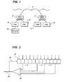
- FIG. 1 is a block diagram showing an example of a communication architecture, within which embodiments of the invention are practiced.
- FIG. 2 is a schematic diagram of circuitry for a data sequence generator.
- FIG. 3 is a flowchart showing a process, according to an embodiment of the invention, for verifying interoperability of an implementation with a standard.
- Verification of interoperability is done by defining a set of possible seed values, using the possible seed values to generate subcarrier bit streams and symbols having known pilot bit values, ruling out seed values based on their generated symbols if the pilot bits in the symbols don't match up with those pilot bits produced by the standard, and judging interoperability of the implementation with the standard, based on which, if any, of the possible seed values produce symbols compatible with the standard.
- Base stations 2 and 4 are coupled to a communication network 6, for communication thereover.
- Users 8, 10, 12, and 14 are coupled to the base stations 2 and 4, as shown.
- an analyzer 16 is coupled to the user 8 to receive, monitor and analyze a transmission signal generated by the implementation and transmitted from the user 8 to the base station 2.
- the implementation to be verified for interoperability is then tested, in a manner to be described.
- Interoperability between an implementation on the user 8 and, for instance, an implementation on the user 12 is verified by first verifying the user 8's implementation against the standard, and also verifying the user 12's implementation against the standard, using the analyzer 16, or another analyzer, similarly coupled to the user 12. If both users' implementations are interoperable with the standard, then they will be interoperable with each other.
- An OFDMA symbol is characterized in terms of a period of time during which signals on the subcarriers are modulated, for instance by a data sequence generator.
- a shift register 18 is loaded with an initial value, such as a PRBS seed value.
- the shift register 18 is then clocked repeatedly. For instance, in the circuitry of FIG. 2, bits within stages of the shift register 18 are shifted from left to right.
- the bit values within predetermined stages of the shift register 18 are tapped, and logically combined by means of combinational logic, here shown as a logic gate 20.
- the output of the combinational logic is coupled to an input 22 of the shift register 18.
- a data sequence in this case a bit stream, is produced at an output 24. That bit stream is used to modulate the signals on the various OFDM subcarriers.
- bit sequence generated after a given elapsed period of time will be a given, repeatable value. Also, different implementations compatible with the standard will, after the given elapsed time, generate the same given, repeatable value.
- the signals on the subcarriers to be modulated comprise data, idle signals, and/or pilot signals (discussed below). Accordingly, a communication signal, modulated in accordance with the bit sequence value, will be repeatable as well, except to the extent that the data portion of the signal to be modulated varies.
- Pilot symbols and data symbols are mapped onto subcarriers to form an OFDM symbol.
- the standard specifies when and where pilot symbols will occur, and what their values are.
- the implementation is verified to be compatible with a standard, as to the given OFDM symbol, if the pilot symbol bit values match that provided, in the standard, for the OFDM symbol.
- overall interoperability of the implementation with a standard can be verified by verifying the pilot symbols of the OFDM symbols.
- Orthogonal Frequency Division Multiplexing is characterized in terms of a set of subcarriers over a given frequency band. See, for instance IEEE 802.11a-1999, available from www.ieee802.org, and the IEEE standards library. Section 17.3 describes the 802.11a OFDM PHY layer including how to generate an OFDM signal with pilot and data symbols. It will be understood, however, that the invention is not limited to OFDM, or to 802.11 a. Alternatively, the invention also applies to more complicated structures, and to varying, rather than constant, PRBS such as 802.16e OFDMA. However, for illustrative purposes the 802.11a standard is here described, so as to show the transmission of OFDM.
- OFDM Orthogonal Frequency Division Multiplexing
- An OFDM symbol comprises one data symbol (made of M bits, where M is a predetermined integer value) for each subcarrier.
- an OFDM symbol can be expressed in terms of a binary word, in which there is are M bits for each subcarrier, and each bit has a respective value, based on the data value in the subcarrier.
- BPSK Binary Phase Shift Keying
- a given subcarrier will be carrying pilot information, such as a pilot symbol, which is a signal used for synchronization or reference purposes.
- pilot information such as a pilot symbol
- a given OFDM symbol will be made up of a mixture of data bits of unknown value, and known pilot symbol bits from the standard. Pilot symbols and data symbols are mapped onto subcarriers to form an OFDM symbol.
- the OFDM symbols thus contain pilot symbols, instead of data symbols, on some subcarriers.
- Pilot symbols on given subcarriers at given times, are characteristic of a given OFDM implementation.
- a BPSK modulation type is applied to the pilot symbols.
- the pilot or data symbols may be characterized in terms of a phase on the complex l+jQ plane.
- BPSK as an example, could be viewed as a pilot symbol of value 0 having phase 0 degrees, and a pilot symbol of value 1 having phase 180 degrees. That is, a 0 would indicate the signal on a given subcarrier remains at its current phase, whereas a 1 would indicate the signal on a given subcarrier would be rotated 180 degrees.
- BPSK is a modulation technique where the carrier is shifted by 180 degrees in accordance with a digital bit stream and with the specific data mapping employed. As an example, "0" would not produce a phase transition where as "1" would cause a phase transition to occur.
- the PRBS seed value is detected based upon the phase of the BPSK Pilots in the OFDM signal.
- pilot phases By converting the pilot phases into bits, a mixture of unknown data bits and known pilot phase bits is produced.
- the bit sequence will be sparse (that is, mostly unknown data bits and few known pilot bits), with one known bit for each pilot subcarrier.
- the method of the invention employs the pilot bits, and/or their phase values.
- a process is used to test the possible seed values.
- An example of the process, as per one embodiment of the invention, is set forth in FIG. 3.
- FIG. 3 is expressed partially in terms of "pseudo-code," the essential functionality of the method will be understood to persons skilled in the art. Variations in implementations, sequences of steps, etc., are understood to be within additional embodiments of the invention. Note, also, that while an OFDM symbol is described, other types of communications, for instance those referred to elsewhere in the present patent application, and others that would be known to those skilled in the art, may be used.
- the process of FIG. 3 involves deleting seeds from the set of possible seeds, if the seeds cannot generate a symbol having the pilot symbols on subcarriers, as per the standard. That is, given a detected symbol, for each subcarrier, detecting whether the subcarrier includes a pilot symbol and if so whether that pilot symbol would result from an interoperable implementation. For each subcarrier, the seeds in the set are tested. Seeds are eliminated from the set, if they result in a symbol having a pilot symbol, on any of the subcarriers, that does not match the pilot symbol expected from the standard.
- the received symbol is described as an OFDM symbol.
- a set of possible seed values suitable for the particular embodiment. For instance, a set of all N-bit seed values, where N is the length of the PRBS register, as defined in the standard, can be generated by taking the binary values 0 through 2 N -1, which are all of the 2 N possible binary bit values for a word of such length. Depending on the particular implementation, there may be reasons for omitting some of these 2 N possible binary bit values from the initial set of possible seed values.
- the process includes performing iterations (to be described) for each of the subcarriers.
- all subcarriers within the set are tested (block 26 of FIG. 3).
- the subcarrier symbol is a pilot symbol. If it is not a pilot symbol, then we move to the next subcarrier (blocks 28 and 30).
- the value of the pilot symbol is determined (block 32). In one embodiment, this determination can include a consideration of the phase of the symbol, as described above.
- a test (generally shown as block 34) is performed on each seed within the set of possible seeds.
- the test includes starting from the seed, generating a communication stream (block 36), and determining whether (block 38) the resultant communication stream can include the identified pilot symbol for this subcarrier.
- block 36 generating a communication stream
- block 38 determining whether the resultant communication stream can include the identified pilot symbol for this subcarrier.
- Each such seed is removed (block 40) from the set of possible seeds, since there will be no need to test the seed further, against other pilot symbols on other subcarriers.
- the set of possible seeds will dwindle in size, often rapidly.
- steps 28-36 may be repeated, with 0 and 1 swapped in the sequence generated in step 28. This would accommodate cases where BPSK pilots could be inverted in phase.
- step 46 If more than one seed remains (step 46), then this result indicates inconclusive PRBS seed detection, likely due to too few pilots to identify a unique seed. That is, not enough pilots were present in the symbol to conclusively determine whether the PRBS seed is an interoperable implementation. This result is reported to the user.
- step 48 If exactly one PRBS seed remains (step 48), then the result is that the one PRBS seed is deemed to correspond to the transmitted PRBS seed value. This result is reported to the user.
- the remaining seed is compared against the PRBS seed value that would result from parameters the user has specified in the measurement configuration. This comparison is reported to the user.
- the detected PRBS seed is compared to the PRBS seed value computed from user parameters. In one embodiment, both are compared. If the seed value is correct, and the register implementation is correct, then the generated bits will be correct.
- a "no match" indicator will tell the user that the PRBS sequence generation logic is incorrect, for instance, when the connections are to the wrong bits in the register.
- the PRBS sequence detection algorithm provided above may be performed twice with inverted bit sequences, to determine if a bit phase inversion has occurred. That is, the bit values might be '1' when phase from (-90, +90], and '0' otherwise.
- This embodiment may be illustrated with a flowchart similar to FIG. 3, but with the phase test (block 50) suitably inverted from what is shown in the flow chart of FIG. 3.
- an embodiment of the invention could be implemented using the operator "Real(B[s])>0" in place of the phase description of BPSK demodulation set forth above.
- Systems that include preferred embodiments of the invention may also provide other signal quality metrics to the user: For further information on such additional functionality, please consult product literature for such systems and equipment.
- product literature for the 89601A Vector Signal Analyzer, made and sold by Agilent Technologies, Inc., and described at http://www.agilent.com/find/89600, is incorporated by reference herein.
- a method for verifying interoperability can be implemented in an apparatus such as a piece of test equipment or other equipment, for instance the analyzer 16 of FIG. 1.
- the analyzer 16 is coupled to a user, as shown, to monitor a symbol from a communication stream, identify a symbol from the communication stream, the symbol comprising subcarrier symbols that may include pilot symbols, and perform the above-described interoperability test on that symbol.
- the method of the invention can be implemented in software, such as a software simulation, or using the other approaches set forth above (particularly those in the second paragraph of the Detailed Description).
- software embodiments of the invention may be provided as a computer program product, such as a CD-ROM or other computer-readable medium containing software, that a user can install onto computing or processing equipment such as programmable test equipment, that will enable the equipment to perform a method in accordance with embodiments of the invention described herein or otherwise understood from the description given herein.
- Such software may also be downloadable from a communication network such as the Internet.
Landscapes
- Engineering & Computer Science (AREA)
- Computer Networks & Wireless Communication (AREA)
- Signal Processing (AREA)
- Mobile Radio Communication Systems (AREA)
- Monitoring And Testing Of Transmission In General (AREA)
Abstract
Description
- The invention relates to communications, and has applicability to Metropolitan Area Networks according to the IEEE 802.16 WirelessMAN standard.
- In a typical communication system architecture, users are coupled for communication to one or more nodes, such as base stations, which, in turn, are coupled for communication to public communication networks such as the Internet. Communication streams between such users pass through their respective base stations, and across the public networks.
- Such communication streams are multiplexed within distinct frequency bands through techniques such as Orthogonal Frequency Division Multiplexing (OFDM) and Orthogonal Frequency Division Multiple Access (OFDMA). For instance, implementations of OFDMA include a physical (PHY) layer, and employ subcarriers having complex symbols (that is, symbols that include both real and imaginary components, and therefore can be characterized as having a phase). The complex symbols are modulated using a PseudoRandom Bit Sequence (PRBS), which is generated from a seed value using PRBS generator register circuitry.
- A user will employ an implementation of PRBS generator register circuitry, and of seed values. The user may develop the implementation him/herself, or may obtain it from a vendor. For instance, as the 802.16 standard becomes more accepted and commonplace, different implementations will become available from different vendors. Most such implementations will be in the form of 802.16e-OFDMA PHY chip designs. Such designs typically are highly integrated; that is, the PRBS function is integrated with the rest of the modulator, so it is probably done independently by each chip manufacturer.
- In order for communication to take place between different users, their respective implementations of the seed value and the PRBS generator register circuitry should be interoperable. Failure to communicate can be due to lack of such interoperability. Therefore, it is desirable that, for a given implementation of an OFDMA transmitter, interoperability with other implementations can be verified.
- Conventionally, interoperability verification of PRBS generator implementations (in particular, implementations of the PRBS generator register circuitry and the seed values) has been done ad-hoc and manually. The ad-hoc check has been done when interoperability problems or questions arise. A comparison is done between two implementations (usually the symbol bit output generated from a given PRBS seed) and then differences between them are identified (either in the filling of the PRBS register, or in the sequence output). This manual approach required working across implementations for comparison without independent verification. It also has required cooperation between different service provider companies, or between different hardware vendors.
- Such conventional verification has been disadvantageous, among other reasons because the necessary cooperation between different companies may not always be available, and because the lack of independent verification makes it difficult to ensure interoperability proactively. Rather, interoperability problems can only be solved reactively, in response to observed communication problems.
- Verifying interoperability of an implementation of a communication standard is done by monitoring a symbol comprising a set of subcarrier symbols (e.g., an OFDM symbol) in a communication stream produced by the implementation. Some of the subcarrier symbols of the symbol are generated from pilot symbols, transmitted on subcarriers in accordance with the standard. For a given implementation and a given symbol, it is known which subcarriers will be pilot symbols, and what their pilot symbol values will be. Verification involves verifying that the pilot symbols will be produced from an interoperable implementation of circuitry and seed value. Verifying interoperability between two implementations may then be done proactively, by verifying each one against the standard.
- Further features and advantages of the present invention, as well as the structure and operation of preferred embodiments of the present invention, are described in detail below with reference to the accompanying exemplary drawings.
- FIG. 1 is a block diagram showing an example of a communication architecture, within which embodiments of the invention are practiced.
- FIG. 2 is a schematic diagram of circuitry for a data sequence generator.
- FIG. 3 is a flowchart showing a process, according to an embodiment of the invention, for verifying interoperability of an implementation with a standard.
- In the description of the invention which follows, references will be made to OFDM and OFDMA, in connection with exemplary embodiments. It will be understood that the invention has applicability in both the OFDM and OFDMA environments. Therefore, references to either OFDM or OFDMA are not intended to limit the applicability of the invention to these and other environments.
- Verification of interoperability is done by defining a set of possible seed values, using the possible seed values to generate subcarrier bit streams and symbols having known pilot bit values, ruling out seed values based on their generated symbols if the pilot bits in the symbols don't match up with those pilot bits produced by the standard, and judging interoperability of the implementation with the standard, based on which, if any, of the possible seed values produce symbols compatible with the standard.
- The environment, in which the invention is practiced, is illustrated by the block diagram of FIG. 1. Base stations 2 and 4 are coupled to a
communication network 6, for communication thereover.Users user 8, is to be verified for interoperability in a manner to be described below, ananalyzer 16 is coupled to theuser 8 to receive, monitor and analyze a transmission signal generated by the implementation and transmitted from theuser 8 to the base station 2. - It will be understood that there are other environments that are foreseeable alternatives to this initial description, such as 1) Use of a base station emulator or simulator instead of an actual network; 2) Use of test signals from the user terminals, to eliminate any connection to the network or emulator; and 3) User terminal simulation connected to test equipment (no actual hardware involved, interoperability testing performed entirely within the simulation). The invention set forth herein also applies to such other environments.
- In this configuration, the implementation to be verified for interoperability is then tested, in a manner to be described. Interoperability between an implementation on the
user 8 and, for instance, an implementation on theuser 12 is verified by first verifying theuser 8's implementation against the standard, and also verifying theuser 12's implementation against the standard, using theanalyzer 16, or another analyzer, similarly coupled to theuser 12. If both users' implementations are interoperable with the standard, then they will be interoperable with each other. - It would be possible, in theory, to verify interoperability by verifying, by means of directly comparing the hardware and software implementations, to verify that they are the same. In practice, however, this is not possible because the party wishing to do the verification does not have direct access to either the bit sequence generator circuitry, or to the seed values loaded into the
shift register 18. Rather, theanalyzer 16 only has access to the bit stream coming from theoutput 22 of the implementation being tested. Therefore, verification of interoperability is performed by, in essence, comparing a bit stream generated in accordance with the standard, to the bit stream received from theoutput 22. - A more detailed description of the interoperability verification process will now be described. An OFDMA symbol is characterized in terms of a period of time during which signals on the subcarriers are modulated, for instance by a data sequence generator. Consider, for instance, the data sequence generator of FIG. 2. A
shift register 18 is loaded with an initial value, such as a PRBS seed value. Theshift register 18 is then clocked repeatedly. For instance, in the circuitry of FIG. 2, bits within stages of theshift register 18 are shifted from left to right. The bit values within predetermined stages of theshift register 18 are tapped, and logically combined by means of combinational logic, here shown as alogic gate 20. The output of the combinational logic is coupled to aninput 22 of theshift register 18. Thus, once the seed value is loaded into theshift register 18, and clocking begins, a data sequence, in this case a bit stream, is produced at anoutput 24. That bit stream is used to modulate the signals on the various OFDM subcarriers. - When a given period of time, characteristic of a given OFDMA symbol, has elapsed, there will be a certain bit value in the
shift register 18. For a given implementation of the seed value and the PRBS generator register circuitry, the bit sequence generated after a given elapsed period of time will be a given, repeatable value. Also, different implementations compatible with the standard will, after the given elapsed time, generate the same given, repeatable value. - The signals on the subcarriers to be modulated comprise data, idle signals, and/or pilot signals (discussed below). Accordingly, a communication signal, modulated in accordance with the bit sequence value, will be repeatable as well, except to the extent that the data portion of the signal to be modulated varies.
- Pilot symbols and data symbols are mapped onto subcarriers to form an OFDM symbol. The standard specifies when and where pilot symbols will occur, and what their values are. The implementation is verified to be compatible with a standard, as to the given OFDM symbol, if the pilot symbol bit values match that provided, in the standard, for the OFDM symbol. Thus, overall interoperability of the implementation with a standard can be verified by verifying the pilot symbols of the OFDM symbols.
- For example, Orthogonal Frequency Division Multiplexing (OFDM) is characterized in terms of a set of subcarriers over a given frequency band. See, for instance IEEE 802.11a-1999, available from www.ieee802.org, and the IEEE standards library. Section 17.3 describes the 802.11a OFDM PHY layer including how to generate an OFDM signal with pilot and data symbols. It will be understood, however, that the invention is not limited to OFDM, or to 802.11 a. Alternatively, the invention also applies to more complicated structures, and to varying, rather than constant, PRBS such as 802.16e OFDMA. However, for illustrative purposes the 802.11a standard is here described, so as to show the transmission of OFDM.
- An OFDM symbol comprises one data symbol (made of M bits, where M is a predetermined integer value) for each subcarrier. Thus, an OFDM symbol can be expressed in terms of a binary word, in which there is are M bits for each subcarrier, and each bit has a respective value, based on the data value in the subcarrier. For instance, OFDM using BPSK modulation and having 841 subcarriers will have data symbols of M=1 bits per symbol, so a Binary Phase Shift Keying (BPSK) OFDM symbol will contain 841 bits. QPSK modulation has data symbols of M=2 bits per symbol, so, in this case a QPSK OFDM symbol will contain 1682 bits.
- It will sometimes be the case that a given subcarrier will be carrying pilot information, such as a pilot symbol, which is a signal used for synchronization or reference purposes. Which subcarriers are carrying pilot symbols at a given point in time, and the value (in the case of BPSK pilot symbols, 0 or 1) of a given pilot symbol at a given time, are known from the standard.
- Therefore, a given OFDM symbol will be made up of a mixture of data bits of unknown value, and known pilot symbol bits from the standard. Pilot symbols and data symbols are mapped onto subcarriers to form an OFDM symbol. The OFDM symbols thus contain pilot symbols, instead of data symbols, on some subcarriers.
- Pilot symbols, on given subcarriers at given times, are characteristic of a given OFDM implementation. In many OFDM implementations, a BPSK modulation type is applied to the pilot symbols. The pilot or data symbols may be characterized in terms of a phase on the complex l+jQ plane. BPSK, as an example, could be viewed as a pilot symbol of
value 0 havingphase 0 degrees, and a pilot symbol ofvalue 1 having phase 180 degrees. That is, a 0 would indicate the signal on a given subcarrier remains at its current phase, whereas a 1 would indicate the signal on a given subcarrier would be rotated 180 degrees. This is how the BPSK pilot symbols are "demodulated" or "demapped" into pilot bits. BPSK is a modulation technique where the carrier is shifted by 180 degrees in accordance with a digital bit stream and with the specific data mapping employed. As an example, "0" would not produce a phase transition where as "1" would cause a phase transition to occur. - In one embodiment of the method of the invention, the PRBS seed value is detected based upon the phase of the BPSK Pilots in the OFDM signal. By converting the pilot phases into bits, a mixture of unknown data bits and known pilot phase bits is produced. The bit sequence will be sparse (that is, mostly unknown data bits and few known pilot bits), with one known bit for each pilot subcarrier. The method of the invention employs the pilot bits, and/or their phase values.
- Therefore, in an embodiment of the invention, it is possible to use a PRBS sequence elimination procedure, to determine which possible seed values, used for modulating subcarriers carrying known pilot symbols at known times, could result in the observed OFDM symbol. Interoperability of the implementation can then be verified, by verifying that the seed value thusly determined matches that of the standard.
- In accordance with one embodiment of the invention, a process is used to test the possible seed values. An example of the process, as per one embodiment of the invention, is set forth in FIG. 3.
- While FIG. 3 is expressed partially in terms of "pseudo-code," the essential functionality of the method will be understood to persons skilled in the art. Variations in implementations, sequences of steps, etc., are understood to be within additional embodiments of the invention. Note, also, that while an OFDM symbol is described, other types of communications, for instance those referred to elsewhere in the present patent application, and others that would be known to those skilled in the art, may be used.
- The process of FIG. 3 involves deleting seeds from the set of possible seeds, if the seeds cannot generate a symbol having the pilot symbols on subcarriers, as per the standard. That is, given a detected symbol, for each subcarrier, detecting whether the subcarrier includes a pilot symbol and if so whether that pilot symbol would result from an interoperable implementation. For each subcarrier, the seeds in the set are tested. Seeds are eliminated from the set, if they result in a symbol having a pilot symbol, on any of the subcarriers, that does not match the pilot symbol expected from the standard.
- Initially, there is a received, or measured, symbol made up of subcarrier symbols for each of the subcarriers. In FIG. 3, the received symbol is described as an OFDM symbol.
- Initially, there is also a set of possible seed values suitable for the particular embodiment. For instance, a set of all N-bit seed values, where N is the length of the PRBS register, as defined in the standard, can be generated by taking the
binary values 0 through 2N -1, which are all of the 2N possible binary bit values for a word of such length. Depending on the particular implementation, there may be reasons for omitting some of these 2N possible binary bit values from the initial set of possible seed values. - The process includes performing iterations (to be described) for each of the subcarriers. In one embodiment, all subcarriers within the set are tested (block 26 of FIG. 3).
- For the subcarrier being tested, it is ascertained whether the subcarrier symbol is a pilot symbol. If it is not a pilot symbol, then we move to the next subcarrier (blocks 28 and 30).
- If the subcarrier symbol is a pilot symbol, then the value of the pilot symbol is determined (block 32). In one embodiment, this determination can include a consideration of the phase of the symbol, as described above.
- For the pilot symbol, a test (generally shown as block 34) is performed on each seed within the set of possible seeds. The test includes starting from the seed, generating a communication stream (block 36), and determining whether (block 38) the resultant communication stream can include the identified pilot symbol for this subcarrier. As this part of the process tests the various possible seeds, it often will be found that many of the possible seeds cannot produce the identified pilot symbol. Each such seed is removed (block 40) from the set of possible seeds, since there will be no need to test the seed further, against other pilot symbols on other subcarriers. Thus, as seeds are successively tested to see if they can generate the identified pilot symbol, the set of possible seeds will dwindle in size, often rapidly.
- When the seeds have been tested against one pilot symbol on one subcarrier, we look to the next subcarrier, and the next, etc., (block 42), to find additional pilot symbols and test the remaining seeds in the dwindling set in the manner just described.
- After all subcarriers have been tested (block 26), conclusions are drawn based on the number of possible seeds remaining. The result of the above process is that a set of seed values that produce correct pilot bits is identified. Seed values within the set are capable of generating the identified pilot symbols in the OFDM symbol. There can be either zero such seed values, exactly one, or more than one.
- If no seeds remain (step 44), then it indicates the PRBS generator used by the signal does not conform to 802.16 OFDMA, report this to user. In one embodiment of the invention, steps 28-36 may be repeated, with 0 and 1 swapped in the sequence generated in
step 28. This would accommodate cases where BPSK pilots could be inverted in phase. - If more than one seed remains (step 46), then this result indicates inconclusive PRBS seed detection, likely due to too few pilots to identify a unique seed. That is, not enough pilots were present in the symbol to conclusively determine whether the PRBS seed is an interoperable implementation. This result is reported to the user.
- If exactly one PRBS seed remains (step 48), then the result is that the one PRBS seed is deemed to correspond to the transmitted PRBS seed value. This result is reported to the user.
- Additionally, the remaining seed is compared against the PRBS seed value that would result from parameters the user has specified in the measurement configuration. This comparison is reported to the user.
- The detected PRBS seed is compared to the PRBS seed value computed from user parameters. In one embodiment, both are compared. If the seed value is correct, and the register implementation is correct, then the generated bits will be correct.
- Presenting the PRBS seed value which was detected (if the PRBS bit sequence was conforming to the standard), will tell the user if they have loaded the register correctly based upon the parameters which define the PRBS seed at that instant. For instance, one possible problem that would be detected would be that the register, or a portion of it, was incorrectly loaded least significant bit (LSB) to most significant bit (MSB), or vice-versa, not matching the standard. This problem is sometimes called wrong "endian-ness." Thus, problems may be detected, such as incorrectly interpreting the endian ordering of bits loaded into the PRBS register.
- Also, a "no match" indicator will tell the user that the PRBS sequence generation logic is incorrect, for instance, when the connections are to the wrong bits in the register.
- This means the user does not need to understand the PRBS definition to determine if the PRBS sequence is correct, they just set up the base user parameters, and the PRBS seed comparison is performed automatically.
- The PRBS sequence detection algorithm provided above may be performed twice with inverted bit sequences, to determine if a bit phase inversion has occurred. That is, the bit values might be '1' when phase from (-90, +90], and '0' otherwise. This embodiment may be illustrated with a flowchart similar to FIG. 3, but with the phase test (block 50) suitably inverted from what is shown in the flow chart of FIG. 3. Also, an embodiment of the invention could be implemented using the operator "Real(B[s])>0" in place of the phase description of BPSK demodulation set forth above.
- Systems that include preferred embodiments of the invention may also provide other signal quality metrics to the user: For further information on such additional functionality, please consult product literature for such systems and equipment. In particular, publicly available product literature for the 89601A Vector Signal Analyzer, made and sold by Agilent Technologies, Inc., and described at http://www.agilent.com/find/89600, is incorporated by reference herein.
- Thus, it is possible proactively to determine whether two implementations are interoperable, by performing the above test for each of the implementations. They will be interoperable with each other, if each one is found to be interoperable with the standard. Such interoperability tests on multiple implementations can be done simultaneously, or one at a time, using the
same analyzer 16, coupled to one user at a time. - A method for verifying interoperability, as described above, can be implemented in an apparatus such as a piece of test equipment or other equipment, for instance the
analyzer 16 of FIG. 1. Theanalyzer 16 is coupled to a user, as shown, to monitor a symbol from a communication stream, identify a symbol from the communication stream, the symbol comprising subcarrier symbols that may include pilot symbols, and perform the above-described interoperability test on that symbol. - Also, the method of the invention can be implemented in software, such as a software simulation, or using the other approaches set forth above (particularly those in the second paragraph of the Detailed Description). In particular, software embodiments of the invention may be provided as a computer program product, such as a CD-ROM or other computer-readable medium containing software, that a user can install onto computing or processing equipment such as programmable test equipment, that will enable the equipment to perform a method in accordance with embodiments of the invention described herein or otherwise understood from the description given herein. Such software may also be downloadable from a communication network such as the Internet.
- Although the present invention has been described in detail with reference to particular embodiments, persons possessing ordinary skill in the art to which this invention pertains will appreciate that various modifications and enhancements may be made without departing from the spirit and scope of the claims that follow.
Claims (10)
- An apparatus (16) for verifying interoperability of an implementation of a communication standard with the communication standard, the apparatus comprising:means for generating a communication stream (26) containing pilot information;means for comparing the pilot information with pilot information expected from an implementation that is interoperable with the standard (26); andmeans for determining interoperability (44, 46, 48) based on the result of the comparing.
- An apparatus as recited in claim 1, wherein the means for generating (26) includes:means for creating a set of seed values (18); andmeans for generating the communication stream using the seed values (18).
- An apparatus as recited in claim 2, wherein the means for creating a set of seed values (18) includes means for creating a set of words, each word being of a predetermined bit length and comprising a respective bit combination.
- An apparatus as recited in claim 3, wherein:each word has a bit length N, where N is an integer;the set of words includes 2N words, andthe words include all possible bit combinations.
- An apparatus as recited in claim 2, wherein the means for generating the communication stream (26) further includes:means for loading one of the seed values into a data sequence generator (18); andmeans for operating the data sequence generator to generate a communicationstream (24) from the loaded seed value.
- An apparatus as recited in claim 5, wherein:a communication stream (24) generated from an interoperable implementation will contain expected pilot symbols;the means for generating the communication stream further includes means for generating a communication stream containing pilot symbols; andthe means for comparing includes:means for identifying the pilot symbols from the generated communication stream (28); andmeans for comparing the identified pilot symbols with the expected pilot symbols (38).
- An apparatus as recited in claim 6, wherein the means for comparing (38) further includes means for examining a phase of the pilot symbols from the generated communication stream.
- An apparatus as recited in claim 5, further comprising:means for using each seed value (26) into the data sequence generator (18); andmeans for operating the data sequence generator to generate a respectivecommunication stream (24) from each seed value, each communication stream including a generated symbol.
- An apparatus as recited in claim 8, wherein the means for determining includes, for a given one of the seed values:means for identifying a pilot symbol in the generated symbol (28, 32)I;means for comparing (34) the identified pilot symbols with the expected pilot symbols;based on the comparing, means for determining whether there is a match between the expected pilot symbol and the identified pilot symbol (38); andmeans for removing (40) the given seed value from the set of seed values if there is not a match between the identified pilot symbol and the expected pilot symbol.
- An apparatus as recited in claim 9, wherein the means for determining (44, 46, 48) further includes:means for determining a number of seed values remaining in the set of seed values after comparing (40);means, operable if the number of remaining seed values is zero (44), for determining that the implementation is not interoperable;means, operable if the number of remaining seed values is one (48), for determining that the implementation is interoperable; andmeans, operable if the number of remaining seed values is greater than one (46), for determining that it is uncertain whether the implementation is interoperable.
Applications Claiming Priority (1)
| Application Number | Priority Date | Filing Date | Title |
|---|---|---|---|
| US11/347,631 US7652975B2 (en) | 2006-02-03 | 2006-02-03 | Interoperability verification for implementation according to communication standard |
Publications (2)
| Publication Number | Publication Date |
|---|---|
| EP1816779A2 true EP1816779A2 (en) | 2007-08-08 |
| EP1816779A3 EP1816779A3 (en) | 2009-09-16 |
Family
ID=38117215
Family Applications (1)
| Application Number | Title | Priority Date | Filing Date |
|---|---|---|---|
| EP07001627A Withdrawn EP1816779A3 (en) | 2006-02-03 | 2007-01-25 | Interoperability verification for implementation according to communication standard |
Country Status (2)
| Country | Link |
|---|---|
| US (1) | US7652975B2 (en) |
| EP (1) | EP1816779A3 (en) |
Families Citing this family (1)
| Publication number | Priority date | Publication date | Assignee | Title |
|---|---|---|---|---|
| US7907637B2 (en) * | 2008-04-04 | 2011-03-15 | Newport Media, Inc. | Fast acquisition in mobile multimedia multicast systems |
Family Cites Families (13)
| Publication number | Priority date | Publication date | Assignee | Title |
|---|---|---|---|---|
| US5228042A (en) * | 1991-02-07 | 1993-07-13 | Northern Telecom Limited | Method and circuit for testing transmission paths |
| US5258936A (en) * | 1992-08-05 | 1993-11-02 | Motorola, Inc. | Method and apparatus for generating pseudo-random numbers |
| US6201829B1 (en) * | 1998-04-03 | 2001-03-13 | Adaptec, Inc. | Serial/parallel GHZ transceiver with pseudo-random built in self test pattern generator |
| KR20010035967A (en) * | 1999-10-05 | 2001-05-07 | 서평원 | Apparatus for acquiring synchronization of multi user in CDMA receiver |
| KR100354168B1 (en) * | 2000-10-31 | 2002-09-27 | 엘지전자 주식회사 | Method and system for handoff communication mobile CDMA |
| US7385929B1 (en) * | 2001-09-25 | 2008-06-10 | Atheros Communications, Inc. | Method and system for detecting false packets in wireless communications systems |
| US7599305B2 (en) * | 2003-03-05 | 2009-10-06 | The Boeing Company | Systems and methods for providing collaboration between systems |
| US7453793B1 (en) * | 2003-04-10 | 2008-11-18 | Qualcomm Incorporated | Channel estimation for OFDM communication systems including IEEE 802.11A and extended rate systems |
| DE60313860D1 (en) * | 2003-06-24 | 2007-06-28 | St Microelectronics Srl | Integrated circuit with improved BIST circuit for performing a structured test |
| US7336600B2 (en) * | 2003-12-29 | 2008-02-26 | Industrial Technology Research Institute | Cell search method for orthogonal frequency division multiplexing based cellular communication system |
| US7031280B2 (en) * | 2004-04-26 | 2006-04-18 | Motorola, Inc. | Method and apparatus for hand over of calls |
| US7852822B2 (en) * | 2004-12-22 | 2010-12-14 | Qualcomm Incorporated | Wide area and local network ID transmission for communication systems |
| US7562284B2 (en) * | 2005-08-26 | 2009-07-14 | International Business Machines Corporation | Apparatus, system, and method for mandatory end to end integrity checking in a storage system |
-
2006
- 2006-02-03 US US11/347,631 patent/US7652975B2/en not_active Expired - Fee Related
-
2007
- 2007-01-25 EP EP07001627A patent/EP1816779A3/en not_active Withdrawn
Also Published As
| Publication number | Publication date |
|---|---|
| EP1816779A3 (en) | 2009-09-16 |
| US20070183302A1 (en) | 2007-08-09 |
| US7652975B2 (en) | 2010-01-26 |
Similar Documents
| Publication | Publication Date | Title |
|---|---|---|
| US7305025B2 (en) | Measurement instrument and measurement method | |
| EP4070483B1 (en) | Determining error vector magnitude using cross-correlation | |
| WO2003093846A1 (en) | Measurement device and measurement method | |
| US8953657B2 (en) | Packet detector | |
| KR20040015141A (en) | System and Method For Loop Characterization From Double-Ended Measurements | |
| CN105847210B (en) | Vector Signal Generator Channel Characterization Using Quadrature Modulation | |
| US11528121B2 (en) | Receiving device and receiving method, and mobile terminal test apparatus provided with receiving device | |
| US7652975B2 (en) | Interoperability verification for implementation according to communication standard | |
| US7933321B2 (en) | Measuring system with a reference signal between a signal generator and a signal analyzer | |
| US11539605B2 (en) | Channel quality determination | |
| US10171127B2 (en) | Method, system and computer program for synchronizing pseudorandom binary sequence modules | |
| JP5170939B2 (en) | Test apparatus and test method | |
| US7697617B2 (en) | Synchronisation method and apparatus for OFDM symbols | |
| Fan et al. | A versatile high speed bit error rate testing scheme | |
| KR100872861B1 (en) | Bit error rate test method in the PRS pattern | |
| Halder et al. | System-level specification testing of wireless transceivers | |
| US20250380147A1 (en) | Simulating a network node, and testing a network node | |
| Tahraoui et al. | Digital generation of RF phase-modulated test stimuli: application to BPSK modulation scheme | |
| Lipovac et al. | Closed-form enhanced detection of clipped OFDM symbol | |
| Vayssade et al. | Low-cost EVM measurement of ZigBee transmitters from 1-bit undersampled acquisition | |
| Jakubík | SDR all-channels receiver for FHSS sensor network | |
| Yilmaz et al. | Built-in EVM measurement for OFDM transceivers using all-digital DFT | |
| US20170012807A1 (en) | Method and apparatus for extraction of baseband waveform from amplitude modulated signal via time domain sampling | |
| JP2022064098A (en) | Frame synchronization device, measurement device and measurement system equipped with frame synchronization device, and frame synchronization method and measurement method | |
| US6651195B1 (en) | Method and system for bit error structure measurements of data transmission channels |
Legal Events
| Date | Code | Title | Description |
|---|---|---|---|
| PUAI | Public reference made under article 153(3) epc to a published international application that has entered the european phase |
Free format text: ORIGINAL CODE: 0009012 |
|
| AK | Designated contracting states |
Kind code of ref document: A2 Designated state(s): AT BE BG CH CY CZ DE DK EE ES FI FR GB GR HU IE IS IT LI LT LU LV MC NL PL PT RO SE SI SK TR |
|
| AX | Request for extension of the european patent |
Extension state: AL BA HR MK YU |
|
| PUAL | Search report despatched |
Free format text: ORIGINAL CODE: 0009013 |
|
| AK | Designated contracting states |
Kind code of ref document: A3 Designated state(s): AT BE BG CH CY CZ DE DK EE ES FI FR GB GR HU IE IS IT LI LT LU LV MC NL PL PT RO SE SI SK TR |
|
| AX | Request for extension of the european patent |
Extension state: AL BA HR MK RS |
|
| RIC1 | Information provided on ipc code assigned before grant |
Ipc: H04W 24/06 20090101ALN20090813BHEP Ipc: H04L 1/24 20060101AFI20070615BHEP |
|
| RAP1 | Party data changed (applicant data changed or rights of an application transferred) |
Owner name: AGILENT TECHNOLOGIES, INC. |
|
| STAA | Information on the status of an ep patent application or granted ep patent |
Free format text: STATUS: THE APPLICATION IS DEEMED TO BE WITHDRAWN |
|
| 18D | Application deemed to be withdrawn |
Effective date: 20090801 |