EP1816524A2 - Image forming device with optional paper cassette - Google Patents
Image forming device with optional paper cassette Download PDFInfo
- Publication number
- EP1816524A2 EP1816524A2 EP06022424A EP06022424A EP1816524A2 EP 1816524 A2 EP1816524 A2 EP 1816524A2 EP 06022424 A EP06022424 A EP 06022424A EP 06022424 A EP06022424 A EP 06022424A EP 1816524 A2 EP1816524 A2 EP 1816524A2
- Authority
- EP
- European Patent Office
- Prior art keywords
- recording paper
- optional
- paper cassette
- paper
- cassette
- Prior art date
- Legal status (The legal status is an assumption and is not a legal conclusion. Google has not performed a legal analysis and makes no representation as to the accuracy of the status listed.)
- Withdrawn
Links
- 230000005540 biological transmission Effects 0.000 claims abstract description 52
- 230000032258 transport Effects 0.000 claims abstract description 13
- 238000011144 upstream manufacturing Methods 0.000 claims abstract description 9
- 230000007246 mechanism Effects 0.000 claims description 51
- 238000004519 manufacturing process Methods 0.000 description 3
- 230000004044 response Effects 0.000 description 3
- 230000008859 change Effects 0.000 description 1
- 238000000034 method Methods 0.000 description 1
- 238000012986 modification Methods 0.000 description 1
- 230000004048 modification Effects 0.000 description 1
- 230000002093 peripheral effect Effects 0.000 description 1
- 230000008569 process Effects 0.000 description 1
- 230000000717 retained effect Effects 0.000 description 1
Images


Classifications
-
- G—PHYSICS
- G03—PHOTOGRAPHY; CINEMATOGRAPHY; ANALOGOUS TECHNIQUES USING WAVES OTHER THAN OPTICAL WAVES; ELECTROGRAPHY; HOLOGRAPHY
- G03G—ELECTROGRAPHY; ELECTROPHOTOGRAPHY; MAGNETOGRAPHY
- G03G15/00—Apparatus for electrographic processes using a charge pattern
- G03G15/65—Apparatus which relate to the handling of copy material
- G03G15/6502—Supplying of sheet copy material; Cassettes therefor
-
- G—PHYSICS
- G03—PHOTOGRAPHY; CINEMATOGRAPHY; ANALOGOUS TECHNIQUES USING WAVES OTHER THAN OPTICAL WAVES; ELECTROGRAPHY; HOLOGRAPHY
- G03G—ELECTROGRAPHY; ELECTROPHOTOGRAPHY; MAGNETOGRAPHY
- G03G2215/00—Apparatus for electrophotographic processes
- G03G2215/00362—Apparatus for electrophotographic processes relating to the copy medium handling
- G03G2215/00367—The feeding path segment where particular handling of the copy medium occurs, segments being adjacent and non-overlapping. Each segment is identified by the most downstream point in the segment, so that for instance the segment labelled "Fixing device" is referring to the path between the "Transfer device" and the "Fixing device"
- G03G2215/00379—Copy medium holder
- G03G2215/00383—Cassette
-
- G—PHYSICS
- G03—PHOTOGRAPHY; CINEMATOGRAPHY; ANALOGOUS TECHNIQUES USING WAVES OTHER THAN OPTICAL WAVES; ELECTROGRAPHY; HOLOGRAPHY
- G03G—ELECTROGRAPHY; ELECTROPHOTOGRAPHY; MAGNETOGRAPHY
- G03G2215/00—Apparatus for electrophotographic processes
- G03G2215/00362—Apparatus for electrophotographic processes relating to the copy medium handling
- G03G2215/00367—The feeding path segment where particular handling of the copy medium occurs, segments being adjacent and non-overlapping. Each segment is identified by the most downstream point in the segment, so that for instance the segment labelled "Fixing device" is referring to the path between the "Transfer device" and the "Fixing device"
- G03G2215/00396—Pick-up device
Definitions
- the present invention relates to an image forming device used in a copy machine, a facsimile, and a printer.
- a conventional image forming device In a conventional image forming device, optional paper cassettes are sequentially added from top to bottom below a device main body. Thus, a large number of papers can be stacked. Also, various sized recording papers and various types of recording papers can be stacked and selectively used.
- Power to feed and transport the recording paper from the optional paper cassette is transmitted from a motor mounted in the device main body to the optional paper cassette.
- the conventional image forming device has only one power transmission path. Accordingly, if a failure occurs in the motor or a component of the power transmission path, a paper feeding mechanism and a paper transporting mechanism of the optional paper cassette may stop operating partially or entirely. Also, in the case in which the device main body is mounted with a plurality of optional paper cassettes, one motor causes a lack of torque in some specifications. As a result, the paper feeding mechanism and the paper transporting mechanism of all of the optional paper cassettes may stop operating. In order to overcome the above-described problems, extra motors are added just to drive the paper feeding mechanism and the paper transporting mechanism of the optional paper cassettes. In such a case, however, an optional paper cassette with another power transmission path is needed to be replaced, resulting in an increase of manufacturing cost.
- one motor in the device main body drives all of the paper feeding mechanism and the paper transporting mechanism. Therefore, each time as the optional paper cassette is added, a load on the motor increases. Accordingly, assuming that a plurality of optional paper cassettes are added to the device main body, the device main body is pre-designed to be mounted with an expensive motor having a large power output. Otherwise, according to some specifications of the motor in the device main body, a lack of torque may occur when the motor drives the paper transporting mechanism of the optional paper cassette. When the recording paper is fed from a main cassette or an upper optional paper cassette, the motor simultaneously drives the paper transporting mechanism of lower optional paper cassettes, which do not need to operate. As a result, the power is consumed wastefully.
- a feed roller which is mounted along the recording paper transportation path in the optional paper cassette, transports the recording paper towards the device main body.
- all of the motors mounted in the paper cassettes located above the fourth optional paper cassette are also required to be driven. As a result, the power is consumed wastefully.
- an image forming device can provide a plurality of operation patterns (a combination of a power source and a power transmission path) of both a paper feeding mechanism and a paper transporting mechanism of an optional paper cassette. Therefore, an appropriate operation pattern can be selected accordingly.
- the image forming device includes at least one optional paper cassette for paper feeding vertically mounted below a device main body having an image forming portion.
- a recording paper is transported from the optional paper cassette to the image forming portion through a recording paper transportation path in the optional paper cassette and a recording paper transportation path in the device main body.
- Each optional paper cassette has a recording paper storage portion, a pickup roller, and a feed roller.
- a pile of recording papers is stacked in the recording paper storage portion.
- the pickup roller picks up the recording paper from the recording paper storage portion towards the recording paper transportation path in the optional paper cassette.
- the feed roller transports the recording paper from upstream to downstream through the recording paper transportation path in the optional paper cassette.
- the combination of the power source and the power transmission path, which are used to drive the pickup roller and the feed roller can be optionally changed. As a result, a plurality of operation patterns can be constructed.
- a user or a service person can change the operation pattern.
- the user can avoid a state in which the optional paper cassettes become partially or entirely inoperative.
- an appropriate operation pattern can be selected accordingly.
- the image forming device of the present invention includes at least one optional paper cassette used for paper feeding vertically mounted below a device main body.
- a recording paper is transported from the optional paper cassette to an image forming portion through a recording paper transportation path in the optional paper cassette and a recording paper transportation path in the device main body.
- the power transmission path is constructed using only gears attached to a bracket, which is mounted in each optional paper cassette.
- the bracket is mounted with a plurality of gear attaching portions so that a path of gear range can be changed accordingly.
- the power transmission path in the optional paper cassette can be optionally changed.
- the power transmission path is constructed using only the gears, a power loss can be reduced.
- the power source is either a main motor mounted in the device main body or a sub motor mounted in each optional paper cassette.
- the operation pattern of the pickup roller and the feed roller can be changed.
- the user can avoid a state in which the optional paper cassettes become inoperative.
- an appropriate operation pattern can be selected accordingly.
- a load on a motor in a device main body can be reduced when an optional paper cassette is used. In addition, power is not consumed wastefully.
- an image forming device includes at least one optional paper cassette used for paper feeding vertically mounted below the device main body having an image forming portion.
- a recording paper is transported from the optional paper cassette to the image forming portion through recording paper transportation paths in both the optional paper cassette and the device main body.
- Each optional paper cassette has a recording paper storage portion, a pickup roller, a feed roller, and a motor.
- a pile of recording papers is stacked in the recording paper storage portion.
- the pickup roller picks up the recording paper from the recording paper storage portion towards the recording paper transportation path in the optional paper cassette.
- the feed roller transports the recording paper from upstream to downstream through the recording paper transportation path in the optional paper cassette.
- the pickup roller is rotated by power transmitted from the motor mounted in the same optional paper cassette as the pickup roller.
- the feed roller is rotated by power transmitted from the motor mounted in an optional paper cassette located below the optional paper cassette where such rotated feed roller is provided.
- the image forming device is not required to include an expensive motor having a large power output in the device main body. Therefore, a manufacturing cost of the image forming device can be reduced.
- the optional paper cassettes can be added without considering the load on the motor in the device main body.
- each optional paper cassette has an output transmission mechanism and an input transmission mechanism.
- the output transmission mechanism is connected to the motor in the optional paper cassette.
- the input transmission mechanism is connected to the feed roller in the optional paper cassette.
- the image forming device is not required to include an expensive motor having a large power output in the device main body. Therefore, the manufacturing cost of the image forming device can be reduced.
- the optional paper cassettes can be added without considering the load on the motor in the device main body.
- both the input transmission mechanism and the output transmission mechanism are constructed using only gears.
- a power transmission path in the optional paper cassette can be optionally constructed.
- a power loss in the power transmission path can be reduced.
- a motor in an optional paper cassette of the present invention does not consume power wastefully.
- an image forming device includes at least one optional paper cassette used for paper feeding vertically mounted below a device main body having an image forming portion.
- a recording paper is transported from the optional paper cassette to the image forming portion through recording paper transportation paths in both the optional paper cassette and the device main body.
- Each optional paper cassette has a recording paper storage portion, a pickup roller, a feed roller, and the motor.
- a pile of recording papers is stacked in the recording paper storage portion.
- the pickup roller picks up the recording paper from the recording paper storage portion towards the recording paper transportation path in the optional paper cassette.
- the feed roller transports the recording paper from upstream to downstream through the recording paper transportation path in the optional paper cassette.
- the pickup roller receives the power transmitted from the motor mounted in the same optional paper cassette as the pickup roller.
- the feed roller receives the power transmitted from a motor mounted in the device main body.
- the recording paper can be picked up and transported only by driving the motor mounted in the device main body and the motor mounted in the optional paper cassette selected for paper feeding. In other words, there is no need to drive other motors mounted in the unselected optional paper cassettes. As a result, the power is not consumed wastefully, and a noise can be reduced.
- the power transmission path to both the feed roller and the pickup roller can be constructed using only gears.
- a power loss in the power transmission path is small.
- the power transmission path can be optionally changed.
- a printer using an electrophotographic system is described as an example of the image forming device.
- an image forming device 1 includes a device main body 2.
- the device main body 2 includes an image forming portion 3 and a main cassette 20.
- Recording papers are stacked in the main cassette 20.
- At least one optional paper cassette 30 can be vertically mounted below the device main body 2.
- the recording papers are also stacked in the optional paper cassette 30.
- the recording paper is transported to a copy receiving tray 7 through a recording paper transportation path 35 in each optional paper cassette 30 and recording paper transportation paths 5 and 4 in the device main body 2.
- the main cassette 20 is mounted at a bottom of the device main body 2.
- the main cassette 20 includes a recording paper storage portion 27.
- the recording papers are stacked in the recording paper storage portion 27.
- the recording paper storage portion 27 is horizontally inserted from a front side of the device main body 2 into an attachment portion 29 mounted in the device main body 2.
- the recording paper transportation path 4 is provided in the device main body 2.
- the recording paper transportation path 4 leads from the main cassette 20 through the image forming portion 3 to the copy receiving tray 7.
- the copy receiving tray 7 is mounted on an upper part of the device main body 2.
- a pickup roller 21, resist rollers 22, the image forming portion 3, and a fixing device are sequentially arranged in a paper transportation direction.
- the fixing device includes a heat roller 11 and a press roller 17.
- a controller mounted in the device main body 2 controls the above-described devices, which are driven by power transmitted from a main motor (not illustrated in Fig. 1) provided in the device main body 2.
- a bottom plate 28 is provided at a bottom of the recording paper storage portion 27 in the main cassette 20.
- a pile of recording papers 90 can be stacked on the bottom plate 28.
- a paper feeding side of the bottom plate 28 elevates by being urged upward by an urging spring (not illustrated in Fig. 1). As a result, an edge of an uppermost recording paper of the pile of recording papers 90 is pressed against the pickup roller 21.
- a clutch is attached to a shaft of the pickup roller 21.
- the clutch transmits or cuts off the power transmitted from the main motor to the shaft.
- the clutch is connected in response to a request for paper feeding from the controller, one sheet of recording paper is picked up from the pile of recording papers 90.
- the picked-up recording paper is transported towards the image forming portion 3.
- a toner image is transferred onto the recording paper at the image forming portion 3.
- a description will be made of a transferring process of the toner image.
- a surface of a photoconductive drum 16 is charged by a charger 15.
- a laser scanning device 14 exposes the surface of the charged photoconductive drum 16.
- the toner is attracted to the electrostatic latent image from a developing roller 13. Accordingly, the toner image is retained on the surface of the photoconductive drum 16.
- the toner image is transferred onto the recording paper by a transfer roller 12.
- a residual toner remaining on the surface of the photoconductive drum 16 is scraped off by a roller 18.
- the recording paper with the transferred toner image passes through the fixing device, whereby the toner image is fixed onto the recording paper.
- the recording paper is then output onto the copy receiving tray 7.
- the image forming device 1 has four paper cassettes including the main cassette 20 in the device main body 2.
- the main cassette 20, a top optional paper cassette 301, a next optional paper cassette 302, and a bottom optional paper cassette 303 hereafter will be respectively referred to as a first paper cassette, a second paper cassette 301, a third paper cassette 302, and a fourth paper cassette 303.
- the optional paper cassette 30 includes a box-shaped housing 39 and a storage portion 38.
- the storage portion 38 is pulled in and out at a front side of the housing 39, and accommodates the pile of recording papers 90.
- a vertically extending transportation path 35 is also mounted in the optional paper cassette 30.
- Each optional paper cassette 30 includes a pickup roller 31 and a feed roller 32, and also includes a sub motor 70 if needed.
- the pickup roller 31 picks up one sheet of recording paper at a time from the storage portion 38, and transports the recording paper towards the transportation path 35.
- the feed roller 32 transports the recording paper from upstream to downstream through the transportation path 35.
- a transportation path 34 connects the storage portion 38 and the transportation path 35.
- the recording paper picked up by the pickup roller 31 passes through the transportation paths 34 and 35.
- the feed roller 32 in the transportation path 35 is arranged upstream of a junction of the feed roller 32 and the transportation path 34.
- the feed roller 32 transports the recording paper, which has been transported from the optional paper cassette 30 located directly below, further to downstream.
- a transportation path 5 is provided in the device main body 2.
- the transportation path 5 connects the transportation path 35 in the second paper cassette 301 to the transportation path 4 in the device main body 2 in order to transport the recording paper.
- a feed roller 26 is mounted on a lower position of the transportation path 5.
- the feed roller 26 feeds the recording paper transported from the second paper cassette 301 to the transportation path 5.
- the feed roller 26 is rotated by the power transmitted from the main motor in the device main body 2.
- a description will be made of an example in which the recording paper is fed from the fourth paper cassette 303.
- the recording paper picked up by the pickup roller 31 in the fourth paper cassette 303 is transported to downstream by the feed roller 32 in the third paper cassette 302 and the feed roller 32 in the second paper cassette 301.
- the recording paper then enters the transportation path 5 in the device main body 2, and is transported by the feed roller 26 to the transportation path 4.
- the operation pattern is defined as a combination of a power source and a power transmission path, which are used to drive both the pickup roller 31 and the feed roller 32 in each optional paper cassette 30.
- three operation patterns can be constructed.
- the main motor in the device main body 2 or the sub motor 70 in each optional paper cassette 30 is optionally selected as the power source.
- the main motor in the device main body 2 rotates the rollers 31 and 32 in all of the optional paper cassettes 30.
- the power is not transmitted from the main motor to the rollers 31 and 32.
- the sub , motor 70 in each optional paper cassette 30 rotates both the pickup roller 31 and the feed roller 32 mounted in the same optional paper cassette 30 as the sub motor.
- the pickup roller 31 is rotated by the power transmitted from the sub motor 70 mounted in the same optional paper cassette 30 as the pickup roller.
- the feed roller 32 is rotated by the power transmitted from the main motor in the device main body 2.
- the operation patterns in the, optional paper cassette 30 can be changed just by replacing gears on a bracket 100. Only gears can be attached to the bracket 100. Therefore, when the gears are attached to the bracket 100 according to the first operation pattern, if a failure occurs in a portion of the gears, the optional paper cassette 30 can be used again by replacing the gears according to the second operation pattern, which does not use the main motor. When the gears are attached to the bracket 100 according to the second or third operation pattern, if a failure occurs in the sub motor 70, the optional paper cassette 30 can be used again by replacing the gears according to the first operation pattern in which the power is transmitted only from the main motor.
- the bracket 100 is provided on a backside of the optional paper cassette 30.
- a gear 54 which is used to drive the pickup roller 31, and a gear 62, which is used to drive the feed roller 32, are attached to the bracket 100.
- the gear 54 is fixed at an edge of a rotation shaft 311 of the pickup roller 31 (see Fig. 1).
- the gear 62 is fixed at an edge of a rotation shaft 321 of the feed roller 32 (see Fig. 1).
- a plurality of studs are attached to the bracket 100.
- An idle gear which is driven to transmit the power to the gears 54 and 62, can be attached to each stud.
- a combination of the gears attached to the bracket 100 can be changed. Therefore, three operation patterns (patterns of gear range) can be constructed.
- Fig. 2B illustrates the gears attached to all of the studs. Only the necessary gears according to the required operation pattern are attached to the bracket 100, and thus the operation pattern is constructed.
- two or more gear ranges according to two or more operation patterns are not constructed at the same time. In other words, each gear diameter is defined so that some of the gears interact with the gears arranged according to another gear range.
- Fig. 3 illustrates the first operation pattern.
- Solid-line arrows in Fig. 3 illustrate the power transmission path according to the first operation pattern.
- the main motor in the device main body 2 rotates the pickup rollers 31 and the feed rollers 32 in all of the optional paper cassettes 30.
- a power transmission mechanism driven by the main motor is constructed in the device main body 2 in order to transmit the power from the main motor to the optional paper cassette 30.
- An output gear 19 is attached to an end edge of the power transmission mechanism.
- a first linking gear 51 is attached to an upper edge of each bracket 100.
- a second linking gear 58 is attached to a lower edge of each bracket 100.
- the second linking gear 58 in the upper optional paper cassette 30 engages with the first linking gear 51 in the lower optional paper cassette 30.
- the first linking gear 51 in the second paper cassette 301 engages with the output gear 19 in the device main body 2.
- the first linking gear 51 is supported by an arm 101.
- the arm 101 can be swung around a shaft of an idle gear 52.
- the arm 101 and the housing 39 are connected by a spring 102.
- the spring 102 urges the first linking gear 51 towards the second linking gear 58 in the upper optional paper cassette or the output gear 19 in the device main body. Therefore, the first linking gear 51 reliably engages with the second linking gear 58, and the first linking gear 51 reliably engages with the output gear 19.
- the power from the main motor can be appropriately transmitted to the optional paper cassette 30.
- the gear 54 is driven to transmit the power to the pickup roller 31.
- the gear 54 is connected via an idle gear 53 and the idle gear 52 to the first linking gear 51 mounted in the same optional paper cassette 30 as the gear 54 so that the power can be transmitted.
- the gear 62 is driven to transmit the power to the feed roller 32.
- the gear 62 is connected via idle gears 574, 573, 572, 571, 56, 552, 551, and 52 to the first linking gear 51 mounted in the same optional paper cassette 30 as the gear 62 so that the power can be transmitted.
- the first linking gear 51 is connected via the idle gears 52, 551,552, and 56 to the second linking gear 58 mounted in the same optional paper cassette 30 as the first linking gear 51 so that the power can be transmitted.
- the power is transmitted from the main motor in the device main body 2 to all of the pickup rollers 31 and the feed rollers 32 mounted in all of the optional paper cassettes 30, and consequently, all of the rollers 31 and 32 are rotated.
- the sub motor 70 since the sub motor 70 is not driven, the sub motor 70 is not required to be attached to the bracket 100. Since idle gears 59, 60, and 61 (see Fig. 2B), which are used to transmit the power from the sub motor 70, are not driven, the idle gears 59, 60, and 61 are not required to be attached to the bracket 100.
- a bottom plate 37 is mounted at a bottom of the storage portion 38 in the fourth paper cassette 303.
- a pile of recording papers 90 is stacked on the bottom plate 37.
- a paper feeding side of the bottom plate 37 is elevated by being urged upward by an urging spring (not illustrated in Figs. 1 and 3). As a result, an edge of an uppermost recording paper of the pile of recording papers 90 is pressed against the pickup roller 31.
- a clutch 541 is attached to the gear 54.
- only the clutch 541 in the fourth paper cassette 303 selected for paper feeding is connected, while other clutches 541 in the unselected paper cassettes 301 and 302, and the clutch in the main cassette 20 are not connected. Accordingly, only the rotation shaft 311 in the fourth paper cassette 303 is connected to the gear 54 and rotated. As a result, the recording paper is transported by the pickup roller 31 from the storage portion 38 into the transportation path 34.
- the recording paper is transported from the transportation path 34 to downstream through the transportation paths 35 in both the third and second paper cassettes 302 and 301 by the feed rollers 32 in both the third and second paper cassettes 302 and 301.
- the recording paper then enters the transportation path 5 in the device main body 2 from the transportation path 35 in the second paper cassette 301.
- the recording paper is then transported further downstream through the transportation path 5 by the feed roller 26 in the device main body 2, and transported, into the image forming portion 3 through the transportation path 4.
- Fig. 4 illustrates the second operation pattern.
- Solid-line arrows in Fig. 4 illustrate the power transmission path according to the second operation pattern.
- the sub motor 70 is mounted in each optional paper cassette 30.
- the power from the sub motor 70 is transmitted to the pickup roller 31 mounted in the same optional paper cassette 30 as the sub motor 70.
- the power from the sub motor 70 is also transmitted to the feed roller 32 mounted in the optional paper cassette 30 located directly above. Therefore, the power from the main motor in the device main body 2 is not transmitted to the pickup roller 31 and the feed roller 32 in the optional paper cassette 30.
- the sub motor 70 is fixed on a surface of the bracket 100 on an opposite side of a gear attaching side.
- An output shaft 71 of the sub motor 70 penetrates in a thickness direction through the bracket 100 and protrudes on the gear attaching side.
- An output gear 72 is fixed on an edge of the output shaft 71.
- the gear 54 in each optional paper cassette 30 is connected via the idle gears 59 and 61 to the output gear 72.
- the power from the sub motor 70 in each optional paper cassette 30 is transmitted only to the pickup roller 31 mounted in the same optional paper cassette 30 as the sub motor.
- the power from the sub motor 70 in the third paper cassette 302 is transmitted only to the pickup roller 31 in the third paper cassette 302.
- the gear 62 in the upper optional paper cassette 30 is connected to the gear 72 fixed on the output shaft of the sub motor 70 in the lower optional paper cassette 30 via the gears 574, 573, 572, 571, 56, and 58 in the upper optional paper cassette 30, and the gears 51, 52, 60, and 61 in the lower optional paper cassette 30. Therefore, the feed roller 32 in the upper optional paper cassette 30 receives the power transmitted only from the sub motor 70 in the lower optional paper cassette 30.
- the gears 72, 61, 60, 52, and 51 constitute an output transmission mechanism, which outputs the power from the sub motor 70 to the upper optional paper cassette 30.
- the gears 58, 56, 571, 572, 573, 574, and 62 constitute an input transmission mechanism, which inputs the power from the lower optional paper cassette 30 to the feed roller 32.
- the output transmission mechanism and the input transmission mechanism in one optional paper cassette 30 do not transmit the power to each other. Further, by preventing the gear 552 from being used, or by preventing both the gears 551 and 552 from being used, the power may be prevented from being transmitted between the output transmission mechanism and the input transmission mechanism. According to the second operation pattern, the gear 53 (see Fig. 2B) is not used. [0059] According to the second operation pattern, it is not necessary to transmit the power between the device main body 2 and the second paper cassette 301. Therefore, the idle gear 60 is not mounted in the second paper cassette 301. Thus, the power from the sub motor 70 in the second paper cassette 301 is not transmitted to the device main body 2.
- the sub motors 70 in the third and fourth paper cassettes 302 and 303 are driven.
- the recording paper is transported through the transportation path 34 to the transportation path 35.
- the recording paper is then transported towards the device main body 2 by the feed rollers 32 in both the third and second paper cassettes 302 and 301.
- the feed roller 32 in the third paper cassette 302 is rotated by the power transmitted from the sub motor 70 in the fourth paper cassette 303.
- the feed roller 32 in the second paper cassette 301 is rotated by the power transmitted from the sub motor 70 in the third paper cassette 302.
- the sub motor 70 in the second paper cassette 301 is not required to be driven. Therefore, according to the second operation pattern, only the sub motors 70 in the third paper cassette 302 and the fourth paper cassette 303 selected for paper feeding are required to be driven.
- the recording paper is fed from the second paper cassette 301 located directly below the device main body 2, only the pickup roller 31 in the second paper cassette 301 is required to be rotated. Therefore, since the feed rollers 32 in the second, third, and fourth paper cassettes 301, 302, and 303 are not required to be rotated, only the sub motor 70 in the second paper cassette 301 is driven.
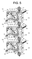
- Fig. 5 illustrates the third operation pattern.
- Solid-line arrows in Fig. 5 illustrate the power transmission path according to the third operation pattern.
- the power is transmitted from the sub motor 70 in each optional paper cassette 30 to the pickup roller 31 mounted in the same optional paper cassette 30 as the sub motor. Meanwhile, the power is transmitted to all of the feed rollers 32 from the main motor in the device main body 2.
- the gear 54 in each optional, paper cassette 30 is connected via the gears 59, 61, and 72 to the sub motor 70 mounted in the same optional paper cassette as the gear 54.
- the power is transmitted from the sub motor 70 in the third paper cassette 302 to the pickup roller 31 in the third paper cassette 302.
- the gear 62 is connected to the gear 51 via the gears 574, 573, 572, 571, 56, 552, 551, and 52.
- the gear 51 is connected to the gear 58 via the gears 52, 551, 552, and 56. Accordingly, when the optional paper cassettes 30 are vertically mounted below the device main body 2, the feed roller 32 mounted in each optional paper cassette 30 receives the power from the main motor in the device main body 2.
- the feed rollers 32 mounted in all of the optional paper cassettes 30 receive the power from the main motor mounted in the device main body 2.
- the sub motor 70 is driven to operate only the pickup roller 31 in the optional paper cassette 30 which is selected by the controller for paper feeding.
- the gears 53 and 60 are not attached to the bracket 100.
- each optional paper cassette 30 is not limited to the above-described preferred embodiment.
- the most appropriate operation pattern can be constructed according to a size of the optional paper cassette 30 and a layout of the pickup roller 31 and the feed roller 32 etc.
- two or more power transmission paths may be formed from one power source to either the pickup roller 31 or the feed roller 31.
- the studs may be arranged to enable a plurality of the gear range paths from the sub motor 70 to be formed on the bracket 100.
- the power transmission mechanism in both the paper feeding mechanism and the paper transporting mechanism of the optional paper cassette 30 is the gear range.
- other power transmission mechanism such as a belt transmission mechanism, can be used partially or entirely.
- the image forming device 1 can be used not only in a printer but also in a copy machine, a facsimile, and a multi function peripheral having both a copy function and a facsimile function.
- the image forming portion 3 can use not only an electrophotographic system but also other kinds of systems, such as an inkjet system.
Landscapes
- Physics & Mathematics (AREA)
- General Physics & Mathematics (AREA)
- Sheets, Magazines, And Separation Thereof (AREA)
Abstract
Description
- The present invention relates to an image forming device used in a copy machine, a facsimile, and a printer.
- In a conventional image forming device, optional paper cassettes are sequentially added from top to bottom below a device main body. Thus, a large number of papers can be stacked. Also, various sized recording papers and various types of recording papers can be stacked and selectively used.
- Power to feed and transport the recording paper from the optional paper cassette is transmitted from a motor mounted in the device main body to the optional paper cassette. However, the conventional image forming device has only one power transmission path. Accordingly, if a failure occurs in the motor or a component of the power transmission path, a paper feeding mechanism and a paper transporting mechanism of the optional paper cassette may stop operating partially or entirely. Also, in the case in which the device main body is mounted with a plurality of optional paper cassettes, one motor causes a lack of torque in some specifications. As a result, the paper feeding mechanism and the paper transporting mechanism of all of the optional paper cassettes may stop operating. In order to overcome the above-described problems, extra motors are added just to drive the paper feeding mechanism and the paper transporting mechanism of the optional paper cassettes. In such a case, however, an optional paper cassette with another power transmission path is needed to be replaced, resulting in an increase of manufacturing cost.
- In the conventional image forming device, one motor in the device main body drives all of the paper feeding mechanism and the paper transporting mechanism. Therefore, each time as the optional paper cassette is added, a load on the motor increases. Accordingly, assuming that a plurality of optional paper cassettes are added to the device main body, the device main body is pre-designed to be mounted with an expensive motor having a large power output. Otherwise, according to some specifications of the motor in the device main body, a lack of torque may occur when the motor drives the paper transporting mechanism of the optional paper cassette. When the recording paper is fed from a main cassette or an upper optional paper cassette, the motor simultaneously drives the paper transporting mechanism of lower optional paper cassettes, which do not need to operate. As a result, the power is consumed wastefully.
- Conventionally, when the recording paper is fed from the optional paper cassettes located below a second optional paper cassette from the top, a feed roller, which is mounted along the recording paper transportation path in the optional paper cassette, transports the recording paper towards the device main body. In such cases, all of the motors mounted in the paper cassettes located above the fourth optional paper cassette are also required to be driven. As a result, the power is consumed wastefully.
- In order to overcome the problems described above, according to preferred embodiments of the present invention, an image forming device can provide a plurality of operation patterns (a combination of a power source and a power transmission path) of both a paper feeding mechanism and a paper transporting mechanism of an optional paper cassette. Therefore, an appropriate operation pattern can be selected accordingly.
- According to a preferred embodiment of the present invention, the image forming device includes at least one optional paper cassette for paper feeding vertically mounted below a device main body having an image forming portion. A recording paper is transported from the optional paper cassette to the image forming portion through a recording paper transportation path in the optional paper cassette and a recording paper transportation path in the device main body. Each optional paper cassette has a recording paper storage portion, a pickup roller, and a feed roller. A pile of recording papers is stacked in the recording paper storage portion. The pickup roller picks up the recording paper from the recording paper storage portion towards the recording paper transportation path in the optional paper cassette. The feed roller transports the recording paper from upstream to downstream through the recording paper transportation path in the optional paper cassette. The combination of the power source and the power transmission path, which are used to drive the pickup roller and the feed roller, can be optionally changed. As a result, a plurality of operation patterns can be constructed.
- According to the above-described preferred embodiment of the present invention, if a failure occurs in the paper feeding mechanism and the paper transporting mechanism of the optional paper cassette, a user or a service person can change the operation pattern. As a result, the user can avoid a state in which the optional paper cassettes become partially or entirely inoperative. In addition, upon consideration of a component cost and a load on a motor in the device main body, an appropriate operation pattern can be selected accordingly.
- In particular, the image forming device of the present invention includes at least one optional paper cassette used for paper feeding vertically mounted below a device main body. A recording paper is transported from the optional paper cassette to an image forming portion through a recording paper transportation path in the optional paper cassette and a recording paper transportation path in the device main body.
- According to another preferred embodiment of the present invention, the power transmission path is constructed using only gears attached to a bracket, which is mounted in each optional paper cassette. The bracket is mounted with a plurality of gear attaching portions so that a path of gear range can be changed accordingly.
- According to such a preferred embodiment of the present invention, the power transmission path in the optional paper cassette can be optionally changed. In addition, since the power transmission path is constructed using only the gears, a power loss can be reduced.
- According to another preferred embodiment, in the image forming device of the present invention, the power source is either a main motor mounted in the device main body or a sub motor mounted in each optional paper cassette.
- According to such a preferred embodiment of the present invention, if a failure occurs in the paper feeding mechanism and the paper transporting mechanism of the optional paper cassette, the operation pattern of the pickup roller and the feed roller can be changed. As a result, the user can avoid a state in which the optional paper cassettes become inoperative. In addition, upon consideration of a component cost and a load on the motor in the device main body, an appropriate operation pattern can be selected accordingly.
- In order to overcome the above-described problems, according to preferred embodiments of the present invention, a load on a motor in a device main body can be reduced when an optional paper cassette is used. In addition, power is not consumed wastefully.
- According to a preferred embodiment of the present invention, an image forming device includes at least one optional paper cassette used for paper feeding vertically mounted below the device main body having an image forming portion. A recording paper is transported from the optional paper cassette to the image forming portion through recording paper transportation paths in both the optional paper cassette and the device main body. Each optional paper cassette has a recording paper storage portion, a pickup roller, a feed roller, and a motor. A pile of recording papers is stacked in the recording paper storage portion. The pickup roller picks up the recording paper from the recording paper storage portion towards the recording paper transportation path in the optional paper cassette. The feed roller transports the recording paper from upstream to downstream through the recording paper transportation path in the optional paper cassette. The pickup roller is rotated by power transmitted from the motor mounted in the same optional paper cassette as the pickup roller. The feed roller is rotated by power transmitted from the motor mounted in an optional paper cassette located below the optional paper cassette where such rotated feed roller is provided.
- According to the above-described preferred embodiment of the present invention, the image forming device is not required to include an expensive motor having a large power output in the device main body. Therefore, a manufacturing cost of the image forming device can be reduced. In addition, the optional paper cassettes can be added without considering the load on the motor in the device main body.
- According to another preferred embodiment of the present invention, each optional paper cassette has an output transmission mechanism and an input transmission mechanism. The output transmission mechanism is connected to the motor in the optional paper cassette. The input transmission mechanism is connected to the feed roller in the optional paper cassette. When the optional paper cassettes are vertically mounted below the device main body, the output transmission mechanism of a lower optional paper cassette is connected to the input transmission mechanism of an upper optional paper cassette.
- According to such a preferred embodiment of the present invention, the image forming device is not required to include an expensive motor having a large power output in the device main body. Therefore, the manufacturing cost of the image forming device can be reduced. In addition, the optional paper cassettes can be added without considering the load on the motor in the device main body.
- According to another preferred embodiment of the present invention, both the input transmission mechanism and the output transmission mechanism are constructed using only gears.
- According to the above-described preferred embodiment of the present invention, a power transmission path in the optional paper cassette can be optionally constructed. In addition, by constructing the power transmission path using only the gears, a power loss in the power transmission path can be reduced.
- In order to overcome the above-described problems, a motor in an optional paper cassette of the present invention does not consume power wastefully.
- According to a preferred embodiment of the present invention, an image forming device includes at least one optional paper cassette used for paper feeding vertically mounted below a device main body having an image forming portion. A recording paper is transported from the optional paper cassette to the image forming portion through recording paper transportation paths in both the optional paper cassette and the device main body. Each optional paper cassette has a recording paper storage portion, a pickup roller, a feed roller, and the motor. A pile of recording papers is stacked in the recording paper storage portion. The pickup roller picks up the recording paper from the recording paper storage portion towards the recording paper transportation path in the optional paper cassette. The feed roller transports the recording paper from upstream to downstream through the recording paper transportation path in the optional paper cassette. The pickup roller receives the power transmitted from the motor mounted in the same optional paper cassette as the pickup roller. The feed roller receives the power transmitted from a motor mounted in the device main body.
- According to the above-described preferred embodiment of the present invention, the recording paper can be picked up and transported only by driving the motor mounted in the device main body and the motor mounted in the optional paper cassette selected for paper feeding. In other words, there is no need to drive other motors mounted in the unselected optional paper cassettes. As a result, the power is not consumed wastefully, and a noise can be reduced.
- According to another preferred embodiment of the present invention, the power transmission path to both the feed roller and the pickup roller can be constructed using only gears.
- According to such a preferred embodiment of the present invention, a power loss in the power transmission path is small. In addition, the power transmission path can be optionally changed.
- Embodiments of the present invention will become more apparent from the following detailed description with reference to the attached drawings.
- Fig. 1 is a cross section view from a backside of an image forming device according to a preferred embodiment of the present invention.
- Figs. 2A and 2B illustrate a bracket mounted in an optional paper cassette. Fig. 2A illustrates a bracket having no gears attached. Fig. 2B illustrates a bracket having all of the gears attached.
- Fig. 3 illustrates a first operation pattern.
- Fig. 4 illustrates a second operation pattern.
- Fig. 5 illustrates a third operation pattern.
- A description will be made of an image forming device according to a preferred embodiment of the present invention. In the preferred embodiment of the present invention, a printer using an electrophotographic system is described as an example of the image forming device.
- As illustrated in Fig. 1, an
image forming device 1 includes a device main body 2. The device main body 2 includes animage forming portion 3 and amain cassette 20. Recording papers are stacked in themain cassette 20. At least one optional paper cassette 30 can be vertically mounted below the device main body 2. The recording papers are also stacked in the optional paper cassette 30. The recording paper is transported to acopy receiving tray 7 through a recordingpaper transportation path 35 in each optional paper cassette 30 and recordingpaper transportation paths - The
main cassette 20 is mounted at a bottom of the device main body 2. Themain cassette 20 includes a recordingpaper storage portion 27. The recording papers are stacked in the recordingpaper storage portion 27. The recordingpaper storage portion 27 is horizontally inserted from a front side of the device main body 2 into anattachment portion 29 mounted in the device main body 2. - The recording
paper transportation path 4 is provided in the device main body 2. The recordingpaper transportation path 4 leads from themain cassette 20 through theimage forming portion 3 to thecopy receiving tray 7. Thecopy receiving tray 7 is mounted on an upper part of the device main body 2. Along the recordingpaper transportation path 4, apickup roller 21, resistrollers 22, theimage forming portion 3, and a fixing device are sequentially arranged in a paper transportation direction. The fixing device includes aheat roller 11 and apress roller 17. A controller mounted in the device main body 2 controls the above-described devices, which are driven by power transmitted from a main motor (not illustrated in Fig. 1) provided in the device main body 2. - A
bottom plate 28 is provided at a bottom of the recordingpaper storage portion 27 in themain cassette 20. A pile ofrecording papers 90 can be stacked on thebottom plate 28. When the recordingpaper storage portion 27 is inserted into theattachment portion 29, a paper feeding side of thebottom plate 28 elevates by being urged upward by an urging spring (not illustrated in Fig. 1). As a result, an edge of an uppermost recording paper of the pile ofrecording papers 90 is pressed against thepickup roller 21. - A clutch is attached to a shaft of the
pickup roller 21. The clutch transmits or cuts off the power transmitted from the main motor to the shaft. When the clutch is connected in response to a request for paper feeding from the controller, one sheet of recording paper is picked up from the pile ofrecording papers 90. The picked-up recording paper is transported towards theimage forming portion 3. - A toner image is transferred onto the recording paper at the
image forming portion 3. In the following, a description will be made of a transferring process of the toner image. A surface of aphotoconductive drum 16 is charged by acharger 15. Alaser scanning device 14 exposes the surface of the chargedphotoconductive drum 16. As a result, an electrostatic latent image is formed on thephotoconductive drum 16. The toner is attracted to the electrostatic latent image from a developingroller 13. Accordingly, the toner image is retained on the surface of thephotoconductive drum 16. The toner image is transferred onto the recording paper by atransfer roller 12. A residual toner remaining on the surface of thephotoconductive drum 16 is scraped off by aroller 18. The recording paper with the transferred toner image passes through the fixing device, whereby the toner image is fixed onto the recording paper. The recording paper is then output onto thecopy receiving tray 7. - Next, a description will be made of the optional paper cassette 30, and a paper feeding mechanism and a paper transporting mechanism of the optional paper cassette 30. As illustrated in Fig. 1, according to preferred embodiments of the present invention, three
optional paper cassettes image forming device 1 has four paper cassettes including themain cassette 20 in the device main body 2. Themain cassette 20, a topoptional paper cassette 301, a nextoptional paper cassette 302, and a bottomoptional paper cassette 303 hereafter will be respectively referred to as a first paper cassette, asecond paper cassette 301, athird paper cassette 302, and afourth paper cassette 303. - The optional paper cassette 30 includes a box-shaped
housing 39 and astorage portion 38. Thestorage portion 38 is pulled in and out at a front side of thehousing 39, and accommodates the pile ofrecording papers 90. A vertically extendingtransportation path 35 is also mounted in the optional paper cassette 30. - Each optional paper cassette 30 includes a
pickup roller 31 and afeed roller 32, and also includes asub motor 70 if needed. Thepickup roller 31 picks up one sheet of recording paper at a time from thestorage portion 38, and transports the recording paper towards thetransportation path 35. Thefeed roller 32 transports the recording paper from upstream to downstream through thetransportation path 35. Atransportation path 34 connects thestorage portion 38 and thetransportation path 35. The recording paper picked up by thepickup roller 31 passes through thetransportation paths feed roller 32 in thetransportation path 35 is arranged upstream of a junction of thefeed roller 32 and thetransportation path 34. Thefeed roller 32 transports the recording paper, which has been transported from the optional paper cassette 30 located directly below, further to downstream. - A
transportation path 5 is provided in the device main body 2. Thetransportation path 5 connects thetransportation path 35 in thesecond paper cassette 301 to thetransportation path 4 in the device main body 2 in order to transport the recording paper. Afeed roller 26 is mounted on a lower position of thetransportation path 5. Thefeed roller 26 feeds the recording paper transported from thesecond paper cassette 301 to thetransportation path 5. Thefeed roller 26 is rotated by the power transmitted from the main motor in the device main body 2. In the following, a description will be made of an example in which the recording paper is fed from thefourth paper cassette 303. The recording paper picked up by thepickup roller 31 in thefourth paper cassette 303 is transported to downstream by thefeed roller 32 in thethird paper cassette 302 and thefeed roller 32 in thesecond paper cassette 301. The recording paper then enters thetransportation path 5 in the device main body 2, and is transported by thefeed roller 26 to thetransportation path 4. - Next, a description will be made of an operation pattern of the
rollers pickup roller 31 and thefeed roller 32 in each optional paper cassette 30. According to preferred embodiments of the present invention, three operation patterns can be constructed. The main motor in the device main body 2 or thesub motor 70 in each optional paper cassette 30 is optionally selected as the power source. According to a first operation pattern, the main motor in the device main body 2 rotates therollers rollers motor 70 in each optional paper cassette 30 rotates both thepickup roller 31 and thefeed roller 32 mounted in the same optional paper cassette 30 as the sub motor. According to a third operation pattern, thepickup roller 31 is rotated by the power transmitted from thesub motor 70 mounted in the same optional paper cassette 30 as the pickup roller. Thefeed roller 32 is rotated by the power transmitted from the main motor in the device main body 2. - In the
image forming device 1 according to preferred embodiments of the present invention, the operation patterns in the, optional paper cassette 30 can be changed just by replacing gears on abracket 100. Only gears can be attached to thebracket 100. Therefore, when the gears are attached to thebracket 100 according to the first operation pattern, if a failure occurs in a portion of the gears, the optional paper cassette 30 can be used again by replacing the gears according to the second operation pattern, which does not use the main motor. When the gears are attached to thebracket 100 according to the second or third operation pattern, if a failure occurs in thesub motor 70, the optional paper cassette 30 can be used again by replacing the gears according to the first operation pattern in which the power is transmitted only from the main motor. If another optional paper cassette 30 is added when the gears are attached according to the first operation pattern, an excess load is placed on the main motor in the device main body 2, resulting in a lack of torque. In such a case, if a user or a service person replaces the gears according to the second operation pattern, the optional paper cassette can be added without increasing the load on the main motor. According to the second operation pattern, as more optional paper cassettes 30 are added, both a noise from thesub motor 70 and a power consumption increase. In such a case, if the user or the service person replaces the gears according to the third operation pattern, the main motor and only onesub motor 70 are used simultaneously. Thus, the noise from theimage forming device 1 can be reduced as a whole. As a result, the power consumption in theimage forming device 1 can be reduced. - As illustrated in Fig. 2A, the
bracket 100 is provided on a backside of the optional paper cassette 30. Agear 54, which is used to drive thepickup roller 31, and agear 62, which is used to drive thefeed roller 32, are attached to thebracket 100. Thegear 54 is fixed at an edge of arotation shaft 311 of the pickup roller 31 (see Fig. 1). Thegear 62 is fixed at an edge of arotation shaft 321 of the feed roller 32 (see Fig. 1). - A plurality of studs (gear attaching shafts) are attached to the
bracket 100. An idle gear, which is driven to transmit the power to thegears image forming device 1, a combination of the gears attached to thebracket 100 can be changed. Therefore, three operation patterns (patterns of gear range) can be constructed. Fig. 2B illustrates the gears attached to all of the studs. Only the necessary gears according to the required operation pattern are attached to thebracket 100, and thus the operation pattern is constructed. Preferably, two or more gear ranges according to two or more operation patterns are not constructed at the same time. In other words, each gear diameter is defined so that some of the gears interact with the gears arranged according to another gear range. - Fig. 3 illustrates the first operation pattern. Solid-line arrows in Fig. 3 illustrate the power transmission path according to the first operation pattern. According to the first operation pattern, the main motor in the device main body 2 rotates the
pickup rollers 31 and thefeed rollers 32 in all of the optional paper cassettes 30. A power transmission mechanism driven by the main motor is constructed in the device main body 2 in order to transmit the power from the main motor to the optional paper cassette 30. Anoutput gear 19 is attached to an end edge of the power transmission mechanism. - A
first linking gear 51 is attached to an upper edge of eachbracket 100. Asecond linking gear 58 is attached to a lower edge of eachbracket 100. When two optional paper cassettes 30 are vertically mounted, thesecond linking gear 58 in the upper optional paper cassette 30 engages with thefirst linking gear 51 in the lower optional paper cassette 30. Thefirst linking gear 51 in thesecond paper cassette 301 engages with theoutput gear 19 in the device main body 2. - The
first linking gear 51 is supported by anarm 101. Thearm 101 can be swung around a shaft of anidle gear 52. Thearm 101 and thehousing 39 are connected by aspring 102. Thespring 102 urges thefirst linking gear 51 towards thesecond linking gear 58 in the upper optional paper cassette or theoutput gear 19 in the device main body. Therefore, thefirst linking gear 51 reliably engages with thesecond linking gear 58, and thefirst linking gear 51 reliably engages with theoutput gear 19. As a result, the power from the main motor can be appropriately transmitted to the optional paper cassette 30. - The
gear 54 is driven to transmit the power to thepickup roller 31. Thegear 54 is connected via anidle gear 53 and theidle gear 52 to thefirst linking gear 51 mounted in the same optional paper cassette 30 as thegear 54 so that the power can be transmitted. Thegear 62 is driven to transmit the power to thefeed roller 32. Thegear 62 is connected viaidle gears first linking gear 51 mounted in the same optional paper cassette 30 as thegear 62 so that the power can be transmitted. Thefirst linking gear 51 is connected via the idle gears 52, 551,552, and 56 to thesecond linking gear 58 mounted in the same optional paper cassette 30 as thefirst linking gear 51 so that the power can be transmitted. Accordingly, when the optional paper cassettes 30 are vertically mounted below the device main body 2, the power is transmitted from the main motor in the device main body 2 to all of thepickup rollers 31 and thefeed rollers 32 mounted in all of the optional paper cassettes 30, and consequently, all of therollers - According to the first operation pattern, since the
sub motor 70 is not driven, thesub motor 70 is not required to be attached to thebracket 100. Sinceidle gears sub motor 70, are not driven, the idle gears 59, 60, and 61 are not required to be attached to thebracket 100. - With reference to Figs. 1 and 3, a description will be made of an example of an operation for transporting the recording paper from the
fourth paper cassette 303 according to the first operation pattern. Abottom plate 37 is mounted at a bottom of thestorage portion 38 in thefourth paper cassette 303. A pile ofrecording papers 90 is stacked on thebottom plate 37. A paper feeding side of thebottom plate 37 is elevated by being urged upward by an urging spring (not illustrated in Figs. 1 and 3). As a result, an edge of an uppermost recording paper of the pile ofrecording papers 90 is pressed against thepickup roller 31. - A clutch 541 is attached to the
gear 54. In response to a connection request from the controller, only the clutch 541 in thefourth paper cassette 303 selected for paper feeding is connected, whileother clutches 541 in theunselected paper cassettes main cassette 20 are not connected. Accordingly, only therotation shaft 311 in thefourth paper cassette 303 is connected to thegear 54 and rotated. As a result, the recording paper is transported by thepickup roller 31 from thestorage portion 38 into thetransportation path 34. - The recording paper is transported from the
transportation path 34 to downstream through thetransportation paths 35 in both the third andsecond paper cassettes feed rollers 32 in both the third andsecond paper cassettes transportation path 5 in the device main body 2 from thetransportation path 35 in thesecond paper cassette 301. The recording paper is then transported further downstream through thetransportation path 5 by thefeed roller 26 in the device main body 2, and transported, into theimage forming portion 3 through thetransportation path 4. - Fig. 4 illustrates the second operation pattern. Solid-line arrows in Fig. 4 illustrate the power transmission path according to the second operation pattern. According to the second operation pattern, the
sub motor 70 is mounted in each optional paper cassette 30. The power from thesub motor 70 is transmitted to thepickup roller 31 mounted in the same optional paper cassette 30 as thesub motor 70. The power from thesub motor 70 is also transmitted to thefeed roller 32 mounted in the optional paper cassette 30 located directly above. Therefore, the power from the main motor in the device main body 2 is not transmitted to thepickup roller 31 and thefeed roller 32 in the optional paper cassette 30. - The
sub motor 70 is fixed on a surface of thebracket 100 on an opposite side of a gear attaching side. Anoutput shaft 71 of thesub motor 70 penetrates in a thickness direction through thebracket 100 and protrudes on the gear attaching side. Anoutput gear 72 is fixed on an edge of theoutput shaft 71. - The
gear 54 in each optional paper cassette 30 is connected via the idle gears 59 and 61 to theoutput gear 72. As a result, the power from thesub motor 70 in each optional paper cassette 30 is transmitted only to thepickup roller 31 mounted in the same optional paper cassette 30 as the sub motor. In other words, for example, the power from thesub motor 70 in thethird paper cassette 302 is transmitted only to thepickup roller 31 in thethird paper cassette 302. - When two optional paper cassettes 30 are vertically mounted, the
gear 62 in the upper optional paper cassette 30 is connected to thegear 72 fixed on the output shaft of thesub motor 70 in the lower optional paper cassette 30 via thegears gears feed roller 32 in the upper optional paper cassette 30 receives the power transmitted only from thesub motor 70 in the lower optional paper cassette 30. - According to the second operation pattern, the
gears sub motor 70 to the upper optional paper cassette 30. Thegears feed roller 32. By connecting the output transmission mechanism of the lower optional paper cassette 30 to the input transmission mechanism in the upper optional paper cassette 30, the power from thesub motor 70 in the lower optional paper cassette 30 is transmitted to thefeed roller 32 in the upper optional paper cassette 30 and rotates thefeed roller 32. According to the second operation pattern, the gear 551 (see Fig. 2B) is not used. Therefore, the output transmission mechanism and the input transmission mechanism in one optional paper cassette 30 do not transmit the power to each other. Further, by preventing thegear 552 from being used, or by preventing both thegears
[0059] According to the second operation pattern, it is not necessary to transmit the power between the device main body 2 and thesecond paper cassette 301. Therefore, theidle gear 60 is not mounted in thesecond paper cassette 301. Thus, the power from thesub motor 70 in thesecond paper cassette 301 is not transmitted to the device main body 2. - With reference to Figs. 1 and 4, a description will be made of an example of an operation for transporting the recording paper from the
fourth paper cassette 303 according to the second operation pattern, In response to a request for paper feeding from the controller in the device main body 2, thesub motors 70 in the third andfourth paper cassettes fourth paper cassette 303 is connected, the recording paper is transported through thetransportation path 34 to thetransportation path 35. The recording paper is then transported towards the device main body 2 by thefeed rollers 32 in both the third andsecond paper cassettes feed roller 32 in thethird paper cassette 302 is rotated by the power transmitted from thesub motor 70 in thefourth paper cassette 303. Thefeed roller 32 in thesecond paper cassette 301 is rotated by the power transmitted from thesub motor 70 in thethird paper cassette 302. - In the above-described example in which the recording paper is fed from the third or
fourth paper cassettes sub motor 70 in thesecond paper cassette 301 is not required to be driven. Therefore, according to the second operation pattern, only thesub motors 70 in thethird paper cassette 302 and thefourth paper cassette 303 selected for paper feeding are required to be driven. When the recording paper is fed from thesecond paper cassette 301 located directly below the device main body 2, only thepickup roller 31 in thesecond paper cassette 301 is required to be rotated. Therefore, since thefeed rollers 32 in the second, third, andfourth paper cassettes sub motor 70 in thesecond paper cassette 301 is driven. - Fig. 5 illustrates the third operation pattern. Solid-line arrows in Fig. 5 illustrate the power transmission path according to the third operation pattern. According to the third operation pattern, the power is transmitted from the
sub motor 70 in each optional paper cassette 30 to thepickup roller 31 mounted in the same optional paper cassette 30 as the sub motor. Meanwhile, the power is transmitted to all of thefeed rollers 32 from the main motor in the device main body 2. - In the same manner as the second operation pattern, the
gear 54 in each optional, paper cassette 30 is connected via thegears sub motor 70 mounted in the same optional paper cassette as thegear 54. For example, the power is transmitted from thesub motor 70 in thethird paper cassette 302 to thepickup roller 31 in thethird paper cassette 302. - In the same manner as the first operation pattern, the
gear 62 is connected to thegear 51 via thegears gear 51 is connected to thegear 58 via thegears feed roller 32 mounted in each optional paper cassette 30 receives the power from the main motor in the device main body 2. - In other words, according to the third operation pattern, the
feed rollers 32 mounted in all of the optional paper cassettes 30 receive the power from the main motor mounted in the device main body 2. Thesub motor 70 is driven to operate only thepickup roller 31 in the optional paper cassette 30 which is selected by the controller for paper feeding. Additionally, according to the third operation pattern, thegears bracket 100. - A description has been made of the image forming device according to a preferred embodiment of the present invention. However, the operation patterns of each optional paper cassette 30 are not limited to the above-described preferred embodiment. The most appropriate operation pattern (gear range) can be constructed according to a size of the optional paper cassette 30 and a layout of the
pickup roller 31 and thefeed roller 32 etc. - As for the paper feeding mechanism and the paper transporting mechanism of the optional paper cassette 30, two or more power transmission paths may be formed from one power source to either the
pickup roller 31 or thefeed roller 31. For example, the studs may be arranged to enable a plurality of the gear range paths from thesub motor 70 to be formed on thebracket 100. - In the above-described preferred embodiment, the power transmission mechanism in both the paper feeding mechanism and the paper transporting mechanism of the optional paper cassette 30 is the gear range. However, other power transmission mechanism, such as a belt transmission mechanism, can be used partially or entirely.
- The
image forming device 1 according to the preferred embodiment of the present invention can be used not only in a printer but also in a copy machine, a facsimile, and a multi function peripheral having both a copy function and a facsimile function. Theimage forming portion 3 can use not only an electrophotographic system but also other kinds of systems, such as an inkjet system. - While the present invention has been described with respect to preferred embodiments thereof, it will be apparent to those skilled in the art that the disclosed invention may be modified in numerous ways and may assume many embodiments other than those specifically set out and described above. Accordingly, the appended claims are intended to cover all modifications of the present invention that fall within the true spirit and scope of the present invention.
Claims (8)
- An image forming device (1) comprising:a device main body (2) which includes an image forming portion (3) and recording paper transportation paths (5, 4); andat least one optional paper cassette (301, 302, 303) which can be vertically mounted below the device main body (2),wherein each optional paper cassette (301, 302, 303) includes a recording paper transportation path (35), a recording paper storage portion (38), a pickup roller (31) and a feed roller (32); andthe recording paper storage portion (38) accommodates a pile of recording papers (90), the pickup roller (31) picks up the recording paper from the recording paper storage portion (38) towards the recording paper transportation path (35) in the optional paper cassette, and the feed roller (32) transports the recording paper through the recording paper transportation path (35) in the optional paper cassettes (301, 302, 302) from upstream to downstream, andcharacterized in that a combination of a power source and a power transmission path, which are used to drive both the pickup roller (31) and the feed roller (32), can be optionally changed.
- The image forming device according to claim 1, characterized in that each optional paper cassette (301, 302, 303) includes a bracket (100) having a plurality of gear attaching portions, and a power transmission path in each optional paper cassette (301, 302, 303) is constructed using only gears attached to the bracket (100).
- The image forming device according to claims 1 and 2, characterized in that a power source is either a main motor mounted in the device main body (2) or a sub motor (70) mounted in the optional paper cassettes (301, 302, 303).
- An image forming device comprising:a device main body (2) which includes an image forming portion (3) and a recording paper transportation path (5, 4); andat least one optional paper cassette (301, 302, 303) which can be vertically mounted below the device main body (2),wherein each optional paper cassette (301, 302, 303) includes a recording paper transportation path (35), a recording paper storage portion (38), a motor (70), a pickup roller (31), and a feed roller (32); andthe recording paper storage portion (38) accommodates a pile of recording papers (90), the pickup roller (31) picks up the recording paper from the recording paper storage portion (38) towards the recording paper transportation path (35) in the optional paper cassette, and the feed roller (32) transports the recording paper through the recording paper transportation path (35) in the optional paper cassettes (301, 302, 303) from upstream to downstream, andcharacterized in that the pickup roller (31) is rotated by power transmitted from the motor (70) mounted in the same optional paper cassette (301, 302, 303) as the pickup roller, and the feed roller (32) is rotated by power transmitted from the motor (70) mounted in a lower optional paper cassette (301, 302, 303).
- The image forming device according to claim 4, characterized in that each optional paper cassette (301, 302, 303) includes an output transmission mechanism and an input transmission mechanism, the output transmission mechanism is connected to the motor (70) mounted in the optional paper cassette (301, 302, 303), the input transmission mechanism is connected to the feed roller (32), and when the optional paper cassettes (301, 302, 303) are vertically mounted, the output transmission mechanism in a lower optional paper cassette (301, 302, 303) is connected to the input transmission mechanism in an upper optional paper cassette (301, 302, 303).
- The image forming device according to claim 5, characterized in that both the input transmission mechanism and the output transmission mechanism are constructed using only gears.
- The image forming device comprising:a device main body (2) which includes a main motor, an image forming portion (3), and recording paper transportation paths (5, 4); andat least one optional paper cassette (301, 302, 303) which can be vertically mounted below the device main body (2),wherein each optional paper cassette (301, 302, 303) includes a recording paper transportation path (35), a recording paper storage portion (38), a sub motor (70), a pickup roller (31), and a feed roller (32); andthe recording paper storage portion (38) accommodates a pile of recording papers (90), the pickup roller picks up the recording paper from the recording paper storage portion (38) towards the recording paper transportation path (35) in the optional paper cassette (301, 302, 303), and the feed roller (32) transports the recording paper through the recording paper transportation path (35) in the optional paper cassette (301, 302, 303) from upstream to downstream, andcharacterized in that the pickup roller (31) is rotated by power transmitted from the sub motor (70) mounted in the same optional paper cassette (301, 302, 303) as the pickup roller, and the feed roller is rotated by power transmitted from the main motor mounted in the device main body (2).
- The image forming device according to claim 7, characterized in that power transmission paths to both the pickup roller (31) and the feed roller (32) are constructed using only gears.
Applications Claiming Priority (6)
| Application Number | Priority Date | Filing Date | Title |
|---|---|---|---|
| JP2006028619 | 2006-02-06 | ||
| JP2006028620 | 2006-02-06 | ||
| JP2006028621 | 2006-02-06 | ||
| JP2006281502A JP2007230776A (en) | 2006-02-06 | 2006-10-16 | Image forming device |
| JP2006281501A JP2007230775A (en) | 2006-02-06 | 2006-10-16 | Image forming device |
| JP2006281500A JP4807215B2 (en) | 2006-02-06 | 2006-10-16 | Image forming apparatus |
Publications (2)
| Publication Number | Publication Date |
|---|---|
| EP1816524A2 true EP1816524A2 (en) | 2007-08-08 |
| EP1816524A3 EP1816524A3 (en) | 2010-11-03 |
Family
ID=38042750
Family Applications (1)
| Application Number | Title | Priority Date | Filing Date |
|---|---|---|---|
| EP06022424A Withdrawn EP1816524A3 (en) | 2006-02-06 | 2006-10-26 | Image forming device with optional paper cassette |
Country Status (3)
| Country | Link |
|---|---|
| US (1) | US20070183827A1 (en) |
| EP (1) | EP1816524A3 (en) |
| CN (1) | CN101016125B (en) |
Families Citing this family (3)
| Publication number | Priority date | Publication date | Assignee | Title |
|---|---|---|---|---|
| JP5828370B2 (en) * | 2011-02-28 | 2015-12-02 | 株式会社リコー | Paper feeding device and image forming apparatus |
| JP6318648B2 (en) * | 2014-01-27 | 2018-05-09 | 株式会社リコー | Image forming apparatus and image forming method |
| CN112645090B (en) * | 2019-10-09 | 2025-02-11 | 京瓷办公信息系统株式会社 | Document feeding device |
Family Cites Families (9)
| Publication number | Priority date | Publication date | Assignee | Title |
|---|---|---|---|---|
| JPS6181334A (en) * | 1984-09-27 | 1986-04-24 | Toshiba Corp | Paper feeder |
| JPH02276736A (en) * | 1989-04-13 | 1990-11-13 | Konica Corp | Paper feeding device of recorder |
| JPH03284554A (en) * | 1990-03-30 | 1991-12-16 | Canon Inc | Paper feeder |
| JPH04169432A (en) * | 1990-10-31 | 1992-06-17 | Brother Ind Ltd | Paper feeding device |
| JP2836268B2 (en) * | 1991-02-12 | 1998-12-14 | 富士ゼロックス株式会社 | Paper feeder of image forming device |
| JP3226587B2 (en) * | 1992-01-28 | 2001-11-05 | 株式会社リコー | Multi-stage paper feeder |
| JPH08208058A (en) * | 1994-10-20 | 1996-08-13 | Minolta Co Ltd | Paper feeding device |
| JP3710401B2 (en) * | 2001-08-06 | 2005-10-26 | キヤノン株式会社 | Image forming apparatus |
| US7761046B2 (en) * | 2003-10-02 | 2010-07-20 | Sharp Kabushiki Kaisha | Hybrid paper supply module and image forming apparatus equipped with such hybrid paper supply module, and also paper supply mechanism and image forming apparatus equipped with such paper supply mechanism |
-
2006
- 2006-10-26 EP EP06022424A patent/EP1816524A3/en not_active Withdrawn
- 2006-11-17 US US11/560,918 patent/US20070183827A1/en not_active Abandoned
-
2007
- 2007-02-06 CN CN2007100067726A patent/CN101016125B/en not_active Expired - Fee Related
Non-Patent Citations (1)
| Title |
|---|
| None |
Also Published As
| Publication number | Publication date |
|---|---|
| CN101016125A (en) | 2007-08-15 |
| CN101016125B (en) | 2012-06-13 |
| EP1816524A3 (en) | 2010-11-03 |
| US20070183827A1 (en) | 2007-08-09 |
Similar Documents
| Publication | Publication Date | Title |
|---|---|---|
| CN200940049Y (en) | Paper Feeder and Imaging Equipment | |
| JP5979922B2 (en) | Sheet feeding apparatus and image forming apparatus | |
| US7410161B2 (en) | Sheet feeding apparatus, and image forming apparatus and image reading apparatus respectively equipped with sheet feeding apparatus | |
| JP5753827B2 (en) | Sheet conveying device, and image reading apparatus and image forming apparatus provided with the same | |
| JP2008304776A (en) | Drive joint mechanism of image forming apparatus | |
| US20030025263A1 (en) | Image forming apparatus | |
| CN100385343C (en) | Electrophotographic image forming apparatus and method of performing printing operation using a plurality of developing sections | |
| JP2019127390A (en) | Sheet transport device and image formation device | |
| US8254824B2 (en) | Recording medium conveying device and image forming apparatus | |
| US6837489B2 (en) | Jam removing apparatus of machine having ADF function | |
| US20030170048A1 (en) | Drive mechanism for electrophotographic image forming apparatus | |
| US6543758B2 (en) | Image forming apparatus | |
| US20070183827A1 (en) | Image forming device | |
| US7789386B2 (en) | Sheet transporting apparatus | |
| KR101379781B1 (en) | Drive mechanism and image forming device | |
| JP4807215B2 (en) | Image forming apparatus | |
| JP2001253562A (en) | Sheet feeding device and image forming device | |
| JP2004252007A (en) | Image forming device | |
| JP3786165B2 (en) | Sheet conveying apparatus and image forming apparatus | |
| JP2007230776A (en) | Image forming device | |
| JP4407653B2 (en) | Drive transmission mechanism and paper transport device having the same | |
| JP2008265914A (en) | Paper feeder and image forming device provided with this | |
| JP3991005B2 (en) | Driving force transmission mechanism in image forming apparatus | |
| JP2018131286A (en) | Paper feeding device and image forming apparatus having the same | |
| JP2004117990A (en) | Image forming device |
Legal Events
| Date | Code | Title | Description |
|---|---|---|---|
| PUAI | Public reference made under article 153(3) epc to a published international application that has entered the european phase |
Free format text: ORIGINAL CODE: 0009012 |
|
| AK | Designated contracting states |
Kind code of ref document: A2 Designated state(s): AT BE BG CH CY CZ DE DK EE ES FI FR GB GR HU IE IS IT LI LT LU LV MC NL PL PT RO SE SI SK TR |
|
| AX | Request for extension of the european patent |
Extension state: AL BA HR MK YU |
|
| PUAL | Search report despatched |
Free format text: ORIGINAL CODE: 0009013 |
|
| AK | Designated contracting states |
Kind code of ref document: A3 Designated state(s): AT BE BG CH CY CZ DE DK EE ES FI FR GB GR HU IE IS IT LI LT LU LV MC NL PL PT RO SE SI SK TR |
|
| AX | Request for extension of the european patent |
Extension state: AL BA HR MK RS |
|
| 17P | Request for examination filed |
Effective date: 20101228 |
|
| AKX | Designation fees paid |
Designated state(s): DE GB |
|
| 17Q | First examination report despatched |
Effective date: 20120720 |
|
| STAA | Information on the status of an ep patent application or granted ep patent |
Free format text: STATUS: THE APPLICATION HAS BEEN WITHDRAWN |
|
| 18W | Application withdrawn |
Effective date: 20120914 |